Note: Descriptions are shown in the official language in which they were submitted.
P12139CA00
¨1¨
PANEL DEVICE
The present invention relates to a panel device, particularly a roof light,
for a
recreational vehicle, comprising an at least substantially polygonal frame
which
surrounds an opening and comprising a window, which window is connected to the
frame for pivoting about a pivot axis and comprises a panel which extends over
the
opening, wherein provided between the frame and the window is at least a stay
device
which is manipulable between a first position, in which the window is forced
into a flat
state and closes the opening, and at least one second position in which the
window is
raised by the stay device and leaves the opening at least partially clear,
which stay
device comprises a stay which extends movably from an elongate guide at a
first outer
end and is connected pivotally to the window at an opposite, second outer end,
wherein the stay is adjustable in the guide between a first position, in which
the stay
lies at least substantially flat relative to the guide, and a second position
in which the
stay has taken on a raised state from the guide. The invention relates here
particularly
to a panel device, such as a skylight, in a caravan or camper van.
Such a skylight is for instance known from German patent application 10 2019
200 066.
The panel device described therein comprises a set of stays on either side of
the frame.
Lying over the frame is a transparent roof light which on a longitudinal side
is
connected pivotally to the frame and transversely thereof is coupled to the
stays
whereby the window can be opened. For this purpose one of the two stays
comprises
at its first outer end a handle whereby the stay can be manipulated between
the first
and second position. The relevant stay is connected by means of a flexible
cable to the
other stay so that the other stay will co-displace synchronously.
A drawback of this known configuration is an ingenious system of pulleys which
is
needed to guide the cable from the one to the other stay. This system not only
makes
the whole more susceptible to malfunction, but also requires additional
components
and the assembly time associated therewith. This is one of the reasons that
the known
Date Regue/Date Received 2023-04-13
P12139CA00
¨2¨
panel device is expensive. The direct operation of the relevant stay is also
relatively
heavy in that the other stay is also co-displaced therewith. In order to avoid
breaking,
the handle must take a relatively heavy and large form, which mars the
appearance of
the window.
The present invention has for its object, among others, to provide a panel
device, such
as a skylight for a recreational vehicle, which obviates one or more of these
drawbacks
to at least significant extent.
in order to achieve the stated object a panel device of the type described in
the
preamble has the feature according to the invention that the stay is coupled
to an
actuator via a flexible transmission, that the transmission comprises at least
one
tension-resistant pull member which is coupled to the stay and moves the stay
from
one of the first and second position to another of the first and second
position when
the actuator is energized, and that the at least one pull member is introduced
axially
movably into an axially at least substantially rigid yet flexible sleeve, a
first outer end
of which is fixed to or close to the stay and a second outer end of which is
attached to
or close to the actuator. The axially rigid yet flexible sleeve thus provides
for a guiding
of the pull member. This sleeve with pull member can be accommodated in a wall
of
the frame in relatively simple manner without this involving a significant
amount of
assembly time. The actuator coupled to the pull member simplifies and
facilitates
operation of the panel, if desired. The actuator can here be provided at a
practical
location in or at the window.
A particular embodiment of the panel device has the feature here according to
the
invention that the guide extends between the first position and the second
position on
a first side of the frame, transversely of the pivot axis, that the actuator
is provided on
a further side of the frame lying opposite the pivot axis, and that the at
least one
sleeve and pull member extend over at least a part of the first side and at
least a part
of the further side of the frame.
Date Regue/Date Received 2023-04-13
P12139CA00
-3-
In a particular embodiment the panel device has the feature according to the
invention
that the at least one pull member, particularly a first pull member, engages
on the stay
in a direction directed toward the first position, and that the at least one
pull member,
particularly a second pull member, engages on the stay in a direction directed
towards
the second position. The at least one pull member is here always coupled to
the stay
for tension, so that the first outer end thereof will always be pulled from
the one to
the other position. The transmission thus need not exert any pressure on the
stay, and
is conversely only placed under strain of tension.
A preferred embodiment of the panel device has the feature according to the
invention that the stay device comprises on an opposite side of the frame a
second
stay, that the at least one pull member, particularly the first pull member,
engages on
the second stay in a direction directed toward the second position, and that
the at
least one pull member, particularly the second pull member, engages on the
second
stay in a direction directed toward the first position. The panel is thus
coupled to a stay
on both sides, and the transmission provides for a mutual synchronization of
the
displacements performed by the two stays in their guide. A tension on the one
stay is
here also transmitted to the other stay, so that both will move synchronously
in the
same direction and over the same distance. A practical embodiment of the panel
device has the feature here according to the invention that the transmission
comprises
at least a pull member from a group of a substantially non-stretch cable,
cord, chain
and belt.
With a view to simple assembly, the frame is preferably already prepared in
respect of
its construction for the transmission to be placed therein. In this respect a
particular
embodiment of the panel device has the feature according to the invention that
the
frame comprises a tunnel in which the transmission is at least partially
received. The
tunnel thus provided beforehand in the frame determines the location of the
sleeve
Date Regue/Date Received 2023-04-13
P12139CA00
¨4¨
with therein the at least one pull member of the transmission, which can
simply be
introduced therein during assembly of the whole.
Although the actuator can be embodied to be both manual and motorized in
various
ways, a preferred embodiment of the panel device has the feature according to
the
invention that the actuator comprises a reel which is mounted for rotation
about a
rotation shaft, that the at least one pull member winds onto the reel on a
first side of
the reel and unwinds from the reel on an opposite side when the reel rotates,
particularly in at least one helical track which extends in an outer wall of
the reel, and
that the reel is provided with a drive whereby the reel can be set into a
rotation about
the rotation shaft. If desired, such a reel can be provided concealed from
view in the
wall of the frame, wherein the pull member winds thereon and simultaneously
unwinds therefrom on the other side in the event of a rotation thereof. This
provides a
particularly compact yet no less effective control of the at least one stay.
If desired, a transmission ratio which facilitates operation of the reel can
be provided.
A further preferred embodiment of the panel device has the feature here that
the
drive is coupled to the rotation shaft via a worm wheel, wherein the worm
wheel
engages in a toothing of a toothed wheel which is coupled operatively to the
rotation
shaft. This transmission from a worm wheel to a toothed wheel is naturally
unidirectional in the sense that the worm wheel drives the toothed wheel, but
the
worm wheel cannot conversely be set into rotation by the toothed wheel. The
stay
device of the panel device is thus self-inhibiting in the sense that, when a
load is
exerted thereon, the panel can set the drive into motion in opposite
direction,
whereby the panel could close inadvertently.
The above described actuator can if desired be energized and motorized in
relatively
simple manner. In this respect a particular embodiment of the panel device has
the
feature according to the invention that the frame comprises an electrically
energizable
electric motor. Such a drive motor can be accommodated invisibly in the wall
of the
Date Regue/Date Received 2023-04-13
P12139CA00
¨s¨
frame, optionally together with the reel, and be provided with an electric
power
supply.
With a view to manual operation of the stay device a further particular
embodiment of
the panel device has the feature according to the invention that the drive
comprises a
crank with a crank handle shaft which is coupled operatively to the rotation
shaft of
the reel, which crank can be manually operated in order to perform a rotation
about
the crank handle shaft. Such a manual embodiment of the panel device can be
produced relatively affordably. A further particular embodiment of the panel
device
has here the feature according to the invention that the handle is mounted for
pivoting about the crank handle shaft and that the frame comprises a cavity
into which
the handle is at least partially pivotable. The frame thus provides close to
the crank
handle shaft manually releasable fixing means which secure a position of the
handle in
that it can be swung into the cavity provided in the frame and will thus
resist a further
rotation when it hits a wall of the cavity.
With a view to securing the panel device against break-ins a locking mechanism
which
keeps the panel in the locked state is preferably provided. In this respect a
further
preferred embodiment of the panel device has the feature according to the
invention
that the stay is adjustable in the guide between the first position and a
third position,
which lies beyond the first position as seen from the second position, that a
locking
device comprising a locking body on the frame and a locking cavity in the
window is
provided between the frame and the window, which locking body is tiltable
about a
lock axis and is receivable in the locking cavity, and that between the first
position and
the third position the stay touches the locking body and forces it round the
lock axis in
order to catch the locking body in the locking cavity.
In respect of a healthy living climate in for instance a recreational vehicle
standards are
set for a natural ventilation of the space therein. With a view thereto a
further
preferred embodiment of the panel device has the feature according to the
invention
Date Regue/Date Received 2023-04-13
P12139CA00
¨6¨
that the frame comprises at least one ventilation channel which extends
between a
first ventilation opening on an outer side of the frame and a ventilation
opening on an
inner side of the frame, and that the ventilation channel crosses the
transmission.
With a view to a uniform distribution of this ventilation the panel device is
here further
preferably characterized in that the ventilation channel comprises between the
first
ventilation opening and the second ventilation opening a gap which extends
substantially over a whole side of the frame.
The invention will be further elucidated hereinbelow with reference to an
exemplary
embodiment and an accompanying drawing. In the drawing:
Figure 1 is an isometric view of an exemplary embodiment of a panel
device
according to the invention;
Figure 2 is a side view of the panel device of figure 1;
Figure 3 is an exploded view of the panel device of figure 1;
Figure 4 is an isolated representation of the stay device applied in
the panel
device of figure 1;
Figure 5 is an isolated representation of the reel device applied in
the panel
device of figure 4;
Figure 6 is a partially cut-away bottom view of the panel device of figure
1;
Figure 7A is a bottom view of the panel device of figure 1 in an
unlocked state;
Figure 7B is a bottom view of the panel device of figure 1 in a
locked state; and
Figures 8A-C are isometric views of a stay and guide as applied in the panel
device of
figure 1 in successive closing stages.
It is otherwise noted here that the figures are purely schematic and not
always drawn
to (the same) scale. Some dimensions in particular may be exaggerated to
greater or
lesser extent for the sake of clarity. Corresponding parts are designated in
the figures
with the same reference numeral.
Date Regue/Date Received 2023-04-13
P12139CA00
¨7¨
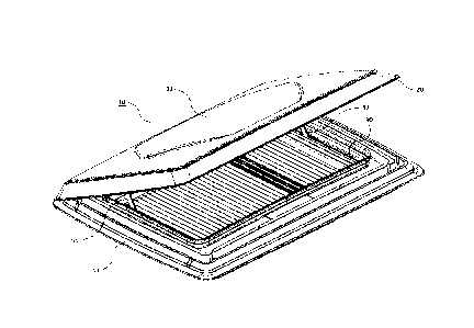
Figure 1 shows an isometric view of an exemplary embodiment of a panel device
according to the invention in a ready-to-use state. The panel device comprises
a frame
with an upper side 11 and a lower side 12, see also figure 2, between which an
edge
part (not shown) of a roof of for instance a recreational vehicle is
receivable. The two
5 parts 11, 12 connect seamlessly to the edge part, wherein the external,
exterior part
11 in particular also seals watertightly onto the edge part. The frame per se
can be
manufactured from various materials which are sufficiently strong and, in
respect of
the external part, are sufficiently weather-resistant. Aluminium or, as in
this
embodiment, an injection-moulded thermoplastic plastic is in this respect
often opted
10 for. In this case use is made of an outer shell of Acrylonitrile styrene
acrylate (ASA)
with a foamed core of polystyrene or polyurethane.
The edge part bounds an opening 15 which is opened up by the panel device. The
panel device comprises for this purpose a window 20 which is formed
substantially by
a flat panel 21 which extends over the opening 15. In this embodiment the
window is
formed entirely from a transparent plastic such as poly(methyl methacrylate)
(PMMA)
or polycarbonate, and thereby allows daylight into the accommodation which
will
eventually be located under the panel device. A blind 30, which is in that
case usually,
as it is here, arranged adjustably in the internal, interior part 12 of the
frame, can
optionally be applied in the frame. The same is optionally the case for a
screen which
can be provided in the frame in similar manner to prevent insects from
entering.
Although use is in this embodiment made of a pleated blind 30, a roller blind
and/or
screen blind can also be applied instead.
On a longitudinal side thereof the window 20 is connected pivotally to the
frame 11,
12. As evident from the exploded view of figure 3, a stay device 50 which
enables a
user to open and close the window is provided in or on the frame. In figure 4
this stay
device is also shown separately for the purpose of elucidation. The stay
device 50
comprises a set of stays 51, 52 on either side of the frame, these extending
at a first,
proximal outer end from a linear guide 61, 62 which is accommodated in the
frame. At
Date Regue/Date Received 2023-04-13
P12139CA00
¨8¨
their opposite, distal outer ends the stays are connected pivotally to the
window 20,
21. The stays 51, 52 are adjustable in the guide 61, 62 between a first
position, in
which the stays heat least substantially flat relative to the guide, and a
second position
in which the stays have taken on a raised state from the guide. The window can
thereby be forced from a closed closing position to an at least partially
opened
pivoting position and vice versa. An energizing thereof will be further
elucidated
below.
This embodiment is based on a manual operation of the window by means of a
crank
40. The crank 40 is connected around a pivot shaft 43 to a bushing 41 which is
provided internally with a toothing which engages on a corresponding external
toothing of a drive shaft 75 of a reel device 70. The reel device is shown in
more detail
in figure 5. The drive shaft 75 is coupled operatively to a toothing on a
rotation shaft
77 of a reel 78 via a worm wheel 76. Owing to the worm wheel transmission 76,
there
is no opposite force transmission from reel 78 to crank 40, which prevents
window 20
from closing unintentionally. This is helped further by the fact that the
crank 40 can be
swung around its pivot shaft 43 such that the knob 45 thereof disappears into
a cavity
provided in the frame for this purpose. This is further illustrated in
respectively
figure 7A and figure 7B. in this way the drive shaft 75 can be fixed in a
position it has
20 taken up, and the window thus blocked.
Instead of the manual operation described here of the reel 77, 78 by means of
a crank
or other operating member, a motorized version can otherwise also be provided,
wherein the action of the crank is taken over by an output shaft of an
electric motor
25 provided in the wall of the frame. In that case the reel 77, 78 is set
into rotation by
energizing the electric motor in question.
Provided between the reel 78 of reel mechanism 70 and the stays 51, 52 is a
flexible
transmission. This transmission comprises a set of flexible pull members in
the form of
steel transmission cables 71, 72, 73 which have each been introduced
individually into
Date Regue/Date Received 2023-04-13
P12139CA00
-9-
a sleeve 81, 82, 83 and are axially movable therein. At their outer end the
pull cables
71, 72, 73 have a fixation member 74 which hooks into a corresponding recess
or
opening in the proximal, first outer end of the stay 51, 52 to which the cable
is
coupled. The two stays 51, 52 slide with the proximal outer end in a linear
guide 61,
62. The stays 51, 52 can thus be pulled reciprocally in guide 61, 62 by this
outer end by
means of the pull cables 71, 72,73 which are connected to these outer ends on
either
side. A free opposite outer end of two of the pull cables 71, 72 is received
on the reel
78. For this purpose this outer end is also provided with a fixation member 74
and the
reel 78 of a corresponding recess or cavity in which the fixation member 74 is
received.
The sleeves 81, 82, 83 are laterally bendable but axially rigid, and are
thereby not
axially compressible, or hardly so. For this purpose the sleeve comprises a
metal wire
which is wound tightly in a spiral and over which a plastic coating or film is
arranged
both externally and internally. The two outer ends of the sleeves are fixed in
the
frame, while the relevant transmission cable 71, 72, 73 remains freely movable
therein. As such, an outer end of the sleeves 81, 82, 83 hits the housing of
the guide
61, 62 of the stay 51, 52 which is coupled to the pull cable 71, 72, 73 which
was
introduced into the sleeve.
in order to open or close the window the crank 40 is operated, whereby the
reel 77 is
set into rotation. The two cables 71, 72 which are received on the reel each
lie on their
own part of the reel and are guided in a helical track provided in the wall of
the reel.
The cables are wound in opposite directions, whereby winding up of the one
cable
simultaneously results in unwinding of the other cable. The reel thereby
provides a
tension in the one pull cable 71 over a length, while the other pull cable 72
is payed
out over the same length. Because the two cables 71, 72 lie enclosed in the
sleeves 81,
82 and the sleeves are in turn fixed at their outer end, this respective
tension and
release is transmitted one-to-one to the coupled outer ends of the stays 51,
52. A
synchronization cable 73, 83 provides here for a transmission of the tension
on the one
Date Regue/Date Received 2023-04-13
P1213BCA00
stay 51 51 to the other stay 52 or vice versa. This transmission takes place
mutatis
mutandis in both rotation directions of the reel 77, 78.
The stay device shown in figure 4 can be accommodated entirely in one of the
two
parts 11, 12 of the frame in particularly practical manner. The external upper
part
therefore comprises in this embodiment internally a tunnel 100 in which the
cable
guide 81-83 can be placed and fixed. Extending transversely of the tunnel 100
is a
ventilation channel which extends in open communication between a set of
external
air inlets 110, 120, see figure 6, and one or more internal air inlets 130,
see figure 2
and 7A, 7B. As in this embodiment, these air openings 110..130 advantageously
lie
distributed over a whole length of the relevant side of the frame in
accordance with a
ventilation gap of the ventilation channel which lies therebetween and which
likewise
extends laterally over a full width or length of the frame. A uniform natural
ventilation
of a space located under the frame is hereby realized, particularly in the
case of a
recreational vehicle when moving.
The movement of the stays in their guides is shown in successive stages in
figures RA-
W, from an at least substantially completely opened position of the window to
a
locked position of the window. The stay is adjustable from the first position
shown in
figure 8A to a fully flat orientation in which the window will be completely
closed.
From this flat orientation, the stay 51 can be pulled further into the guide
61. Finally,
the proximal outer end of stay 51 hits a locking member 53 at the outer end of
guide
61. This third position is shown in figure 8C. This locking member 53 thereby
pivots
about a lock axis 54 around which it is mounted, and falls behind a protrusion
55
provided on the window, see also figures 6, 7A and 7B. A cavity into which the
locking
element falls in that case can optionally also be provided in the window
instead. in
both cases the window is thus hermetically sealed in a closed position of
figure 8C. A
torsion spring or coil spring (not shown) is coupled to the locking member 53
and
produces a counter-tension which releases the locking member 53 from the
protrusion
55, i.e. from the cavity, as soon as the stay 51 is returned to the position
shown in
figures 8A and 8B and thereby releases the locking member 53.
Date Regue/Date Received 2023-04-13
P12139CA00
¨11¨
The invention thus provides a panel device with a particularly compact and
effective
stay device, which can be incorporated in the frame of the panel device in
particularly
practical manner and can furthermore be motorized in relatively simple manner.
Although the invention has been further elucidated above with reference to
only a
single exemplary embodiment, it will be apparent that the invention is by no
means
limited thereto. On the contrary, many variations and embodiments are still
possible
within the scope of the invention for a person with ordinary skill in the art.
The
embodiment is thus based on a window with a fully transparent panel, but the
panel
device can also be embodied with a merely semi-transparent, translucent panel
or
with a fully opaque panel. Instead of a rotating actuator, driven by a crank
or an
electric motor, use can also be made of a translating actuator which imparts
an
optionally linear stroke to both pull cable outer ends coupled thereto. And
instead of a
crank it is also possible to provide a different operating member, such as for
instance a
rotary knob.
Date Regue/Date Received 2023-04-13