Note: Descriptions are shown in the official language in which they were submitted.
CA 03197692 2023-03-31
WO 2022/087463 PCT/US2021/056319
1
SUPPORT JIG AND TEST SPECIMEN HOLDERS USED WITH THE SUPPORT JIG
BACKGROUND
[0001] The discussion below is merely provided for general background
information and is
not intended to be used as an aid in determining the scope of the claimed
subject matter.
[0002] Test specimen holders or grips are well known in the material
testing art and are used
frequently to hold a test specimen in a material testing system. The holder
includes opposed jaws
or wedges that holder the test specimen therebetween. Although such test
specimen holders have
been around for a long time, use of such holders has been confirmed to test
specimens that are
relatively large use on very small test specimens is not known.
[0003] Typical test specimens use geometries that have a minimum length of
25 mm or
greater and cross sections of multiple millimeters x multiple millimeters.
These specimens can
be used in a variety of test specimen holders. The holders are installed in a
force reaction
structure or test machine that applies longitudinal forces along the long axis
of the specimen.
The holders typically have a method of crudely, but repeatably aligning the
test specimen in the
holder and the holders can be aligned to each other easily to ensure low
bending strains as
required by ASTM testing procedures. The holders also require the user to
install the specimen
in the holders while the test machine is actively maintaining position and
load.
[0004] The field of additively manufactured components has required
investigation into the
material properties of the deposition process. This has resulted in specimen
cross section
geometries of less than 1 mm thick and less than 1 mm wide with an overall
length of less than
mm. These specimen sizes do not fit with current specimen holders and there is
no method of
inserting the specimen in the holders in a repeatable fashion. There are also
concerns as the
specimens are so small that requires additional time to install a specimen
thereby exposing the
user to an active machine for a longer duration of time.
SUMMARY
[0005] This Summary and the Abstract herein are provided to introduce a
selection of
concepts in a simplified form that are further described below in the Detailed
Description. This
Summary and the Abstract are not intended to identify key features or
essential features of the
claimed subject matter, nor are they intended to be used as an aid in
determining the scope of the
CA 03197692 2023-03-31
WO 2022/087463 PCT/US2021/056319
2
claimed subject matter. The claimed subject matter is not limited to
implementations that solve
any or all disadvantages noted in the Background.
[0006] Generally, a support jig for use with a testing machine applying
tensile loads jig
includes a frame and a pair of spaced apart supports joined to the frame to
provide an alignment
axis. Each support is configured to releasably hold a test specimen holder on
the alignment axis
in a fixed spatial relationship with ends of the test specimen holders
mountable to the test
machine facing in opposite directions. The support jig can be used with any
type of test specimen
holder including but not limited to the test specimen holders herein disclosed
comprising
separate and additional aspects of the present invention.
[0007] In a one embodiment, the support jig further includes a test
specimen support joined
to the frame between the pair of spaced apart supports. The test specimen
support conveniently
holds the test specimen on the alignment axis so that the test specimen
holders can be secured to
each end of the test specimen. An end of the test specimen support can have a
recess to receive
the test specimen. Preferably, the test specimen support comprises a first
portion joined to the
frame and a second portion having the end. The second portion is adjustably
secured to the first
portion so as to adjust a position of the end orthogonally with respect to the
alignment axis,
which allows test specimens of different widths to be accurately placed on the
alignment axis.
The second portion can be linearly adjustable with respect to the first
portion such as by
telescoping with respect to the first portion.
[0008] Preferably, the pair of supports comprises a first support and a
second support,
wherein at least one support, and preferably both, are adjustably positionable
on the frame to
axially adjust a position of the support(s) on the alignment axis. In a
preferred embodiment, each
support includes a recess or protrusion spaced apart from the alignment axis
that is
complimentary to a protrusion or recess, respectively, provided on the
associated test specimen
holder securable to the support. The complementary engagement of the
protrusion and the recess
orients the test specimen holders about the alignment axis so as to properly
mount to the test
specimen.
[0009] In one embodiment, each support provides a mounting aperture for
receiving a
portion of the test specimen holder. Preferably, each support includes a
removable portion
securable to the end that forms the mounting aperture so as to allow
convenient mounting of each
CA 03197692 2023-03-31
WO 2022/087463 PCT/US2021/056319
3
test specimen holder. The end of each support and the removable portion
include surfaces
engageable with the test specimen holder that are complimentary with the test
specimen holder.
[0010] Another aspect of the present invention is a method of using the
support jig to
remotely mount the test specimen to the test specimen holders from the test
machine, and then
using the support jig to maintain the fixed special relationship while the
test specimen holders
are mounted to the test machine is also disclosed.
[0011] In one embodiment, the method for loading a test specimen in a
tensile test machine
having a first test specimen holder and a second test specimen holder,
includes: providing a
support jig remote from the test machine; mounting the first test specimen
holder and the second
test specimen holder to the support jig so that heads configured to hold ends
of the test specimen
face each other and ends of the test specimen holders securable to the test
machine face in
opposite directions, the test specimen holders being aligned with each other
and located on a
common alignment axis; securing heads of the first and second test specimen
holders to first and
second ends, respectively, of the test specimen; and mounting the first test
specimen holder and
the second test specimen holder in the tensile test machine wherein the
support jig holds the first
test specimen holder and the second test specimen holder on the alignment axis
and in a fixed
spatial relationship relative to each other.
[0012] In a further embodiment, the jig incudes a test specimen support and
the method
further comprises mounting the test specimen to the test specimen support so
as to be aligned
with the alignment axis. Preferably, mounting the test specimen to the test
specimen support so
as to be aligned with the alignment axis occurs before securing the heads of
the first test
specimen holder and the second test specimen holder to the test specimen.
[0013] The jig can include a first support and a second support coupled to
a frame, and
wherein mounting the first test specimen holder and the second test specimen
holder to a support
jig comprises mounting the first test specimen holder to the first support and
the second test
specimen holder to the second support. Mounting the first test specimen holder
and the second
test specimen holder in the tensile test machine can occur after mounting the
first test specimen
holder and the second test specimen holder to the support jig and/or securing
heads of the first
and second test specimen holders to test specimen.
[0014] If desirable, so as to provide proper alignment of the test specimen
holders to each
other so as to hold the test specimen correctly, mounting the first test
specimen holder and the
CA 03197692 2023-03-31
WO 2022/087463 PCT/US2021/056319
4
second test specimen holder to the support jig can include fixing a rotational
position of each of
the first test specimen holder and the second test specimen holder about the
alignment axis.
Preferably, securing heads of the first and second test specimen holders to
first and second ends,
respectively, of the test specimen includes applying a preload clamping
holding force to end of
the test specimen.
[0015] Another aspect of the present invention is a test specimen
comprising a head body
having a first inclined body surface and a second inclined body surface facing
each other. A first
and second wedge are located in the head body, the first wedge having a first
inclined wedge
surface in sliding contact with the first inclined body surface and the second
wedge having a
second inclined wedge surface in sliding contact with the second inclined body
surface. A
support shaft has a first end connectable to a portion of a test machine and a
second end
supporting the first and second wedges. A drive is supported by the support
shaft, the drive being
located between the second end and the first end. A spring is connected to the
head body at a first
end and to the drive at a second end.
[0016] Preferably, the drive is configured to pull the second end of the
spring away from the
head body. The drive can comprise a first portion movable with respect to a
second portion, the
first portion being connected to the second end of the spring and the second
portion engages or is
fixedly joined to a portion of the support shaft. The first portion can moves
axially relative to the
support shaft either with or without rotation about the support shaft.
[0017] The drive can include a driven part in contact with and movable
relative to the first
portion and the second portion. The driven part is movable toward and away
from a longitudinal
axis of the support shaft. Preferably, the drive includes an actuator
supported by the first portion
in contact with the driven part. In one embodiment, the actuator comprises a
drive screw
threadably engaging the first portion.
[0018] Engaging surfaces of the driven part and the second portion can
include at least one
inclined surface on at least one of the driven part and/or the second portion.
Preferably, engaging
surfaces of the driven part and the second portion are each an inclined
surface.
[0019] The drive can include a wall forming a chamber about the support
shaft, the driven
element being disposed in the chamber, the drive can include an end cap joined
to an end of the
wall.
CA 03197692 2023-03-31
WO 2022/087463 PCT/US2021/056319
[0020] In one embodiment, the spring comprises a plurality of longitudinal
spring elements
disposed about the support shaft, preferably as a cylindrical body at least
partially around the
support shaft where the spring elements are integral with the body being
formed from a single
unitary body with longitudinal slots.
[0021] Preferably, at least one of the mount or the head body comprises one
of an aperture
opening to an outer surface and extending inwardly transversely to a
longitudinal axis of the
support shaft or a pin extending away from the outer surface in a direction
transversely from the
longitudinal axis so as to allowing mounting of the test specimen holder to
the support jig.
[0022] Another embodiment of a test specimen holder includes a head body
having a first
inclined body surface and a second inclined body surface facing each other.
First and second
wedges are located in the head body, the first wedge having a first inclined
wedge surface in
sliding contact with the first inclined body surface and the second wedge
having a second
inclined wedge surface in sliding contact with the second inclined body
surface. A mount is
joined to the head body at a first end and has a bore. A support shaft is
disposed in the bore and
has a first end supporting the first and second wedges. A spring urges the
support shaft toward
the head body.
[0023] In one embodiment, the bore includes an inner flange, a first end of
the spring
engaging the support shaft and a second end engaging the inner flange. The
spring can comprise
a compression spring.
[0024] In one embodiment, an adjuster is provided and adjusts a force
urging the support
shaft toward the head body. The adjuster can comprise an actuator joined to
the support shaft.
For example, the actuator can comprise a screw threadably joined to the mount.
[0025] Preferably, a handle is joined to the support shaft and comprises
portions extending in
opposite directions from a longitudinal axis of the support shaft.
[0026] Preferably, at least one of the mount or the head body comprises one
of an aperture
opening to an outer surface and extending inwardly transversely to a
longitudinal axis of the
support shaft or a pin extending away from the outer surface in a direction
transversely from the
longitudinal axis so as to allowing mounting of the test specimen holder to
the support jig.
CA 03197692 2023-03-31
WO 2022/087463 PCT/US2021/056319
6
BRIEF DESCRIPTION OF THE DRAWINGS
[0027] FIG. 1 is a perspective view of a test machine.
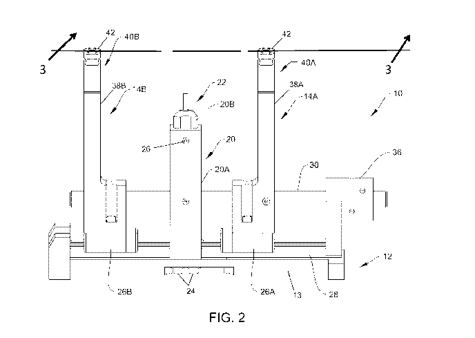
[0028] FIG. 2 is a perspective view of a support jig.
[0029] FIG. 3 is a sectional view of the support jig taken along lines 3--3
in FIG. 2.
[0030] FIG. 4 is a front side elevational view of a test specimen holder.
[0031] FIG. 5 is a right-side elevational view of the test specimen holder
of FIG. 4.
[0032] FIG. 6 is a top plan view of the test specimen holder of FIG. 4.
[0033] FIG. 7 is a sectional view of the test specimen holder taken along
lines 7--7 of FIG. 6.
[0034] FIG. 8 is a sectional view of the test specimen holder taken along
lines 8--8 of FIG. 6.
[0035] FIG. 9 is an exploded view of the test specimen holder of FIG. 4.
[0036] FIG. 10 is a mount for the test specimen holder of FIG. 4.
[0037] FIG. 11 is a handle for the test specimen holder of FIG. 4.
[0038] FIG. 12 is an exploded view of a portion of the test specimen holder
of FIG. 4.
[0039] FIG. 13 is a perspective view of a second embodiment of a test
specimen holder.
[0040] FIG. 14 is a sectional view of the test specimen holder taken along
lines 14--14 of
FIG. 13.
[0041] FIG. 15 is a sectional view of the test specimen holder taken along
lines 15--15 of
FIG. 13.
[0042] FIG. 16 is an exploded view of the test specimen holder of FIG. 13.
[0043] FIGS. 17 - 19 are exploded views of portions of the test specimen
holder of FIG. 13.
[0044] FIG. 20 - 22 are perspective views of test specimen holders mounted
to the support
jig.
[0045] FIG. 23 is an elevational view of the test specimen holders and
support jig installed in
the test machine.
DETAILED DESCRIPTON
[0046] A material testing system 1 for applying force loads to a test
specimen is illustrated
in FIG. 1. The system 1 typically would include an upper test specimen holder
and an identical
lower test specimen holder both of the type illustrated and described below.
The test specimen
holders hold a test specimen along a longitudinal axis 2. In the embodiment
illustrated, the lower
CA 03197692 2023-03-31
WO 2022/087463 PCT/US2021/056319
7
test specimen holder is connected to an actuator 3 through which force loads
are applied to the
test specimen and reacted against a reaction structure generally indicated at
4.
[0047] In the exemplary embodiment illustrated, although other
configurations are known
and can be used with aspects of the invention described below, the material
testing
system 1 includes a frame 5 having a base 6. A pair of support members 7
extends upwardly
from the base 6 and are joined together by a crossbeam 8 which provides a
stable support
surface. A pair of support columns 8A extends upwardly from the crossbeam 8 to
a crosshead 8B
movable on the support columns 8A. A load cell 9 can join the upper test
specimen holder to the
crosshead 8B, as illustrated, or can join the lower test specimen holder to a
rod of the actuator 3.
As is known in the art, the load cell 9 provides a signal indicative of
tension or compression
forces applied to the test specimen. The crosshead 8 and the support columns
8A provide the
reaction structure. Hydraulic lifts 8C move the crosshead 8 to selectively
fixed positions.
[0048] Generally, among other aspects, a test specimen holder 100, 200
(Figs. 4-19) is
described capable of through zero fatigue loading, tension loading, and
compression loading of
miniature and sub-miniature test specimens of both flat and round geometries.
The test specimen
holder 100, 200 works in conjunction with a specimen insertion or support jig
10 (Figs. 2, 3 and
20-23) that has the purpose of allowing specimen insertion to happen on a
workbench or table
remotely from the test machine 1. The support jig holds the specimen holders
100, 200 rigidly
and accurately so that bending strains on the specimen inherent to the
installation process are
limited and repeatable. The support jig 10 provides a method of introducing
clamping forces into
the specimen holders 100, 200 while not applying errant load to the specimen.
The support jig 10
allows the user to verify the installation accuracy, and allows the
installation of the jig/specimen
holder sub-system to be installed into the test machine 1 without errant loads
being applied to the
test specimen until such time that the test machine 1 is in control and
managing loads and
displacements.
[0049] An aspect of the disclosure is the support jig 10 (Figs. 2, 3 and 20-
23) that is used to
mount a test specimen 15 to test specimen holders or grips 100, 200 so as to
be accurately
positioned in the holders 100, 200 without undesired loading, which can damage
or break the test
specimen 15 as well as aligning the test specimen 15 with axes of the test
specimen holders 100,
200 so as to perform required testing in the testing machine 1. The support
jig 10 allows loading
the test specimen 15 to the test specimen holders 100, 200 in an accurate and
repeatable manner.
CA 03197692 2023-03-31
WO 2022/087463 PCT/US2021/056319
8
[0050] With the test specimen 15 loaded in the test specimen holders 100,
200, and the test
specimen holders 100, 200 secured to the jig 10, the complete assembly
comprising the test
specimen holders 100, 200, support jig 10 and test specimen 15, as illustrated
in Fig. 22, can be
transferred to the test machine 1 (Fig. 23), such the test machine 1 described
above, can be used
to impart forces and/or displacements to the test specimen 15. Such test
machines are known in
the art as a tension or tensile tester (used for applying monotonic or single
directions loads) or a
tension/compression tester (which can be used in fatigue testing where
alternating tension and
compression loads can be applied). If desired, a rotational actuator, not
shown, can be part of the
test machine 1 with or without the linear actuator 3. The support jig 10
allows the test specimen
holders 100, 200 and the test specimen 15 attached between the holders 100,
200 to be loaded
into the test machine 1 without causing breakage of the test specimen 15
because all loads
between the test specimen holders 100, 200 are transferred through the support
jig 10 rather than
through the test specimen 15. When the test specimen holders 100, 200 have
been secured in the
test machine 1, the jig 10 can be detached from the test specimen holders 100,
200 so that testing
can commence.
[0051] Referring to Figs. 2 and 3, the support jig 10 includes a frame 12
having a base 13. A
pair of spaced-apart supports 14A, 14B is joined to the base 13. Each support
14A, 14B is
configured to releasably hold a test specimen holder on an alignment axis 16
(Fig. 20). A test
specimen support 20 is joined to the frame 12 between the pair of spaced-apart
supports 14A,
14B. The test specimen support 20 has an end 22 configured to hold the test
specimen 15 on the
alignment axis 16.
[0052] The test specimen support 20 includes a first portion 20 joined to
the base 13 or frame
12 and a second portion 20B having the end 22. The second portion 20B is
adjustably secured to
the first portion 20A so as to adjust a position of the end 22 orthogonally
with respect to the
alignment axis 16. Preferably the second portion 20B is linearly adjustable
with respect to the
first portion 20A. In the embodiment illustrated, the second portion 20B
telescopes with respect
to the first portion 20A. The end 22 can include a recess of size and shape to
hold the test
specimen 15 on the alignment axis 16. A holding device such as a clip, clamp,
tape, straps or the
like can be provided on the end 22 if desired to aid in holding the test
specimen 15 to the end 22.
Fasteners 24 secure the test specimen support 20 to the frame 12, while a
fastener 26 such as a
CA 03197692 2023-03-31
WO 2022/087463 PCT/US2021/056319
9
setscrew can be used to fix the second portion 20B at a desired position with
respect to the first
portion 20A.
[0053] The pair of supports 14A, 14B preferably are adjustable on the frame
12 axially or
parallel to the alignment axis 16 so as to adjust a position of supports 14A,
14B relative to the
test specimen support 20. Preferably, each of the supports 14A, 14B is
adjustably positionable on
the frame 12, being mounted on a linear bearing support 26A, 26B,
respectively. In a preferred
embodiment, each linear bearing support 26A, 26B is mounted to a linear rail
28 with no
backlash (vertical backlash in the illustrated embodiment) such that only
linear movement along
the rail 28 is possible.
[0054] In the embodiment illustrated, the frame 12 includes an optional
alignment guide 30.
Each of the supports 14A, 14B is supported by the rail 28, but the guide 30
defines the
orientation of the alignment axis 16 wherein the alignment axis 16 in effect,
remains parallel to
the guide 30. Preferably, each of the supports 14A, 14B and the test specimen
support 20 include
a bore 34A, 34B, 34C, respectively, so as to receive the guide 30. The guide
30 is held in a
stationary position with respect to the base 13 by a standoff 36, which in the
embodiment
illustrated, also includes a bore 38 to receive an end of a guide 30 while
fasteners such as set
screws 40 fix the guide 30 to the standoff 36.
[0055] The supports 14A, 14B move linearly with respect to the rail 28
being guided by
guide 30 so as to remain in proper alignment. Once the test specimen holders
100, 200 have been
mounted in each respective support 14A, 14B, and the test specimen 15 is
mounted to each of the
holders 100, 200, the supports 14A, 14B are fixedly secured to the guide 30
each with a
corresponding fastener 33. In the embodiment illustrated, each fastener
comprises a set screw for
securing the position of each support 14A, 14B on the guide 30. In Fig. 2, set
screw 33 secures
support 14A to guide 30, while support 14B includes a similar set screw, which
is on a backside
of support 14B in Fig. 2. Likewise a fastener such as set screw 35 is used to
secure the test
specimen support 20 to the guide 30.
[0056] It should be noted that use of the guide 30 is not a requirement. In
particular, the
guide 30 is not necessary if the supports 14A, 14B and test specimen support
20 can be secured
to rail 28 such that alignment of the supports 14A, 14B and test specimen
support 20 are suitably
aligned with each other along the alignment axis 16.
CA 03197692 2023-03-31
WO 2022/087463 PCT/US2021/056319
[0057] Herein disclosed are two different test specimen holders 100, 200
comprising other
aspects of the invention. The test specimen holder 100 is generally used in
tensile testing, but can
be used also in fatigue testing at lighter loads. The test specimen 200 is
particularly well suited
for fatigue testing. Each test specimen holder 100, 200 can be used with the
support jig 10. Each
test specimen holder 100, 200 is releasably secured to each corresponding
support 14A, 14B.
Generally, each of the test specimen holders 100, 200 described below
comprises a base or
mount 102, 202 and a head body 104, 204 secured to the mount 102, 202 (Figs. 4
and 14). The
mount 102, 202 typically comprises a cylindrical member that can be inserted
into corresponding
recess provided in the test machine 1, such as a grip, and secured therein.
The head body 104,
204 includes wedges that are used to hold an end of the test specimen 15
during testing.
[0058] In the embodiment illustrated, the supports 14A, 14B are releasably
secured to the
mounts 102, 202 of each of the test specimen holders 100, 200; however, it
should be noted, if
desired, the supports 14A, 14B can be configured to releasably secure to each
of the head body
104, 204 of the test specimen and holders 100, 200.
[0059] Each support 14A, 14B includes a mounting aperture configured to
receive a portion
of the test specimen holder 100, 200. In the embodiment illustrated, the
mounting aperture is
formed from a portion 40A, 40B, respectively, removably secured to an end 38A,
38B of each
support 14A, 14B. Surfaces of the removable portions 40A, 40B and the ends
38A, 38B together
engage surfaces of the test specimen holders 100, 200. Fasteners 42 secure
each removable
portion 40A, 40B to its corresponding end 38A, 38B.
[0060] For test specimens having generally flat ends to which the test
specimen holders 100,
200 are attached require that the test specimen holders 100, 200 be properly
oriented about the
alignment axis 16 so as to coincide with and properly engage the ends of the
test specimen 15.
[0061] Since typically the test specimens have ends that are coplanar with
each other, each of
the test specimen holders 100, 200 should be oriented in the same position
with respect to each
other so as to orient each of the test specimen holders 100, 200 in their
proper position. The
supports 14A, 14B and holders 100, 200 include a protrusion-aperture
connection between the
supports 14A, 14B and the test specimen holders 100, 200 so as to align and
also hold the test
specimen holders 100, 200 in their proper rotational positions about the
alignment axis 16. In the
embodiment illustrated, the protrusion comprises a pin 50 (Fig. 3). The pin 50
can be securely
fixed in the support 14A, 14B such as in the removable portion 40A, 40B
and/or, as illustrated,
CA 03197692 2023-03-31
WO 2022/087463 PCT/US2021/056319
11
in the end 38A, 38B of each support 14A, 14B. With the supports 14A, 14B
having the
protrusions or pins 50, the test specimen holders 100, 200 include
corresponding apertures 101,
201 of size to receive a pin 50. In an alternative embodiment, the protrusion
such as a pin, can be
disposed on the test specimen holder 100, 200 wherein then the aperture would
be provided on
the supports 14A, 14B.
[0062] Figs. 4 - 12 illustrate the test specimen holder 100. Generally, the
test specimen
holder 100 includes the mount or base 102 and the head body 104 secured to an
end of the mount
102. At an end opposite the head body 104, the mount 102 is inserted into a
corresponding recess
provided in the test machine 1, which could comprise another, larger test
specimen holder.. A
stop-collar 106 limits how far the mount 102 is inserted into the test machine
1.
[0063] As indicated above, it is preferable that the test specimen holder
100 be positioned in
the support jig 10 where its rotational position is fixed in an accurate and
repeatable manner. The
protrusion-aperture described above can be used. In the embodiment
illustrated, the protrusion
herein comprising the pin 50 is secured to each of the supports 14A, 14B,
while the aperture 101
resides in the mount 102.
[0064] Generally, the test specimen holder 100 includes movable wedges 120
that are
supported by and slide on a support plate 118. Each of the wedges 120 has a
specimen engaging
face that faces the other wedge and engages the test specimen 15. In the
embodiment illustrated,
the wedges 120 are planar for use with flat test specimens; however this
should not be considered
limiting in that the wedges 120 can be configured to hold test specimens
having other shapes
such as test specimens having cylindrical ends, where for example, the wedges
120 would
include notches. Together the wedges 120 engage the test specimen 15 from
opposite sides.
Each wedge 120 includes an inclined back surface 122. Inclined surfaces 124 of
a head body 104
engage the inclined back surfaces 122 of each wedge 120 and drive or urge the
wedges 120
toward each other with relative displacement between the head body 104 and the
wedges 120.
The use of such wedges in a head body is well-known and thus will not be
further described, but
it should be noted that although two wedges 120 are shown in the exemplary
embodiment a
single wedge or three or more wedges can be used, where each wedge commonly
would engage
the inclined surface 122 on the head body 104.
[0065] Springs 130 are attached to the wedges 120 and have a spring bias
that drives or urges
the wedges 120 away from each other so as to create a space and allow easy
insertion of the ends
CA 03197692 2023-03-31
WO 2022/087463 PCT/US2021/056319
12
of the test specimen 15 between wedges 120. In the embodiment illustrated,
each of the springs
130 comprise a torsion spring having one end insertable into a recess or
aperture 132 (Fig. 12)
provided in the wedge 120 while the other end is fixedly retained by the head
body 104, herein
with an opposite end received in a recess or aperture 134 (Fig. 8).
[0066] The support plate 118 for the wedges 120 is mounted to a support rod
or shaft 140
that extends downwardly away from the head body 104. The support plate 118
includes
upstanding sides or edges that maintain the orientation of the wedges 120 so
as to generally face
each other but allow movement of the wedges 120 on the support plate 118
towards and away
from each other. The test specimen holder 100 includes a bias spring 142 that
generally biases
the support shaft 140 upwardly towards the head body 104 so as to urge the
wedges 120 towards
each other and to engage the end of the test specimen located therebetween.
The bias spring 142
herein is a coil spring received in a bore 144 provided in the mount 102. The
support shaft 140
includes an extending portion 146 having a width allowing it to be inserted
into the coils
provided in the bias spring 142. A flange 148 is provided in the support shaft
140 that engages
the uppermost coil of the bias spring 142.
[0067] A handle 150 secured to the support shaft 140 allows the support
shaft 140 to be
pulled away from the head body 104 and against the bias spring 142 so as to
allow the wedges
120 to open due to the spring force provided in the springs 130 that urge the
wedges 120 away
from each other. In the embodiment illustrated, the handle 150 has portions
152 that extend in
opposite directions through slots 154 provided in the mount 102. The handle
portions 152 are
secured to the support shaft 140 where the support shaft 140 includes a bore
156 of size to
receive a handle shaft 158 therein. Generally the forgoing design allows the
handle 150 to be
pulled downwardly away from the head body 104 where the torsion springs 130
thereby urge the
wedges 120 away from each other so as to allow the test specimen end to be
insert therebetween.
When the handle 150 is released, a clamping force is generated and applied to
the end of the test
specimen 15.
[0068] In the embodiment illustrated, a preload clamp force adjuster 160
(Figs. 6, 7) is
provided to apply a force that further urges the wedges 120 toward each other
so as to apply a
preload clamping force upon the end of the test specimen 15. The adjuster 160
includes an
actuator 162 that urges the support shaft 140 toward the head body 104 so as
to urge the wedges
CA 03197692 2023-03-31
WO 2022/087463 PCT/US2021/056319
13
120 toward each other. The adjuster 160 comprises a drive screw that abuts the
end of the shaft
140 and is threadably connected to a threaded bore in the mount 102.
[0069] The test specimen 15 is secured to the test specimen holder 100 in
two steps. First, the
handle 150 is pulled down against the bias spring 142, which causes the wedges
120 to separate
allowing the test specimen 15 to be located between the wedges 120. When the
handle is
released, the wedges 120 contact and hold the test specimen 15 from the force
provided by the
bias spring 142. The actuator 160 is then operated, herein by rotation of it
being a drive screw to
further urge the shaft 146 toward the head 104, thereby driving the wedges 120
toward each
other and against the test specimen 15.
[0070] The second test specimen holder 200 is illustrated in FIGS. 13 - 19.
The test specimen
holder 200 includes the mount 202 and head body 204 and wedges 220. The wedges
220 and
head body 204 operate in the same manner as wedges 120 and head body 104 where
inclined
back surfaces on the wedges 220 slide upon inclined surfaces in the head body
204 so as to cause
transverse movement of the wedges 220 toward each other.
[0071] The mount 202 is connected to a support shaft 240 on a first end
240A with a fastener
203, while a second end 240B supports the first and second wedges 220. A drive
210 supported
by the support shaft is located between the first end 240A and the second end
240B. A spring
212 is connected, for example threadably, to the head body 204 at a first end
and to the drive
210, for example threadably, at a second end to cylindrical a first portion
214.
[0072] The drive 210 is configured to pull upon the spring 212 so as to
displace the head 204
downward axially relatively to the shaft 240. Downward movement of the head
204 urges the
wedges 220 toward each other. The test specimen 15 is secured to the test
specimen holder 200
also in two steps. First with the threaded connection between the spring 212
and the first portion
214 at a minimum so as to allow the head 204 to be displaced upwardly away
from the end of the
shaft 240, the wedges 220 are sufficiently away from each other to allow the
test specimen to be
inserted between the wedges 220. Springs 223 urge the wedges 220 against the
inclined surfaces
of the head 204 so as to cause the wedges 220 create a space so as to allow
insertion of the test
specimen 15. In this embodiment, each of the springs 223 are elongated with a
first end fixedly
joined to the support shaft 240 and second end to the wedge 220.
[0073] The first portion 214 is then rotated about the shaft 240 so as to
increase the threaded
connection between the first portion 214 and the spring 212. This pulls the
spring 212 and head
CA 03197692 2023-03-31
WO 2022/087463 PCT/US2021/056319
14
downwardly so that the wedges 220 are urged toward each other and against the
test specimen
15, where the spring 212 provides a spring force.
[0074] To further increase the clamping force of the wedges 220 the drive
210 includes an
actuator or displacement mechanism to further displace the first portion 214
axially downwardly.
The actuator mechanism includes a driven part 228 in contact with and moveable
relative to the
first portion 214 and a second portion 216. In the embodiment illustrated, the
driven part 228 is
moveable, herein transversely, toward and away from a longitudinal axis of the
support shaft
240. An actuator 230 supported by the first portion 214 is in engaging contact
with the driven
part 228. The actuator 230 moves toward and away from the longitudinal axis,
preferably being
arranged transversely with respect thereto. In the embodiment illustrated, the
actuator 230 can
comprise a drive screw threadably engaging the first portion 214. Engaging
surfaces of the
driven part 228 and second portion 216 include an inclined surface on at least
one of the driven
part 228 and/or second portion 216, and in a preferred embodiment, each of the
driven part 228
and the second portion 216 include inclined surfaces engaging each other. A
wall 234 can form a
chamber 236 about the support shaft 240 wherein the driven part 228 and second
portion 216 are
disposed in the chamber 236. An end cap 238 is joined to an end of the wall
234 so as to capture
the driven part 228 and second portion 216 in the chamber 236 and maintain the
driven part 228
in contact with the second portion 216. The second portion 216 can be fixedly
secured to the
support shaft 240 and in one embodiment being integrally formed therewith
being formed from a
single unitary body. In an alternative embodiment, as illustrated, the second
portion 216 is
separable from the support shaft 240 and can comprise a disc shaped element
having an aperture
216A through which a portion 240A of the support shaft 240 extends
therethrough. In such a
configuration, the second portion 216 engages an annular flange 240B provided
on the support
shaft 240 so as to provide a reaction structure.
[0075] With the second portion 216 comprising a disc element, the driven
part 228 can also
be formed as a disc having an aperture 228A through which the portion 240A of
the support
shaft 240 extends therethrough. The aperture 228A, however, comprises a slot
with a
longitudinal axis being transverse to the longitudinal axis of the support
shaft 240. The slotted
aperture 228A allows the driven element 228 to move transversely with respect
to the
longitudinal axis of a support shaft 240. In the embodiment illustrated, the
actuator 230
comprises two separate actuators 230A, 230B wherein a first actuator 230A
drives the driven
CA 03197692 2023-03-31
WO 2022/087463 PCT/US2021/056319
part in the direct indicated by arrow 250A while a second actuator 230B is
used to drive the drive
element 228 in the opposite direction by arrow 250B. One or both of the
actuators 230A, 230B
can comprise a threaded element threadably engaging the first portion 214.
[0076] To increase the clamping force of the wedges 220 upon the test
specimen 15, the
actuator 230 is operated to displace the driven element 228. In the embodiment
illustrated due to
the inclined surfaces on the second portion 216 and driven element 228,
movement of the
actuator 230B in the direction of arrow 250B further displaces the cylindrical
first portion 214
downwardly with respect to the shaft 240, thereby increasing the tension in
the spring 212 and
pulling the head 204 downwardly. When the test specimen is to be removed, the
actuator 230B is
moved in the direction of arrow 250A, and then the actuator 230A is also
operated to drive the
driven element 228 in the direction of arrow 250A, allowing the cylindrical
portion 214 to move
axially upwardly. The cylindrical portion 214 can then be rotated to minimize
the threaded
connection of the spring and the cylindrical portion 214 sufficiently so the
wedges 220 separate
and allow removal of the test specimen 15.
[0077] Referring to Fig. 17, the spring 212 can comprise a plurality of
longitudinal spring
elements disposed about the support shaft 240. In the embodiment illustrated,
the spring 212
comprises a cylindrical body having longitudinal slots 212A wherein the spring
elements are
portions 212B of the cylindrical body located between successive longitudinal
slots 212A. In one
embodiment, the spring 212 is threadably joined to the head body 204 at a
first end 212C and
threadably joined to the drive 210 at a second end 212D.
[0078] Like the test specimen holder 100 described above, the aperture 201
is provided to
receive the pin 50 of the support jig 10. The pin 50 can be disposed between
two successive
longitudinal spring elements such as being disposed through one of the slots
212A provided in
the cylindrical body.
[0079] A method of using the test specimen holders, such as but not limited
to holders 100,
200, with the support jig 10 comprises preferably, positioning the support jig
10 on a work
surface remote from the test machine 1; securing the selected specimen holders
to the supports
14A, 14B, preferably using the protrusion-aperture connection between the
specimen holders and
the supports 14A, 14B; locating the test specimen 15 in the specimen holders,
herein with the
exemplary holders 100, 200 by opening the corresponding wedges of each of the
test specimen
holders 100, 200 so as to locate ends of the test specimen 15 between the
wedges. After the test
CA 03197692 2023-03-31
WO 2022/087463 PCT/US2021/056319
16
specimen 15 is mounted to each of the specimen holders and the supports 14A,
14B have been
secured to the jig 10 so that all or substantially all force loads between the
specimen holders 100,
200 are transferred through the jig 10, thereby protecting the test specimen
15 from seeing such
forces, the specimen holders 100, 200 can be mounted in the test machine 1,
and once secured,
the support jig 10 can then be removed.
[0080] In one embodiment, the method further includes allowing the supports
14A, 14B to
move freely on the frame 12 of the support jig 10 during loading of the
specimen end, and then
securing the support 14A, 14B in a fixed position relative to the frame of the
support jig 10, or to
the optional guide 30.
[0081] With reference to Fig. 20 and the test specimen holders 100,
installing the test
specimen 15 is as simple as placing it in one of the holders 100, while
opening the wedges 120
with the handle 150, and releasing the wedges 120 on the test specimen 15 as
illustrated in Fig.
21. The test specimen holder 100 is brought toward the other end of the test
specimen 15 and
secured to it in the same manner to achieve the setup shown in Fig. 22. Each
actuator 160 of each
holder 100 is then operated so as to increase the clamp forces upon the test
specimen 15 as well
as provide a solid load path from the wedges 120 to the mount 102. The test
specimen 15 is now
installed in the holders 100. The set screws of the supports 14A and 14B can
be operated so as to
secure the supports 14A and 14B to the rail 28 and/or the guide 30, if
provided. Specimen
alignment in the test specimen holders can be verified through various means-
mechanical
measurement, optical measurement via light/shadow, lasers, and cameras. Other
means of
verification like photo elastic paint could also be used.
[0082] Referring to Fig. 23, the jig 10 with the specimen holders (e.g.
100) and test specimen
15 are transferred to the test machine 1. In Fig. 23, optional intermediate
holders 280, 282 are
used. In the embodiment illustrated, the upper test specimen holder is mounted
to the load cell 9
that in turn is mounted to intermediate holder 280, the intermediate holder
280 being mounted to
an actuator if present in the crosshead 8, or to the crosshead 8 directly.
Similarly, the lower
specimen test holder is mounted to lower intermediate holder 282 that is
mounted to the actuator
3 or to a test machine base through a load cell if provided.
CA 03197692 2023-03-31
WO 2022/087463 PCT/US2021/056319
17
[0083] In the exemplary test machine 1 of Fig. 23, one mount of the test
specimen holders
100 is installed in the test machine 1 for example with a direct connection
via a clevis pin to the
load cell 9. After installing one end, the test machine 1 can be operated so
as to position the other
end, for example, having grip 282 so as to grasp the end of the other test
specimen holder 100.
After mounting, preferably, the test machine 1 is placed in force control and
operated so that zero
force is being applied between the test specimen holders 100. With zero force
applied, the jig 10
can then be removed and the test machine 1 is now ready to conduct a test upon
the test
specimen. Reverification of specimen alignment in the test specimen holders
can again be
verified through various means-mechanical measurement, optical measurement via
light/shadow,
lasers, and cameras. Other means of verification like photo elastic paint
could also be used.
[0084] Although the subject matter has been described in language directed
to specific
environments, structural features and/or methodological acts, it is to be
understood that the
subject matter defined in the appended claims is not limited to the
environments, specific
features or acts described above as has been held by the courts. Rather, the
environments,
specific features and acts described above are disclosed as example forms of
implementing the
claims.