Note: Descriptions are shown in the official language in which they were submitted.
SYSTEMS AND METHODS FOR CONTROLLING NOISE IN AIRCRAFT POWERED BY
HYBRID-ELECTRIC GAS TURBINE ENGINES
TECHNICAL FIELD
[0001] This disclosure relates generally to hybrid-electric gas turbine
engines for aircraft and
more particularly to systems and methods for controlling noise in aircraft
powered by hybrid-
electric gas turbine engines.
BACKGROUND OF THE ART
[0002] Noise generated by aircraft operations can have an undesirable impact
on residents of
communities in proximity to airports and urban centers. Gas turbine engines,
in particular, may
be a substantial source of aircraft noise, particularly during aircraft
takeoff and landing operations.
Aircraft noise regulations frequently require the strict procedural compliance
during aircraft
operations and may also require demonstration of compliance with applicable
noise standards
during aircraft certification processes. One option for reducing noise
associated with gas turbine
engines, is to reduce gas turbine engine power during certain flight
conditions. However,
sufficient propulsive capability must be maintained in order to satisfy
aircraft performance and
safety requirements. Accordingly, the capability of reducing aircraft noise in
this manner may be
limited. What is needed, therefore, are improved systems and methods for
reducing aircraft noise
without unduly restricting gas turbine engine propulsion.
SUM MARY
[0003] It should be understood that any or all of the features or embodiments
described herein
can be used or combined in any combination with each and every other feature
or embodiment
described herein unless expressly noted otherwise.
[0004] According to an aspect of the present disclosure, a method for
controlling noise emitted
by a hybrid-electric gas turbine engine for an aircraft during a takeoff
flight condition includes
applying a first total rotational force to a shaft with a turbine and an
electric motor. The first total
rotational force includes a first electric rotational force applied by the
electric motor and a first
thermal rotational force applied by the turbine. The first total rotational
force has a first rotational
force ratio of the first electric rotational force to the first thermal
rotational force. The method
1
Date Recue/Date Received 2023-05-02
further includes controlling the noise emitted by the gas turbine engine by
reducing the first
rotational force ratio from an initial rotational force ratio of the
rotational force ratio as an altitude
of the aircraft increases and maintaining the first total rotational force
substantially constant while
reducing the rotational force ratio.
[0005] In any of the aspects or embodiments described above and herein,the
initial rotational
force ratio may be at least 1:1.
[0006] In any of the aspects or embodiments described above and herein, the
initial rotational
force ratio may be between 1:1 and 2:1.
[0007] In any of the aspects or embodiments described above and herein, the
initial rotational
force ratio may be at least 2:1.
[0008] In any of the aspects or embodiments described above and herein, the
step of controlling
the noise emitted by the gas turbine engine may be performed during a first
stage of the takeoff
flight condition. The takeoff flight condition may include a second stage
which is subsequent to
the first stage. The method may further include applying a second total
rotational force to the
shaft with the turbine and the electric motor during the second stage. The
second total rotational
force may include a second electric rotational force applied by the electric
motor and a second
thermal rotational force applied by the turbine. The second total rotational
force may have a
second rotational force ratio of the second electric rotational force to the
second thermal rotational
force. The first total rotational force may be greater than the second total
rotational force.
[0009] In any of the aspects or embodiments described above and herein, the
first rotational force
ratio may include a final rotational force ratio of the first stage and the
final rotational force ratio
may be different than the second rotational force ratio.
[0010] In any of the aspects or embodiments described above and herein, the
method may further
include driving a propeller with the shaft.
[0011] In any of the aspects or embodiments described above and herein, the
step of controlling
the noise emitted by the gas turbine engine may further include adjusting a
pitch of a plurality of
propeller blades of the propeller.
[0012] According to another aspect of the present disclosure, a hybrid-
electric gas turbine engine
for an aircraft includes a shaft, a turbine, an electric motor, and a
controller. The shaft is rotatable
2
Date Recue/Date Received 2023-05-02
about a rotational axis of the gas turbine engine. The turbine is configured
to be driven by a flow
of combustion gases through the gas turbine engine. The turbine is configured
to apply a first
thermal rotational force to the shaft. The electric motor is configured to
apply a first electric
rotational force to the shaft. The first thermal rotational force and the
first electric rotational force
define a first rotational force ratio of the first electric rotational force
to the first thermal rotational
force. The first thermal rotational force and the first electric rotational
force further define a first
total rotational force. The controller includes memory having instructions
stored therein which,
when executed by the controller, cause the controller to control the noise
emitted by the gas
turbine engine by: reducing the first rotational force ratio from an initial
rotational force ratio as an
altitude of the aircraft increases and maintaining the first total rotational
force substantially
constant while reducing the first rotational force ratio.
[0013] In any of the aspects or embodiments described above and herein, the
initial rotational
force ratio may be at least 1:1.
[0014] In any of the aspects or embodiments described above and herein, the
initial rotational
force ratio may be between 1:1 and 2:1.
[0015] In any of the aspects or embodiments described above and herein, the
gas turbine engine
may be a turboprop engine. The shaft may be configured to drive a propeller of
the gas turbine
engine.
[0016] In any of the aspects or embodiments described above and herein, the
propeller may
include a plurality of propeller blades. The propeller may further include an
actuator system
configured to adjust a pitch of the plurality of propeller blades.
[0017] In any of the aspects or embodiments described above and herein, the
turbine may include
a power shaft configured to be selectively coupled with the shaft to apply the
first thermal rotational
force to the shaft.
[0018] In any of the aspects or embodiments described above and herein, the
electric motor may
include a clutch configured to selectively couple the power shaft with the
shaft.
[0019] In any of the aspects or embodiments described above and herein, the
controller may be
an electronic engine controller (EEC).
3
Date Recue/Date Received 2023-05-02
[0020] According to another aspect of the present disclosure, a method for
controlling noise
emitted by a hybrid-electric gas turbine engine for an aircraft during a
takeoff flight condition
includes applying a first total rotational force to a shaft with a turbine and
an electric motor during
a first stage of a takeoff flight condition. The first total rotational force
includes a first electric
rotational force applied by the electric motor and a first thermal rotational
force applied by the
turbine. The first total rotational force has a first rotational force ratio
of the first electric rotational
force to the first thermal rotational force. The method further includes
applying a second total
rotational force to the shaft with the turbine and the electric motor during a
second stage of the
takeoff flight condition, subsequent to the first stage. The second total
rotational force includes a
second electric rotational force applied by the electric motor and a second
thermal rotational force
applied by the turbine. The second total rotational force has a second
rotational force ratio of the
second electric rotational force to the second thermal rotational force. The
method further
includes controlling the noise emitted by the gas turbine engine by adjusting
the first electric
rotational force and the second electrical rotational force of the electric
motor such that the first
total rotational force is greater than the second total rotational force and
the first rotational force
ratio is different than the second rotational force ratio.
[0021] In any of the aspects or embodiments described above and herein, the
aircraft may have
a first average climb gradient the first stage and a second average climb
gradient during the
second stage, the first average climb gradient greater than the second average
climb gradient.
[0022] In any of the aspects or embodiments described above and herein, the
second rotational
force ratio is greater than the first rotational force ratio.
[0023] In any of the aspects or embodiments described above and herein, the
method may further
include driving a propeller with the shaft. The step of controlling the noise
emitted by the gas
turbine engine may further include adjusting a pitch of a plurality of
propeller blades of the
propeller such that the plurality of propeller blades have a first pitch in
the first stage and a second
pitch in the second stage, and the first pitch is different than the second
pitch.
[0024] According to another aspect of the present disclosure, a method for
controlling noise
emitted by a hybrid-electric gas turbine engine for an aircraft includes
applying a thermal rotational
force to a shaft with a turbine of the gas turbine engine operating at an
operational power. The
gas turbine engine has a predetermined minimum operational power level for a
current flight
condition of the aircraft. The method further includes applying an electric
rotational force to the
4
Date Recue/Date Received 2023-05-02
shaft with an electric motor and reducing noise emitted by the gas turbine
engine by reducing the
operational power of the turbine below the predetermined minimum operational
power level for
the current flight condition while the electric motor applies the electric
rotational force to the shaft.
[0025] The present disclosure, and all its aspects, embodiments and advantages
associated
therewith will become more readily apparent in view of the detailed
description provided below,
including the accompanying drawings.
DESCRIPTION OF THE DRAVVINGS
[0026] FIG. 1 illustrates a schematic view of a gas turbine engine, in
accordance with one or more
embodiments of the present disclosure.
[0027] FIG. 2 illustrates an approach trajectory profile for an aircraft, in
accordance with one or
more embodiments of the present disclosure.
[0028] FIG. 3 illustrates an approach trajectory profile for an aircraft, in
accordance with one or
more embodiments of the present disclosure.
[0029] FIG. 4 illustrates an approach trajectory profile for an aircraft, in
accordance with one or
more embodiments of the present disclosure.
[0030] FIG. 5 illustrates a block diagram of a method for reducing noise
emitted by a hybrid-
electric gas turbine engine for an aircraft, in accordance with one or mor
embodiments of the
present disclosure.
DETAILED DESCRIPTION
[0031] Referring to FIGS. 1, an exemplary representation of a hybrid-electric
gas turbine engine
is schematically illustrated. The gas turbine engine 10 of FIG. 1 is a multi-
spool turboprop
engine. However, while the following description and accompanying drawings
refer to a turboprop
engine as an example, it should be understood that aspects of the present
disclosure may be
equally applicable to other types of turbine engines including, but not
limited to, turboshaft,
turbofan, and turbojet gas turbine engines. The gas turbine engine 10 may be
of a type preferably
provided for use in subsonic flight to drive (e.g., apply a rotational force
to) a propeller 12. The
gas turbine engine 10 generally includes an air inlet 14, a compressor section
16, a combustor
section 18, a turbine section 20, and an exhaust outlet 22. The compressor
section 16 drives air
5
Date Recue/Date Received 2023-05-02
from the air inlet 14 along a core flow path 24 for compression and
communication into the
combustor section 18 and then expansion through the turbine section 20.
[0032] The gas turbine engine 10 of FIG. 1 includes a high-pressure spool 26
and a low-pressure
spool 28 mounted for rotation about a longitudinal centerline 30 (e.g., a
rotational axis) of the gas
turbine engine 10 relative to an engine static structure 32 (e.g., an engine
case). The high-
pressure spool 26 includes a high-pressure shaft 34 that interconnects a high-
pressure
compressor 36 and a high-pressure turbine 38. The low-pressure spool 28
includes a low-
pressure power turbine 40 mounted to a power turbine shaft 42. It should be
understood that "low
pressure" and "high pressure" or variations thereof as used herein are
relative terms indicating
that the high pressure is greater than the low pressure. An annular combustor
44 is disposed
between the high-pressure compressor 36 and the high-pressure turbine 38 along
core flow path
24. In operation, airflow along the core flow path 24 is compressed by the
high-pressure
compressor 36, mixed and burned with fuel in the combustor 44, and then
expanded through the
high-pressure turbine 38 and the low-pressure power turbine 40. The low-
pressure power turbine
40 and the high-pressure turbine 38 rotationally drive the low-pressure spool
28 and the high-
pressure spool 26, respectively, in response to the expansion of the
combustion gases. The
combustion gases may then exit the gas turbine engine 10 via the exhaust
outlet 22.
[0033] The high-pressure spool 26 and the low-pressure spool 28 of the gas
turbine engine 10 of
FIG. 1 are mechanically independent of one another so that they may rotate at
different speeds
and/or in opposite directions. The air flow through the gas turbine engine 10
along the core flow
path 24 may be generally directed in an aft-to-forward direction, where the
air inlet 14 may be
disposed in a portion of the gas turbine engine 10 which is aft of the
combustor 44 and the exhaust
outlet 22 may be disposed in a portion of the gas turbine engine 10 which is
forward of
combustor 44. The exemplary configuration of gas turbine engine 10 of FIG. 1
may be referred
to as a "reverse-flow free turbine engine."
[0034] In some embodiments, the gas turbine engine 10 may include a reduction
gear box 46, an
output shaft 48 coupled to the propeller 12, and an input shaft 50. The
reduction gear box 46
may be configured to transfer rotational force from the input shaft 50 to the
output shaft 48. The
reduction gear box 46 may have a speed-reducing configuration so that the
output shaft 48 may
rotate at a lower speed than a rotational speed of the input shaft 50, thereby
driving the propeller
12 with the output shaft 48 at a suitable rotational speed. The power turbine
shaft 42 may be
coupled to the input shaft 50 to as to apply a rotational force from the low-
pressure power turbine
6
Date Recue/Date Received 2023-05-02
40 to the input shaft 50. As will be discussed in further detail, the power
turbine shaft 42 may be
selectively coupled to the input shaft 50. In some alternative embodiments,
the power turbine
shaft 42 may be directedly coupled to the reduction gear box 46 or the
propeller 12.
[0035] The propeller 12 of FIG. 1 includes a plurality of propeller blades 74
circumferentially
spaced about the propeller 12 with respect to the longitudinal centerline 30.
In some
embodiments, one or more blades 74 of the plurality of propeller blades 74 may
be configured to
rotate to control a pitch of the respective propeller blades 74. For example,
each propeller blade
74 may be configured to rotate about a respective blade axis 76. In some
embodiments, the
blade axis 76 may be substantially perpendicular to the longitudinal
centerline 30, however, the
propeller 12 is not limited to this particular configuration. The propeller 12
may include an
actuation system 78 configured to effect rotation of the propeller blades 74
about their respective
blade axes 76. As shown in FIG. 1, for example, the actuation system 78 may
include a unison
ring 80 disposed about the longitudinal centerline 30 and operably connected
to the propeller
blades 74. Rotation of the unison ring 80 about the longitudinal centerline 30
may thereby effect
rotation of the propeller blades 74 about their respective blade axes 76. The
actuation system 78
may include one or more actuators (e.g., hydraulic, pneumatic, electro-
mechanical actuators)
configured for effecting rotation of the unison ring 80 and/or the propeller
blades 74, which are
well known in the art. The actuation system 78 is exemplary and the present
disclosure is not
limited to any particular actuator configuration for actuation the propeller
blades 74.
[0036] The gas turbine engine 10 of FIG. 1 includes an electric motor 52
configured to apply a
rotational force to the propeller 12. The electric motor 52 may be coupled to
one or both of the
input shaft 50 and the power turbine shaft 42. The electric motor 52 may be
configured to apply
a rotational force to one or both of the input shaft 50 and the power turbine
shaft 42. In some
embodiments, the electric motor 52 may be configured to apply a rotational
force to one or both
of the input shaft 50 and the power turbine shaft 42 via a gearbox. The
electric motor 52 may
further include a clutch 54 configured to selectively couple the power turbine
shaft 42 to the input
shaft 50. Accordingly, the electric motor 52 may be configured to apply a
rotational force to the
input shaft 50 in combination with the power turbine shaft 42. Alternatively,
the clutch 54 may be
used to decouple the power turbine shaft 42 from the input shaft 50, thereby
allowing the electric
motor 52 to drive the input shaft 50 independent of the power turbine shaft
42. As noted above,
in some embodiments, the power turbine shaft 42 may be directedly coupled to
the reduction gear
box 46 or the propeller 12. Accordingly, in some embodiments, the electric
motor 52 may not
7
Date Recue/Date Received 2023-05-02
include the clutch 54 and may, instead, be configured to apply a rotational
force to only the power
turbine shaft 42.
[0037] The electric motor 52 may be selected to be sufficiently powerful to
drive the
propeller 12 during all flight conditions independent of the power turbine
shaft 42 and associated
low-pressure power turbine 40. Electricity for operating the electric motor 52
may be supplied by
an electric power source 56. Examples of the electric power source 56 include,
but are not
limited to one or more batteries, an auxiliary power unit (APU), and/or an
electric generator of the
gas turbine engine 10 and/or and electric generator associated with another
gas turbine engine
of the same aircraft onto which the gas turbine engine 10 is mounted (e.g., on
a multi-engine
aircraft).
[0038] The gas turbine engine 10 may further include a controller 58. The
controller 58 may be
in signal communication with the electric motor 52, the electric power source
56, and/or one or
more other systems of the gas turbine engine 10. In some embodiments, for
example, the
controller 58 may be an electronic engine controller (EEC) for the gas turbine
engine 10. The
EEC may control operating parameters of the gas turbine engine 10 including,
but not limited to,
fuel flow, stator vane position, compressor air bleed valve position, etc. so
as to control an engine
power and/or thrust (e.g., an "operational power") of the gas turbine engine
10. As used herein,
the term "operational power" refers to the power output the of thermal engine
components of the
gas turbine engine including, for example, the thermal rotational force
applied to the propeller 12
from the low-pressure power turbine 40 via the power turbine shaft 42 and/or
thrust provided from
air and/or combustion gases flowing along the core flow path 24. In some
embodiments, the EEC
may be part of a full authority digital engine control (FADEC) system for the
gas turbine engine
10. The controller 58 may include any type of computing device, computational
circuit, or any
type of process or processing circuit capable of executing a series of
instructions that are stored
in memory 60. The controller 58 may include multiple processors and/or
multicore CPUs and
may include any type of processor, such as a microprocessor, digital signal
processor, co-
processors, a micro-controller, a microcomputer, a central processing unit, a
field programmable
gate array, a programmable logic device, a state machine, logic circuitry,
analog circuitry, digital
circuitry, etc., and any combination thereof. The instructions stored in
memory 60 may represent
one or more algorithms for controlling the aspects of the gas turbine engine
10 operation, and the
stored instructions are not limited to any particular form (e.g., program
files, system data, buffers,
drivers, utilities, system programs, etc.) provided they can be executed by
the controller 58. The
memory 60 may be a non-transitory computer readable storage medium configured
to store
8
Date Recue/Date Received 2023-05-02
instructions that when executed by one or more processors, cause the one or
more processors
to perform or cause the performance of certain functions. The memory 60 may be
a single
memory device or a plurality of memory devices. A memory device may include a
storage area
network, network attached storage, as well a disk drive, a read-only memory,
random access
memory, volatile memory, non-volatile memory, static memory, dynamic memory,
flash memory,
cache memory, and/or any device that stores digital information. One skilled
in the art will
appreciate, based on a review of this disclosure, that the implementation of
the controller 58 may
be achieved via the use of hardware, software, firmware, or any combination
thereof. The
controller 58 may also include input and output devices (e.g., keyboards,
buttons, switches, touch
screens, video monitors, sensor readouts, data ports, etc.) that enable an
operator to input
instructions, receive data, etc.
[0039] The controller 58 may be configured to control the operation of
electric motor 52 by
providing suitable control signals to electric motor 52 and/or by providing
suitable conditioning of
the electric power supplied to electric motor 52 by electric power source 56.
The
controller 42 may control the amount of electric power supplied to the
electrical motor 52 in
response to control signals received by the controller 58, such as for
example, commands sent
via the input/output devices from a pilot of an aircraft to which the gas
turbine engine 10 is
mounted. The controller 58 and the electric power source 56 may be configured
to supply
sufficient electric power to the electrical motor 52 to produce some or all of
the torque required to
rotate the propeller 12 during some or all flight conditions of an aircraft to
which the gas turbine
engine 10 is mounted.
[0040] Referring to FIGS. 1-4, the noise generated during operation of gas
turbine engines for
aircraft, such as the gas turbine engine 10, can have an impact on residents
of communities in
proximity to airports and urban centers, particularly during the approach and
departure of aircraft.
Aircraft noise regulations frequently require the demonstration of compliance
with applicable noise
standards during aircraft certification processes.
[0041] FIGS. 2-4 illustrate exemplary noise certification processes associated
with approach and
takeoff operations. The noise certification processes represent typical
aircraft operations which
are noise concerns for airports and adjacent communities. FIG. 2 illustrates
an exemplary aircraft
trajectory profile for a landing approach conditions. Gas turbine engine noise
from an aircraft
approach may become a concern at altitudes of approximately 5,000 feet or
less, and more
9
Date Recue/Date Received 2023-05-02
particularly, approximately 500 feet or less. An exemplary noise measurement
position for an
approach noise certification is represented in FIG. 2 as measurement position
62.
[0042] FIGS. 3 and 4 illustrate exemplary aircraft trajectory profiles for
takeoff conditions. FIG. 3
illustrates a takeoff profile 64 with an operational power cutback flight
condition and a takeoff
profile 66 without an operational power cutback flight condition. In the
takeoff profiles 64, 66 of
FIG. 3, the aircraft begins the takeoff roll at point A, lifts off at point B,
and initiates the first constant
climb (e.g., a first stage of the takeoff flight condition) at point C. For
the takeoff profile 64, a noise
abatement operational power cutback may be initiated at point D and may be
completed at point
E where a second constant climb (e.g., a second stage of the takeoff flight
condition) may be
initiated. The second constant climb may have a climb gradient which is less
than a climb gradient
of the first constant climb. A "climb gradient" (or "angle of climb") may be
understood as a ratio
between distance travelled over the ground and altitude gained and is
expressed as a percentage
value. An operational power cutback takeoff profile 64 may be used to limit
aircraft noise for
takeoff, particularly where an airport has strict noise limitations due to
surrounding communities
or other noise concerns. Because the operational power of the one or more gas
turbine engines
for the aircraft is reduced, the potential climb gradient for the takeoff
profile 64 is limited, for
example, in comparison to the takeoff profile 66. Alternatively, the takeoff
profile 66 does not
include an operational power cutback and may continue the first constant climb
up to a
predetermined destination altitude. Gas turbine engine noise from an aircraft
takeoff may become
a concern at altitudes of approximately 10,000 feet or less, and more
particularly, 2,000 feet or
less. An exemplary noise measurement position for a takeoff noise
certification is represented in
FIG. 3 as measurement position 68. FIG. 4 illustrates exemplary lateral noise
measurement
positions 70, 72 for a takeoff noise certification. The lateral noise
measurement positions 70, 72
are located on opposing lateral sides of a takeoff trajectory. Lateral noise
measurement positions,
such as the lateral noise measurement positions 70, 72, may also be used for
noise certification
of an aircraft approach condition such as the approach trajectory profile
illustrated in FIG. 2.
[0043] Various features of a gas turbine engine, such as the gas turbine
engine 10, can dominate
the operational noise profile for the gas turbine engine, depending on the
configuration and
operational conditions of the gas turbine engine. For example, airframe noise,
jet noise, propeller
noise, and turbomachinery noise may all contribute to the operational noise
profile for a gas
turbine engine. Turbomachinery noise may include noise generated by engine
rotating structures
including, but not limited to, fans, compressors, turbines, as well as core
gas flow and combustion
from the combustor of the gas turbine engine. Turbomachinery noise from the
gas turbine engine
Date Recue/Date Received 2023-05-02
may increase as the operational power of the gas turbine engine 10 increases.
Noise from
the electric motor 52 may additionally contribute to the operational noise
profile for the gas turbine
engine 10, however, the noise from the electric motor 52 can be expected to be
significantly less
than the turbomachinery noise from the gas turbine engine 10. Noise from the
gas turbine engine
can be reduced, therefore, by reducing the operational power of the gas
turbine engine 10 and,
for example, the rotational force applied by the low-pressure power turbine 40
to the propeller 12.
However, the amount of acceptable operational power reduction for the gas
turbine engine 10
may be limited by predetermined minimum operational power limits which may
correspond to
operational capabilities of the gas turbine engine 10 for an associated
aircraft. The predetermined
minimum operational power limits may be established for various flight
conditions based on
procedural and/or regulatory requirements for aircraft operation. For example,
during an aircraft
takeoff with a power cutback, the operational power for a gas turbine engine
may generally be
limited to at least an operational power which is sufficient to maintain (1) a
climb gradient of at
least four percent or (2) in the case of multi-engine aircraft, level flight
with one engine inoperative
(0E1), whichever predetermined minimum operational power level is greater.
Application of the
electric motor 52 to apply rotational force for gas turbine engine 10
propulsion, may allow
procedural and/or regulatory requirements to be satisfied while also reducing
the amount of noise
generated by the gas turbine engine 10. In other words, operation of the
electric motor 52 may
limit gas turbine engine 10 noise without unacceptably impacting aircraft
performance and/or
safety.
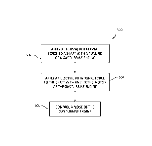
[0044] Referring to FIGS. 1 and 5, a method 500 reducing noise emitted by a
hybrid-electric gas
turbine engine for an aircraft is provided. FIG. 7 illustrates a flowchart of
the method 500. For
ease of description, the method 500 is described below with reference to the
gas turbine engine
10. The method 500, however, may alternatively be performed with other gas
turbine engines or
aircraft propulsion systems. The controller 58 may execute instructions stored
in memory 60,
thereby causing the controller 58 to execute one or more steps of the method
500. Unless
otherwise noted herein, it should be understood that the steps of method 500
are not required to
be performed in the specific sequence in which they are discussed below and,
in various
embodiments, the steps of method 500 may be performed separately or
simultaneously.
[0045] In Step 502, a thermal rotational force (e.g., a torque) is applied to
the propeller 12 by the
low-pressure power turbine 40. For example, the low-pressure power turbine 40
may drive the
propeller 12 by applying the first rotational force via the power turbine
shaft 42, the input shaft 50,
and/or the output shaft 48, as discussed above. The term "thermal rotational
force" is used herein
11
Date Recue/Date Received 2023-05-02
to refer to the rotational force applied by the thermal engine components of
the gas turbine engine
10, such as the low-pressure power turbine 40, to provide thrust for the
aircraft.
[0046] In Step 504, an electric rotational force (e.g., a torque) is applied
to the propeller 12 by the
electric motor 52. For example, the electric motor 52 may drive the propeller
12 by applying the
electric rotational force via the power turbine shaft 42, the input shaft 50,
and/or the output shaft
48, as discussed above. The electric rotational force applied by the electric
motor 52 may be in
combination with the thermal rotational force applied by the low-pressure
power turbine 40. The
electric rotational force applied by the electric motor 52 may, at times, be
the only rotational force
applied to the propeller 12 via the power turbine shaft 42, the input shaft
50, and/or the output
shaft 48. The term "electric rotational force" is used herein to refer to the
rotational force applied
by the electric motor 52 to provide thrust for the aircraft. The thermal
rotational force and the
electric rotational force may define a total rotational force which is applied
directly or indirectly via
the power turbine shaft 42, the input shaft 50, and/or the output shaft 48, as
discussed above.
The total rotational force may have a rotational force ratio which is a ratio
of the electric rotational
force to the thermal rotational force.
[0047] In Step 506, the noise emitted by the gas turbine engine 10 is
controlled. Controlling the
noise emitted by the gas turbine engine 10 may include controlling (e.g.,
regulating) the thermal
rotational force applied by the low-pressure power turbine 40, the electric
rotational force applied
by the electric motor 52, and/or the pitch of the plurality of propeller
blades 74. In particular, the
operational power of the gas turbine engine 10 may be reduced by reducing
thermal rotational
force applied by the low-pressure power turbine 40 relative to the electric
rotational force applied
by the electric motor 52. The operational power of the gas turbine engine 10
may be reduced
below the predetermined minimum operational power level for the current flight
condition the gas
turbine engine 10 and associated aircraft. In this case, the electric
rotational force applied by the
electric motor 52 may compensate for the reduction in the thermal rotational
force applied by the
low-pressure power turbine 40, thereby allowing the gas turbine engine 10 to
maintain sufficient
propulsive capability to support the current flight condition. In some
embodiments, the thermal
rotational force of the low-pressure power turbine 40 may be reduced while the
electric rotational
force applied by the electric motor 52 may be increased. For example, during a
takeoff flight
condition, a relatively high electric rotational force applied by the electric
motor 52 may allow the
gas turbine engine 10 to support an acceptable climb gradient while minimizing
operational power,
and thereby noise emitted from the gas turbine engine 10.
12
Date Recue/Date Received 2023-05-02
[0048] During a takeoff flight condition, the total rotational force may be
maintained constant or
substantially constant (i.e., maintained within a range of +1- five percent
(5%) of the total rotational
force) for all or a substantial portion of the takeoff flight condition. The
total rotational force may
have an initial rotational force ratio when the aircraft associated with the
gas turbine engine 10 is
on or proximate the ground. The initial rotational force ratio may be at least
1:1, electric rotational
force to thermal rotational force. An initial rotational force ratio of at
least 1:1 may correspond to
a fifty percent (50%) reduction in a noise output of the gas turbine engine 10
relative to a
conventional gas turbine engine (e.g., a gas turbine engine which does not use
an electric motor
to apply rotational force for propulsion). The initial rotational force ratio
may be between 1:1 and
2:1, electric rotational force to thermal rotational force. The initial
rotational force ratio may be at
least 2:1, electric rotational force to thermal rotational force. An initial
rotational force ratio of at
least 2:1 may correspond to a seventy-five percent (75%) reduction in a noise
output of the gas
turbine engine 10 relative to a conventional gas turbine engine. As an
altitude of the aircraft
increases during a takeoff flight condition, the noise emitted by the gas
turbine engine 10 may
become less impactful at the ground (e.g., as measured by noise sensors on the
ground). Step
506 may include reducing the rotational force ratio from the initial
rotational force ratio as an
altitude of the aircraft 1000 increases. Step 506 may further include
maintaining the total
rotational force substantially constant as the rotational force ratio is
reduced from the initial force
ratio. For example, the electric rotational force applied by the electric
motor 52 may be reduced
while the thermal rotational force applied by the low-pressure power turbine
40 is increased. The
rotational force ratio may be reduced from the initial rotational force ratio
to a final rotational force
ratio for the takeoff flight condition or for a stage of the takeoff flight
condition, where the final
rotational force ratio is less than the initial rotational force ratio.
[0049] In the case of an operational power cutback flight condition for a
takeoff, Step 506 may
include applying a first total rotational force during a first stage of the
takeoff flight condition and
a second total rotational force during a second stage of the takeoff flight
condition, where the first
total rotational force is different than the second total rotational force.
The first stage of the takeoff
flight condition may have a first average climb gradient which is greater than
a second average
climb gradient of the second stage of the takeoff flight condition. For
example, the first stage of
the takeoff flight condition may include points B, C, and D of the takeoff
profile 64 of FIG. 3 and
the second stage of the takeoff flight condition may include points D, E, and
F of the takeoff profile
64 of FIG. 3. The first total rotational force during the first stage may,
therefore, be greater than
the second total rotational force during the second stage. The first total
rotational force and the
13
Date Recue/Date Received 2023-05-02
second total rotational force may be maintained substantially constant during
the respective first
stage and second stage. In some embodiments, the first rotational force ratio
may include a final
rotational force ratio of the first stage, where the final rotational force
ratio is different than the
second rotational force ratio. For example, when initiating an operational
power cutback (e.g.,
point D of the takeoff profile 64), the electric rotational force applied by
the electric motor 52 may
be reduced to establish the second total rotational force for the second stage
of the takeoff flight
condition. Alternatively, when initiating the operational power cutback, the
thermal rotational force
applied by the low-pressure power turbine 40 may be reduced to establish the
second total
rotational force for the second stage of the takeoff flight condition.
Alternatively, when initiating
the operational power cutback, the electric rotational force applied by the
electric motor 52 and
the thermal rotational force applied by the low-pressure power turbine 40 may
be reduced to
establish the second total rotational force for the second stage of the
takeoff flight condition. In
some embodiments, the thermal rotational force applied by the low-pressure
power turbine 40
may be reduced in the second stage such that all or substantially all of the
propulsive capability
of the gas turbine engine 10 is provided by the electric motor 52.
[0050] In some other flight conditions, such as an approach condition, the
power turbine shaft 42
may be decoupled from the input shaft 50 (e.g., using the clutch 54) such that
the power turbine
shaft 42 does not apply a rotational force to the input shaft 50. The low-
pressure power turbine
40 may, therefore, be maintained in a "standby" condition in which the load on
the low-pressure
power turbine 40 is significantly reduced, but the low-pressure power turbine
40 continues to be
driven by combustion gases along the core flow path 24. Accordingly, in the
event that additional
propulsive capability is required (e.g., fora turnaround procedure), the low-
pressure power turbine
40 can be quickly re-coupled with the input shaft 50 to provide increased
propulsive capability.
[0051] In some embodiments, Step 506 may additionally or alternatively include
adjusting the
pitch of each propeller blade 74 for the plurality of propeller blades 74 to
reduce or further reduce
the noise emitted by the gas turbine engine 10. By adjusting the propeller
blade 74 pitch, the
rotation speed of the propeller 12 may be decreased while the thrust provided
by the propeller 12
may be maintained substantially constant (e.g., by increasing the propeller 12
torque).
[0052] It is noted that various connections are set forth between elements in
the preceding
description and in the drawings. It is noted that these connections are
general and, unless
specified otherwise, may be direct or indirect and that this specification is
not intended to be
limiting in this respect. A coupling between two or more entities may refer to
a direct connection
14
Date Recue/Date Received 2023-05-02
or an indirect connection. An indirect connection may incorporate one or more
intervening
entities. It is further noted that various method or process steps for
embodiments of the present
disclosure are described in the following description and drawings. The
description may present
the method and/or process steps as a particular sequence. However, to the
extent that the
method or process does not rely on the particular order of steps set forth
herein, the method or
process should not be limited to the particular sequence of steps described.
As one of ordinary
skill in the art would appreciate, other sequences of steps may be possible.
Therefore, the
particular order of the steps set forth in the description should not be
construed as a limitation.
[0053] Furthermore, no element, component, or method step in the present
disclosure is intended
to be dedicated to the public regardless of whether the element, component, or
method step is
explicitly recited in the claims. No claim element herein is to be construed
under the provisions
of 35 U.S.C. 112(f) unless the element is expressly recited using the phrase
"means for." As used
herein, the terms "comprises", "comprising", or any other variation thereof,
are intended to cover
a non-exclusive inclusion, such that a process, method, article, or apparatus
that comprises a list
of elements does not include only those elements but may include other
elements not expressly
listed or inherent to such process, method, article, or apparatus.
[0054] While various aspects of the present disclosure have been disclosed, it
will be apparent
to those of ordinary skill in the art that many more embodiments and
implementations are possible
within the scope of the present disclosure. For example, the present
disclosure as described
herein includes several aspects and embodiments that include particular
features. Although these
particular features may be described individually, it is within the scope of
the present disclosure
that some or all of these features may be combined with any one of the aspects
and remain within
the scope of the present disclosure. References to "various embodiments," "one
embodiment,"
"an embodiment," "an example embodiment," etc., indicate that the embodiment
described may
include a particular feature, structure, or characteristic, but every
embodiment may not
necessarily include the particular feature, structure, or characteristic.
Moreover, such phrases
are not necessarily referring to the same embodiment. Further, when a
particular feature,
structure, or characteristic is described in connection with an embodiment, it
is submitted that it
is within the knowledge of one skilled in the art to effect such feature,
structure, or characteristic
in connection with other embodiments whether or not explicitly described.
Accordingly, the
present disclosure is not to be restricted except in light of the attached
claims and their
equivalents.
Date Recue/Date Received 2023-05-02