Language selection

Search

Patent 3199716 Summary

Third-party information liability

Some of the information on this Web page has been provided by external sources. The Government of Canada is not responsible for the accuracy, reliability or currency of the information supplied by external sources. Users wishing to rely upon this information should consult directly with the source of the information. Content provided by external sources is not subject to official languages, privacy and accessibility requirements.

Claims and Abstract availability

Any discrepancies in the text and image of the Claims and Abstract are due to differing posting times. Text of the Claims and Abstract are posted:

  • At the time the application is open to public inspection;
  • At the time of issue of the patent (grant).
(12) Patent: (11) CA 3199716
(54) English Title: LIQUID OUTLET DEVICE FOR REAGENT KIT
(54) French Title: DISPOSITIF DE SORTIE DE LIQUIDE POUR KIT DE REACTIFS
Status: Granted and Issued
Bibliographic Data
(51) International Patent Classification (IPC):
  • B05B 01/00 (2006.01)
  • B05B 01/30 (2006.01)
  • F16K 01/00 (2006.01)
  • F16K 11/065 (2006.01)
(72) Inventors :
  • HAO, SHUSHUN (China)
  • SUI, YANJUN (China)
  • LIU, YI (China)
  • CHEN, LIZHU (China)
  • YAO, ZHAOHUI (China)
(73) Owners :
  • SHIJIAZHUANG HIPRO BIOTECHNOLOGY CO., LTD.
(71) Applicants :
  • SHIJIAZHUANG HIPRO BIOTECHNOLOGY CO., LTD. (China)
(74) Agent: GOWLING WLG (CANADA) LLP
(74) Associate agent:
(45) Issued: 2023-12-12
(86) PCT Filing Date: 2021-09-10
(87) Open to Public Inspection: 2022-05-27
Examination requested: 2023-06-09
Availability of licence: N/A
Dedicated to the Public: N/A
(25) Language of filing: English

Patent Cooperation Treaty (PCT): Yes
(86) PCT Filing Number: PCT/CN2021/117667
(87) International Publication Number: CN2021117667
(85) National Entry: 2023-05-19

(30) Application Priority Data:
Application No. Country/Territory Date
202011317359.3 (China) 2020-11-23

Abstracts

English Abstract


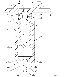
A liquid outlet device for reagent kit includes a spray pipe and a nozzle that
is arranged at one end of
the spray pipe; where the spray pipe includes a spray pipe body (1-1), a spray
hole (1-2) extending
along the axial direction of the spray pipe body (1-1) and a magnet bar (1-3)
arranged in the spray
hole (1-2). A plurality of blocking strips (1-4) are uniformly arranged on the
inner wall of the spray
hole (1-2), where each blocking strip (1-4) extends along the axial direction
of the spray hole (1-2);
one end of each blocking strip (1-4) is provided with a shoulder (1-5) that
extends towards the center
of the spray hole (1-2); the magnet bar (1-3) is able to move along the axial
direction of the spray
hole (1-2) in a space defined by a plurality of shoulders (1-5) and the
plurality of blocking strips
(1-4); the nozzle includes an annular sleeve (2-1), an end plate (2-2)
provided at one end of the
annular sleeve (2-1), a nozzle pipe (2-3) provided at the center of the end
plate (2-2) and a conical
nozzle opening (2-4) formed at an end of the nozzle pipe (2-3); an annular
blocking flange (2-5)
surrounding the nozzle pipe (2-3) is further provided on the end plate (2-2)
and an annular groove
(2-7) is formed between the nozzle pipe (2-3) and the annular blocking flange
(2-5); a liquid channel
(2-6) communicated with the interior of the annular sleeve (2-1) is formed in
the nozzle pipe (2-3)
and the conical nozzle opening (2-4); and the annular sleeve (2-1) and the
spray pipe body (1-1) are
connected through threaded connection or clamped connection. The structure of
the liquid outlet
device provided by the present application is simple; it has good liquid
outlet effect, is convenient to
replace the nozzle, and is conducive to achieving miniaturization.


French Abstract

Dispositif de sortie de liquide pour un kit de réactifs comprenant un tuyau de pulvérisation et une buse disposée au niveau de la partie d'extrémité du tuyau de pulvérisation. Le tuyau de pulvérisation comprend un corps de tuyau de pulvérisation (1-1), un trou de pulvérisation (1-2) formé dans la direction axiale du corps de tuyau de pulvérisation (1-1) et une barre magnétique (1-3) disposée dans le trou de pulvérisation (1-2); une pluralité de bandes de blocage (1-4) dans la direction axiale du trou de pulvérisation (1-2) est formée uniformément sur la paroi interne du trou de pulvérisation (1-2); une extrémité de chaque bande de blocage (1-4) est dotée d'un épaulement (1-5) qui s'étend en direction du centre du trou de pulvérisation (1-2); la barre magnétique (1-3) se déplace le long de la direction axiale du trou de pulvérisation (1-2) dans un espace défini par l'épaulement (1-5) et les bandes de blocage (1-4); la buse comprend un manchon annulaire (2-1), une plaque d'extrémité (2-2) disposée au niveau d'une extrémité du manchon annulaire (2-1), un tuyau de buse (2-3) disposé au niveau du centre de la plaque d'extrémité (2-2) et une ouverture de buse conique (2-4) formée au niveau de la partie d'extrémité du tuyau de buse (2-3); un bord de blocage annulaire (2-5) entourant la périphérie du tuyau de buse (2-3) est en outre disposé sur la plaque d'extrémité (2-2); un canal de liquide (2-6) communiquant avec l'intérieur du manchon annulaire (2-1) est formé dans le tuyau de buse (2-3) et l'ouverture de buse conique (2-4); une rainure annulaire (2-7) est définie entre le tuyau de buse (2-3) et le bord de blocage annulaire (2-5); et le manchon annulaire (2-1) est en liaison filetée ou en liaison serrée avec le corps de tuyau de pulvérisation (1-1). Le dispositif de sortie de liquide pour le kit de réactifs présente une structure simple, un bon effet de pulvérisation de liquide, est pratique en termes de remplacement de buse et est utile pour réaliser la miniaturisation du dispositif.

Claims

Note: Claims are shown in the official language in which they were submitted.


IN THE CLMMS:
1. A liquid outlet device for a reagent kit, comprising a spray pipe and a
nozzle that is
arranged at one end of the spray pipe; wherein:
thc spray pipe comprises a spray pipe body, a spray hole extending along an
axial
direction of the spray pipe body and a magnet bar arranged in the spray hole;
a plurality of
blocking strips are uniformly arranged on an inner wall of the spray hole,
wherein each blocking
strip extends along an axial direction of the spray hole; one end of each
blocking strip is
provided with a shoulder that extends towards a center of the spray hole; the
magnet bar is
movable along the axial direction of the spray hole in a space defined by a
plurality of shoulders
and the plurality of blocking strips;
the nozzle comprises an annular sleeve, an end plate provided at one end of
the annular
sleeve, a nozzle pipe provided at a center of the end plate and a conical
nozzle opening formed at
an end of the nozzle pipe; an annular blocking flange surrounding the nozzle
pipe is further
provided on the end plate and an annular groove is formed between the nozzle
pipe and the
annular blocking flange; a liquid channel communicable with an interior of the
annular sleeve is
formed in the nozzle pipe and the conical nozzle opening; and
the annular sleeve and the spray pipe body are connected through threaded
connection
or clamped connection.
2. The liquid outlet device for a reagent kit according to claim 1, wherein
one end of the
spray pipe body is located close to the plurality of shoulders, an outer side
wall of the end of the
spray pipe body is provided with an external thread, and the other end of the
annular sleeve is
an open end and is provided with an internal thread matching the external
thread.
3. The liquid outlet device for a reagent kit according to claim 1, wherein
one end of the
spray pipe body that is located away from the plurality of shoulders is
provided with an annular
-8-
CA 03199716 2023- 5- 19

connecting part, an outer side wall of the annular connecting part is provided
with an annular
convex, and the other end of the annular sleeve is an open end and is provided
with an annular
concave matching the annular convex.
4. The liquid outlet device for a reagent kit according to any one of
claims 1 to 3, wherein a
sealing gasket is arranged in the annular sleeve.
5. The liquid outlet device for a reagent kit according to claim 1, wherein
the magnet bar is
cylinder shaped.
6. The liquid outlet device for a reagent kit according to claim J.,
wherein a number of the
plurality of blocking strips is three or more than three.
7. The liquid outlet device for a reagent kit according to claim 6, wherein
a diameter of a
cylinder space formed by the plurality of shoulders is less than a section
diameter of the magnet
bar, and a diameter of a cylinder space formed by the plurality of blocking
strips is greater than
the section diameter of the magnet bar.
-9-
CA 03199716 2023- 5- 19

Description

Note: Descriptions are shown in the official language in which they were submitted.


LIQUID OUTLET DEVICE FOR REAGENT KIT
TECHNICAL FIELD
[00011 The application belongs to the technical field of liquid
outlet structure, and
particularly relates to a liquid outlet device for reagent kit.
BACKGROUND
[0002] Reagent kits are common laboratory supplies used to
preserve reaction reagents. In
the prior art, in a laboratory, pipettes or syringes are required to draw the
reagents out the kits
before injecting the reagents into an experimental instrument. When drawing
different reagents,
it is required to replace the pipette tip or clean the syringe and the needle
of the syringe, which is
cumbersome and time-consuming. And, the amount of reagent drawn out is easily
affected by
the operator's operation method, which is not conducive to conversion to
automated
instruments for operation.
TECHNICAL PROBLEMS
[00031 The application provides a liquid outlet device for reagent
kit. Its structure is simple
and compact. It can take liquid accurately and realize automation easily.
TECHNICAL SOLUTIONS
[00041 The technical solutions adopted by the present application
are as follows:
[00051 a liquid outlet device for reagent kit includes a spray
pipe and a nozzle that is
arranged at one end of the spray pipe;
[0006] the spray pipe includes a spray pipe body, a spray hole
extending along an axial
direction of the spray pipe body and a magnet bar arranged in the spray hole;
a plurality of
blocking strips are uniformly arranged on an inner wall of the spray hole,
where each blocking
strip extends along an axial direction of the spray hole; one end of each
blocking strip is
-1 -
CA 03199716 2023- 5- 19

provided with a shoulder that extends towards a center of the spray hole; the
magnet bar is able
to move along the axial direction of the spray hole in a space defined by a
plurality of shoulders
and the plurality of blocking strips;
[00071 the nozzle includes an annular sleeve, an end plate
provided at one end of the
annular sleeve, a nozzle pipe provided at a center of the end plate and a
conical nozzle opening
formed at an end of the nozzle pipe; an annular blocking flange surrounding
the nozzle pipe is
further provided on the end plate and an annular groove is formed between the
nozzle pipe and
the annular blocking flange; a liquid channel communicated with an interior of
the annular
sleeve is formed in the nozzle pipe and the conical nozzle opening;
[00081 the annular sleeve and the spray pipe body are connected
through threaded
connection or clamped connection.
[00091 In a possible implement, one end of the spray pipe body is
located close to the
plurality of shoulders and an outer side wall of the end of the spray pipe
body is provided with
an external thread, and the other end of the annular sleeve is an open end and
is provided with
an internal thread matching the external thread.
[00101 In a possible implement, one end of the spray pipe body
that is located far away
from the plurality of shoulders is provided with an annular connecting part,
an outer side wall of
the annular connecting part is provided with an annular convex, and the other
end of the
annular sleeve is an open end and is provided with an annular concave matching
the annular
convex.
[00111 In a possible implement, a sealing gasket is arranged in
the annular sleeve.
[00121 In a possible implement, the magnet bar is cylinder shaped.
[00131 In a possible implement, the number of the plurality of
blocking strips is three or
more than three.
-2-
CA 03199716 2023- 5- 19

[0014] In a possible implement, a diameter of a cylinder space
enclosed by the plurality of
shoulders is less than a section diameter of the magnet bar, and a diameter of
a cylinder space
enclosed by the plurality of blocking strips is greater than the section
diameter of the magnet
bar.
ADVANTAGEOUS EFFECTS OF THE DISCLOSURE
[0015] The advantageous effects of the liquid outlet device for
reagent kit provided by the
present application are as follows: the spray pipe and the nozzle are
connected through threaded
connection or clamped connection, which facilitates disassembly and
replacement.
[0016] The shoulders in the spray hole of the spray pipe body are
used to prevent the
magnet bar from blocking the liquid inlet end of the spray pipe. A gap is
formed between two
adjacent blocking strips for liquid flow. Liquid can flow in the gaps and will
not be blocked by
the magnet bar. When the magnet bar moves towards the nozzle to the other end
of the spray
pipe, the magnet bar can block the nozzle connected on the spray pipe. The
reciprocating
movement of the magnet bar in the spray hole realizes the opening and closing
of the spray pipe.
[0017] The outer side wall of the conical nozzle opening of the
nozzle is designed as a
conical structure, which can prevent droplet from adhering to the lower end of
the nozzle. The
nozzle pipe is surrounded by the annular blocking flange and the annular
groove, which can
prevent the slender nozzle pipe from being damaged by external forces. When
installing a
container for receiving liquid reagent flowing out the nozzle, the side walls
to the annular groove
can clamp the sealing cover of the container to prevent the sealing cover from
being disengaged.
The liquid outlet device provided by the present application is easy to
install and has good liquid
outlet effect.
[0018] The structure of the liquid outlet device provided by the
present application is
ingenious and simple, and it is conducive to achieving automation and
miniaturization.
-3-
CA 03199716 2023- 5- 19

BRIEF DESCRIPTION OF THE DRAWINGS
[0019] Fig. 1 is a schematic sectional view of the liquid outlet
device for reagent kit
according to an embodiment 1; and
[0020] Fig. 2 is a schematic sectional view of the liquid outlet
device for reagent kit
according to an embodiment 2.
DETAILED DESCRIPTION OF ILLUSTRATIVE EMBODIMENTS
[0021] In the following, referencing to the drawings, the
technical solutions of the
embodiments of the present application are described clearly and completely.
[0022] Embodiment 1
[0023] As shown in Fig. 1, the liquid outlet device for reagent
kit includes a spray pipe and a
nozzle that is arranged at one end of the spray pipe.
[0024] The spray pipe includes a spray pipe body 1-1, a spray hole
1-2 extending along the
axial direction of the spray pipe body 1-1 and a magnet bar 1-3 arranged in
the spray hole 1-2. A
plurality of blocking strips 1-4 are uniformly arranged on the inner wall of
the spray hole 1-2,
where each blocking strip 1-4 extends along the axial direction of the spray
hole 1-2. One end of
each blocking strip 1-4 is provided with a shoulder 1-5 that extends towards
the center of the
spray hole 1-2. The magnet bar 1-3 is able to move along the axial direction
of the spray hole 1-2
in a space defined by a plurality of shoulders 1-5 and the plurality of
blocking strips 1-4.
[0025] The spray pipe body 1-1 is fixed to reagent kit 3. The
spray hole 1-2 in the spray pipe
body 1-1 is communicated with the liquid outlet hole 4 of the reagent kit 3.
The end of the spray
pipe body 1-1 close to the shoulders is a liquid inlet end and the liquid
reagent in the reagent kit
can flow into the spray hole 1-2 of the spray pipe body 1-1 through this
liquid inlet end.
[0026] The diameter of a cylinder space formed by all the
shoulders 1-5 is less than the
section diameter of the magnet bar 1-3, and the diameter of a cylinder space
formed by all the
-4-
CA 03199716 2023- 5- 19

blocking strips 1-4 is greater than the section diameter of the magnet bar 1-
3. Therefore, the
magnet bar 1-3 is able to reciprocate in the cylinder space formed by all the
blocking strips 1-4,
but when it moves towards the liquid outlet hole 4 of the reagent kit 3 and
contacts the
shoulders 1-5, it is blocked by the shoulders 1-5 and cannot continue to move
to prevent from
blocking the liquid outlet hole 4. A gap is formed between two adjacent
blocking strips 1-4 and
liquid can flow in the spray hole 1-2 through the gaps without being blocked
by the magnet bar
1-3.
[00271 The nozzle includes an annular sleeve 2-1, an end plate 2-2
provided at one end of
the annular sleeve 2-1, a nozzle pipe 2-3 provided at the center of the end
plate 2-2 and a
conical nozzle opening 2-4 formed at an end of the nozzle pipe 2-3. An annular
blocking flange
2-5 surrounding the nozzle pipe 2-3 is further provided on the end plate 2-2
and an annular
groove 2-7 is formed between the nozzle pipe 2-3 and the annular blocking
flange 2-5. A liquid
channel 2-6 communicated with the interior of the annular sleeve 2-1 is formed
in the nozzle
pipe 2-3 and the conical nozzle opening 2-4.
[0028] The outer side wall of the conical nozzle opening 2-4 of
the nozzle is designed as a
conical structure, which can prevent droplet from adhering to the lower end of
the nozzle and
forming a hanged-droplet. The nozzle pipe 2-3 is conical frustum shaped or
cylindrical. The
nozzle pipe 2-3 is surrounded by the annular blocking flange 2-5 and the
annular groove 2-7,
which can prevent the slender nozzle pipe 2-3 from being damaged by external
forces. When
installing a container for receiving liquid reagent flowing out the nozzle,
the annular groove 2-7
can clamp the sealing cover of the container to prevent the sealing cover from
being disengaged.
[0029] The annular sleeve 2-1 and the spray pipe body 1-1 arc
connected through threaded
connection. Specifically, the end of the spray pipe body 1-1 located close to
the shoulders 1-5 is
provided with an external thread 1-6, that is, the outer side wall of this end
of the spray pipe
-5-
CA 03199716 2023- 5- 19

body 1-1 is provided with an external thread 1-6. The open end of the annular
sleeve 2-1 is
provided with an internal thread 2-8 matching the external thread 1-6.
[0030] There are no shoulders at the end of the spray pipe body 1-
1 which is inserted into
the annular sleeve 2-1. Therefore, the magnet bar can contact the liquid
channel in the nozzle
pipe 2-3 to prevent liquid from entering the nozzle, thus achieve the purpose
of sealing and
blocking.
[0031] A sealing gasket 2-10 is arranged in the annular sleeve 2-
1. The center of the sealing
gasket 2-10 is provided with a through hole 2-11. The diameter of the end of
the through hole 2-
11 close to the spray hole 1-2 is less than the diameter of the end close to
the liquid channel 2-6,
which is benefit for sealing and blocking the end close to the spray hole 1-2.
The sealing gasket
2-10 can seal the gaps between the spray pipe body 1-1 and annular sleeve 2-1
to prevent liquid
leaking. The magnet bar 1-3 is cylindrical. The number of the blocking strips
1-4 is three or
more than three and the blocking strips 1-4 uniformly distributed on the inner
wall of the spray
hole 1-2. The spray pipe shown in Fig. 1 has six blocking strips 1-4. Too few
blocking strips (one
or two) cannot restraint the magnet bar sufficiently causing that the magnet
bar cannot
maintain the correct posture during movement thus contacting to the inner wall
of the nozzle,
and too many blocking strips will make the gap between two adjacent blocking
strips too
narrow, both of which will cause the flow resistance of liquid reagent to
increase.
[0032] To drive the magnet bar reciprocating in the spray hole 1-
2, an electromagnet may
be sleeved at the liquid inlet end of the spray pipe body 1-1 and a permanent
magnet ring may
be sleeved at the annular connecting part 1-7 of the spray pipe body
The polarity of the end
of the magnet bar close to the permanent magnet ring and the polarity of the
end of the
permanent magnet ring close to the magnet bar are opposite. Therefore, the
permanent magnet
ring can attract the magnet bar to seal and block the nozzle, thus stopping
the liquid from
flowing out. When it is time to let the liquid flow out, energize the
electromagnet. The magnetic
-6-
CA 03199716 2023- 5- 19

force of the electromagnet is greater than that of the permanent magnet ring.
Therefore, the
magnet bar can be attracted to the liquid inlet end of the spray pipe and
contacts the shoulders,
and the liquid reagent can flow into the nozzle through the gaps between the
blocking strips 1-4
and flow out finally.
[00331 Embodiment 2
[00341 The liquid outlet device provided by the embodiment 2 is
the same as that provided
by the embodiment 1 expect that, in the embodiment 2, as shown in Fig. 2, the
annular sleeve 2-
1 and the spray pipe body 1-1 are connected through clamped connection.
Specifically, the end
of the spray pipe body 1-1 that is located far away from the shoulders 1-5 is
provided with an
annular connecting part 1-7. The outer side wall of the annular connecting
part 1-7 is provided
with an annular convex 1-8, and the open end of the annular sleeve 2-1 is
provided with an
annular concave 2-9 matching the annular convex
The annular concave 2-9 is coordinated
with the annular convex 1-8 on the spray pipe body 1-1. The installation can
be achieved by
inserting the annular connecting part 1-7 into the annular sleeve 2-1 which is
convenient and
fast, and the installation is secure and will not accidentally disengage. The
liquid reagent can
flow through the liquid outlet of the reagent kit and the spray pipe, then
flow out from the liquid
channel in the nozzle.
[00351 The above descriptions are only preferred embodiments of
the present disclosure,
and are not intended to limit the present disclosure. Any modifications,
equivalent replacements
and improvements made within the spirit and principle of the present
disclosure shall be
included within the protection scope of the present disclosure.
-7-
CA 03199716 2023- 5- 19

Representative Drawing
A single figure which represents the drawing illustrating the invention.
Administrative Status

2024-08-01:As part of the Next Generation Patents (NGP) transition, the Canadian Patents Database (CPD) now contains a more detailed Event History, which replicates the Event Log of our new back-office solution.

Please note that "Inactive:" events refers to events no longer in use in our new back-office solution.

For a clearer understanding of the status of the application/patent presented on this page, the site Disclaimer , as well as the definitions for Patent , Event History , Maintenance Fee  and Payment History  should be consulted.

Event History

Description Date
Maintenance Request Received 2024-08-30
Maintenance Fee Payment Determined Compliant 2024-08-30
Inactive: Grant downloaded 2023-12-13
Letter Sent 2023-12-12
Grant by Issuance 2023-12-12
Inactive: Cover page published 2023-12-11
Inactive: Final fee received 2023-10-19
Pre-grant 2023-10-19
Letter Sent 2023-09-14
Notice of Allowance is Issued 2023-09-14
Inactive: QS passed 2023-09-12
Inactive: Approved for allowance (AFA) 2023-09-12
Inactive: Cover page published 2023-07-04
Letter Sent 2023-06-30
Request for Examination Requirements Determined Compliant 2023-06-09
All Requirements for Examination Determined Compliant 2023-06-09
Request for Examination Received 2023-06-09
Advanced Examination Requested - PPH 2023-06-09
Advanced Examination Determined Compliant - PPH 2023-06-09
Inactive: IPC assigned 2023-06-06
Inactive: First IPC assigned 2023-06-06
Inactive: IPC assigned 2023-06-06
Application Received - PCT 2023-05-19
Request for Priority Received 2023-05-19
Priority Claim Requirements Determined Compliant 2023-05-19
Amendment Received - Voluntary Amendment 2023-05-19
Letter sent 2023-05-19
Amendment Received - Voluntary Amendment 2023-05-19
National Entry Requirements Determined Compliant 2023-05-19
Application Published (Open to Public Inspection) 2022-05-27

Abandonment History

There is no abandonment history.

Maintenance Fee

The last payment was received on 2023-08-11

Note : If the full payment has not been received on or before the date indicated, a further fee may be required which may be one of the following

  • the reinstatement fee;
  • the late payment fee; or
  • additional fee to reverse deemed expiry.

Patent fees are adjusted on the 1st of January every year. The amounts above are the current amounts if received by December 31 of the current year.
Please refer to the CIPO Patent Fees web page to see all current fee amounts.

Fee History

Fee Type Anniversary Year Due Date Paid Date
Basic national fee - standard 2023-05-19
Request for examination - standard 2025-09-10 2023-06-09
MF (application, 2nd anniv.) - standard 02 2023-09-11 2023-08-11
Final fee - standard 2023-10-19
MF (patent, 3rd anniv.) - standard 2024-09-10 2024-08-30
Owners on Record

Note: Records showing the ownership history in alphabetical order.

Current Owners on Record
SHIJIAZHUANG HIPRO BIOTECHNOLOGY CO., LTD.
Past Owners on Record
LIZHU CHEN
SHUSHUN HAO
YANJUN SUI
YI LIU
ZHAOHUI YAO
Past Owners that do not appear in the "Owners on Record" listing will appear in other documentation within the application.
Documents

To view selected files, please enter reCAPTCHA code :


To view images, click a link in the Document Description column (Temporarily unavailable). To download the documents, select one or more checkboxes in the first column and then click the "Download Selected in PDF format (Zip Archive)" or the "Download Selected as Single PDF" button.

List of published and non-published patent-specific documents on the CPD .

If you have any difficulty accessing content, you can call the Client Service Centre at 1-866-997-1936 or send them an e-mail at CIPO Client Service Centre.

({010=All Documents, 020=As Filed, 030=As Open to Public Inspection, 040=At Issuance, 050=Examination, 060=Incoming Correspondence, 070=Miscellaneous, 080=Outgoing Correspondence, 090=Payment})


Document
Description 
Date
(yyyy-mm-dd) 
Number of pages   Size of Image (KB) 
Description 2023-05-19 7 277
Claims 2023-05-19 2 60
Drawings 2023-05-19 2 46
Representative drawing 2023-07-03 1 14
Abstract 2023-06-12 1 36
Representative drawing 2023-06-12 1 37
Abstract 2023-05-18 1 36
Description 2023-05-18 7 278
Claims 2023-05-18 2 66
Drawings 2023-05-18 2 49
Confirmation of electronic submission 2024-08-29 1 61
Courtesy - Acknowledgement of Request for Examination 2023-06-29 1 422
Commissioner's Notice - Application Found Allowable 2023-09-13 1 578
PPH request 2023-06-08 7 340
PPH supporting documents 2023-06-08 14 754
Final fee 2023-10-18 4 112
Electronic Grant Certificate 2023-12-11 1 2,527
Voluntary amendment 2023-05-18 13 417
National entry request 2023-05-18 1 29
Declaration of entitlement 2023-05-18 1 17
Patent cooperation treaty (PCT) 2023-05-18 2 117
International search report 2023-05-18 4 144
Patent cooperation treaty (PCT) 2023-05-18 1 44
Patent cooperation treaty (PCT) 2023-05-18 1 65
National entry request 2023-05-18 11 255
Patent cooperation treaty (PCT) 2023-05-18 2 57
Courtesy - Letter Acknowledging PCT National Phase Entry 2023-05-18 2 49
Patent cooperation treaty (PCT) 2023-05-18 1 42