Note: Descriptions are shown in the official language in which they were submitted.
WO 2022/133379
PCT/US2021/072509
MOUNT FOR AN OPTICAL STRUCTURE AND METHOD OF MOUNTING THE
OPTICAL STRUCTURE TO THE MOUNT
CROSS-REFERENCE TO PRIOR APPLICATION
This application claims priority to and the benefit thereof from United States
Patent Application
No. 17/122,418, filed December 15, 2020, titled "MOUNT FOR AN OPTICAL
STRUCTURE
AND METHOD OF MOUNTING THE OPTICAL STRUCTURE TO THE MOUNT," the
entirety of which is hereby incorporated herein by reference.
BACKGROUND
[0001] This disclosure relates to the field of mounts for high accuracy
optical structures,
including but not limited to, the following optical structures: reflective
panels; hollow
retroreflectors; roof mirrors; lateral transfer retroreflectors; and
periscopes (hereinafter
collectively referred to as "optical structures"). These optical structures
are old in the art.
[0002] When these optical structures are made or assembled for high accuracy
and precision it is
important to maintain the mutual perpendicularity and/or parallel orientations
of the reflective
surfaces and sometimes essential to ensure that the optical structure as a
whole does not move.
Hereinafter, when discussing either the perpendicular or parallel orientations
of the reflective
surfaces of the optical structures, this specification will refer to the
"orientations" of these
elements.
[0003] The orientations of the reflective surfaces are affected by external
stresses. With regard
to high accuracy and precise reflective panels, such as mirror panels to be
used for high accuracy
purposes in such optical structures, it is also important to try and maintain
as optically flat as
possible the reflective surfaces of the panels. External stresses cause
distortion of the optical
flatness of the reflective surfaces of the reflective panels of the optical
structures and these
distortions can then cause distortion to the exiting wayefront of the exiting
light ray. Such
distortion of the exiting light ray increases beam deviation, thereby causing
the exiting light ray
to no longer be parallel to the entering (incident) light ray.
-1 -
CA 03201719 2023- 6-8
WO 2022/133379
PCT/US2021/072509
SUMMARY
[0004] It would be desirable to assemble together the elements of an optical
structure in such a
manner as to eliminate or reduce the external stresses. It would also be
desirable that the manner
of mounting an optical structure to a mount does not add to these stresses,
but nevertheless,
securely retains the optical structure on the mount. As such, prior art mounts
for such optical
structures have usually been what is know in the art as "hard mount"
structures. A hard mount
structure is one that maintains the dimensional stability ("DS") of the
optical structure so that the
external stresses acting on the optical structure do not change the dimensions
of that optical
structure and therefore do not effect the optical flatness of the optical
structure' s reflective
surfaces.
[0005] The present mount also achieves secure mounting of the optical
structure in a manner
designed to help eliminate deflective stresses on the reflective surface(s) of
the optical structure
caused by the mounting of the optical structure to its mount. One or more
aspects of the present
mount thereby achieves DS, such that a hard mount construction is achieved. In
particular, for
the measurement of the DS of an optical structure and its mounting to another
structure, it is
important to maintain as near to perfect as possible the Optical Path
Difference (-OPD") between
the incident and reflected light rays entering and exiting the optical
structure. To accomplish this
in a hard mount configuration like that of the subject disclosure, it is
important that the
dimensional relationship between the reflective surfaces of the optical
structure that is attached
to another structure via the mounting assembly and the apex of the optical
structure be
maintained in all environmental conditions and changes in those environmental
conditions.
[0006] Examples of external stresses that can affect the optical flatness of a
reflective panel,
and/or the orientations of reflective surfaces of reflective panels of the
optical structures, are
thermal expansion or contraction of the substrate material from which the
panels are made,
deflection caused the bonding materials used to join elements together and/or
deflection caused
by curing of adhesives between, or tightening together of, the reflective
panel(s) and the item to
which it is mounted, the mass of the panels themselves, as well as vibration
of and/or shocks to
the combined mount and optical structure
-2-
CA 03201719 2023- 6-8
WO 2022/133379
PCT/US2021/072509
[0007] Accordingly, it would be desirable not only to assemble together the
elements of an
optical structure in such a manner as to reduce these stresses, but it is
equally important that the
mounting system/structure used to mount the optical structure to another
structure not add any
significant distortional forces to the optical structure. It would also be
desirable that the manner
of mounting an optical structure to its mount not add to these stresses, but
nevertheless, securely
retain the optical structure on the mount.
[0008] It is further desirable that the manner of mounting the optical
structure to the mount
(hereinafter referred to as "the combined structure") allows the optical
structure to move with,
and be in sync with, any movement of the mount when the combined structure
experiences
either, or both of, vibrational or shock forces.
[0009] Accordingly, it is an object of the invention to provide an improved
mount for an optical
structure.
[0010] Another object of the invention is to provide an improved mount for an
optical structure
which causes minimal external stresses to the reflective surfaces of the
optical structure.
[0011] Still another object of the invention is to provide an improved mount
for an optical
structure wherein the mount achieves reductions in movement of the optical
structure in order to
achieve higher-accuracy distance measurements.
[0012] An even further object of the invention is that the manner of mounting
the optical
structure to a mount allows the optical structure to move with, and be in sync
with, any
movement of the mount when the combined structure experiences either, or both
of, vibrational
or shock forces.
[0013] Yet a further object of the invention is to provide an improved mount
for an optical
structure wherein the mounting of the mount and optical structure to a support
structure is easy
and secure and adds no distortion to the wavefronts of the optical structure.
-3 -
CA 03201719 2023- 6-8
WO 2022/133379
PCT/US2021/072509
[0014] It is even a further object of the invention to provide an improved
method of mounting an
optical structure using the improved mount.
[0015] Other objects of the invention will in part be obvious and will in part
be apparent from
the following description.
BRIEF DESCRIPTION OF THE DRAWINGS
[0016] For the purposes of illustrating the various aspects of the invention,
wherein like
numerals indicate like elements, there are shown in the drawings simplified
forms that may be
employed, it being understood, however, that the invention is not limited by
or to the precise
arrangements and instrumentalities shown. To assist those of ordinary skill in
the relevant art in
making and using the subject matter hereof, reference is made to the appended
drawings and
figures, wherein:
[0017] FIG. 1 is a perspective view of a prior art assembly;
[0018] FIG. 2 is a front side elevational view of the prior art assembly of
FIG. 1;
[0019] FIG. 3 is a perspective view of an embodiment of the subject invention;
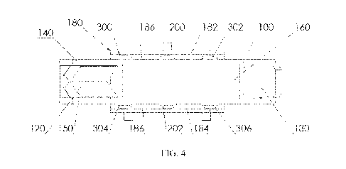
[0020] FIG. 4 is a front side elevational view of the embodiment of FIG. 3;
[0021] FIG. 5 is a top plan view of the embodiment of FIG. 3;
[0022] FIG. 6 is a cross-sectional view taken along line A-A of FIG. 5;
[0023] FIG. 7 a top plan view of an embodiment of the mounting pads of the
embodiment of
FIG. 3;
[0024] FIG. 8 is a side elevational view of the mounting pads of FIG. 7;
-4-
CA 03201719 2023- 6-8
WO 2022/133379
PCT/US2021/072509
[0025] FIG. 9 is a cross-sectional view of an embodiment of one of mounting
pads 200, 202 of
FIG. 4, taken along line B-B of FIG. 7; and
[0026] FIG. 10 is a cross-sectional view of an embodiment of one of mounting
pads 300, 302,
304, 306 or FIG. 4, taken along line B-B of FIG. 7.
DETAILED DESCRIPTION OF THE PREFERRED EMBODIMENTS
[0027] In accordance with the subject invention, an improved mount for, and
method of
mounting, an optical structure is provided. For ease and uniformity, the
optical structure used in
all of the figures is a lateral transfer retroflector ("LTR") 10 (FIGs. 1-2
(prior art)) and 1100
(FIGs. 3-6). Each LTR has a roof mirror (20, 120) and a mirror panel (30,
130). Each LTR
structure is formed using known in the art methods for forming the roof
mirrors and then
mounting a roof mirror and a mirror panel between upper (40, 140) and lower
(50, 150) support
members. Each LTR may also have a front support member (60, 160) and a back
support
member 162 (not shown in FEGs. 1 or 2) to assist with the stability of the
overall optical
structure joined between the upper and lower support members, as well as a
back support
member (not shown).
[0028] In the prior art assembly shown in FIGs. 1-2, a mount 70 is shown
attached to optical
structure 10 on the outside surfaces of upper and lower support members 40 and
50 of optical
structure 10. The attachment of mount 70 is achieved, in the prior art,
through use of four
mounting pads 80. Mounting pads 80 are, as previously described herein, all
hard mount
structures. To achieve this hard mount connection, mounting pads 80 are what
is known in the
art as being stiff. When the pads are made of polymeric materials, the
hardness is measured
using the Durometer scale. The Durometer scale measures hardness in terms of
the elasticity
(stiffness) of the material. As such, as used throughout this disclosure,
stiffness is meant to mean
the elasticity of the material as measured using the Durometer scale. For pads
formed of
polymeric material durometer values are broadly in the following ranges Shore
00:10-80 (for
softer) and Shore A:20-90 (for hard), but in most cases the achieved goals of
this disclosure will
be achieved in the ranges Shore A 40-90 (for hard) and Shore A 25-60 (for
softer).
-5-
CA 03201719 2023- 6-8
WO 2022/133379
PCT/US2021/072509
[0029] Turning now to the mounting of the subject disclosure, it is seen in an
embodiment of the
invention in FIGs. 3-6 that mount assembly 170 comprises a bracket element 180
comprising a
top panel 182 and a bottom panel 184 joined together by a back panel 186.
Bracket 180 and
optical structure 100 are joined together using two sets of mounting pads. The
first set of
mounting pads 200 and 202 are hard mount pads, providing the stiffer
connection between these
components similar to that of the prior art. The second set of mounting pads
300, 302, 304 and
306 are not hard mount pads, but are instead pads of a lower stiffness. For
pads formed of
polymeric material durometer values are broadly in the following ranges Shore
00:10-80 (for
softer) and Shore A:20-90 (for hard), but in most cases the achieved goals of
this disclosure will
be achieved in the ranges Shore A 40-90 (for hard) and Shore A 25-60 (for
softer).
100301 Mounting pad 200 is between top panel 182 of bracket 180 and upper
support member
140 of optical structure 100. Mounting pad 202 is between bottom panel 184 of
bracket 180 and
lower support member 150 of optical structure 100. In this configuration,
optical structure 100 is
hard mounted to bracket 180, thereby achieving all of the earlier discussed
stress/deflection
reducing benefits achieved by prior art constructions.
[0031] Mounting pads 300 and 302 are between top panel 182 of bracket 180 and
upper support
member 140 of optical structure 100. Mounting pads 304 and 306 are between
bottom panel 184
of bracket 180 and lower support member 150 of optical structure 100. Use of
these four, less
stiff mounting pads (300, 302, 304, 306) in combination with the two hard
mount pads (200,
202) achieves benefits in prevention of at least the following external
stresses: thermal stress,
vibrational stress and stress due to shock/impact to either the combined
structure or to the overall
structure to which the combined structure is attached.
[0032] For purposes of this disclosure, vibrational stresses are considered to
be those that are of
a substantially constant nature. Examples can include, but are not intended
herein to be limited
to, the vibrations felt by the combined structure of (a) a motor or motored
device to which the
combined structure is attached, or (b) the normal vibrations experienced by
any moving device
or vehicle to which the combined structure may be attached.
-6-
CA 03201719 2023- 6-8
WO 2022/133379
PCT/US2021/072509
[0033] For purposes of this disclosure, shock/impact stresses are considered
to be those short in
duration as compared to vibrational stresses, usually resulting from a sudden
impact to any of the
combined structure or the device to which the combined structure is attached.
[0034] It is the combination of the stiff pads (200, 202) and the lower
stiffness pads (300, 302,
304, 306) that allows the optical structure to move with, and be in sync with,
any movement of
bracket 180 when the combined structure experiences either, or both of,
vibrational or shock
forces. In addition, the combination of stiff (200, 202) and lower stiffness
(300, 302, 304, 306)
pads between bracket 180 and optical structure 100 also reduces the
distortional effects of
temperature fluctuations experienced by the combined structure.
100351 Reduction of the four stiff pads of the prior art, down to two stiff
pads in the subject
combined structure, along with the addition of the four lower stiffness pads
surpasses all of the
benefits achieved in the prior art constructions by even further reducing the
influence of
temperature, shock impact and vibration on the reflective surfaces of the
optical structure.
[0036] The lower stiffness of pads (300, 302, 304, 306) can be achieved either
by a change in the
formulation of the polymeric material used to make the pads and/or a change in
the geometry of
the pads. In either case, the measure of the material's stiffness
(elasticity), namely, the
material's Durometer value, is reduced as compared to the value used in pads
(200, 202). When
changing the polymeric material, a change to a material with a different
stiffness is made. The
change in polymeric material could be a change within the same material family
(two different
polyurethanes, for example) or a change to another material family (switching
between
polyurethane and rubber, for example). This disclosure anticipates any of the
above changes
to/of the polymeric material to achieve the stiffnesses required.
10037] FICis. 7-10 show enlarged views of both the stiff and less stiff pads
of FIG. 4, and in
FIGs. 9 and 10 show another way to change the stiffness of the pads. In
particular, FIG. 9 shows
a cross-sectional view taken through either of the stiff pads (200,202) of
FIG. 4, and FIG. 10
shows a cross-sectional view taken through any of less stiff pads (300, 302,
304, 306) of FIG. 4.
As seen in these figures, the wall thickness 210 of pads (200, 202) is larger
than the wall
thickness 310 of pads (300, 302, 304, 306).
-7-
CA 03201719 2023- 6-8
WO 2022/133379
PCT/US2021/072509
[0038] Yet another way to change the stiffness of the pads is to use a foamed
version of the
polymeric material (not shown). In such a foamed version, the nature of
foaming the material
gives the material a controlled distribution of air bubbles therethrough. As
such, this method of
forming the pads can be thought of as another variation in the geometry of the
pads, as there is
less of the actual material in each pad, so that the stiffness of the pad is
lessened.
[0039] An even further way of changing the stiffness of the pads would be to
use a combination
of the above thinner wall sections with a foamed version of the polymeric
material.
[0040] Other manners, known in the art, are anticipated herein for reducing
the stiffness of
polymeric material.
[0041] There are no standard, fixed sets of dimensions or foaming formulations
defining what is
a stiff pad vs. what is a less stiff pad. Each determination will depend on a
number of different
parameters, such as, but not limited to (a) the overall size of the optical
structure being used, (b)
the environment within which the optical structure will be used (space,
Earth's atmosphere,
under water, etc.), (c) the equipment onto which the optical structure is to
be mounted, (c) the
purpose to be achieved by use of the optical structure, and (d) the
performance level required for
the combined structure. Nevertheless, for pads formed of polymeric material
durometer values
are broadly in the following ranges Shore 00:10-80 (for softer) and Shore A:20-
90 (for hard), but
in most cases the achieved goals of this disclosure will be achieved in the
ranges Shore A 40-90
(for hard) and Shore A 25-60 (for softer).
[0042] To protect the optical structure from vibration and shock, there are
opposite requirements
for the pads. To handle vibration, a fairly stiff pad is more desirable, as
the goal is for the optical
structure to move with, and be in sync with, the mount. A soft pad could have
the optical
assembly still moving in one direction, when the mount is already moving in
the opposite
direction, resulting in either very large stresses on the pad, or the optical
assembly crashing into
the mount.
-8-
CA 03201719 2023- 6-8
WO 2022/133379
PCT/US2021/072509
[0043] To handle shock loads you want a softer pad to absorb and dampen the
force of the
shock. A too stiff pad would transmit the shock force into the optical
structure, increasing the
risk of damage to the optics of the optical structure.
[0044] Accordingly, the combination of two stiff/hard mount pads (200, 202)
with the four softer
pads (300, 302, 304, 306) achieves the goal of further reducing the effects of
these outside forces
on the optics of the optical structure over what has hence been known in the
prior art.
[0045] Notwithstanding anything herein that might be considered contrary to
the following, it is
anticipated herein that the embodiment of two stiff/hard mount pads (200, 202)
with the four
softer pads (300, 302, 304, 306) as shown in FIGs. 3-6 are just one embodiment
of the subject
invention. In particular, it is anticipated herein that there may be
additional stiff/hard mount
pads, as well as additional softer mount pads. It is the combination of use of
stiff and softer pads
that is the subject of the invention. So, for example, and without limitation
to the following
alternate embodiments, any of the following combinations, layouts of pads are
anticipated herein
between top panel 182 of bracket 180 and upper support member 140 of optical
structure 100
and between bottom panel 184 of bracket 180 and lower support member 150 of
optical structure
100: (a) two hard pads in the middle of two softer pads; (b) two hard pads in
the middle of four
softer pads; (c) one hard pad in the middle of two softer pads; and (d) any
sequence of any
number of hard and softer pads along any part of the length of the optical
structure (i.e.,
additional, continuing variations to those of (a) ¨ (c) above), including, but
not limited to,
sequences wherein the softer pad(s) are in the middle of the hard pad(s)
(i.e., the opposite of that
shown in the embodiment of FIGs. 3-6).
[0046] It is also anticipated herein that the sizes of the hard and softer
pads can be variable. For
example, while the depth/height of the pads between the surfaces of the panels
of the bracket and
the support members of the optical structure will, by necessity, be
substantially uniform because
the distance between the panels of the bracket and support members of the
optical structure stays
substantially uniform, the diameters and/or other shapes of the pads may vary
so as to achieve
the results anticipated by the subject disclosure. Examples of these alternate
embodiments can
include, but are not meant to be limited to, constructions where pads (200,
202) have larger
-9-
CA 03201719 2023- 6-8
WO 2022/133379
PCT/US2021/072509
volumes (such as, by having larger diameters) than the softer pads (300, 302,
304, 306), or visa
versa.
[0047] There are a number of different options for mounting the optical
structure onto the
mounting structure. For example, one method involves first fixing all of the
pads (200, 202, 300,
302, 304, 306) to bracket 180 and then positioning the optical structure in
place between the pads
and then fixing the pads to the optical structure. This method can also be
reversed, where the
pads are fixed to the optical structure first and then to the bracket. In
either of these cases, all six
of the pads would typically be assembled at the same time. Another method has
the optical
structure and bracket held in the correct position to one another. The bracket
in this case has
openings (not shown) through top and bottom panels 182 and 184 through which
the pads can be
fixed to the optical structure. Then, covers (not shown) are attached over the
openings and these
covers are fixed to the pads. In this approach the pads can be attached one at
a time, all at once,
one side at a time or any other order.
[0048] It will thus be seen that the objects set forth above, among those made
apparent from the
preceding description, are efficiently attained, and, since numerous/certain
changes may be made
in the above constructions and methods without departing from the spirit and
scope of the
invention, it is intended that all matter contained in the above description
and shown in the
accompanying drawings shall only be interpreted as illustrative and not in a
limiting sense.
10049] It is also to be understood that the following claims are intended to
cover all of the
generic and specific features of the invention herein described, and all
statements of the scope of
the invention which, as a matter of language, might be said to fall
therebetween.
-10-
CA 03201719 2023- 6-8