Note: Descriptions are shown in the official language in which they were submitted.
Doc. No. 283-25 CA/PCT
ENERGY-SAVING METHOD FOR A LOCKING SYSTEM
Technical Field
The invention relates to the field of autonomous electronic equipment powered
by
autonomous sources with a limited reserve of power and can be used in various
electronic
devices with autonomous power supply and with a short operation cycle
triggered by a signal
as necessary, or with a long standby cycle, when a minimum consumption of
battery power is
required.
Prior Art
A energy-saving method for an autonomous transceiver of radio-hydroacoustic
sea buoy
(patent for invention No. RU2653403 published on April 28, 2018) is known from
the prior
art and consists in switching the transceiver into the active mode during a
communication
session and switching it into a standby mode during the pauses between the
communication
sessions by using the first microcontroller (MC1), and that method is
characterized in that it
uses the second microcontroller (MK2) in the standby mode to additionally
lower the clock
frequency of MC1 and, during a communication session, it uses an accelerometer
to track the
position of that accelerometer and turn on the transmitter when such
accelerometer indicates a
position which is close to the peak of the sea wave.
A disadvantage of this energy-saving method is that the control circuit and
the
microcontroller are not turned off in standby mode and continue to consume
power, though in
energy-saving mode. In this case, the power consumption by the control
circuit, including the
microcontroller, is greater than the self-discharge of the battery by an order
of magnitude.
Since the transition to the operation mode triggered by an external event is
performed by a
built-in control algorithm, the power cannot be turned off for such algorithms
to reduce the
power consumption in standby mode during the transition to the sleep mode with
low power
consumption activated by control commands. If the power is turned off by using
the control
circuit, it will be impossible to control the transition to the operation
mode.
A wireless multi-gas sensor with remote activation by radio signal is known
from the
prior art (patent No. RU170020). A wireless multi-gas sensor containing
sensors with analog
and digital outputs connected to a switch, an analog measurement component, a
transceiver, a
1
CA 03203551 2023- 6- 27
Doc. No. 283-25 CA/PCT
microcontroller for controlling the operation modes of the device, a power
supply circuit for
sensors and the entire device, an autonomous power source characterized in
that an HF circuit
is connected to the external interrupt input of the microcontroller to ensure
the transition of
the sensor from standby mode when it detects an external radio signal at
specific power level
and the ability to switch the sensor to the transmission mode in order to send
the data stored in
the microcontroller's memory.
A disadvantage of that technical solution is the use of operation scheme where
the
power supply fails to completely disconnect the control circuit, including the
microcontroller,
and the device continues to consume power at a level which, by an order of
magnitude, is
greater than the self-discharge of the battery and, therefore, such technical
solution fails to
ensure a theoretically maximum power savings for an autonomous power source.
The nearest technical solutions selected as a prototype are the method and
device to start
the energy-saving mode (patent for invention No. RU2663212 published on July
27, 2018). A
method for starting the energy-saving mode comprising the steps wherein: a
communication
parameter with the gateway device is received, with such communication
parameter
containing at least one of the communication quality parameters and a preset
period of
inactivity; the current operating state is determined in accordance with the
communication
parameter; and the energy-saving mode is started if it is determined that the
current operation
mode is the inactivity state; wherein the start of the energy-saving mode
comprises: closing at
least one already started target application; with such closing of at least
one already started
target application comprising the steps at which: at least one target
application is determined,
having priority below the preset priority in accordance with the priority of
already started
application; and at least one target application is closed. Therefore, in
accordance with the
initial condition of meeting the user's need for the performance of a smart
device, the power
consumption of such smart device is reduced as much as possible.
A disadvantage of such prototype is the fact that such smart control device
turns off all
unnecessary functions and controlled peripherals, but it does not turn itself
off to standby
mode and continues to consume power at a level, which is much greater than the
self-
discharge of the battery, even though this is its maximum energy-saving mode.
If such smart
control device is completely powered off, it will be impossible to control the
transition back
to the operation mode.
2
CA 03203551 2023- 6- 27
Doc. No. 283-25 CA/PCT
In this application for an invention, the term "locking system" means a
locking system,
which includes an electronic lock and an electronic key and is powered by the
battery of the
key. The electronic key includes a battery case, an electronic control board,
a special tailpiece,
and is equipped with a circuit for automatically powering off/on the
electronic control board
to save the charge of the battery of the electronic key. In its tailpiece, the
electronic key has
two contacts, including a common contact always connected to the negative
terminal (case)
and positive terminal, with both of these contacts used to supply power from
the battery of the
key and ensure two-way exchange of encrypted data with the control board of
the lock. The
electronic lock contains a mechanical locking component, mating contacts for
connection to
the tailpiece of the key, an electronic control board with an automatic power
off/on circuit of
the electronic control board to save the charge of the battery of the key.
Summary of the Invention
The objective of the claimed invention is to eliminate the above
disadvantages.
The technical result, which the present invention aims to achieve, is to
ensure the
maximum power savings by an electronic device powered by an autonomous power
source in
standby mode, wherein the microcontroller, as well as other items required for
the operation
of the device, are completely disconnected from the power source and can be
turned on by a
signal received from an external device, thereby achieving the maximum power
savings in an
autonomous power source.
A method proposed to achieve this technical result is the power saving in the
locking
system, which comprises the following steps:
a) Power saving circuit for the battery of the key in the electronic control
board of the
electronic key at the end of the operation cycle, as triggered by a signal
from the
microcontroller from the input two OR a signal that switches the controlled
power source into
the energy-saving mode, with the power supply from the power source to the
control circuit,
including the microcontroller, being completely turned off;
b) If it is necessary to turn on the controlled power source of the key, the
board of the
electronic key is powered by the battery of the key and sends a special signal
to the electronic
key through a power supply contact and through a specialized circuit designed
to identify the
powering on attribute in an external event, and a special energy-saving
circuit activates an
electric signal fed to the input one OR for switching the power source to the
operation mode
3
CA 03203551 2023- 6- 27
Doc. No. 283-25 CA/PCT
for the time that will be sufficient to start the microcontroller, wherein the
specialized circuit
designed to identify the powering on attribute in an external event does not
use the power of
the battery;
c) After the first initialization, the microcontroller sends an output signal
to the input
two OR sends a signal to keep the power source turned on for the duration of
the operation
cycle, after the end of which the microcontroller receives the signal from the
input two OR
and switches the power source to energy-saving mode.
Preferred Embodiment of the Invention
Below are the preferred embodiments, which should not be seen as limiting
other
particular embodiments that are within the scope of legal protection, and
which are obvious to
those skilled in the art.
The essence of the invention is explained by but not limited to the drawings.
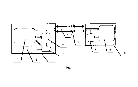
Fig. 1 presents the block diagram of the locking system, where:
1 is the key (autonomous electronic device);
2 is the control circuit, including the microcontroller of the key, which has
one of its
output signals connected to the input two OR connected for turning on/off the
power source;
3 is the energy-saving circuit of the key's battery;
4 is the specialized circuit designed to identify the signal from an external
event in order
to turn on the controlled power source;
5 is the tailpiece of the key with contacts to supply power and channel for
receiving and
sending data, including the reception of the signal from external event;
6 is the battery of the key;
7 indicates the connecting contacts of the lock and key;
8 is the energy-saving circuit in the battery of the key in the lock;
9 is the control circuit, including the microcontroller of the key, which has
one of its
output signals connected to the input two OR for turning on/off the power
source.
10 is the electronic board of the lock.
The electronic board (10) of the lock has a energy-saving circuit (8) of the
battery (6) of
the key (1) which, following the completion of the operation cycle to identify
the key (1) (in
case of entering a wrong authorization access code), disconnects the control
circuit (9) of the
lock (including the microcontroller) from the power bus in order to save power
before the key
4
CA 03203551 2023- 6- 27
Doc. No. 283-25 CA/PCT
(1) is removed. The following steps are taken to extend the time of autonomous
operation of
the key (1): the electronic control circuit of the key has a energy-saving
circuit (3) of the
battery (6) of the key (1) which, following the completion of the operation
cycle and at a
signal received from the microcontroller, switches the power source into
energy-saving mode
that completely stops the power supply from the power source to the
microcontroller and
other elements required for the operation of the key (1). A special energy-
saving circuit (8) of
the battery (6) of the key (1) used in the electronic board (10) of the key
includes a controlled
power source with a circuit OR a circuit designed to identify the signal from
an external event
in order to send such signal to the input one OR to send such signal for
turning on the
controlled power source. The energy-saving circuit (3) of the battery (6) of
the key (1)
includes a controlled power source with a circuit OR. In the power off mode,
the special
energy-saving circuit (3) of the battery (6) of the key (1) consumes the power
at a level equal
to the self-discharge of the battery, thereby maximizing the battery life. The
battery (6) is
connected to the main electronic circuit of the key (1) only after the key (1)
is inserted into the
lock cylinder, where the lock connector contacts (7) and the key (1)
communicate with each
other. The electronic board (10) of the lock is powered by the battery (6) of
the key (1) and,
by sending a special signal to the key (1) through connector contacts (7) for
power supply,
and through specialized circuit (4) designed to identify the powering on
attribute in an
external event, and by using a special energy-saving circuit (3), it activates
an electric signal
fed to the input one OR fed for switching the power source to the operation
mode for the time
that will be sufficient to start the microcontroller and, in this case, the
specialized circuit (4)
designed to identify the powering on attribute in an external event does not
use the power of
the battery. The power source supplies the power to the control circuit (2)
which, after the
first initialization of the microcontroller, sends an output signal to the
input two OR sends a
signal to keep the power source turned on for the duration of the operation
cycle, after the end
of which the microcontroller receives the signal from the input two OR and
switches the
power source to energy-saving mode. In addition, the electronic board (10) of
the lock has a
energy-saving circuit (8) of the battery (6) of the key (1) which, following
the completion of
the operation cycle of the identification of the key, including a limited time
provided for
opening the lock, turns off the power of the lock control circuit supplied
from the power bus
to prevent the electronic board (10) of the key from consuming the power of
the battery (6) of
5
CA 03203551 2023- 6- 27
Doc. No. 283-25 CA/PCT
the key (1) before the key (1) is removed from the lock cylinder.
The energy-saving method for an autonomous device is used as follows: Once the
operation cycle is complete, the power source is switched into energy-saving
mode by a
command from the microcontroller, and such energy-saving mode completely
disconnects any
power supply from the battery to the microcontroller and also disconnects
other elements of
the electronic control circuit required for the operation of the device. The
controlled power
source is turned on by a low-current signal identified from the control signal
sent through the
communication interface from an external device, where the attribute of the
signal for turning
on the power source may be a certain amplitude, duration, or frequency of the
signal, and such
signal is sent through a special circuit designed to identify such powering on
attribute, which
does not use the power of the battery while activating the electric signal
from such external
low-current control signal and switching the controlled power source into the
operation mode.
The controlled power source supplies power to the control circuit, including
the
microcontroller, which controls the execution of the operation cycle. After
powering on, the
microcontroller sends a power-on signal in accordance with its logic OR sends
it to the input
of the controlled power source to continue its operation for the required
time, which is defined
by an algorithm of the program loaded into the microcontroller. Once the
operation cycle is
complete, the microcontroller removes the power-on signal sent to the input of
the controlled
power source and switches such power source into the energy-saving mode, where
the power
supply from the battery to the microcontroller and other elements of the
circuit required for
the operation of the device is completely disconnected. This includes the use
of a special
power source, which can be controlled by turning it on/off and, theoretically,
has the
minimum power consumption in the power-off mode at the level equal to the self-
discharge of
the battery (less than 1 A).
The embodiment of this method uses a circuit designed to identify, from a
control signal
sent via the external device communication interface used for exchanging the
information
with the external device, a signal (amplitude, or duration, or frequency)
which enables,
without using the power of the battery, to turn on the controlled power source
and sustain the
signal for the time sufficient for allowing the microcontroller (after it is
powered on) to
perform the first initialization, testing, and send a power-on signal in
accordance with its logic
OR send it to the input of the controlled power source in order to continue
its operation for the
6
CA 03203551 2023- 6- 27
Doc. No. 283-25 CA/PCT
required time, which is defined by an algorithm of the program loaded into the
microcontroller. Once the operation cycle is complete, the microcontroller
removes the
power-on signal sent to the input of the controlled power source and switches
such power
source into the energy-saving mode, where the power supply from the battery to
the
microcontroller and other elements of the circuit required for the operation
of the device is
completely disconnected.
The review of patent, scientific and technical literature has not revealed any
technical
solution with a similar set of essential features, which allows to conclude
that the claimed
invention meets the criterion of novelty.
The claimed set of essential features that ensure the said technical result is
not obvious
from the prior art, which allows to conclude that the claimed invention meets
the patentability
condition of inventive level.
7
CA 03203551 2023- 6- 27