Note: Descriptions are shown in the official language in which they were submitted.
WO 2022/150317
PCT/US2022/011205
NEEDLE HUB FOR DRUG DELIVERY DEVICE
CROSS-REFERENCE TO RELATED APPLICATION
[0001] This application claims priority to United States Provisional
Application No.
63/134,054, filed January 5, 2021, which is hereby incorporated by reference
in its entirety.
BACKGROUND OF THE INVENTION
Field of the Invention
[0002] The present disclosure relates to a needle hub for a drug delivery
device.
Description of Related Art
[0003] Wearable medical devices, such as automatic injectors, have the benefit
of providing
therapy to the patient at a location remote from a clinical facility and/or
while being worn
discretely under the patient's clothing. The wearable medical device can be
applied to the
patient's skin and configured to automatically deliver a dose of a
pharmaceutical composition
within a predetermined time period after applying the wearable medical device
to the patient's
skin. After the device delivers the pharmaceutical composition to the patient,
the patient may
subsequently remove and dispose of the device.
SUMMARY OF THE INVENTION
[0004] In one aspect or embodiment, a needle hub for a drug delivery device
includes a hub
body, an activation button moveable relative to the hub body, with the
activation button having
a first actuation surface, and a needle holder moveable relative to the hub
body, with the needle
holder having a second actuation surface. The first actuation surface of the
activation button
is configured to engage the second actuation surface of the needle holder. The
needle hub
further includes a needle attached to the needle holder, a needle spring
biasing the needle holder
to a retracted position where the needle is positioned within the hub body, a
cannula holder
moveable relative to the hub body and the needle holder, a cannula attached to
the cannula
holder, the cannula configured to be in fluid communication with a fluid
source, and a cannula
spring biasing the cannula holder to a retracted position where the cannula is
positioned within
the hub body. Movement of the activation button is configured to cause the
first actuation
surface of the activation button to engage the second actuation surface of the
needle holder to
move the needle holder and the cannula holder from the respective retracted
positions to
CA 03203616 2023- 6- 28
WO 2022/150317
PCT/US2022/011205
insertion positions where distal ends of the needle and the cannula are
positioned outside of the
hub body, with the needle holder configured to return to the retracted
position while the cannula
holder remains in the insertion position. Further, movement of a portion of
the hub body is
configured to disengage a connection between the cannula holder and the hub
body to allow
the cannula holder to return to the retracted position.
[0005] The needle holder may include a passageway configured to be in fluid
communication with a fluid source, with the needle in fluid communication with
the
passageway of the needle holder. At least a portion of the needle may be
received within the
cannula, and the cannula holder may include a seal engaged with the needle.
The needle hub
may include a first projection and the cannula holder may include a second
projection, with the
first projection of the needle hub engaging the second projection of the
cannula holder when
the cannula is in the insertion position to restrict movement of the cannula
holder to the
retracted position. The needle hub may include a removal tab, where movement
of the removal
tab releases an engagement between the first projection of the needle hub and
the second
projection of the cannula holder to allow the cannula spring to bias the
cannula to the retracted
position. At least a portion of the removal tab may be configured to he
engaged with a skin
surface of a person after attaching the needle hub to a person.
[0006] The actuator button may be moveable along a first axis, where the
needle holder and
the cannula holder are moveable along a second axis perpendicular to the first
axis. The first
actuation surface of the activation button may be configured to disengage from
the second
actuation surface of the needle holder after movement of the actuation button
a predetermined
distance along the first axis.
[0007] The needle hub may include a skin tenting reduction mechanism including
an
adhesive surface configured to be adhered to a skin surface of a person, with
the skin tenting
reduction mechanism configured to stretch the skin surface at a location where
the needle
penetrates the skin surface.
[0008] In one aspect or embodiment, a needle hub for a drug delivery device
includes a hub
body, an activation button moveable relative to the hub body, a needle holder
moveable relative
to the hub body, a needle attached to the needle holder, a cannula holder
moveable relative to
the hub body and the needle holder, a cannula attached to the cannula holder,
with the cannula
configured to be in fluid communication with a fluid source, a drive spring
configured to bias
the needle holder and the cannula holder from a retracted position where the
needle and the
cannula are positioned within the hub body to an insertion position where
distal ends of the
needle and the cannula are positioned outside of the hub body, and a
retraction spring
CA 03203616 2023- 6- 28
WO 2022/150317
PCT/US2022/011205
configured to retract the needle holder from the insertion position to the
retracted position.
Prior to actuation of the activation button, the drive spring is engaged with
the cannula holder,
with the needle holder engaged with the cannula holder to prevent movement of
the cannula
holder. After actuation of the activation button, the needle holder is
configured to move relative
to the hub body to allow the cannula holder to rotate relative to the needle
holder such that the
drive spring moves the cannula holder and the needle holder to the insertion
position.
[0009] The hub body may include a first cam surface and the cannula holder may
include a
second cam surface, where engagement of the second cam surface with the first
cam surface is
configured to rotate the cannula holder. The needle holder may include a first
protrusion and
the cannula holder may include a second protrusion, where, prior to actuation
of the activation
button, the first protrusion of the needle holder engages the second
protrusion of the cannula
holder to prevent rotation of the cannula holder. The activation button may be
configured to
be depressed, where depressing the activation button is configured to move the
first protrusion
of the needle holder from engagement with the second protrusion of the cannula
holder to allow
the cannula holder to rotate, the first cam surface of the hub body to
disengage from the second
cam surface of the cannula holder, and the cannula holder and the needle
holder to move to the
insertion position. After actuation of the activation button and the rotation
of the cannula
holder, a first drive surface of the cannula holder may be engaged with a
second drive surface
of the needle holder such that movement of the cannula holder toward the
insertion position
will also move the needle holder toward the insertion position. After movement
of the cannula
holder to the insertion position, the needle holder may engage a ramp portion
of the hub body
to rotate the needle holder such that the first drive surface of the cannula
holder is disengaged
from the second drive surface of the needle holder to allow the retraction
spring to bias the
needle holder back to the retracted position. The activation button may be
translatable from a
first position to a second position, where the activation button is restricted
from being depressed
when the activation button is in the first position.
(WM The needle hub may further include a needle shield
covering at least a portion of the
needle and the cannula, and a needle shield remover engaged with the hub body,
where the
needle shield remover prevents movement of the activation button. With the
needle holder in
the retracted position and the cannula holder in the insertion position, the
needle may be
positioned entirely outside of the cannula. The cannula holder may include an
inlet configured
to be in fluid communication with a fluid source, where the cannula holder
includes a seal
engaged with the needle. The drive spring may be first and second compression
springs.
3
CA 03203616 2023- 6- 28
WO 2022/150317
PCT/US2022/011205
BRIEF DESCRIPTION OF THE DRAWINGS
[0011] The above-mentioned and other features and advantages of this
disclosure, and the
manner of attaining them, will become more apparent and the disclosure itself
will be better
understood by reference to the following descriptions of embodiments of the
disclosure taken
in conjunction with the accompanying drawings.
[0012] FIG. 1 is schematic view of a drug delivery device according to one
aspect or
embodiment of the present application.
[0013] FIG. 2 is a schematic view of the drug delivery device of FIG. 1.
[0014] FIG. 3 is a perspective view of a needle hub according to one aspect or
embodiment
of the present application.
[0015] FIG. 4A is a top view of the needle hub of FIG. 3, showing an indicator
prior to use
of the needle hub.
[0016] FIG. 48 is a top view of the needle hub of FIG. 3, showing an indicator
after insertion
of a needle.
[0017] FIG. 4C is a top view of the needle hub of FIG. 3, showing an indicator
after
withdrawal of a cannula.
[0018] FIG. 5 is a schematic view showing a method of using the needle hub of
FIG. 3.
[0019] FIG. 6N is a schematic view of the needle hub of FIG. 3, showing
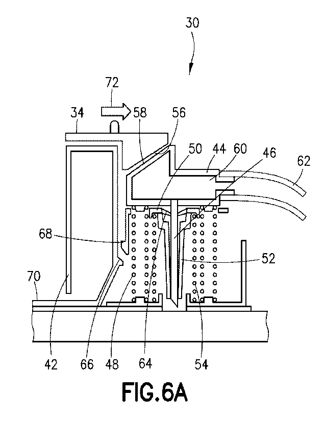
actuation of an
activation button.
[0020] FIG. 6B is a schematic view of the needle hub of FIG, 3, showing
movement of a
needle and a cannula from a retracted position to an insertion position.
[0021] FIG. 6C is a schematic view of the needle hub of FIG. 3, showing a
needle in a
retracted position and a cannula in an insertion position.
[0022] FIG. 6D is a schematic view of the needle hub of FIG. 3, showing
movement of a
cannula to a retracted position.
[0023] FIG. 7 is a perspective view of a needle hub according to a further
aspect or
embodiment of the present application.
[0024] FIG. 8 is a front view of the needle hub of FIG. 7, showing an infusion
mode.
[0025] FIG. 9 is a front view of the needle hub of FIG. 7, showing a cannula
withdrawal.
[0026] FIG. 10 is a perspective view of a needle hub according to a further
aspect or
embodiment of the present application.
[0027] FIG. 11 is a schematic view showing a method of using the needle hub of
FIG. 7.
[0028] FIG. 12A is a schematic view of the needle hub of FIG. 7, showing a pre-
use position
of the needle hub.
4
CA 03203616 2023- 6- 28
WO 2022/150317
PCT/US2022/011205
[0029] FIG. 12B is a schematic view of the needle hub of FIG. 7, showing the
needle hub
being actuated.
[0030] FIG. 12C is a schematic view of the needle hub of FIG. 7, showing a
needle being
retracted.
[0031] FIG. 12ll is a schematic view of the needle hub of FIG. 7, showing a
needle in a
retracted position.
[0032] FIG. 12E is a schematic view of the needle hub of FIG. 7, showing an
applicator
being detached from the needle hub.
[0033] FIG. 12F is a schematic view of the needle hub of FIG. 7, showing a
cannula in a
retracted position.
[0034] FIG. 13 is a cross-sectional view of a needle hub according to a
further aspect or
embodiment of the present application.
[00351 FIG. 14 is a cross-sectional view of the needle hub of FIG. 13,
[0036] FIG. 15 is a perspective view of a needle hub according to a further
aspect or
embodiment of the present application.
[0037] FIG. 16 is a perspective view of a needle hub according to a further
aspect or
embodiment of the present application.
[0038] FIG. 17 is a perspective view of a needle actuation assembly according
to one aspect
or embodiment of the present application.
[0039] FIG. 18A is a cross-sectional view of the needle hub of FIG. 15,
showing a cannula
insertion position.
[0040] FIG. 18B is a cross-sectional view of the needle hub of FIG. 15,
showing a cannula
retraction position.
[0041] FIG. 19 is a perspective view of a needle hub according to a further
aspect or
embodiment of the present application.
[0042] FIG. 20 is a schematic view showing a method of using the needle hub of
FIG. 19.
[0043] FIG. 21 is a perspective view of a needle actuation assembly according
to a further
aspect or embodiment of the present application.
[0044] FIG. 22 is a perspective view of a drug delivery device and needle hub
according to
a further aspect or embodiment of the present application.
[0045] FIG. 23 is an exploded perspective view of the drug delivery device and
needle hub
of FIG. 22.
[0046] FIG. 24 is a perspective view of the drug delivery device and needle
hub of FIG. 2.2,
showing the drug delivery device and needle hub connected while delivering a
medicament.
CA 03203616 2023- 6- 28
WO 2022/150317
PCT/US2022/011205
[0047] FIG. 25 is a perspective view of the drug delivery device and needle
hub of FIG. 22,
showing the needle hub separated from the drug delivery device while
delivering a
medicament.
[0048] FIG. 26A is a cross-sectional view of a needle hub according to a
further aspect or
embodiment of the present application, showing an initial position of the
needle hub.
[0049] FIG. 26B is a cross-sectional view of a needle hub according to a
further aspect or
embodiment of the present application, showing engagement with a skin surface.
[0050] FIG. 26C is a cross-sectional view of a needle hub according to a
further aspect or
embodiment of the present application, showing insertion of a needle.
[0051] FIG. 27A is a cross-sectional view of a needle hub according to a
further aspect or
embodiment of the present application, showing an initial position of the
needle hub.
[0052] FIG. 27B is a cross-sectional view of a needle hub according to a
further aspect or
embodiment of the present application, showing engagement with a skin surface,
[0053] FIG. 27C is a cross-sectional view of a needle hub according to a
further aspect or
embodiment of the present application, showing insertion of a needle.
[0054] FIG. 28A is a cross-sectional view of a needle hub according to a
further aspect or
embodiment of the present application, showing an initial position of the
needle hub.
[0055] FIG. 28B is a cross-sectional view of a needle hub according to a
further aspect or
embodiment of the present application, showing engagement with a skin surface.
[0056] FIG. 28C is a cross-sectional view of a needle hub according to a
further aspect or
embodiment of the present application, showing insertion of a needle.
[0057] FIG. 29 is a perspective view of a needle actuation assembly according
to a further
aspect or embodiment of the present application, showing an unactuated
position.
[0058] FIG. 30 is a perspective view of the needle actuation assembly of FIG.
29, showing
an actuated position.
[0059] FIG. 31 is a cross-sectional view of the needle actuation assembly of
FIG. 29,
showing an unactuated position.
[0060] FIG. 32 is a cross-sectional view of the needle actuation assembly of
FIG. 29,
showing an actuated position.
[0061] FIG. 33 is a cross-sectional view of the needle actuation assembly of
FIG. 29,
showing a retracted position.
[0062] FIG. 34 is a perspective view of a needle hub according to a further
aspect or
embodiment of the present application.
[0063] FIG. 35 is a schematic view of the needle hub of FIG. 34.
6
CA 03203616 2023- 6- 28
WO 2022/150317
PCT/US2022/011205
[0064] FIG. 36 is a perspective view of a drug delivery device according to a
further aspect
or embodiment of the present application.
[0065] FIG. 37 is a front view of the drug delivery device of FIG. 36.
[0066] FIG. 38 is a front view of the drug delivery device of FIG. 36. showing
a reservoir
separated from the drug delivery device.
[0067] FIG. 39 is a front view of the drug delivery device of FIG. 36, showing
the drug
delivery device attached to a patient.
[0068] FIG. 40 is a partial cross-sectional view of a prior art valve
assembly.
[0069] FIG. 41 is a front cross-sectional view of a needle hub for a drug
delivery device
according to a further aspect or embodiment of the present application.
[0070] FIG. 42 is a cutaway perspective view of the needle hub of FIG. 41.
[0071] FIG. 43 is a cutaway perspective view of the needle hub of FIG. 41,
showing a needle
shield remover.
[0072] FIG. 44 is a side cross-sectional view of the needle hub of FIG. 41,
showing a pre-
use position of the needle huh
[0073] FIG. 45 is a side cross-sectional view of the needle hub of FIG. 41,
showing a needle
shield remover removed from the needle hub.
[0074] FIG. 46 is a side cross-sectional view of the needle hub of FIG. 41,
showing initial
movement of an activation button.
[0075] FIG. 47 is a partial perspective view of the needle hub of FIG. 41,
showing an
activation button according to one aspect or embodiment of the present
application.
[0076] FIG. 48 is a partial perspective view of the needle hub of FIG. 41,
showing a retracted
position of a needle holder and cannula holder.
[0077] FIG. 49 is a side cross-sectional view of the needle hub of FIG. 41.
showing an
activation button being depressed.
[0078] FIG. 50 is a partial perspective view of the needle hub of FIG. 41,
showing an
activation button being depressed.
[0079] FIG. 51 is a side cross-sectional view of the needle hub of FIG. 41,
showing a needle
holder and a cannula holder in an insertion position.
[0080] FIG. 52 is a partial perspective view of the needle hub of FIG. 41,
showing initial
rotation of a needle holder.
[0081] FIG. 53 is a partial perspective view of the needle hub of FIG. 41,
showing final
rotation of a needle holder.
7
CA 03203616 2023- 6- 28
WO 2022/150317
PCT/US2022/011205
[0082] FIG. 54 is a side cross-sectional view of the needle hub of FIG. 41,
showing a needle
holder in a retracted position and a cannula holder in an insertion position.
[0083] FIG. 55 is an enlarged perspective view of the area shown in FIG. 54.
[0084] Corresponding reference characters indicate corresponding parts
throughout the
several views. The exemplifications set out herein illustrate exemplary
embodiments of the
disclosure, and such exemplifications are not to be construed as limiting the
scope of the
disclosure in any manner.
DETAILED DESCRIPTION OF THE INVENTION
[0085] Spatial or directional terms, such as "left", "right", "inner",
"outer", "above",
"below", and the like, are not to be considered as limiting as the invention
can assume various
alternative orientations,
[0086] All numbers used in the specification and claims are to be understood
as being
modified in all instances by the term "about". By "about" is meant a range of
plus or minus
ten percent of the stated value. As used in the specification and the claims,
the singular form
of "a", "an", and "the" include plural referents unless the context clearly
dictates otherwise.
The terms "first", "second", and the like are not intended to refer to any
particular order or
chronology, but instead refer to different conditions, properties, or
elements. By "at least" is
meant "greater than or equal to".
[0087] Referring to FIGS. 1-3, a drug delivery device 10 includes a reservoir
12, a power
module 14, an insertion mechanism 16, control electronics 18, and a housing
20. In one aspect
or embodiment, the drug delivery device 1.0 is a wearable automatic injector.
The drug delivery
device 10 may be mounted onto the skin of a patient and triggered to inject a
pharmaceutical
composition from the reservoir 12 into the patient. The drug delivery device
10 may be pre-
filled with the pharmaceutical composition, or it may be filled with the
pharmaceutical
composition by the patient or medical professional prior to use. The control
electronics 18 may
include a processor 22, such as a microcontroller, a motor driver 23, a
sensing module 24, a
visual driver 25, and/or audio driver 26. The drug delivery device 10 includes
a drive
mechanism 27 configured to dispense fluid from the reservoir 1.2. The drive
mechanism 27
may be motor powered, spring powered, hydraulic powered, pneumatic powered.
and/or other
suitable drive mechanism.
[0088] The drug delivery device 10 is configured to deliver a dose of a
pharmaceutical
composition, e.g., any desired medicament, into the patient's body by a
subcutaneous injection
at a slow, controlled injection rate. Exemplary time durations for the
delivery achieved by the
8
CA 03203616 2023- 6- 28
WO 2022/150317
PCT/US2022/011205
drug delivery device 10 may range from about 5 minutes to about 60 minutes,
but are not
limited to this exemplary range. Exemplary volumes of the pharmaceutical
composition
delivered by the drug delivery device 10 may range from about 10 milliliters
to about 50
milliliters, but are not limited to this exemplary range. The volume of the
pharmaceutical
composition delivered to the patient may be adjusted. The drug delivery device
10 may
communicate with another device, such as a mobile device or computer,
[0089] Referring to FIGS. 3-6D. according to one aspect or embodiment, the
insertion
mechanism 16 includes a needle hub 30 separate from the housing 20. The needle
hub 30
includes a removal tab 3.2, an activation button 34, a status indicator 36, a
finger grip, side
grips, and an integrated cannula withdrawal tab 38. The needle hub 30 includes
an in-dwelling
cannula. The status indicator 36 may be white when unused (FIG. 4A), blue when
the needle
has been inserted and ready to infuse (FIG. 4B), and green when the cannula
has been
withdrawn (FIG. 4C), As shown in FIG. 5, the needle hub 30 is used by removing
the
packaging, removing an adhesive liner from the bottom of the needle hub 30,
attaching the
needle hub 30 to a skin surface, and squeezing the activation button 34, which
causes the needle
to automatically retract leaving an in-dwelling cannula in the patient. The
medicament or fluid
is then infused into the patient. Once the infusion is complete, the cannula
withdrawal tab 38
is pulled, which retracts the cannula. The needle hub 30 can then be removed
from the skin of
the patient.
[0090] Referring to FIGS. 6A-6D, in one aspect or embodiment, the needle hub
30 includes
a hub body 42, the activation button 34, a needle holder 44, a needle 46
attached to the needle
holder 44, a needle spring 48, a cannula holder 50, a cannula 52 attached to
the cannula holder
50, and a cannula spring 54. The activation button 34 is moveable relative to
the hub body 42
and has a first actuation surface 56. The needle holder 44 is moveable
relative to the hub body
42 and has a second actuation surface 58. The first actuation surface 56 of
the activation button
34 is configured to engage the second actuation surface 58 of the needle
holder 44. The needle
spring 48 biases the needle holder 44 to a retracted position where the needle
46 is positioned
within the hub body 42. The cannula holder 50 is moveable relative to the hub
body 42 and
the needle holder 44. The cannula 52 is configured to be in fluid
communication with a fluid
source, such as the fluid reservoir 12. The cannula spring 54 biases the
cannula holder 50 to a
retracted position where the cannula 52 is positioned within the hub body 42.
Movement of
the activation button 34 is configured to cause the first actuation surface 56
of the activation
button 34 to engage the second actuation surface 58 of the needle holder 44 to
move the needle
holder 44 and the cannula holder 50 from the respective retracted positions to
insertion
9
CA 03203616 2023- 6- 28
WO 2022/150317
PCT/US2022/011205
positions where distal ends of the needle 46 and the cannula 52 are positioned
outside of the
hub body 42, with the needle holder 44 configured to return to the retracted
position while the
cannula holder 50 remains in the insertion position. Movement of a portion of
the hub body
42 is configured to disengage a connection between the cannula holder 50 and
the hub body 42
to allow the cannula holder 50 to return to the retracted position.
[0091] Referring again to FIGS. 6A-6D, the needle holder 44 includes a
passageway 60
configured to be in fluid communication with the fluid reservoir 12, with the
needle 46 in fluid
communication with the passageway 60 of the needle holder 44. At least a
portion of the needle
46 is received within the cannula 52. Fluid is configured to flow from the
fluid reservoir 12
via tubing 6.2 to the passageway 60 of the needle holder 44, through the
needle 46, and into the
cannula 52. The cannula holder 50 includes a seal 64 engaged with the needle
46. The needle
hub 30 includes a first projection 66 and the cannula holder 50 includes a
second projection 68,
with the first projection 66 of the needle hub 66 engaging the second
projection 68 of the
cannula holder 50 when the cannula 52 is in the insertion position to restrict
movement of the
cannula holder 50 to the retracted position.
[0092] Referring to FIGS. 3-6D, the needle hub 30 includes a removal tab 70,
where
movement of the removal tab 70 releases an engagement between the first
projection 66 of the
needle hub 30 and the second projection 68 of the cannula holder 50 to allow
the calm ula spring
54 to bias the cannula 52 to the retracted position. At least a portion of the
removal tab 70 is
configured to be engaged with a skin surface of a person after attaching the
needle hub 30 to a
person. The actuator button 34 is moveable along a first axis 72, and the
needle holder 44 and
the cannula holder 50 are moveable along a second axis 74 perpendicular to the
first axis 72.
The first actuation surface 56 of the activation button 34 is configured to
disengage from the
second actuation surface 58 of the needle holder VI after movement of the
actuation button 34
is a predetermined distance along the first axis 72.
[0093] Referring to FIGS. 7-14, a needle hub 80, according to a further aspect
or
embodiment, includes an applicator 82 having a needle holder 84, a needle 86
attached to the
needle holder 84, a needle retraction spring 88, and an activation button 90,
and a hub body 92
having a cannula holder 94, a cannula 96 attached to the cannula holder 94, a
cannula
withdrawal button 98, and a cannula retraction spring 100. At least a portion
of the hub body
92 is configured to be received within the applicator 82 and the applicator 82
is configured to
be separated from the hub body 92. Movement of the activation button 90 is
configured to
move the needle holder 84 and the cannula holder 94 from a retracted position,
where the needle
86 and the cannula 96 are positioned within the applicator 82 or hub body 92,
to an insertion
CA 03203616 2023- 6- 28
WO 2022/150317
PCT/US2022/011205
position, where distal ends of the needle 86 and the cannula 96 are positioned
outside of the
applicator 82 and hub body 92. The cannula withdrawal button 98 locks the
cannula holder 94
in the insertion position against a biasing force of the cannula retraction
spring 100 when the
cannula holder 94 is moved from the retracted position to the insertion
position. As shown in
FIG. 10, in one aspect or embodiment, the cannula withdrawal button 98 may be
omitted.
[0094] Referring to FIGS. 1.2A-12F, the needle holder 84 is configured to move
to the
retracted position after movement of the cannula holder 94 to the insertion
position. The
activation button 90 includes an extension 102 having a drive protrusion 103
and the applicator
82 includes a drive surface 104 configured to engage the drive protrusion 103.
Upon movement
of the activation button 90, the drive protrusion 103 engages the needle
holder 84 to move the
needle holder 84 and the cannula holder 94 to the insertion position, with the
drive protrusion
103 engaging the drive surface 104 of the applicator 82 to move the extension
102 radially
outward thereby releasing the needle holder 84 from the drive protrusion 103
to allow the
needle retraction spring 100 to return the needle holder 84 to the retracted
position. Actuation
of the cannula withdrawal button 98 is configured to move the cannula holder
94 from the
insertion position to the retracted position. The hub body 92 further includes
an adhesive pad
105 configured to secure the hub body 92 to a skin surface of a person. The
adhesive pad 105
includes a removal tab 106 extending radially outward from the hub body 92.
The activation
button 90 is received within an opening 107 defined by a body 108 of the
applicator 82. The
cannula holder 94 includes a port 109 configured to be in fluid communication
with the fluid
reservoir 12, with the cannula 96 in fluid communication with the port 109.
Tubing 110 is
connected to the port of the cannula holder 94.
[0095] Referring to FIG. Ii. in one aspect or embodiment, the needle hub 80 is
used by
removing the packaging, removing an adhesive liner, attaching the needle hub
80 to a skin
surface of a patient and removing a safety cap, and pressing the activation
button 90 of the
applicator 82, which automatically actuates and retracts the needle 86 to
leave the in-dwelling
cannula 96. The applicator 82 can then be removed from the hub body 92 and the
infusion can
commence. Once the infusion is complete, the cannula withdrawal button 98 may
be pressed
to remove the cannula 96 from the patient, with the hub body 92 being removed
from the skin
of the patient using the removal tab 106.
[0096] Referring to FIGS. 13 and 14, in one aspect or embodiment, the cannula
holder 94
includes a portion of the adhesive pad 105, which removes a portion of the
adhesive pad 105
from the skin of the patient when the cannula holder 94 is removed from the
hub body 92 to
facilitate easier removal of the remainder of the adhesive pad 105 from the
skin of the patient.
11
CA 03203616 2023- 6- 28
WO 2022/150317
PCT/US2022/011205
[0097] Referring to FIGS. 15-18B, a needle hub 112 according to a further
aspect or
embodiment, includes a hub body 114, an activation button 116, a needle holder
118 and a
needle 120 attached to the needle holder 118, a cannula holder 122 and a
cannula 124 attached
to the cannula holder 122, a needle actuation mechanism 126, and a cannula
spring 128. The
needle actuation mechanism 126 is configured to move the needle holder 118 and
the cannula
holder 1.22 from a retracted position to an insertion position and is
configured to move the
needle holder 118 back to the retracted position. The needle actuation
mechanism 126 includes
a cam track 130, a cam member 132 received within the cam track 130, and a
torsion spring
134. The torsion spring 134 biases the cam member 132 relative to the cam
track 130. The
cannula spring 128 biases the cannula holder 122 to a retracted position.
Movement of the
activation button 116 is configured to cause the needle holder 118 and the
cannula holder 122
to move from the retracted position to the insertion position, with the needle
holder 118
configured to return to the retracted position while the cannula holder 122
remains in the
insertion position. As shown in FIG. 16, in one aspect or embodiment, the
needle hub 112
includes two lateral activation squeeze buttons 116. The needle hub 112 is
used in the same
manner as described above in connection with the needle hub 30 shown in FIG.
5.
[0098] Referring to FIGS. 1T18B, the hub body 114 includes a cannula lock 136
configured
to lock the cannula holder 122 in the insertion portion. The needle hub 112
includes an
adhesive pad 138 configured to secure the hub body 114 to a skin surface of a
person, with the
adhesive pad 138 including a removal tab 140. Movement of the removal tab 140
is configured
to disengage the cannula lock 136 and the hub body 114 to allow the cannula
holder 122 to
return to the retracted position. The cannula lock 136 is biased away from the
cannula holder
122 via a lock spring 142, where the hub body 112 includes a hinged portion
144, with the
hinged portion 144 configured to rotate upon movement of the removal tab 140
and disengage
from the cannula lock 136. The cannula holder 122 includes a port 146
configured to be in
fluid communication with the fluid reservoir 12, with the cannula 124 in fluid
communication
with the port 146. The needle hub 112 includes tubing 148 connected to the
port 146 of the
cannula holder 122. The cannula holder 122 includes a seal 150 engaged with
the needle 120,
with at least a portion of the needle 120 received within the cannula 124.
[0099] Referring to FIGS. 19-21, a needle hub 152, according to a further
aspect or
embodiment, includes a needle holder 154 and a needle 156 attached to the
needle holder 154,
a needle actuation assembly 158 configured to move the needle holder 154 from
a retracted
position, to an insertion position, and back to the retracted position, and a
pressure interlock
160 including an inlet 162 configured to be in fluid communication with the
fluid reservoir 12,
12
CA 03203616 2023- 6- 28
WO 2022/150317
PCT/US2022/011205
an outlet 164 in fluid communication with the needle 156, and a lock member
166. The lock
member 166 has a first position where the lock member 166 prevents actuation
of the needle
actuation assembly 158 and a second position where the lock member 166 allows
actuation of
the needle actuation assembly 158. The lock member 166 is moved from the first
position to
the second position based on a pressure within the pressure interlock 160.
[00100] Referring to FIG. 21, the lock member 166 isolates the inlet 162 from
the outlet 164
when the lock member 166 is in the first position, and the lock member 166
allows fluid
communication between the inlet 162 and the outlet 164 when the lock member
166 is in the
second position. The needle hub 152 further includes tubing 168 connected to
the outlet 164
and in fluid communication with the needle 156. The lock member 166 comprises
an opening
170, with a portion of the needle actuation assembly 158 extending through the
opening 170
of the lock member 166 when the lock member 166 is in the second position. The
needle
actuation assembly 158 includes a cam track 172, a cam member 174, and an
actuation spring
176 biasing the cam member 174 relative to the cam track 172. A cam block 178
defines the
cam track 172, with the cam block 178 extending through the opening 170 of the
lock member
166 when the lock member 166 is in the second position. The needle actuation
assembly 158
further includes a cannula 180, where the needle 156 is received within the
cannula 180 when
the needle holder 154 is in the retracted position.
[00101] Referring again to FIGS. 19-21, the needle hub 152 includes a housing
182 and a
removal tab 184. A top surface 186 of the housing 182 is smooth and free of
activation buttons.
As shown in FIG. 20, the needle hub 152 is used by removing packaging,
removing an adhesive
liner, attaching the needle hub 152 to a skin surface of a patient, and
activating the drive
mechanism 27 to insert the needle 156, with the needle 156 automatically
retracting leaving
the in-dwelling cannula 180. After infusion is complete, the needle hub 152 is
removed by
grasping the removal tab 184 and lifting upwards, with the cannula 180
automatically
retracting. In one aspect or embodiment, pulling the removal tab 184 causes a
drop in pressure
of the pressure interlock 160 to cause the cannula holder and/or the cannula
180 to
automatically retract.
[00102] Referring to FIGS. 22-25, a drug delivery device 190 and a needle hub
192,
according to a further aspect or embodiment, is shown. The drug delivery
device 190 may be
similar to the drug delivery device 10 shown in FIGS. 1 and 2. The drug
delivery device 190
and the needle hub 192 of FIGS. 22-25, however, is modular, with the needle
hub 192
optionally integrated within the drug delivery device 190 (FIG. 24) or with
the needle hub 192
separated from the drug delivery device 190 and separately attached to a skin
surface of a
13
CA 03203616 2023- 6- 28
WO 2022/150317
PCT/US2022/011205
patient (FIG. 25). In one aspect or embodiment, the drug delivery device 190
and the needle
hub 192 may remain connected or integral for lower drug volume and separated
with a fluid
connection therebetween for larger drug volumes.
[00103] Referring to FIGS. 26A-26C, a needle hub 200 with a skin tenting
reduction feature.
according to one aspect or embodiment, is shown. The needle hub 200 includes a
rotating
engagement mechanism 202, with a portion of the rotating engagement mechanism
202 first
contacting a skin surface of the patient and adhering to the skin surface and
further rotating as
the needle hub 200 is fully pressed onto the skin surface. The initial
adherence and further
rotation of the rotating engagement mechanism stretches the skin to reduce
skin tenting.
[00104] Referring to FIGS. .27A-27C, a needle hub 204 with a skin tenting
reduction feature,
according to one aspect or embodiment, is shown. The needle hub 204 includes
an adhesive
ring 206 that is pressed onto the skin prior to insertion of a needle when an
activation button is
depressed or actuated. The adhesive ring 206 stretches the skin to reduce skin
tenting.
[00105] Referring to FIGS. 28A-28C, a needle hub 208 with a skin tenting
reduction feature,
according to one aspect or embodiment, is shown. The needle hub 208 includes a
skin
stretching member 210 that is moved radially outward after being initially
adhered to a skin
surface of a patient. An activation button 212 engages the skin stretching
member 210 to move
the skin stretching member 210 radially outward, which stretches the skin
locally to reduce
skin tenting.
[00106] The skin tenting reduction features and associated mechanisms of FIGS,
26A-28C
may be incorporated into any of the aspect or embodiments of the needle hub or
needle insertion
arrangements disclosed herein.
[00107] Referring to FIGS. 29-33, a needle actuation assembly 2.20, according
to one aspect
or embodiment, includes a clip 222 that holds a needle actuator body 224 and
cannula body
226 in the retracted position, which are biased by a spring 228. Pushing the
clip 222 inwards
releases the needle actuator body 224 and cannula body 226 to cause insertion
of a needle 230
and a cannula 232. When the cannula body 226 reaches the bottom of a housing
233, the
cannula body 226 contacts angled features causing the cannula body 226 to
rotate and/or twist.
The cannula body 226 is held down by clips 236 in the walls of the housing
233. After the
cannula body 226 rotates and/or twists, the needle actuator body 224 is
released and a return
spring 238 retracts the needle 230.
[00108] Referring to FIGS. 34 and 35, a needle hub 240, according to a further
aspect or
embodiment, is configured to be decoupled from remaining components of a drug
delivery
device. The needle hub 240 includes a protective cap 242, a needle insertion
mechanism 244,
14
CA 03203616 2023- 6- 28
WO 2022/150317
PCT/US2022/011205
a connection arrangement 246 configured to place the needle hub 240 in fluid
communication
with the reservoir 12 and the drive mechanism 27, a fluid path 248, and an
adhesive pad and/or
layer 250. The connection arrangement 246 may provide for aseptic connection
between the
needle hub 240 and the reservoir 12. The needle retraction may be manually
activated or
automatically activated via a triggering mechanism connected to an end of dose
event and/or a
wireless connection between the driving unit and the needle hub 240. The
triggering
mechanism may include a flexible rigid connection to plunger rod movement
(totally or
partially at the end of translation). The fluid path 248 and connection
arrangement 246 is
maintained sterile until the connection is established, with sterilization of
the sub-system and
the reservoir 1.2.
[00109] Referring to FIGS. 36-39, a drug delivery device 252, according to a
further aspect
or embodiment, includes a flexible reservoir 254, with at least a portion of
the flexible reservoir
254 positioned externally from a remaining portion of the drug delivery device
252. The drug
delivery device 252 may be similar to the drug delivery device 10 shown in
FIGS. 1 and 2. As
shown in FIG. 39, for smaller volumes, such as 10 mL-30 mL, the flexible
reservoir 254 may
be directly attached to the drug delivery device 252 and worn on a skin
surface of the patient.
As shown in FIG. 38, for larger volumes, such as 50 mL, the flexible reservoir
254 may be
separated from the drug delivery device 252 and fluidly connected to the drug
delivery device
252 via a fluid path 256, such as a tube. The flexible reservoir 254 may be
separately attached
to the patient via a belt clip, harness, strap, or other suitable arrangement.
[00110] Referring to FIG. 40, the drug delivery devices in any of the aspects
or embodiments
discussed above may utilize a valve assembly 260 that engages a reservoir
and/or container to
facilitate the fluid connection between the reservoir and/or container and the
fluid path to the
needle and/or cannula. The valve assembly 260 may be similar to and operate in
the same
manner as the valve assembly shown and described in U.S. Patent Application
Publication No.
2017/0354788.
(00111] Referring to FIGS. 41-54, in a further aspect or embodiment, a needle
hub 270 for
a drug delivery device includes a hub body 272, an activation button 274
moveable relative to
the hub body 272, a needle holder 276 moveable relative to the hub body 272, a
needle 278
attached to the needle holder 276, a cannula holder 280 moveable relative to
the hub body 272
and the needle holder 276, a cannula 282 attached to the cannula holder 280,
with the cannula
282 configured to be in fluid communication with a fluid source, such as the
reservoir 12, a
drive spring 284 configured to bias the needle holder 276 and the cannula
holder 280 from a
retracted position where the needle 278 and the cannula 282 are positioned
within the hub body
CA 03203616 2023- 6- 28
WO 2022/150317
PCT/US2022/011205
272 to an insertion position where distal ends of the needle 278 and the
cannula 282 are
positioned outside of the hub body 272, and a retraction spring 286 configured
to retract the
needle holder 276 from the insertion position to the retracted position. Prior
to actuation of the
activation button 274, the drive spring 284 is engaged with the cannula holder
280, with the
needle holder 276 engaged with the cannula holder 280 to prevent movement of
the cannula
holder 280. After actuation of the activation button 274, the needle holder
276 is configured
to move relative to the hub body 272 to allow the cannula holder 280 to rotate
relative to the
needle holder 276 such that the drive spring 284 moves the cannula holder 280
and the needle
holder 276 to the insertion position. The hub body 272 includes a first cam
surface 288 and
the cannula holder 280 includes a second cam surface .290, and where
engagement of the second
cam surface 290 with the first earn surface 288 is configured to rotate the
cannula holder 280.
The cannula holder 280 includes an inlet 292 configured to be in fluid
communication with a
fluid source, such as the fluid reservoir 12, and the cannula holder 280
includes a seal 294
engaged with the needle 278. The drive spring 284 includes first and second
compression
springs, although one or more drive springs 284 may be utilized.
[00112] Referring to FIG, 48, the needle holder .276 includes a first
protrusion 296 and the
cannula holder 280 includes a second protrusion 298, where, prior to actuation
of the activation
button 274, the first protrusion 296 of the needle holder 276 engages the
second protrusion 298
of the cannula holder 280 to prevent rotation of the cannula holder 280
[00113] Referring to FIGS. 49 and 50, the activation button 274 is configured
to be
depressed. Depressing the activation button 274 is configured to move the
first protrusion 296
of the needle holder 276 from engagement with the second protrusion 298 of the
cannula holder
280 to allow the cannula holder 280 to rotate, the first cam surface .288 of
the hub body 27.2 to
disengage from the second cam surface 290 of the cannula holder 280, and the
cannula holder
280 and the needle holder 276 to move to the insertion position. After
actuation of the
activation button 274 and the rotation of the cannula holder 280, a first
drive surface 302 of the
cannula holder 280 is engaged with a second drive surface 304 of the needle
holder 276 such
that movement of the cannula holder 280 toward the insertion position will
also move the
needle holder 276 toward the insertion position.
[00114] Referring to FIGS. 51-53, after movement of the cannula holder 280 to
the insertion
position, the needle holder 276 engages a ramp portion 306 of the hub body 272
to rotate the
needle holder 276 such that the first drive surface 302 of the cannula holder
280 is disengaged
from the second drive surface 304 of the needle holder 276 to allow the
retraction spring 286
to bias the needle holder 276 back to the retracted position.
16
CA 03203616 2023- 6- 28
WO 2022/150317
PCT/US2022/011205
[00115] Referring to FIGS. 41-49, the activation button 274 is translatable
from a first
position to a second position, with the activation button 274 restricted from
being depressed
when the activation button 274 is in the first position. As shown in FIG. 47,
the activation
button 274 or another portion of a drug delivery device may include a biasing
member 308 to
provide resistance to the activation button 274 as the activation button 274
is translated from
the first position to the second position.
[00116] Referring to FIGS. 41-44, the needle hub 270 includes a needle shield
310 covering
at least a portion of the needle 278 and the cannula. 282, and a needle shield
remover 312
engaged with the hub body 272. The needle shield remover 312 prevents movement
of the
activation button .274 when the needle shield remover 312 is engaged with the
hub body 272.
[00117] Referring to FIG. 54, with the needle holder 276 in the retracted
position and the
cannula holder 280 in the insertion position, the needle 278 is positioned
entirely outside of the
cannula 282. With the needle 278 positioned entirely outside of the cannula
282, the fluid flow
through the cannula 282 is maximized.
[00118] Although the invention has been described in detail for the purpose of
illustration
based on what is currently considered to be the most practical and preferred
embodiments, it is
to be understood that such detail is solely for that purpose and that the
invention is not limited
to the disclosed embodiments, but, on the contrary, is intended to cover
modifications and
equivalent arrangements that are within the spirit and scope of the appended
claims. For
example, it is to be understood that the present invention contemplates that,
to the extent
possible, one or more features of any embodiment can be combined with one or
more features
of any other embodiment.
17
CA 03203616 2023- 6- 28