Note: Descriptions are shown in the official language in which they were submitted.
CA 03204689 2023-06-07
WO 2022/130306
PCT/IB2021/061898
1
Respiratory System and Method
Technical Field
[0001] This disclosure relates to a system and method for controlling a
flow of
respiratory gases to a patient.
[0002] In particular, but not exclusively, the system and method controls
the flow
of respiratory gases to the patient in response to a change in the system
pressure
downstream of a flow modulator providing the flow of respiratory gases.
Background of Invention
[0003] Patients may lose respiratory function during anaesthesia, or
sedation, or
more generally during certain medical procedures. Prior to a medical procedure
a
patient may be pre-oxygenated by a medical professional to provide a reservoir
of
oxygen saturation, and this pre-oxygenation is generally carried out with a
bag
ventilator and a face mask. Once under general anaesthesia, patients must be
intubated to ventilate the patient. In some cases, intubation is completed in
30 to 60
seconds, but in other cases, particularly if the patient's airway is difficult
to traverse
(for example, due to cancer, severe injury, obesity or spasm of the neck
muscles),
intubation will take significantly longer. While pre-oxygenation provides a
buffer
against declines in oxygen saturation, for long intubation procedures, it is
necessary
to interrupt the intubation process and reapply the face mask to increase the
patient's
.. oxygen saturation to adequate levels. The interruption of the intubation
process may
happen several times for difficult intubation processes, which is time
consuming and
puts the patient at severe health risk. After approximately three attempts at
intubation
the medical procedure will be abandoned.
[0004] In procedures where multiple respiratory support systems are
required,
there may be a concern that the combination(s) of support systems could cause
excessive pressure delivery (for example when a cannula is in place on a
patient and
an anaesthetist wishes to deliver respiratory support through a mask applied
over the
top of the cannula).
CA 03204689 2023-06-07
WO 2022/130306
PCT/IB2021/061898
2
[0005] Furthermore, switching between different support systems may be
time
consuming or difficult. It may therefore be desirable to have a configuration
that
allows easy interchange between respiratory support systems, for example
support
via high flow and respiratory support via a face mask and bag or anaesthesia
machine. It may also be desirable to allow gas flows to be quickly and easily
turned
off or reduced.
[0006] A reference herein to a patent document, or any other matter
identified as
prior art, is not to be taken as an admission that the document or other
matter was
known or that the information it contains was part of the common general
knowledge
as at the priority date of any of the claims.
Summary of Invention
[0007] In one aspect of the present disclosure, there is provided a
respiratory
system for providing a flow of respiratory gases to a patient, the system
comprising: a
flow modulator; a controller configured to receive an input of a flow rate and
a
pressure of the flow of respiratory gases in the system, and configured to:
control the
flow modulator to provide the flow of respiratory gases at a target flow rate
to a
patient; and control the flow modulator to modulate the flow of respiratory
gases at a
target pressure when the pressure of the flow of respiratory gases in the
system
meets or exceeds a pressure threshold value corresponding to that target flow
rate.
[0008] In some embodiments, the target pressure comprises the pressure
threshold value corresponding to the target flow rate or a pressure threshold
value
corresponding to a flow rate less than the target flow rate.
[0009] In some embodiments, the controller is configured to control the
flow
modulator to modulate the flow of respiratory gases to the target pressure
when the
flow rate of the flow of respiratory gases is less than the target flow rate.
[0010] In some embodiments, the controller is configured to control the
flow
modulator to modulate the flow of respiratory gases to the target flow rate
when the
flow rate of the flow of respiratory gases is above the target flow rate.
[0011] In some embodiments, the controller is configured to control the
flow
modulator to the target pressure when the pressure of the flow of respiratory
gases
CA 03204689 2023-06-07
WO 2022/130306
PCT/IB2021/061898
3
exceeds the pressure threshold value corresponding to the target flow rate or
a
pressure threshold value corresponding to flow rates less than the target flow
rate.
[0012] In some embodiments, when the system begins operation from an
'off or
dormant state, the controller is configured to monitor the flow rate of the
flow of
respiratory gases in the system and is configured to control the flow
modulator to
modulate the flow of respiratory gases to the target flow rate. In some
embodiments,
the target flow rate changes over time to increase from a current value to a
flow rate
set point.
[0013] In some embodiments, the target flow rate is a flow rate set
point. The flow
rate set point may determined by a user of the respiratory system. In some
embodiments, the flow rate set point may be set by a user providing an input
to the
controller.
[0014] In some embodiments, the controller comprises a flow rate
controller
providing a flow rate control output and a pressure controller providing a
pressure
control output, wherein the control input to the flow modulator is the minimum
of the
flow rate control output and the pressure control output.
[0015] In some embodiments, the flow modulator comprises a blower, and
the
flow rate control output and pressure control output comprise an angular
velocity of
the blower.
[0016] In some embodiments, the flow modulator comprises a proportional
valve,
and the flow rate control output and pressure control output comprise a size
of a flow
path restriction through the proportional valve.
[0017] In some embodiments, the controller is configured to receive a
flow rate
value indicative of flow rate of respiratory gases provided to the patient.
[0018] In some embodiments, the controller may be operable in a first
control
mode when the flow rate is above the target flow rate to control the flow rate
to the
target flow rate, and the controller is operable in a second control mode when
the
pressure of the flow of respiratory gases is above the pressure threshold
value
corresponding to the target flow rate or is above a or the pressure threshold
value
CA 03204689 2023-06-07
WO 2022/130306
PCT/IB2021/061898
4
corresponding to a flow rate less than the target flow rate, to control the
pressure to
the target pressure.
[0019] In some embodiments, the respiratory system comprises one or
more flow
rate sensors configured to sense a flow rate of the flow of respiratory gases
in the
system to the patient
[0020] In some embodiments, the respiratory system comprises one or
more
pressure sensors configured to sense a pressure of the flow of respiratory
gases in
the system to the patient.
[0021] In some embodiments, the controller is further configured to
receive an
.. input indicative of the flow rate of the flow of respiratory gases in the
system from the
one or more flow rate sensors, and an input indicative of the pressure of the
flow of
respiratory gases in the system from the one or more pressure sensors.
[0022] In some embodiments, the respiratory system comprises a delivery
conduit
for providing a flow of gases from the flow modulator to a patient interface,
wherein
the patient interface is configured to deliver the flow of respiratory gases
to the
patient.
[0023] In some embodiments, patient interface comprises a nasal
cannula,
optionally a non-sealing nasal cannula.
[0024] In some embodiments, the patient interface comprises a gases
delivery
side arm in fluid communication with the delivery conduit, a manifold provided
at an
end of the gases delivery side arm, and one or more nasal elements extending
from
the manifold, the one or more nasal element configured to provide the flow of
respiratory gases to one or more nares of the patient, wherein the gases
delivery side
member comprises a collapsible portion.
[0025] The collapsible portion may be operable in a first configuration in
which the
collapsible portion is in a substantially open condition, and in a second
configuration
in which the collapsible portion is in a substantially closed condition.
[0026] In some embodiments, when the controller controls the flow
modulator to
the target pressure, flow to the patient is reduced to a reduced flow rate
which is:
CA 03204689 2023-06-07
WO 2022/130306
PCT/IB2021/061898
about 15L/min or less; or about 10L/min or less; or about 10L/min; or about
5L/min to
about 10L/min or less than about 5L/min or 0L/min.
[0027] In some embodiments, the controller is configured to control the
flow
modulator to increase the flow of respiratory gases towards the target flow
rate.
5 [0028] In some embodiments, the delivery conduit further
comprises a delivery
circuit and a patient breathing circuit disposed between the delivery circuit
and the
patient interface, and wherein the patient breathing circuit is connected to
the delivery
circuit by an outlet connector.
[0029] In some embodiments, the flow modulator comprises one or more
of: a
flow generator configured to be controlled by the controller to modulate the
flow of
respiratory gases to a patient; and a proportional valve configured to be
controlled by
the controller to modulate the flow of respiratory gases.
[0030] In some embodiments, the flow generator comprises a blower
configured
to be controlled by the controller to generate the flow of respiratory gases.
[0031] In some embodiments, the respiratory system comprises an Oxygen (02)
pressure sensor configured to sense pressure in an 02 delivery circuit of the
respiratory system.
[0032] In some embodiments, the respiratory system comprises an Oxygen
(02)
flow rate sensor configured to sense flow rate of a flow of 02 in an 02
delivery circuit
of the respiratory system. In some embodiments, a proportional valve may be
disposed between the 02pre55ure sensor and the 02 flow rate sensor in the 02
delivery circuit.
[0033] In some embodiments, having a patient breathing circuit, the
patient
breathing circuit may be connected to the 02 delivery circuit and an air
delivery circuit
and the patient breathing circuit and/or the patient interface may further
comprise a
patient pressure sensor and a patient flow rate sensor. In some embodiments,
the
flow modulator comprises a blower, and the blower may be disposed in the
patient
breathing circuit before the patient pressure sensor and the patient flow rate
sensor.
CA 03204689 2023-06-07
WO 2022/130306
PCT/IB2021/061898
6
[0034] In some embodiments, the controller is in operative
communication with, or
comprises, a memory component storing one or more of a function, a curve, a
look up
table or algorithm providing a relationship between the pressure threshold
values and
corresponding flow rates.
[0035] In some embodiments, the controller is configured to control the
flow
modulator to reduce the flow of respiratory gases by a variable rate of
decrease.
[0036] In some embodiments, the relationship between the pressure
threshold
values and corresponding flow rates may be represented by a pressure limit
curve or
function defining a curve having a sigmoidal shape.
[0037] In some embodiments, the relationship between the pressure threshold
values and corresponding flow rates comprises a first pressure region, a
second
pressure region, and a transition region disposed between the first pressure
region
and the second pressure region.
[0038] In some embodiments, the first pressure region may correspond to
when
the collapsible portion is substantially in the first configuration and the
second region
may correspond to when the collapsible portion is substantially in the second
configuration.
[0039] In some embodiments, the first pressure region comprises
pressure
threshold values offset from baseline pressure values by a first pressure
margin and,
the second pressure region comprises pressure threshold values offset from
baseline
pressure values by a second pressure margin, whereby the first pressure margin
is
greater than the second pressure margin.
[0040] In some embodiments, the first and second margins provide an
offset of
the pressure threshold limit values in the first pressure region which is
substantially
parallel to an offset of the pressure threshold values in the second pressure
region of
the pressure limit curve, and the first pressure region and the second
pressure region
correspond to a minimum rate of change in the flow of respiratory gases.
[0041] In some embodiments, the gradient of the transition region of
the pressure
limit curve corresponds to a maximum rate of change in the flow of respiratory
gases.
CA 03204689 2023-06-07
WO 2022/130306
PCT/IB2021/061898
7
[0042] In some embodiments, the transition region of the pressure limit
curve
may be centred about a transition flow rate. In some embodiments, the
controller is
configured to control the flow modulator to achieve a flow of respiratory
gases at the
maximum rate of change when the pressure and the corresponding flow rate is in
the
transition region of the pressure limit curve.
[0043] In some embodiments, the first and the second pressure margins
provide a
margin for a temporary decrease in system pressure of the flow of respiratory
gases
from below the pressure threshold values without the controller controlling
the flow
modulator to increase the flow of respiratory gases.
[0044] Viewed from another aspect, the present invention provides a
respiratory
system for providing a flow of respiratory gases to a patient, the system
comprising: a
controller; and a flow modulator configured to be controlled by the controller
to
provide a flow of respiratory gases to a patient; wherein the controller is
configured to
control the flow modulator to a flow rate determined pressure set point; and
wherein
the controller is configured to control the flow modulator to limit the flow
rate of the
flow of respiratory gases up to and including a flow rate set point.
[0045] In some embodiments, the flow rate set point is set by a user of
the
respiratory system. In some embodiments, the flow rate set point may be set by
a
user providing an input to the controller.
[0046] In some embodiments, the system comprises a plurality of flow rate
determined pressure set points, to which the controller is configured to
control the
flow modulator.
[0047] In some embodiments, the flow rate determined pressure set point
is
based on the flow rate of the flow of respiratory gases.
[0048] In some embodiments, the flow rate determined pressure set point is
predetermined.
[0049] In some embodiments, the flow rate determined pressure set point
when
the flow rate of the flow of respiratory gases is at or close to the flow rate
set point, is
separated by a first margin from a normal system pressure value, wherein the
flow
rate determined pressure set point when the flow rate of the flow of
respiratory gases
CA 03204689 2023-06-07
WO 2022/130306
PCT/IB2021/061898
8
at or close to 0L/min, is separated by a second margin from a normal system
pressure value, wherein the first margin is greater than the second margin.
[0050] In some embodiments, the flow rate determined pressure set point
when
the flow rate of the flow of respiratory gases at or close to 0L/min, is
0cmH20.
[0051] In some embodiments, the flow modulator comprises a blower and/or a
proportional valve.
[0052] In some embodiments, the respiratory system further comprises
one or
more of a flow sensor, pressure sensor and a user interface.
[0053] In some embodiments, respiratory system further comprises a non-
sealing
nasal interface in fluid communication with the flow modulator and configured
to
provide the flow of respiratory gases to the patient.
[0054] In some embodiments, the non-sealing nasal interface comprises a
gases
delivery side arm, a manifold provided at an end of the gases delivery side
arm, and
one or more nasal elements extending from the manifold, the one or more nasal
element configured to provide the flow of respiratory gases to one or more
nares of
the patient, wherein the gases delivery side member comprises a collapsible
portion.
[0055] In some embodiments, the collapsible portion is operable in a
first
configuration in which the collapsible portion is in a substantially open
condition, and
in a second configuration in which the collapsible portion is in a
substantially closed
condition.
[0056] In some embodiments, the flow rate set point is more than 0
L/min,
optionally more than 0 L/min to about 120 L/min, optionally between about 20
L/min to
about 90 L/min, and optionally about 40 L/min to about 70 L/min.
[0057] In another aspect of the present disclosure, there is provided a
respiratory
system for providing a flow of respiratory gases to a patient, the system
comprising: a
controller; a flow modulator configured to be controlled by the controller to
provide a
flow of respiratory gases to a patient; wherein the controller is configured
to: receive
an input relating to a flow rate set point receive one or more pressure inputs
indicative
of system pressure corresponding to the flow of respiratory gases downstream
of the
CA 03204689 2023-06-07
WO 2022/130306
PCT/IB2021/061898
9
flow modulator; receive one or more flow rate inputs indicative of the flow of
respiratory gases downstream of the flow modulator; compare the received
pressure
and/or flow rate inputs with predetermined pressure threshold values for
corresponding flow rates and the flow rate set point; control the flow
modulator
between two control modes, wherein the first control mode comprises
controlling the
flow modulator to provide the flow of respiratory gases at the flow rate set
point when
the system pressure is below the predetermined pressure threshold values for
the
corresponding flow rates; and the second control mode comprises controlling
the flow
modulator to modulate the flow of respiratory gases to a target pressure when
the
flow rate of the flow of respiratory gases is below the flow rate set point.
[0058] In another aspect of the present disclosure, there is provided a
respiratory
system for providing a flow of respiratory gases to a patient, the system
comprising: a
controller; a flow modulator configured to be controlled by the controller to
provide a
flow of respiratory gases to a patient; wherein the controller is configured
to: receive
an input indicative of the system pressure; compare the system pressure
against one
or more pressure threshold values for corresponding flow rates; control the
flow
modulator to reduce the system pressure in response to the system pressure
meeting
or exceeding the one or more pressure threshold values for the corresponding
flow
rates; and control the flow modulator to achieve a target flow rate in
response to the
system pressure not meeting or exceeding the pressure threshold values for the
corresponding flow rates.
[0059] In another aspect of the present disclosure, there is provided a
respiratory
system for providing a flow of respiratory gases to a patient, the system
comprising: a
controller; and a flow modulator configured to be controlled by the controller
to
provide a flow of respiratory gases to a patient; wherein the controller is
configured to
control the flow modulator to a flow rate set point; and wherein the
controller is
configured to control the flow modulator to limit the pressure of the flow of
respiratory
gases up to and including a flow rate determined pressure limit.
[0060] In another aspect of the present disclosure, there is provided a
respiratory
system for providing a flow of respiratory gases to a patient, the system
comprising: a
controller; a flow modulator configured to be controlled by the controller to
provide a
flow of respiratory gases to a patient; one or more sensors configured to
determine
CA 03204689 2023-06-07
WO 2022/130306
PCT/IB2021/061898
pressure of the flow of respiratory gases in the respiratory system to the
patient,
wherein the controller is configured to: receive an input indicative of
pressure of the
flow of respiratory gases in the respiratory system from the one or more
sensors;
compare the pressure against pressure threshold values for corresponding flow
rates;
5 control the flow modulator to reduce the flow of respiratory gases in
response to the
pressure exceeding the pressure threshold values for the corresponding flow
rates;
and control the flow modulator to modulate the flow of respiratory gases in
response
to the pressure not exceeding the pressure threshold values for the
corresponding
flow rates.
10 [0061] The controller of the respiratory system may comprise a
microcontroller, a
PID (proportional¨integral¨derivative) controller or a variation of a PID
controller
where the proportional, integral and derivative elements of the controller can
be
turned on or off as needed (such as P, PI or I controllers), or some other
architecture,
configured to operate by an algorithm that is stored in a memory in
communication
with the controller to direct the operation of controllable components of the
respiratory
system. The controller thus enables the respiratory system to control one or
more
components of the respiratory system in response to a change in a pressure
and/or
flow in the system. The controller may control the flow modulator in response
to a
change in a pressure in the system. The pressure in the system may be a
pressure
downstream of the flow modulator. This contrasts with pressure relief valves
which
typically relieve pressure in the system by venting gases to atmosphere when
the
system pressure exceeds a pressure threshold. This venting of delivery gases
may be
considered a source of waste.
[0062] The controller of the respiratory system receives an input of a
pressure in
the system and determines whether the value of the pressure in the system
meets or
exceeds pressure threshold values for corresponding flow rates, which is
indicative of
an obstruction (across which there may still be some flow) or blockage (across
which
there will be no flow). In response the controller controls a component of the
respiratory system, which may modulate flow. The controller also restores
desired
.. flow to the respiratory system upon subsequent removal of the obstruction
or
blockage. The controller controlling the flow of respiratory gases to the
patient thus
reduces wastage of gases, such as Oxygen. It also potentially reduces an
undesirable
effect on a flow of respiratory gases provided to the patient via another
respiratory
CA 03204689 2023-06-07
WO 2022/130306
PCT/IB2021/061898
11
support system, for example the controller controls the flow of respiratory
gases to
minimize dilution of anaesthetic agents provided to the patient via an
anaesthetic
system that is used with the system of the present disclosure. In
circumstances as
described below where a mask may be used over a cannula, this can also be
advantageous by providing better control over the pressure acting on the
obstructed/blocked (i.e. collapsed) portion so that a user does not need to
apply more
force to the mask over the cannula than is required, and to control any
residual flow
across the collapsed portion associated with the cannula.
[0063] In some embodiments, the flow modulator comprises a flow
generator,
such as a blower, configured to be controlled by the controller to generate a
flow of
respiratory gases to a patient.
[0064] In some embodiments, the flow modulator comprises a proportional
valve
configured to be controlled by the controller to modulate the flow of
respiratory gases.
[0065] In some embodiments, the flow modulator further comprises the
proportional valve and the flow generator.
[0066] The algorithm implemented by the controller controls the flow
modulator,
such as a blower and/or the proportional valve, to provide pressure/flow
control to the
respiratory system that supplies gases to a patient during the delivery of
respiratory
support. Examples of respiratory support are mentioned above, and include
nasal
high flow, continuous positive airway pressure, and ventilation. The
respiratory
system may include more than one blower and/or more than one proportional
valve.
[0067] In some embodiments, the controller is further configured to
determine flow
rate of the flow of respiratory gases from the input indicative of pressure of
the flow of
respiratory gases.
[0068] In another embodiment, the one or more sensors comprise one or more
flow rate sensors configured to sense flow rate of the flow of respiratory
gases in the
delivery conduit to the patient. The controller is further configured to
receive an input
indicative of the flow rate of the flow of respiratory gases in the delivery
conduit from
these one or more flow rate sensors. Preferably, the input indicative of the
flow rate is
data indicative of the flow rate.
CA 03204689 2023-06-07
WO 2022/130306
PCT/IB2021/061898
12
[0069] In some embodiments, the pressure of the flow of respiratory
gases in the
respiratory system is determined from the data indicative of flow rate of the
flow of
respiratory gases in the respiratory system.
[0070] In some embodiments, the one or more sensors are configured to
sense
.. pressure of the flow of respiratory gases in the respiratory system
downstream of the
flow modulator. Preferably, the one or more sensors are located downstream of
the
flow modulator.
[0071] In some embodiments, the one or more sensors comprise one or
more
pressure sensors configured to sense pressure of the flow of respiratory gases
in the
system to the patient.
[0072] In some embodiments, the one or more sensors comprise the one or
more
pressure sensors and the one or more flow rate sensors.
[0073] In some embodiments, the pressure of the flow of the respiratory
gases in
the respiratory system is pressure of the flow of respiratory gases downstream
of the
.. flow modulator.
[0074] In some embodiments, the input indicative of pressure of the
flow of
respiratory gases in the respiratory system comprises data.
[0075] In some embodiments, the respiratory system further comprises a
delivery
conduit and a patient interface at one end of the delivery conduit, wherein
the patient
interface is configured to deliver the flow of respiratory gases to the
patient.
[0076] In some embodiments, the pressure of the flow of the respiratory
gases is
pressure of the flow of respiratory gases upstream of or at the collapsible
portion.
[0077] In an example, the patient interface is in fluid communication
with a gas
supply and the flow of gases is controlled by the flow modulator of the
respiratory
system. Examples of a gas supply include a pressurised source (such as a gas
tank,
or a hospital wall supply), a blower, a blender, or a combination thereof. The
respiratory system may also include a humidifier for humidifying gases before
they
are delivered to a patient.
CA 03204689 2023-06-07
WO 2022/130306
PCT/IB2021/061898
13
[0078] In some embodiments, the patient interface comprises an outlet
to be
received by a patient nare(s) or mouth; a gases delivery side member extending
from
a side of the outlet, wherein the gases delivery side member comprises: a
lumen for a
flow of gases from an inlet of the patient interface to the outlet; and a
collapsible
portion. For example, the patient interface is a nasal cannula and optionally
a non-
sealing nasal cannula.
[0079] In some embodiments, the collapsible portion is configured to be
in a first
configuration and collapsible from the first configuration into a second
configuration.
The flow of respiratory gases through the collapsible portion in the second
configuration is at a reduced flow rate compared to when the collapsible
portion is in
the first configuration. For example, the reduced flow rate is: about 15L/min
or less; or
about 10L/min or less; or about 10L/min; or about 5L/min to about 10L/min or
less
than about 5L/min or 0L/min.
[0080] In some embodiments, the controller is further configured to
control the
flow modulator to reduce the flow of respiratory gases to the reduced flow
rate in
response to the pressure exceeding the pressure threshold values for the
corresponding flow rates. For example, the flow of respiratory gases is
reduced to the
reduced flow rate in a stepped manner. In some embodiments, the controller is
configured to control the flow modulator to reduce pressure in the system
which in
turn reduces the flow rate of respiratory gases (as determined by the change
in
pressure and resistance to flow within the system). For example, the pressure
in the
system may be reduced by e.g. slowing operation of the flow modulator in a
stepped
manner.
[0081] In some embodiments, the controller is further configured to
control the
flow modulator to reduce the flow of respiratory gases continually towards the
reduced flow rate. Alternatively/additionally, the controller may be
configured to
control the flow modulator e.g. by slowing its operation, to reduce the
pressure in the
system continually towards a pressure target.
[0082] In some embodiments, the controller is further configured to
control the
flow modulator to modulate the flow of respiratory gases to a target flow rate
in
CA 03204689 2023-06-07
WO 2022/130306
PCT/IB2021/061898
14
response to the pressure not exceeding the pressure threshold values for the
corresponding flow rates. For example, the target flow rate may be 40 to
70L/min.
[0083] In some embodiments, the controller is further configured to
control the
flow modulator to modulate the flow of respiratory gases continually towards
the
.. target flow rate.
[0084] In some embodiments, the controller is further configured to
control the
flow modulator to increase the flow of respiratory gases towards the target
flow rate.
[0085] In an example, the flow of respiratory gases is increased to the
target flow
rate in a stepped manner. Alternatively, the controller is configured to
control the flow
.. modulator to increase the flow of respiratory gases continually towards the
target flow
rate.
[0086] In some embodiments, the delivery conduit further comprises a
delivery
circuit and a patient breathing circuit disposed between the delivery circuit
and the
patient interface, and wherein the patient breathing circuit is connected to
the delivery
circuit by an outlet connector.
[0087] In some embodiments, the delivery conduit further comprises a
delivery
circuit and a patient breathing circuit disposed between the delivery circuit
and the
patient interface, and wherein the patient breathing circuit is connected to
the delivery
circuit by an outlet connector.
[0088] In some embodiments, the controller, flow modulator, the one or more
sensors and the delivery circuit are housed within a housing, and the outlet
connector
is mounted to the housing. For example, the housing is a box.
[0089] In some embodiments, the one or more sensors comprise an Oxygen
(02)
pressure sensor configured to sense pressure of the flow of 02 to the patient
from an
02 supply in an 02 delivery circuit of the respiratory system.
[0090] In some embodiments, the one or more sensors comprise an Oxygen
(02)
flow rate sensor configured to sense flow rate of the flow of 02 to the
patient from the
02 supply.
CA 03204689 2023-06-07
WO 2022/130306
PCT/IB2021/061898
[0091] In some embodiments, the proportional valve is disposed between
the 02
pressure sensor and the 02 flow rate sensor in the 02 delivery circuit.
[0092] In some embodiments, the one or more sensors comprise an air
pressure
sensor configured to sense pressure of the flow of air to the patient from
ambient air
5 .. in an air delivery circuit of the respiratory system.
[0093] In some embodiments, the blower is disposed after the air
pressure sensor
in the air delivery circuit.
[0094] In some embodiments, the patient breathing circuit is connected
to the 02
delivery circuit and the air delivery circuit and the patient breathing
circuit and/or the
10 patient interface further comprises a patient pressure sensor and a
patient flow rate
sensor.
[0095] In some embodiments, the patient breathing circuit is connected
to the 02
delivery circuit and the air delivery circuit and the patient breathing
circuit and/or the
patient interface further comprises a patient pressure sensor and a patient
flow rate
15 sensor.
[0096] In some embodiments, the blower is disposed in the patient
breathing
circuit before the patient pressure sensor and the patient flow rate sensor.
[0097] In some embodiments, the pressure threshold values for
corresponding
flow rates form a pressure limit curve.
[0098] In some embodiments, the pressure threshold values for corresponding
flow rates form a pressure limit curve. In the embodiment, the controller is
further
configured to compare the pressure and the flow rate against the pressure
limit curve.
[0099] In some embodiments, the pressure limit curve is associated with
the flow
in the respiratory system and/or the delivery conduit being restricted.
[0100] In some embodiments, the flow modulator is configured to reduce the
flow
of respiratory gases by a variable rate of decrease corresponding to the
pressure limit
curve.
[0101] In some embodiments, the pressure limit curve is sigmoidal
shaped.
CA 03204689 2023-06-07
WO 2022/130306
PCT/IB2021/061898
16
[0102] In some embodiments, the sigmoidal shaped pressure limit curve
comprises a first pressure region, a second pressure region, and a transition
region
disposed between the first pressure region and the second pressure region.
[0103] In some embodiments, the first pressure region corresponds to
the first
configuration and the second region corresponds to the second configuration.
[0104] In some embodiments, in the first configuration, normal
operating pressure
of the flow of respiratory gases in the delivery conduit is below the pressure
limit
curve by a first pressure margin and, in the second configuration, normal
operating
pressure of the flow of respiratory gases is below the pressure limit curve by
a second
pressure margin, whereby the first pressure margin is substantially greater
than the
second pressure margin. The first and the second pressure margin can thus
provide a
margin for a temporary increase in pressure of the flow of respiratory gases
from the
normal pressure to not reduce the flow of respiratory gases.
[0195] In another embodiment, the first and the second pressure margin
provides
a margin for a temporary decrease in pressure of the flow of respiratory gases
from
the normal operating pressure to not increase the flow of respiratory gases.
[0106] In some embodiments, the first pressure region is substantially
parallel to
the second pressure region of the pressure limit curve, and the first pressure
region
and the second pressure region correspond to a minimum rate of decrease in the
flow
of respiratory gases.
[0107] In some embodiments, the transition region of the pressure limit
curve
corresponds to a maximum rate of decrease in the flow of respiratory gases.
[0108] In some embodiments, the transition region of the pressure limit
curve is
centred about a transition flow rate.
[0109] In some embodiments, the flow modulator is configured to reduce the
flow
of respiratory gases at the maximum rate of decrease when the pressure and the
corresponding flow rate is in the transition region of the pressure limit
curve.
[0110] In another aspect of the present disclosure, there is provided a
respiratory
system for providing a flow of respiratory gases to a patient, the system
comprising: a
CA 03204689 2023-06-07
WO 2022/130306
PCT/IB2021/061898
17
controller; a flow modulator configured to be controlled by the controller to
provide a
flow of respiratory gases to a patient; one or more sensors configured to
determine
pressure of the flow of respiratory gases in the respiratory system to the
patient; and
a patient interface in fluid communication with the flow modulator and
configured to
deliver the flow of respiratory gases to the patient, wherein the patient
interface
comprises: an inlet to receive the flow of respiratory gases from the flow
modulator;
an outlet to deliver the flow of respiratory gases to an airway of the
patient; and a
gases conduit comprising a collapsible portion configured to switch between a
first
configuration and a second configuration, wherein the pressure of the flow of
respiratory gases in the respiratory system when the collapsible portion is in
the
second configuration is greater than the pressure of the flow of the
respiratory gases
in the respiratory system when the collapsible portion is in the first
configuration,
wherein the controller is configured to: receive an input indicative of
pressure of the
flow of respiratory gases in the respiratory system from the one or more
sensors;
compare the pressure against a pressure threshold; control the flow modulator
to
provide a first modulation of the flow of respiratory gases in response to the
pressure
meeting or exceeding the pressure threshold; and control the flow modulator to
provide a second modulation of the flow of respiratory gases in response to
the
pressure not meeting or exceeding the pressure threshold.
[0111] In some embodiments, the second modulation is different from the
first
modulation.
[0112] In some embodiments, the first modulation comprises reducing or
maintaining the flow of the respiratory gases.
[0113] In some embodiments, the first modulation comprises reducing the
flow of
the respiratory gases in response to the pressure exceeding the pressure
threshold.
[0114] In some embodiments, the first modulation comprises reducing or
maintaining the flow of the respiratory gases in response to the pressure
meeting the
pressure threshold.
[0115] In some embodiments, the second modulation comprises increasing
the
flow of respiratory gases.
CA 03204689 2023-06-07
WO 2022/130306
PCT/IB2021/061898
18
[0116] In some embodiments, the second modulation comprises modulating
the
flow of respiratory gases to a target flow rate.
[0117] In some embodiments, the one or more sensors are located
downstream of
the flow modulator.
[0118] In some embodiments, the respiratory system further comprises a
delivery
conduit configured to deliver the flow of respiratory gases to the patient
interface from
the flow modulator.
[0119] In some embodiments, the delivery conduit further comprises a
delivery
circuit and a patient breathing circuit disposed between the delivery circuit
and the
patient interface, and wherein the patient breathing circuit is connected to
the delivery
circuit by an outlet connector.
[0120] In some embodiments, the controller, flow modulator, the one or
more
sensors and the delivery circuit are housed within a housing, and the outlet
connector
is mounted to the housing.
[0121] In some embodiments, the flow modulator comprises a flow generator
configured to be controlled by the controller to generate a flow of
respiratory gases to
a patient.
[0122] In some embodiments, the flow modulator comprises a proportional
valve
configured to be controlled by the controller to modulate the flow of
respiratory gases.
[0123] In some embodiments, the flow modulator further comprises the
proportional valve and the flow generator.
[0124] In some embodiments, the flow generator comprises a blower
configured
to be controlled by the controller to generate the flow of respiratory gases.
[0125] In some embodiments, the one or more sensors comprise an Oxygen
(02)
pressure sensor configured to sense pressure of the flow of 02 to the patient
from an
02 supply in an 02 delivery circuit of the respiratory system.
CA 03204689 2023-06-07
WO 2022/130306
PCT/IB2021/061898
19
[0126] In some embodiments, the one or more sensors comprise an Oxygen
(02)
flow rate sensor configured to sense flow rate of the flow of 02 to the
patient from the
02 supply.
[0127] In some embodiments, the proportional valve is disposed between
the 02
pressure sensor and the 02 flow rate sensor in the 02 delivery circuit.
[0128] In some embodiments, the one or more sensors comprise an air
pressure
sensor configured to sense pressure of the flow of air to the patient from
ambient air
in an air delivery circuit of the respiratory system.
[0129] In some embodiments, the blower is disposed after the air
pressure sensor
in the air delivery circuit.
[0130] In some embodiments, the patient breathing circuit is connected
to the 02
delivery circuit and the air delivery circuit and the patient breathing
circuit and/or the
patient interface further comprises a patient pressure sensor and a patient
flow rate
sensor.
[0131] In some embodiments, the blower is disposed in the patient breathing
circuit before the patient pressure sensor and the patient flow rate sensor.
[0132] In some embodiments, the one or more sensors comprise one or
more
pressure sensors configured to sense pressure of the flow of respiratory gases
in the
system to the patient. The one or more pressure sensors are configured to
sense
pressure of the flow of respiratory gases in the respiratory system downstream
of the
flow modulator.
[0133] In some embodiments, the input indicative of pressure of the
flow of
respiratory gases in the respiratory system comprises data.
[0134] In some embodiments, the pressure of the flow of the respiratory
gases in
the respiratory system is pressure of the flow of respiratory gases downstream
of the
flow modulator.
[0135] In some embodiments, the pressure of the flow of the respiratory
gases is
pressure of the flow of respiratory gases upstream of or at the collapsible
portion.
CA 03204689 2023-06-07
WO 2022/130306
PCT/IB2021/061898
[0136]
In another aspect of the present disclosure, there is provided a method of
operating a respiratory system for providing a flow of respiratory gases to a
patient,
the method comprising: providing a flow of respiratory gases to a patient with
the
respiratory system; determining pressure of the flow of respiratory gases to
the
5 patient in the respiratory system using one or more sensors configured to
determine
pressure of the flow of respiratory gases in the respiratory system; receiving
an input
indicative of pressure of the flow of respiratory gases in the system from the
one or
more sensors; comparing the pressure against pressure threshold values for
corresponding flow rates; controlling the flow modulator to reduce the flow of
10 respiratory gases in response to the pressure exceeding the pressure
threshold
values for the corresponding flow rates; and controlling the flow modulator to
modulate the flow of respiratory gases in response to the pressure not
exceeding the
pressure threshold values for the corresponding flow rates.
[0137]
In another aspect of the present disclosure, there is provided a method
15 of operating a respiratory system as described above, the method
comprising:
providing a flow of respiratory gases to a patient with the respiratory
system;
determining pressure of the flow of respiratory gases to the patient in the
respiratory
system using one or more sensors configured to determine pressure of the flow
of
respiratory gases in the respiratory system; receiving an input indicative of
pressure
20 of the flow of respiratory gases in the system from the one or more
sensors;
comparing the pressure against pressure threshold values for corresponding
flow
rates; controlling the flow modulator to reduce the flow of respiratory gases
in
response to the pressure exceeding the pressure threshold values for the
corresponding flow rates; and controlling the flow modulator to modulate the
flow of
respiratory gases in response to the pressure not exceeding the pressure
threshold
values for the corresponding flow rates.
Brief Description of Drawings
[0138]
Embodiments of the disclosure will now be described in greater detail with
reference to the following Figures:
[0139] Figure 1 is a schematic diagram of an example of a respiratory
system for
providing respiratory gases to a patient;
CA 03204689 2023-06-07
WO 2022/130306
PCT/IB2021/061898
21
[0140] Figure 2a and 2b show a patient wearing a first patient
interface (Figure
2a) and a first patient interface with a second patient interface (Figure 2b)
for use with
a respiratory system for providing respiratory gases to a patient according to
an
embodiment of the present disclosure;
[0141] Figures 3a and 3b provide schematic illustrations of the first and
second
configurations of a collapsible portion of the patient interface; Figure 3a
shows the
first configuration and Figure 3b shows the second configuration;
[0142] Figure 4 is a schematic diagram of a respiratory system for
providing
respiratory gases to a patient according to an embodiment of the present
disclosure;
[0143] Figure 5 is a schematic diagram of a respiratory system for
providing
respiratory gases to a patient according to an embodiment of the present
disclosure;
[0144] Figure 6 is a schematic diagram of a respiratory system for
providing
respiratory gases to a patient according to an embodiment of the present
disclosure;
[0145] Figure 7 is a schematic diagram of a respiratory system for
providing
respiratory gases to a patient according to an embodiment of the present
disclosure;
[0146] Figure 8 is a schematic diagram of a respiratory system for
providing
respiratory gases to a patient according to an embodiment of the present
disclosure;
[0147] Figure 9 is a graph illustrating a curve that represents a
relationship
between flow and pressure, used in controlling a flow of respiratory gases
according
to an embodiment of the present disclosure;
[0148] Figure 10 is a graph illustrating a curve that represents a
relationship
between flow and pressure, used in controlling a flow of respiratory gases
according
to an embodiment of the present disclosure;
[0149] Figure 11 is a graph illustrating another curve that represents
a relationship
between flow and pressure, used in controlling a flow of respiratory gases
according
to an embodiment of the present disclosure;
[0150] Figure 12 is a graph illustrating that at zero flow the pressure
curve can
have a nominal pressure limit (curve R) or a zero pressure limit (curve S).
CA 03204689 2023-06-07
WO 2022/130306
PCT/IB2021/061898
22
[0151] Figure 13 is a graph illustrating a curve that represents a
relationship
between flow and pressure offset, used in controlling a flow of respiratory
gases
according to an embodiment of the present disclosure;
[0152] Figure 14 is a graph illustrating the changing relationship
between pressure
and flow rate as an increasing resistance to flow is experienced by the
system.
[0153] Figure 15 is a state diagram of the states of operation of a
respiratory
system according to an embodiment of the present disclosure;
[0154] Figure 16 is a flow chart of operation of a respiratory system
according to
an embodiment of the present disclosure; and
[0155] Figure 17 is a flow chart of a method of operating a respiratory
system
according to an embodiment of the present disclosure.
Detailed Description
[0156] Throughout the figures and specification, similar reference
numerals may
be used to designate the same or similar components, and redundant
descriptions
thereof may be omitted.
[0157] As mentioned, respiratory systems provide gas for delivery to a
patient.
Respiratory systems may take a number of forms, such as continuous positive
airway
pressure systems (CPAP) and high flow respiratory gas systems (e.g. for use in
high
flow therapy and anaesthesia procedures).
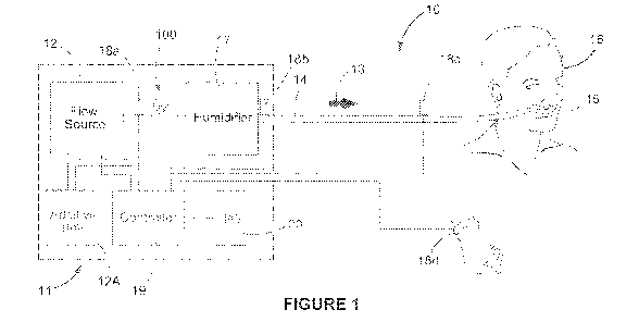
[0158] In this specification, "high flow" means, without limitation, any
gas flow with
a flow rate that is higher than usual/normal, such as higher than the normal
inspiration
flow rate of a healthy patient. Alternatively, or additionally, it can be
higher than some
other threshold flow rate that is relevant to the context ¨ for example, where
providing
a gas flow to a patient at a flow rate to meet inspiratory demand, that flow
rate might
be deemed "high flow" as it is higher than a nominal flow rate that might have
otherwise been provided. "High flow" is therefore context dependent, and what
constitutes "high flow" depends on many factors such as the health state of
the
patient, type of procedure/therapy/support being provided, the nature of the
patient
(big, small, adult, child) and the like. Those skilled in the art would
appreciate from
CA 03204689 2023-06-07
WO 2022/130306
PCT/IB2021/061898
23
context what constitutes "high flow". It is a magnitude of flow rate that is
over and
above a flow rate that might otherwise be provided.
[0159] But, without limitation, some indicative values of high flow can
be as
follows.
[0160] In some configurations, delivery of gases to a patient at a flow
rate of
greater than or equal to about 5 or 10 litres per minute (5 or 10 LPM or
L/min).
[0161] In some configurations, delivery of gases to a patient at a flow
rate of about
5 or 10 LPM to about 150 LPM, or about 15 LPM to about 95 LPM, or about 20 LPM
to about 90 LPM, or about 25 LPM to about 85 LPM, or about 30 LPM to about 80
LPM, or about 35 LPM to about 75 LPM, or about 40 LPM to about 70 LPM, or
about
45 LPM to about 65 LPM, or about 50 LPM to about 60 LPM. For example,
according
to various embodiments and configurations described herein, a flow rate of
gases
supplied or provided to an interface via a system or from a flow source or
flow
modulator, may comprise, but is not limited to, flows of at least about 5, 10,
20, 30,
40, 50, 60, 70, 80, 90, 100, 110, 120, 130, 140, 150 LPM, or more, and useful
ranges
may be selected to be any of these values (for example, about 20 LPM to about
90
LPM, about 40 LPM to about 70 LPM, about 40 LPM to about 80 LPM, about 50 LPM
to about 80 LPM, about 60 LPM to about 80 LPM, about 70 LPM to about 100 LPM,
about 70 LPM to about 80 LPM).
[0162] In "high flow" the gas delivered will be chosen depending on for
example
the intended use of a therapy. Gases delivered may comprise a percentage of
oxygen. In some configurations, the percentage of oxygen in the gases
delivered may
be about 15% to about 100%, 20% to about 100%, or about 30% to about 100%, or
about 40% to about 100%, or about 50% to about 100%, or about 60% to about
100%, or about 70% to about 100%, or about 80% to about 100%, or about 90% to
about 100%, or about 100%, or 100%.
[0163] In some embodiments, gases delivered may comprise a percentage
of
carbon dioxide. In some configurations, the percentage of carbon dioxide in
the gases
delivered may be more than 0%, about 0.3% to about 100%, about 1% to about
100%, about 5% to about 100%, about 10% to about 100%, about 20% to about
100%, or about 30% to about 100%, or about 40% to about 100%, or about 50% to
CA 03204689 2023-06-07
WO 2022/130306
PCT/IB2021/061898
24
about 100%, or about 60% to about 100%, or about 70% to about 100%, or about
80% to about 100%, or about 90% to about 100%, or about 100%, or 100%.
[0164] Flow rates for "High flow" for premature/infants/paediatrics
(with body mass
in the range of about 1 to about 30 kg) can be different. The flow rate can be
set to
0.4-8 L/min/kg with a minimum of about 0.5 L/min and a maximum of about 70
L/min.
For patients under 2 kg maximum flow may be set to 8 L/min.
[0165] High flow has been found effective in meeting or exceeding the
patient's
normal inspiratory flow, to increase oxygenation of the patient and/or reduce
the work
of breathing. Additionally, high flow therapy may generate a flushing effect
in the
nasopharynx such that the anatomical dead space of the upper airways is
flushed by
the high incoming gas flows. This creates a reservoir of fresh gas available
for each
and every breath, while minimising re-breathing of carbon dioxide, nitrogen,
etc.
[0166] By example, a high flow respiratory system 10 is described with
reference
to Figure 1. High flow may be used as a means to promote gas exchange and/or
respiratory support through the delivery of oxygen and/or other gases, and
through
the removal of CO2 from the patient's airways. High flow may be particularly
useful
prior to, during or after a medical and/or anaesthetic procedure.
[0167] When used prior to a medical procedure, high gas flow can pre-
load the
patient with oxygen so that their blood oxygen saturation level and volume of
oxygen
in the lungs is higher to provide an oxygen buffer while the patient is in an
apnoeic
phase during the medical procedure.
[0168] A continuous supply of oxygen is important to sustain healthy
respiratory
function during medical procedures (such as during anaesthesia) where
respiratory
function might be compromised (e.g. diminishes or stops). When this supply is
compromised, hypoxia, hypoxaemia, and/or hypercapnia can occur. During medical
procedures such as anaesthesia and/or sedation where the patient is
unconscious or
may become unconscious, the patient is monitored to detect when this happens.
If
oxygen supply and/or CO2 removal is compromised, the clinician stops the
medical
procedure and facilitates oxygen supply and/or CO2 removal. This can be
achieved
for example by manually ventilating the patient for example by bag mask
ventilation,
or by providing a high flow of gases to the patient's airway using a high flow
CA 03204689 2023-06-07
WO 2022/130306
PCT/IB2021/061898
respiratory system. Further, it will be appreciated that a mask that is used
for
sedation/ventilation (not necessarily limited to a bag mask) may also be used
for pre-
oxygenation and also for monitoring patient parameters such as end tidal CO2,
etc.
[0169] Further advantages of high gas flow can include that the high
gas flow
5 increases pressure in the airways of the patient, thereby providing
pressure support
that opens airways, the trachea, lungs/alveolar and bronchioles. The opening
of these
structures enhances oxygenation, and to some extent assists in removal of CO2.
[0170] When humidified, the high gas flow can also prevent airways from
drying
out, mitigating mucociliary damage, and reducing risk of laryngospasms and
risks
10 associated with airway drying such as nose bleeding, aspiration (as a
result of nose
bleeding), and airway obstruction, swelling and bleeding. Another advantage of
high
gas flow is that the flow can clear smoke created during surgery in the air
passages.
For example, smoke can be created by lasers and/or cauterizing devices.
[0171] With reference to Figure 1, the system 10 may comprise an
integrated or
15 separate component-based arrangement, generally shown in the dotted box
11 in
Figure 1. In some configurations, the system 10 could comprise a modular
arrangement of components. The system 10 may include a flow source 12, such as
an in-wall source of oxygen, an oxygen tank, a blower, a flow therapy
apparatus, or
any other source of oxygen or other gas or combination thereof. In some
20 embodiments, the flow source 12 comprises a flow modulator and in some
embodiments, the flow modulator comprises a flow generator such as a blower,
bellow, and/or pistons. In some embodiments, the flow modulator comprises a
flow
generator and a proportional valve which may function to control oxygen
concentration in a flow of blended gas such as air (preferably filtered air)
and oxygen
25 which is delivered to the patient. In some embodiments, the flow
modulator comprises
a proportional valve, and in such embodiments, the flow modulator may not
comprise
a flow generator. An example of a system comprising a flow generator and
proportional valve in this context is described in relation to Figures 7 and
8. In other
embodiments, the flow source 12 need not comprise a flow generator and in such
embodiments, the flow source 12 may comprise an in-wall gas source and/or a
blended gas or other gas supply. In some embodiments, the flow source 12 may
CA 03204689 2023-06-07
WO 2022/130306
PCT/IB2021/061898
26
comprise a compressed gas source (e.g. an in-wall gas source, an oxygen tank
supply, etc.) and a blower.
[0172] In some embodiments, the flow source 12 comprises or is part of
an
anaesthesia machine. The system 10 may also comprise an additive gas source
12A,
comprising one or more other gases that can be combined with gases from the
flow
source 12. The flow source 12 can provide a flow of gas 13 that can be
delivered to a
patient 16 via a delivery conduit 14, and patient interface 15 (such as a
nasal
cannula). The flow of gas 13 may deliver a high flow to the patient, in the
context
described in the foregoing. A controller 19 controls the flow source 12 and
additive
gas source 12A through valves or the like to control flow and other
characteristics
such as any one or more of flow rate, pressure, composition, concentration,
volume of
the flow of gas 13. A humidifier 17 is also optionally provided, which can
humidify the
gas and/or control the temperature of the gas, for example under the control
of the
controller 19. One or more sensors 18a, 18b, 18c, 18d, such as flow, oxygen,
pressure, humidity, temperature or other sensors can be placed throughout the
system and/or at, on or near the patient 16. The sensors can include a pulse
oximeter
18d on the patient for determining the oxygen concentration in the blood.
[0173] The controller 19 may be operatively coupled with one or more
components of system 10 by various means including wired or wireless coupling.
For
example, controller 19 may be operatively coupled with one or more of the flow
source 12, the additive gas source 12A, humidifier 17 and sensors 18a-18d and
input/output (I/O) interface 20. By way of example, the controller 19 may be
provided
on or in a high flow apparatus, a separate component and/or incorporated into
or
utilised with another device such as an anaesthesia machine or a ventilator,
or it may
comprise part of system 10 and communicate with one or more separate
controllers
controlling operation of separate components used with system 10 for the
provision of
respiratory support to the patient. The controller may comprise a
microcontroller, a
PID (proportional¨integral¨derivative) controller or a variation of a PID
controller
where the proportional, integral and derivative elements of the controller can
be
turned on or off as needed (such as P, PI or I controllers), or some other
architecture,
configured to operate by an algorithm that is stored in a memory in
communication
with the controller to direct the operation of controllable components of the
respiratory
system. The controller 19 may thus control the flow source 12 and other
components
CA 03204689 2023-06-07
WO 2022/130306
PCT/IB2021/061898
27
of or used with system 10 to provide the delivered flow of gas to the patient
with
certain characteristics such as a desired flow rate, pressure, composition
(where
more than one gas is being provided), volume and/or other parameters based on
feedback from one or more sensors 18a-18d. The controller 19 can also control
any
other suitable parameters of the flow source to meet oxygenation, airway
pressure
and/or flow requirements of the patient and/or system pressure and/or flow
requirements of the system (for example pre-determined or set by a user
through
interface 20). The controller 19 can also control the humidifier 17 and this
control may
be based on feedback from one or more of the sensors 18a-18d. Using input from
the
sensors, the controller may determine operational changes required to meet
oxygenation requirements and alter control parameters of the flow source 12
and/or
humidifier 17 and/or other additive gas source 12A and/or other components of
the
system as required.
[0174] An input/output (I/O) interface 20 (such as a display and/or
input device)
may be provided. The interface 20 enables information and inputs (such as the
required patient respiratory support parameters) to be received from a user
(e.g.
clinician or patient) that can be used for determining oxygenation, pressure,
flow
requirements and/or other system settings used in the control of one or more
of the
flow source 12, additive gas source 12A and other components of the system 10,
to
achieve a flow of gas 13 with the characteristics necessary to provide the
required
respiratory support. In some embodiments, the system may be without a
controller
and/or I/O interface. A medical professional such as a nurse or technician may
provide the necessary control function.
[0175] As noted above, the high gas flow (optionally humidified) may be
delivered
to the patient 16 via a delivery conduit 14 and the patient interface 15 or
'interface',
such as a cannula, mask, nasal interface, oral device or combination thereof.
In some
embodiments, the high gas flow (optionally humidified) may be delivered to the
patient
16 for surgical uses, e.g. surgical insufflation. In these embodiments, the
'interface'
could be a surgical cannula, trocar, or other suitable interface. The patient
interface
may seal, substantially seal, partially seal, be non-sealing, substantially
non-sealing,
or partially non-sealing with a patient's airways. A nasal interface as used
herein is a
device such as a cannula, a nasal mask, nasal pillows, or other type of nasal
device
CA 03204689 2023-06-07
WO 2022/130306
PCT/IB2021/061898
28
or combinations thereof configured to direct a flow of gas into one or both
nares of the
patient.
[0176] A nasal interface can also be used in combination with a face
mask 300, as
shown in Figure 2b, or oral device (such as a tube inserted into the mouth)
and/or a
mask or oral device (such as a tube inserted into the mouth) that can be
detached
and/or attached to the nasal interface.
[0177] A nasal cannula is a nasal interface that may include one or
more prongs
that are configured to be inserted into a patient's nasal passages. A mask
refers to an
interface that covers a patient's nasal passages and/or mouth and can also
include
devices in which portions of the mask that cover the patient's mouth are
removable. A
mask also refers to a nasal interface that includes nasal pillows that create
a
substantial seal with the patient's nostrils.
[0178] Figures 2a and 2b show examples of a patient 16 wearing a
patient
interface 200, for example the nasal cannula 15 of the respiratory system 10
of Figure
1, with a collapsible breathing conduit portion. The patient depicted is an
adult.
However, the patient may be an infant, child or adolescent.
[0179] The patient interface 200 comprises a first gas (delivery)
conduit 202. The
first gas conduit 202 is adapted to receive gases from the respiratory system
10 of
Figure 1 (for example, via the conduit 14 shown in Figure 1) and direct the
gases to
the patient 16. The first gas conduit 202 may comprise a reinforcement element
203
adapted to strengthen and/or add rigidity to the first gas conduit to prevent
deformation or collapse of the first gas conduit 202 arising due to the
application of
forces against the first gas conduit 202. The reinforcement element 203 may
include a
number of structures, including but not limited to plastic or metallic
reinforcing beads
that lie in or on the wall of the first conduit lumen 202.
[0180] The patient interface 200 may comprise a gases delivery side arm
in fluid
communication with the first gas conduit 202. The first gas conduit 202 is in
pneumatic communication with a flow manifold 206 which is provided at an end
of the
gases delivery side arm. The flow manifold 206 receives gases from the first
gas
conduit 202 and provides passage to one or more nasal delivery elements 208
(e.g.
nasal prongs) extending from the manifold. The one or more nasal delivery
elements
CA 03204689 2023-06-07
WO 2022/130306
PCT/IB2021/061898
29
208 extend outwardly from the flow manifold 206. The one or more nasal
delivery
elements 208 are adapted to be non-sealingly positioned in one or more nares
of the
patient 16. First patient interface 200 is accordingly a non-sealing patient
interface. As
shown, the patient interface 200 comprises two nasal prongs 208 adapted to be
positioned with one in each of the patient's nares. Each nasal prong 208 may
be
shaped or angled such that it extends inwardly towards a septum of the
patient's
nose. Alternatively, the first patient interface 200 may be a sealing nasal
interface.
[0181] In the embodiment shown in Figures 2a and 2b, the flow manifold
206
receives flow from one lateral side of the flow manifold 206 (e.g. with
respect to an
imaginary vertical plane bisecting the face of the patient P) and provides a
passage
for flow through to the manifold to each of the nasal prongs 208. In some
embodiments a conduit may extend from a single side of the manifold, for
example
from the left-hand side or from the right-hand side of the manifold. In some
situations,
providing the conduit on the left-hand side of the patient interface may be
preferred
for access by a clinician, for example for intubation. Alternatively, a
conduit extending
from the right-hand side may be preferred, for example in procedures such as
endoscopies where the patient is typically lying on his or her left-hand side.
In other
configurations, the patient interface 200 may comprise greater (for example,
three or
four) or fewer (for example, one) nasal delivery elements 208. In other
configurations,
each of the nasal delivery elements 208 can have different properties. For
example,
one of a pair of nasal delivery elements 208 can be relatively long and the
other nasal
delivery elements 208 can be relatively short.
[0182] In some configurations, the flow manifold 206 may be configured
to receive
flow from two lateral sides of the flow manifold 206 (e.g. from a 'left' and
'right' of the
flow manifold 206 instead of just the patient's right-hand side of the flow
manifold 206
as seen in Figures 2a and 2b). In some such configurations, multiple gas
conduits
may be used to provide for pneumatic communication between the flow manifold
206
and the respiratory system 10. For example, the patient interface may comprise
dual
conduits, the first gas conduit 202 extending from a first side of the
interface (in the
illustrated example the right-hand side of the patient) and a second gas
conduit (not
shown) extending from a second opposite side of the interface. In some
configurations, the flow manifold 206 may be configured to receive flow from a
non-
CA 03204689 2023-06-07
WO 2022/130306
PCT/IB2021/061898
lateral side of the flow manifold 206 (e.g. from a 'bottom' or 'top' of the
flow manifold
206 or both) or from a front face of the flow manifold 206, opposite the
patient 16.
[0183] The patient interface 200 may further comprise mounts and/or
supports,
e.g., cheek supports 210, for attaching and/or supporting the gas conduit 202
or
5 conduits on the patient's face. Alternatively, or additionally, the
patient interface 200
may be held in place via one or more head straps or headgear (not shown).
[0184] The first gas conduit 202 of the patient interface 200 comprises
a first
portion 204 configured to transition from a first configuration in which a
first level of
gases is able to pass through the first portion 204 to a second configuration
in which a
10 second level of gases is able to pass through the first portion 204.
[0185] Figure 2b shows the patient 16 wearing the patient interface 200
comprising two nasal prongs 208 simultaneously underneath a face mask assembly
300 (a second patient interface). In this arrangement, face mask assembly 300
is
placed upon the patient interface 200 which is worn by patient 16. Figure 2b
15 schematically shows the face mask assembly 300 as a transparent
structure in order
to illustrate the patient interface 200 under it. The first patient interface
200 may be
used with a first respiratory support system 10 and the face mask assembly
(second
patient interface) 300 may be used together with a second respiratory support
system
(not shown). In some configurations, the first and second respiratory support
systems
20 are the same system and/or the first and second respiratory support
systems
comprise a common flow source despite the modes of respiratory support being
provided by the first and second respiratory support systems being different.
In other
configurations, the first and second respiratory support systems are separate
systems.
25 [0186] The configuration shown in Figure 2b may be beneficial in
the provision of
selective delivery of separate therapies or modes of support to a patient
using
different patient interfaces, and/or in stopping or ceasing the delivery of a
therapy
from an interface and/or allowing gases provided by an interface to be
sampled. For
example, the configuration may find particular application in emergency
resuscitation,
30 .. around intubation of a patient receiving high flow therapy, ear, nose,
and throat (ENT)
CA 03204689 2023-06-07
WO 2022/130306
PCT/IB2021/061898
31
surgery, in assisting with conditioning of a patient in a pre-operative state
prior to
administration of anaesthetics, and during post-extubation and recovery.
[0187] The face mask assembly 300 may be used as or with a second
respiratory
support system and/or to deliver one or more substances other than a substance
delivered by the cannula 200. For example, for delivery of anaesthetic agents
and/or
oxygen, to the patient, or for delivery of the same substance as the first
patient
interface 200 but at different flow and/or pressure levels. Alternatively, the
face mask
assembly 300 may be used to reduce or stop the delivery of therapy from a
first
respiratory support system through the first patient interface 200. In some
embodiments, the face mask assembly 300 may also be adapted to measure
respiratory gases, for example exhaled carbon dioxide from the patient, the
measurements of which may otherwise be affected by flow from the patient
interface
200 of the first respiratory support system.
[0188] The configuration shown in Figure 2b allows for the alternation
between the
two different respiratory support systems. Additionally, this configuration
may allow
the first patient interface 200 to be left on the patient throughout a medical
procedure
and/or into recovery (whether or not the patient continues to receive therapy
through
the patient interface 200 throughout the procedure) without interfering with
other
clinical practices.
[0189] In the embodiment shown, the face mask assembly 300 comprises a full-
face mask 302 configured to cover both the patient's nose and mouth. In other
configurations, the face mask assembly 300 may comprise a nasal mask which is
placed over the patient interface 200 to cover only the patient's nasal
region.
[0190] As shown, the face mask 302 comprises a seal region 304 adapted
to seal
against the patient's face. The face mask assembly 300 is connected to a
second gas
source, for example via a filter element 350, which supplies the one or more
other
gases to the patient via the face mask. In some configurations, the second gas
source
is different from the source supplying gas (for example a supplementary gas
source
or flow generator) to the patient interface 200. In some configurations, the
second gas
source is the same as the source supplying gas to the patient interface 200.
CA 03204689 2023-06-07
WO 2022/130306
PCT/IB2021/061898
32
[0191] In some embodiments, the face mask assembly 300 is connected to
a
second flow source that is or comprises a separate gas source or a separate
respiratory support system configured to provide respiratory support separate
from
any flow source, or respiratory support system delivering a flow of gas to the
first
patient interface 200. For example, the separate respiratory support system
can be a
ventilator or a CPAP or a high flow therapy device or a manual resuscitator
(for
example a hand-held face mask with bag). Alternatively or additionally, the
face mask
assembly 300 may be connected to a device for measuring a characteristic of
respiratory gases.
[0192] Alternatively, the separate respiratory support system may be or
comprise
an anaesthetic device and/or the second gas source may comprise an anaesthetic
gas, or air, or oxygen, or a combination of gases, for delivery via the face
mask 302.
[0193] The configuration shown in Figure 2b allows for the delivery of
gas from
multiple sources via at least two different respiratory support modes, and
further
allows a doctor, clinician or medical professional to quickly and easily
change the type
of respiratory support mode.
[0194] In one particular application, a patient undergoing an
anaesthetic
procedure may undergo pre-oxygenation by delivering a high flow of oxygen or
humidified gases or mixture of both, for example via a nasal cannula, when the
patient is still spontaneously breathing and before the administration of
anaesthetic
agents. Pre-oxygenation increases the patient's oxygen reservoir prior to the
anaesthetic procedure. The term "anaesthetic procedure" may refer, without
limitation,
to general anaesthesia, procedural sedation and regional/local anaesthesia. In
some
circumstances, anaesthetists managing the anaesthetic procedure of a patient
may
.. want to switch between delivery of gas flow from one patient interface (for
example a
nasal cannula 200) and delivery of gas flow from another patient interface,
such as
via a face mask 300.
[0195] Anaesthetists also use a mask with a bag to oxygenate a patient,
and in
some instances find it more beneficial to use a bag mask if a patient's vital
signs
begin to drop for example to deliver more pressure to support the patient's
airways, or
to have greater manual control over the variation in delivered pressure. In
some
CA 03204689 2023-06-07
WO 2022/130306
PCT/IB2021/061898
33
situations, a medical professional may wish to switch between different
respiratory
systems or support modes. In a first mode, respiratory support may be provided
by
first respiratory support system (for example via the patient interface 200)
and in a
second mode respiratory support may be provided by a second respiratory
support
system (for example via the face mask assembly 300), with the support from the
first
system reduced or stopped. For example, it may be desirable to stop high flow
from a
first patient interface 200 when delivering anaesthetic agents through the
face mask
assembly 300 because a high flow from interface 200 may modify the expected
behaviour of the anaesthetic circuit provided by the face mask 300 (which is
typically
a sealed circuit) and may dilute anaesthetic agents delivered by face mask
assembly
300. Thus, it may be advantageous to be able to stop the additional flow from
the first
respiratory system or substantially reduce it.
[0196] In some configurations, the switching between two respiratory
support
modes or subsystems may be facilitated by a structure of the first gas conduit
202,
which has first portion 204 configured to transition between a first
configuration in
which a first level of gases is able to pass through the first portion 204 and
a second
configuration in which a second level of gases is able to pass through the
first portion
204.
[0197] In some configurations, the first portion 204 is configured to
be more
collapsible or otherwise better adapted for changing the flow of gas through
the first
portion 204 (to reduce the flow of gas through the conduit and to the patient)
than
other portions of the conduit 202, and/or allowing a seal of a mask to seal
over the top
of the conduit. In other configurations the entire conduit 202 may be
configured to be
collapsible or otherwise better adapted for changing the flow of gas through
conduit
202. In some configurations a vent arrangement may be provided upstream of a
collapsible portion, to vent gases from the conduit upstream of the
collapsible portion
to atmosphere.
[0198] In some embodiments, the first configuration is a fully or
substantially open
condition, and the second configuration is a fully or substantially closed
condition.
.. That is, the conduit 202 is configured to be more collapsible, deformable
or otherwise
adapted to fully or substantially close off the flow at the first portion 204
than at other
portions of the conduit 202, when in the second configuration. It will be
understood
CA 03204689 2023-06-07
WO 2022/130306
PCT/IB2021/061898
34
that there may be one or more intermediate conditions between the first and
second
configurations, where these one or more intermediate conditions may be less
open
(or more closed) than the fully or substantially open condition (first
configuration) but
more open (or less closed) than the fully or substantially closed condition
(second
configuration).
[0199] Figures 3a and 3b provide schematic illustrations of the first
and second
configurations wherein Figure 3a shows the first configuration (substantially
open)
and Figure 3b shows the first portion 204 in the second configuration
(substantially
closed) by application of the seal 304 of face mask 302 over the first portion
204. In
some embodiments, the first portion 204 (i.e. the more collapsible or
deformable
section) of the first gas conduit 202 should be of a length that is greater
than a width
of a section of a seal 304 of the face mask 302 that bears over the first
portion 204 of
the first gas conduit 202. This ensures the seal of the face mask 302 does not
bear
over a non-collapsible section of the first gas conduit 202. For example, the
first
portion 204 may extend from a distance of 35mm or less from the centre of a
user's
nose to at least 50mm from the centre of a user's nose. The first portion 204
may
have a length of at least about 5mm, about lmm to about 30mm in length, or
about
5mm to about 15mm in length, or about 10mm in length. In some embodiments the
length of the first portion may be at least lmm, 2mm, 3mm, 4mm, 5mm, 6mm, 7mm,
8mm, 9mm, 10mm, 11mm, 12mm, 13mm, 14mm, 15mm, 20mm, 25mm, 30mm,
35mm, 40mm, 45mm, 50mm or greater.
[0200] The first portion 204 may progress between the first and second
configurations based on a relative level of force applied to a wall of the
first portion
204. For example, as shown in Figures 2 and 3, the force may be applied by the
seal
304 of face mask 302. In this example, first portion 204 is configured to be
positioned
under the seal 304 of the face mask 302.
[0201] Alternatively, the force may be applied to first portion 204 by
other means,
e.g., clamps (not shown), or alternatively a medical practitioner may compress
the
conduit by pressing on the conduit wall with a finger or thumb.
[0202] In some embodiments, the seal of the face mask acting on the first
portion
204 of the gas conduit 202 causes the first portion 204 to form a seal or at
least a
CA 03204689 2023-06-07
WO 2022/130306
PCT/IB2021/061898
partial seal between the nasal outlets of the first patient interface 200 and
the flow
source 12. Additionally, the seal of the face mask forms a seal or at least a
partial
seal over the first portion 204 of the gas conduit 202.
[0203] Switching between respiratory support therapies may therefore be
5 achieved simply by applying a mask to the patient's face so that the seal
of the mask
collapses (partially or completely) the first portion 204 of the gas conduit
202
supplying the first interface 200 to reduce or stop the therapy supplied by
the first
interface 200. This also provides a seal between the face mask 300 and the
external
surface of the first portion 204 of the conduit 202 such that respiratory
support or
10 therapy can be provided by the face mask 300 where the respiratory
support or
therapy provided by the first patient interface 200 can be reduced or shut
off. The
patient interface 200 with a collapsible conduit portion 204 allows a user,
e.g. an
anaesthetist or a nurse or a clinician, to use a face mask assembly 300 over
the
patient interface 200 to select and control delivery of gases from multiple
respiratory
15 support systems to provide different therapies or modes of support. The
first patient
interface 200 may be structured to function in a manner that prevents the
delivery of
high flow and other respiratory therapy or anaesthetic agents through the
patient
interface 200 when the first portion 204 is in a second configuration. In some
embodiments removal of the face mask assembly 300 from the patient's face
allows
20 the first portion 204 to return to its first configuration so that
respiratory support or
therapy supplied by the first patient interface 200 can recommence or return
to
operating in the conditions present prior to the change in configuration.
[0204] Embodiments of the present disclosure provide for improved
control of a
flow of respiratory gases provided to a patient. In some embodiments, the
respiratory
25 support system includes a pressure relief valve or device. The system 10
may include
such a pressure relief or regulating device, or pressure limiting device 100
(e.g. a
pressure relief valve or PRV). This pressure limiting device 100 may be a
valve
having features described in W02018/033863, the entirety of which is
incorporated by
reference herein. In some embodiments, the respiratory system does not
include, or
30 excludes a pressure relief valve or device. In some embodiments, the
respiratory
system does not include, or excludes a flow compensated pressure relief valve
or
device, for example, a flow compensated pressure relief valve having features
as
described in W02018/033863.
CA 03204689 2023-06-07
WO 2022/130306
PCT/IB2021/061898
36
[0205] Pressure relief and pressure control are particularly desirable
for use in a
respiratory support system such as a high flow system 10 comprising a non-
sealing
patient interface (such as a nasal cannula in first patient interface 200), to
provide an
upper limit on pressures that may be generated downstream from the flow source
12
which in turn can impact patient airway pressure (also referred to as patient
pressure). Importantly, the upper pressure limit may be configured to provide
a safety
threshold, to ensure patient pressure safety, and/or to prevent damage to
tubes, fluid
connections, or other components in the system 10 due to over-pressure.
Similarly, a
pressure relief or regulating device 100 may be used in a sealed system, such
as
CPAP (continuous positive airway pressure), BiPAP (bilevel positive airway
pressure)
and/or Bubble CPAP systems to regulate the pressure provided to the patient.
[0206] A respiratory system 22 for providing a flow of respiratory
gases to a
patient is shown in Figures 4 to 8 according to different embodiments of the
present
disclosure.
[0207] Figure 4 shows a respiratory system 22 comprising a controller 24
and a
flow source 12 which may comprise a flow modulator configured to be controlled
by
the controller 24 to modulate a flow of respiratory gases to a patient 16. The
controller
may be configured to receive an input of a flow rate and a pressure of the
flow of
respiratory gases in the system, and be configured to control the flow source
to
.. provide the flow of respiratory gases at a target flow rate to a patient
and control the
flow modulator to modulate the flow of respiratory gases to a target pressure
when
the pressure of the flow of respiratory gases in the system meets or exceeds a
pressure threshold value corresponding to that target flow rate. In some
embodiments, the target pressure comprises the pressure threshold value
.. corresponding to the target flow rate or a pressure threshold value
corresponding to a
flow rate less than the target flow rate. The pressure threshold value
corresponding to
the target flow rate may be determined by the controller e.g. using a function
stored in
a memory component of or operatively coupled with the controller as described
elsewhere herein. A target pressure or pressure threshold may be defined as an
absolute pressure value or a gauge pressure value.
[0208] As mentioned, the flow source 12 may comprise a flow generator,
such as
a blower, configured to be controlled by the controller 24 to generate the
flow of
CA 03204689 2023-06-07
WO 2022/130306
PCT/IB2021/061898
37
respiratory gases. Alternatively, or additionally, the flow source 12 may
comprise a
proportional valve configured to be controlled by the controller 24 to
modulate the flow
of respiratory gases from a gas source, or the flow source 12 may comprise a
combination of a flow generator and a proportional valve.
[0209] Typically, the system 22 further comprises one or more sensors 28
configured to determine characteristics of the respiratory system, for example
characteristics of the flow of respiratory gases in the respiratory system
and/or being
provided to the patient. The system 10 can use ultrasonic transducer(s), flow
rate
sensor(s) such as thermistor flow sensor(s), pressure sensor(s), temperature
sensor(s), humidity sensor(s), or other sensors, in communication with the
controller
24, to monitor characteristics of the system and/or operate the system 22 in a
manner
that provides suitable respiratory support. Such characteristics can include
gases
concentration, flow rate, pressure, temperature, humidity, or other
characteristics. The
sensors 28, such as pressure, temperature, humidity, and/or flow rate sensors,
can
be placed in various locations of the system 22 such as for example, inside a
main
housing containing components of system 22, the patient conduit 12, and/or the
patient interface 200. The controller 24 can receive signals from the sensors
28
providing controller inputs used in determining control of one or more
components of
the respiratory support system 22 in a manner that provides suitable
respiratory
support. For example, the controller 24 may use signals from one or more of
the
sensors 28 to determine a suitable target temperature, humidity, flow rate,
and/or
oxygen concentration of the gases flow, or suitable pressures that may be
generated
downstream from the flow source 12 within the system. Providing suitable
respiratory
support can include meeting a patient's inspiratory demand. The suitable
respiratory
support flow rates, such as a high flow rate, and/or a flow rate meeting or
exceeding
the patient's inspiratory demand, are explained elsewhere herein.
[0210] In some embodiments, the sensors comprise flow rate sensors
(such as
e.g. ultrasonic, thermal based or other suitable flow rate sensors) configured
to sense
flow rate of the flow of gases provided to the patient 16, and the sensed flow
rate is
used by the controller 24 to determine a safe upper pressure limit for
operation of the
system 22 at the sensed flow rate. The controller 24 can then control
operation of one
or more components (e.g. actuators) of system 22 (or transmit a control signal
to one
or more components of the system) such as the flow source 12 to e.g. modify
blower
CA 03204689 2023-06-07
WO 2022/130306
PCT/IB2021/061898
38
speed, so as to achieve a target flow rate stored in the controller, or a
memory in
operative communication with the controller or any other component of the
system.
The target flow rate may be a flow rate set point entered by a user of the
system
through I/O interface 20 or it may be determined or pre-programmed into the
.. controller or associated memory/components. Modifying the flow rate may
involve an
increase or decrease in blower speed (and/or an increase or decrease in
aperture
size of a proportional valve), to achieve an increase or decrease in flow
rate,
respectively.
[0211] In some embodiments, when the system begins operation from an
'off or
dormant state, the controller is configured to monitor the flow rate of the
flow of
respiratory gases in the system and is configured to control the flow
modulator to
modulate the flow of respiratory gases to achieve the target flow rate.
Ideally, the
target flow rate changes over time to increase from a current value to a flow
rate set
point. The controller may also be configured to monitor the flow rate of the
flow of
respiratory gases to a new target flow rate in other circumstances, such as
when a
user changes the flow rate set point to which the system operates.
[0212] The controller 24 may receive inputs from one or more pressure
sensors.
The controller can measure or infer the pressure delivered to the patient from
the
pressure sensor inputs. The pressure sensors are located downstream of the
flow
source 12. For example, a pressure sensor can be located at or near the
patient
interface 200. A pressure sensor can also be located directly after the flow
source.
The pressure delivered to the patient's airways (patient pressure) can be
determined
by the controller calculating the difference between the ambient pressure and
the
absolute pressure downstream of the flow source. The patient pressure can be
estimated by measuring the pressure in the main device housing downstream of
the
flow generator and calculating the pressure drop along the delivery conduit
202. The
pressure sensor(s) can also be located at other locations in the pneumatic
circuit
downstream of the flow source 12gases flow. The pressure sensor(s) can include
one
or more gauge pressure sensors, or alternatively one or more absolute pressure
.. sensors. The gauge pressure sensor(s) can directly measure a difference
between
the absolute pressure downstream of the flow generator and the ambient
pressure. In
systems having two absolute pressure sensors, one sensor can be located
downstream of the flow source to measure the absolute pressure downstream of
the
CA 03204689 2023-06-07
WO 2022/130306
PCT/IB2021/061898
39
flow source and the other sensor can be located in a different location to
measure the
ambient pressure. The controller can determine the pressure delivered to the
patient
by determining the differences between the pressure measurements made by the
two
absolute pressure sensors.
[0213] The controller 24, in various embodiments, is configured to receive
one or
more signals directly from one or more pressure sensors, or through manual
inputs
provided to a user interface which is in operative communication with the
controller, or
derived values, which are indicative of system pressure in the pneumatic
circuit
downstream of the flow source 12 through which the flow of respiratory gases
in the
respiratory system 22 are delivered to patient 16. The controller 24 may
convert the
received signals to pressure values, and the controller may compare these
values
with pressure threshold values for corresponding flow rates as stored by the
controller
or a memory device or module in operative communication with the controller.
Since
the controller is required to know the flow rate of gases in the pneumatic
circuit in
.. order to ascertain if the system pressure meets or exceeds the pressure
threshold for
corresponding flow rates, the controller may also receive one or more signals
directly
from one or more flow rate sensors, or the controller may obtain flow values
through
manual inputs provided to a user interface in operative communication with the
controller, or it may derive flow values e.g. by knowing the resistance to
flow in the
.. pneumatic components of the system 22, and calculating the flow from e.g.
blower
speed in the flow source 12.
[0214] Controller 24 may determine the system pressure continuously, or
intermittently and there may be benefits associated with each. For example,
continuous determination of system pressure provides for maximum
responsiveness
.. in terms of how fast the controller can detect a change in which system
pressure
meets or exceeds (or falls below) the pressure threshold for a corresponding
flow
rate, and respond quickly by controlling the flow source 12 e.g. to reduce
blower
speed (which may in turn reduce the flow of respiratory gases) in response to
the
pressure meeting or exceeding the pressure threshold values for the
corresponding
flow rates, and to control the flow source 12 to modulate the flow of
respiratory gases
in response to the pressure not meeting or exceeding the pressure threshold
values
for the corresponding flow rates. Alternatively, the controller 24 may sense
or receive
pressure inputs intermittently which provides for more economical operation,
however
CA 03204689 2023-06-07
WO 2022/130306
PCT/IB2021/061898
the system may experience delays in responsiveness since the system pressure
may
change sometime before the controller receives a pressure input, and so the
modulating and/or control of the flow source 12 will not be as responsive.
[0215] The pressure threshold values for corresponding flow rates may
be stored
5 by a memory component of the controller 24 or a memory device or
component
external to and in operative communication with controller 24. The
relationship
between the pressure threshold values and the corresponding flow rates may be
stored as one or more of a function, a curve, a lookup table, or a
mathematical model
or algorithm used by the controller to determine the particular pressure
threshold
10 value for a corresponding flow rate. In some embodiments, the
relationship between
the pressure threshold values and the corresponding flow rates as utilised by
the
controller 24 can be represented graphically and examples are shown in Figures
9 to
14.
[0216] Figure 5 shows another embodiment of a respiratory system 22
comprising
15 a controller 24 and a flow source 12 configured to be controlled by the
controller 24 to
modulate a flow of respiratory gases to a patient 16 via a patient interface
200, in fluid
communication with the flow source 12 and configured to deliver the flow of
respiratory gases to the patient 16. The respiratory system 22 also comprises
one or
more sensors 28 configured to determine system pressure downstream of the flow
20 source 12, and/or the flow rate of the flow of respiratory gases in the
respiratory
support system providing the gases to the patient.
[0217] The patient interface 200 receives a flow of respiratory gases
from the flow
source 12 via a conduit 202. Conduit 202 comprises a first portion 204
configured to
operate in at least a first configuration and a second configuration.
25 [0218] The controller 24 in the embodiment shown in Figure 5 may
be configured
to receive inputs indicative of pressure and/or flow rate of the flow of
respiratory
gases in the respiratory support system 22 from the sensors 28, compare the
sensed
pressure with a pressure threshold, and control the flow source 12 to provide
a first
modulation of the flow of respiratory gases in response to the pressure
meeting or
30 exceeding the pressure threshold, and control the flow modulator 26 to
provide a
CA 03204689 2023-06-07
WO 2022/130306
PCT/IB2021/061898
41
second modulation of the flow of respiratory gases in response to the pressure
not
meeting or not exceeding the pressure threshold.
[0219] As mentioned, in some embodiments, the second modulation is
different
from the first modulation and the first modulation comprises maintaining the
system
pressure downstream of the flow source at a target pressure, for example at
the
pressure threshold and/or reducing the system pressure downstream of the flow
source to a target pressure that is below the pressure threshold. The second
modulation may comprise increasing, or decreasing the flow rate of respiratory
gases
to a target flow rate in response to the system pressure downstream of the
flow
source not meeting or not exceeding the pressure threshold.
[0220] A corresponding flow rate may be a flow rate of the flow of
respiratory
gases provided by a flow source, at or along a portion of the pneumatic
circuit of
respiratory system 22 providing the flow of gases to the patient interface
200, at the
patient interface 200 and/or at the patient's airways. As noted in the
foregoing, the
corresponding flow rate may be a flow rate obtained by one or more flow rate
sensors
providing input directly to controller 24, it may be entered by a user
operating a user
interface in operative communication with the controller, or it may be
inferred from
other factors such as e.g. blower speed of the flow source, if the resistance
of the
pneumatic components of the system 22 are known.
[0221] Figure 6 shows a respiratory system 22 according to another
embodiment
of the present disclosure. In this embodiment, the system 22 includes the
controller
24 and the flow source, in the form of a flow modulator or a blower 27,
configured to
be controlled by the controller 24 to generate a flow of respiratory gases to
a patient
16 via a delivery conduit 202. Typically, the controller 24 and the blower 27
are
contained within a common housing 33 although it is contemplated that the
controller
could be located remotely from or in a separate housing to the blower 27 and
other
components of the respiratory support system. In some embodiments, the housing
33
also contains a humidifier (as shown in the embodiment of Figure 1) comprising
a
humidification chamber through which a flow of gases from the blower is passed
to
humidify the gases provided to the patient by increasing the moisture content
and in
some cases, temperature. The humidified gases are then delivered by delivery
conduit 202 (which may comprise a part of the delivery circuit 38 downstream
of the
CA 03204689 2023-06-07
WO 2022/130306
PCT/IB2021/061898
42
humidifier and the patient breathing circuit 40) to the patient interface 200.
The
respiratory support system 22 further includes a patient interface 200
configured to
receive a flow of gases through delivery conduit 202 for delivery to the
patient 16. The
patient interface 200 may comprise one or more nasal elements or a face mask
assembly configured to provide gases to the patent's nare(s) or mouth
respectively or
both. The patient interface 200 receives a flow of respiratory gases from the
blower
27 via a conduit 202. Conduit 202 comprises a collapsible first portion 204
configured
to operate in at least a first configuration and a second configuration as
described
elsewhere in the specification.
[0222] The collapsible portion 204 is configured to operate in a first
configuration
(e.g. un-collapsed or fully or substantially open condition) and collapsible
from the first
configuration to a second configuration (e.g. collapsed or fully or
substantially closed
condition). It will be understood that there may be one or more intermediate
conditions between the first and second configurations, where these one or
more
intermediate conditions may be less open (or more closed) than the fully or
substantially open condition (first configuration) but more open (or less
closed) than
the fully or substantially closed condition (second configuration).. As
mentioned,
controller 24 alters the operation of the flow source when the collapsible
portion 204 is
in the second configuration compared to when the collapsible portion 204 is in
the first
configuration. In some embodiments, this is achieved by modulating (e.g.
reducing)
the speed of the blower 27 which may in turn modulate (e.g. reduce) the flow
of
respiratory gases to a reduced flow rate in the system in response to the
sensed
system pressure meeting or exceeding the pressure threshold values for the
corresponding flow rate of the flow of respiratory gases being provided to the
patient.
In some embodiments, the controller 24 alters the condition (e.g. extent of
opening) of
one or more proportional valves which may in turn modulate (e.g. reduce) the
flow of
respiratory gases to a reduced flow rate in the system in response to the
sensed
system pressure meeting or exceeding the pressure threshold values for the
corresponding flow rates of the flow of respiratory gases being provided to
the patient.
In some embodiments, the controller 24 alters the operation and/or condition
of both a
blower and a proportional valve.
[0223] The respiratory system 22 shown in Figure 6 includes two types
of
sensors: flow rate sensor(s) 32 configured to sense flow rate of the flow of
respiratory
CA 03204689 2023-06-07
WO 2022/130306
PCT/IB2021/061898
43
gases in the respiratory system 22; and pressure sensor(s) 29 configured to
sense
pressure in the respiratory system 22 downstream of the blower 27 including
downstream of an outlet of the housing 33.
[0224] Flow rate sensor(s) 32 and pressure sensor(s) 29 are located
downstream
of the flow modulator, i.e. blower 27. The flow rate sensor(s) 32 and pressure
sensor(s) 29 are configured to sense flow rate and pressure, respectively,
downstream of the flow modulator and in the delivery conduit 202. The
controller 24,
in this embodiment, is configured to receive data indicative of pressure and
flow rate
of the flow of respiratory gases in the delivery conduit 202, from the
pressure
sensor(s) 29 and flow rate sensor(s) 32, and to compare the sensed pressure
with
pressure threshold values for corresponding flow rates as stored by the
controller 24
or a memory component with which the controller is operatively coupled.
[0225] In some embodiments, one or more pressure sensors may be located
downstream of blower 27 near the system outlet to which delivery conduit 202
is
coupled, to determine system outlet pressure. The pressure at the outlet can
be used
to infer patient pressure as discussed below. In some embodiments, a second
pressure sensor 29 may be provided for redundancy, to provide a backup
pressure
input in the event that the primary pressure sensor fails. In some
embodiments, the
controller 24 may receive an input from an absolute (ambient) pressure sensor
29a to
detect operating air pressure which may vary e.g. due to altitude, and can
have a
bearing on performance of the flow source and its components such as the
blower.
Gauge sensors, however, may have superior resolution and may be a preferred
pressure sensor for many applications.
[0226] In some embodiments, in addition to the pressure sensor 29
configured to
sense pressure in the delivery conduit, there is a pressure sensor configured
to sense
pressure delivered to the patient. The controller 24 can then determine the
flow rate of
the flow of gases to the patient from the sensed difference in pressure
between these
two sensors..
[0227] The patient interface 200 has features as described above. Thus
in some
embodiments, patient interface 200 is a nasal cannula, such as a non-sealing
nasal
canula, receiving a flow of respiratory gases from a conduit 202 having a
collapsible
CA 03204689 2023-06-07
WO 2022/130306
PCT/IB2021/061898
44
portion 204 which is capable of transitioning between a first configuration
and a
second configuration (Figure 3b).
[0228] The patient interface 200 will hereinafter be referred to as
nasal cannula
200 to provide more particular description of parts involved in the delivery
of
respiratory gases according to embodiments of the disclosure. In some
embodiments,
the collapsible portion 204 is collapsed to the second configuration when a
face mask
assembly 300 is applied to the patient 16 over the nasal cannula 200. The face
mask
assembly 300 may be referred to in short form as mask 300. The delivery
conduit 202
is thus configured to deliver the flow of respiratory gases to the patient 16
through the
collapsible portion 204 when in the second configuration at a reduced flow
rate
compared to when the collapsible portion 204 is in the first configuration.
For
example, the reduced flow rate may be less than about 15L/min, about 0-15L/min
or
about 5-15L/min or OL/min. The flow rate when the collapsible portion 204 is
in the
first configuration is a high flow rate which may be more than about 20L/min,
in the
range of about 20-90L/min, or about 40-70L/min.
[0229] The delivery conduit 202 may be considered to provide a delivery
circuit 38
and a patient breathing circuit 40 disposed between the delivery circuit 38
and the
patient interface 200. The patient breathing circuit 40 is connected to the
delivery
circuit 38 via an outlet connector 34. In the embodiment of Figure 6, the
controller 24,
blower 27, pressure sensor(s) 29, flow rate sensor(s) 32, and the delivery
circuit 38
are housed within a housing 33. The outlet connector 34 may be mounted to or
through the housing 33 to provide a physical coupling between the delivery
circuit 38
inside the housing and the patient breathing circuit 40 outside the housing.
It will be
appreciated that the patient interface 200 may be connected to the patient
breathing
circuit 40 via a connector that is not shown in this Figure. It will also be
appreciated
that the system 22 may further comprise one or more proportional valves, of
the type
described above, and this may also be housed within the housing 33.As will be
appreciated, intentionally collapsing a portion of the patient interface 200,
or the
collapsible portion 204 from which the patient interface receives a flow of
gas,
introduces a restriction to flow in the respiratory system. When this occurs,
in an
example of the respiratory system 22 in use, the controller 24 detects the
restriction to
the flow by determining there has been an increase in system pressure, and may
control the flow modulator 26 (for example by changing the speed of the blower
27
CA 03204689 2023-06-07
WO 2022/130306
PCT/IB2021/061898
and/or a size of a flow passage through a proportional valve 25, see Figure 7)
to
modulate the system pressure. When the collapsible portion 204 returns to the
first
configuration, the controller 24 detects the change by determining there has
been a
reduction of system pressure, and may control the blower 27 and/or the
proportional
5 valve 25 to increase the flow of respiratory gases which may, in turn,
increase the
system pressure, while it remains below the pressure threshold corresponding
to the
flow rate at which the gases flow.
[0230] Respiratory support systems may be susceptible to accidental
restrictions
to flow, caused by e.g. snagging, folding, or crushing of the delivery conduit
202.
10 .. Another way flow may be restricted in such systems is when specific
patient anatomy
and/or airway features have higher resistances. These restrictions may create
a
substantial backpressure in the flow path upstream of the restriction. In some
embodiments of the respiratory system 22, when these restrictions occur, the
respiratory system may determine by operation of controller 24, that pressure
in the
15 .. delivery conduit 202 exceeds the pressure threshold value for a
corresponding flow
rate and the controller 24 can control the blower 27 to reduce the flow of
respiratory
gases ¨ thus reducing pressure in the system 22. When the accidental
restriction is
removed, the controller 24 may further control the blower 27 to increase the
flow of
respiratory gases ¨ thus increasing pressure in the system 22. Alternatively
or
20 additionally the controller 24 may control proportional valve 25 to open
further,
thereby increasing the flow of respiratory gas which may increase pressure in
system
22.
[0231] Figures 7 and 8 are examples of schematic diagrams of components
of the
respiratory system 22 that provide the flow of respiratory gases to the
patient
25 according to embodiments of the present disclosure. More specifically,
Figures 7 and
8 show the components in relation to the respiratory system 22 that deliver
respiratory
gases from an Oxygen (02) source 42 (e.g. a wall source or an 02 tank) and an
ambient air source 44 to the nasal cannula 200 and to the patient.
[0232] The respiratory system 22, shown in Figures 7 and 8, includes a
pressure
30 sensor 46 (e.g. 02 pressure sensor) configured to sense pressure in an
02 delivery
circuit 47 of the respiratory system 22. The pressure sensor may be used to
determine that the 02 delivery circuit 47 has been connected to an 02 source
42.
CA 03204689 2023-06-07
WO 2022/130306
PCT/IB2021/061898
46
Control of the flow of 02 may be provided by a proportional valve 25 that is
controllable by the controller 24 (not shown). The 02 delivery circuit 47
further
includes a flow rate sensor 48 (e.g. 02 flow rate sensor) configured to sense
flow rate
of the flow of 02 from the 02 supply after it has been modulated by the
proportional
valve 25.
[0233] The respiratory system 22, shown in Figures 7 and 8, further
includes flow
rate sensor 50 (e.g. air flow sensor) configured to sense air flow rate from
the ambient
air source 44 in an air delivery circuit 49 of the respiratory system 22. In
some
embodiments patient breathing circuit 40 is connected to the 02 delivery
circuit 47
and the air delivery circuit 49 and the patient breathing circuit and/or the
patient
interface further comprises a patient pressure sensor and a patient flow rate
sensor.
Control of the flow of air is provided by a blower 27 of the type described
above that is
controllable by the controller 24. In Figure 7, the blower 27 is provided in
the air
delivery circuit 49 whereas in Figure 8, the blower 27 is provided in the
patient
breathing circuit 40. In both embodiments, the respiratory system 22 provides
a
closed loop control of pressure and/or flow by the controller 24 controlling
operation of
the blower 27, e.g. by changing angular velocity/motor speed of the blower 27
and/or
current or voltage supplied to the blower 27, and/or by controlling degree of
openness
of the proportional valve 25 e.g. by changing the current supply to the valve,
to limit or
alter 02 entering the patient breathing circuit 40.
[0234] In some embodiments, blower 27 provides for modulation of the
flow of
respiratory gases and proportional valve 25 provides for control of oxygen
concentration in the respiratory gases. Both are under control of controller
24. Thus,
when a user operates I/O interface 20 to increase flow from a given flow rate
set
point, control to blower 27 causes its speed to increase which may cause
dilution of
02 concentration. Controller 24 compensates for this by operating proportional
valve
25 to open further (e.g. by increasing current to the proportional valve) to
allow more
02 to flow to the patient in order to meet the 02 concentration set point
required by
the user. If the user changes the 02 concentration set point to a higher
concentration,
the controller 24 will control proportional valve 25 to allow more oxygen to
flow into
the respiratory gas delivered to the patient.
CA 03204689 2023-06-07
WO 2022/130306
PCT/IB2021/061898
47
[0235] The patient breathing circuit 40, in the embodiments shown in
Figures 7
and 8, is in fluid communication with the 02 delivery circuit 47 and the air
delivery
circuit 49. As mentioned, in Figure 8, the patient breathing circuit 40
includes the
blower 27 that is controlled by the controller 24 to drive a gases flow,
typically
comprising air and 02 to the nasal cannula 200. In both embodiments, the
patient
delivery circuit 40 may include a patient pressure sensor 54 and/or a patient
flow rate
sensor 52 configured to monitor pressure and/or flow rate of the combined 02
and air
respiratory gases delivered to the patent via the nasal cannula 200.
[0236] Relevantly, in the embodiments of Figures 7 and 8, there may be
an open
flow path in the air delivery circuit 49 (for example between the inlet of
blower 27
which receives ambient air from source 44, and the locations in the flow path
downstream of the blower 27 in Figure 7) which permits bi-directional flow. An
open
flow path includes a flow path devoid of one-way valves or components that
only
permit a single directional flow of gases. This may be beneficial in scenarios
where
there is a blockage e.g. at an outlet of the system that couples with the
patient
breathing circuit 40, so that excess gas build up in the system can safely
"leak" out of
the air delivery circuit 49 through the blower 27 avoiding high system
pressures that
could damage some components. Many prior art respiratory support systems rely
on
one way valves to deliver flow to the patient and these preclude backf low in
the
circumstances described, potentially giving rise to component damage and/or
system
failure.
[0237] In the embodiment of Figure 7, 02 is blended with ambient air
downstream
of the blower 27. This may be beneficial for embodiments that provide
humidification
of gases provided to the patient, since gases blended downstream of the blower
27
may have a lower temperature than gases blended upstream of the blower (as in
Figure 8) as operation of the blower would heat up gases passing through it.
This may
give rise to improvements in humidification accuracy when control of the
humidifier is
based on temperature of gases entering the humidification chamber. In some
embodiments, one or more pressure sensors may be provided to monitor ambient
air
pressure to enable adaptation to different operating conditions, such as
changes in
altitude.
CA 03204689 2023-06-07
WO 2022/130306
PCT/IB2021/061898
48
[0238] Figures 9 to 14 are graphs illustrating curves that represent a
relationship
between flow and pressure, which are used in embodiments of the present
disclosure
in the control of components of a respiratory system to deliver a flow of
respiratory
gases to a patient. As mentioned, the controller 24 is configured to control
the flow
modulator 26 to increase, maintain or reduce the flow of respiratory gases.
For
example, the controller 24 is configured to control the blower 27 to increase,
maintain
or reduce an angular velocity (i.e. speed) of the blower 27 by providing an
electronic
control signal, or by directly controlling the voltage or current supply to
the blower,
which in turn increases, maintains or reduces the flow of respiratory gases.
The
controller 24 determines the appropriate control for the flow modulator 26 in
response
to the pressure not meeting or not exceeding, or meeting or exceeding, one or
more
pressure threshold values at corresponding flow rates, such as those
represented in
the curves of Figures 9 to 14 which may hereinafter be referred to as pressure
limit
curves C. In some embodiments, the controller 24 determines the appropriate
control
for the flow modulator 26 in response to the system pressure being below or
meeting
or exceeding, a pressure threshold value at a corresponding flow rate. One or
more
pressure threshold values may be a predetermined pressure threshold value. As
mentioned, the pressure threshold values and corresponding flow rates may be
stored in a memory component of or operatively coupled with controller 24.
[0239] In some embodiments, the controller 24 is configured to control the
flow
modulator to modulate the flow of respiratory gases to the target pressure
when the
flow rate of the flow of respiratory gases is less than the target flow rate.
This avoids a
condition where the controller tries to increase flow to approach the target
flow rate
which may cause the system pressure to exceed the pressure threshold value for
the
current flow rate. Alternatively/additionally, the controller may be
configured to control
the flow modulator to modulate the flow of respiratory gases to the target
flow rate
when the flow rate of the flow of respiratory gases is above the target flow
rate, i.e. to
modulate flows down to the target flow rate when it has been exceeded, to
avoid risk
of harm to the patient. In some embodiments, the controller is configured to
control
the flow modulator to the target pressure when the pressure of the flow of
respiratory
gases exceeds the pressure threshold value corresponding to the target flow
rate or a
pressure threshold value corresponding to flow rates less than the target flow
rate.
CA 03204689 2023-06-07
WO 2022/130306
PCT/IB2021/061898
49
[0240] The pressure limit curves C have been determined by taking into
account
known resistances to flow of system components and known flow ranges to be
delivered to a patient. It will be appreciated that the pressure limit curves
C may be
stored in a memory that is accessible by the controller 24 as discussed
previously and
which may include a computer-readable medium (e.g., a disk, hard drive, USB,
optical
drive or other data storage device) containing program instructions for
causing the
controller 24 to perform the necessary control as described herein.
[0241] In some embodiments, a pressure limit curve C provides a safety
threshold corresponding to a safe patient pressure for a corresponding flow
rate of
gases to the patient when there is restricted flow to the nasal cannula 200,
such as
when collapsible portion 204 is in the collapsed configuration and a mask is
applied.
This pressure threshold is applied to reduce risk of over-pressurising the
patient,
which may lead to barotrauma of the patient's airways. Thus, in some
embodiments,
the controller 24 automatically reduces flow through the nasal cannula 200 to
the
patient when there is a blockage in the delivery conduit 202 such as an
accidental
blockage, or when the mask 300 is used to ventilate the patient and is applied
over
the nasal cannula with a pressure sufficient to collapse the collapsible
portion 204 e.g.
to the second configuration. When this occurs, the controller 24 may implement
pressure-control of the system 22 by controlling operation of the blower 27
and/or
other components such as a proportional valve 25 to achieve a target pressure
guided by pressure limit curve C. Further, controller 24 may automatically
increase
the flow of respiratory gases when the mask is removed enabling the
collapsible
portion 204 to return to the first configuration.
[0242] In some embodiments, the controller 24 may control only the
blower 27
(e.g. angular velocity), the blower 27 and one or more proportional valves 25
or only
one or more proportional valves 25, to control a flow rate and/or pressure of
the flow
of respiratory gases. In embodiments where a proportional valve and blower are
in
parallel flow paths (for example Figure 7), a non-return valve (not shown) may
be
provided before or after the blower to the air delivery circuit 49 to prevent
reverse flow
out of the air delivery circuit 49 via ambient air source 44, such that flow
and/or
pressure of the flow of respiratory gases is controlled by the proportional
valve. In
some embodiments, a pressure relief valve (not shown) may be provided to the
system, where the pressure relief valve (for example one that vents to
atmosphere) is
CA 03204689 2023-06-07
WO 2022/130306
PCT/IB2021/061898
operable by the controller 24 to control the flow and/or pressure of the flow
of
respiratory gases.
[0243] In some embodiments, the controller 24 may be programmed to
apply a
further safety threshold being a pressure limit which, when reached at any
flow rate,
5 will trigger the controller 24 to substantially reduce or stop operation
of the flow
modulator 26, for example by turning off the blower 27 and/or closing off of
the
proportional valve 25. This safety threshold may be a value above about 20
cmH20
such as for example about 30 cmH20, about 40 cmH20, about 50 cmH20 or about 60
cmH20 or about 70 cmH20. In some embodiments, a safety threshold of about 60
10 cmH20 may be preferred, or a safety threshold calculated as a safe
margin above the
predetermined pressure threshold value for the corresponding flow rate may be
used,
or calculated as a safe margin above a normal expected region or range of
system
pressures.
[0244]
15 [0245] The resistance to flow of system components may be
measured,
calculated and/or estimated, and may include the resistance of all components
of the
respiratory support system 22, optionally all components downstream of an
outlet of
the flow modulator 26. This requires carefully designed consumables of the
system 22
to have tight tolerances for resistance to flow, or use of conservative
assumptions to
20 account for less strict manufacturing tolerances. Knowledge of the
resistance of the
system 22 enables the estimate of the pressure difference across the
respiratory
system 22 to allow inference of patient pressure from system pressure. The
respiratory system 22 may also determine a real time characterization of
resistance in
the delivery conduit 30 from the pressure sensors 29 and flow rate sensors 32,
25 compare this to the known resistance to reduce expected variation in the
patient
pressure. Knowledge of the current patient pressure ensures pressure can be
controlled according to the pressure limit curve C and, as a result, the
respiratory
system 22 can better control pressure/flow to the nasal cannula 31. In
practice,
controller 24 operates the blower 27 and other components of system 22 to
avoid or
30 minimise operation of the system in the over pressure" area
corresponding to region
64 as discussed below.
CA 03204689 2023-06-07
WO 2022/130306
PCT/IB2021/061898
51
[0246] During operation of the respiratory support system 22, the
"normal"
operating pressure values for corresponding flow rates is shown as being
beneath the
pressure limit curve C. More specifically, Figures 9 and 10 show an area 58
corresponding to Normal operating system pressures at corresponding flow
rates.
Advantageously, the Normal operating zone provides a range of safe system
pressures for the corresponding flow rates and therefore provides a "safe"
zone which
in practice provides scope for a clinician to safely manipulate components of
the
system, such as the delivery conduit 202, collapsible portion 204, manifold
206,
cannula 200 and other components required for delivery of gases to the
patient,
without risk of delivering excess pressure to the patient's airways and
risking
barotrauma or other harm.
[0247] Figure 10 shows a restricted operating area 60 in which a
pressure limit
curve C may be defined for use in controlling operation of the system for
delivery of
respiratory gases to the patient. In some embodiments, the controller
calculates the
shape of curve C using a function stored in a memory component of or
operatively
coupled with the controller. Thus, upon receipt of a "set point flow rate"
entered to the
I/O interface 20 by a user, the controller defines the upper flow limit of the
required
curve C and, knowing the lower pressure limit (which may be defined by the
manufacturer or the user as an operational constraint of the system), uses the
function to fit the curve within the restricted operating area 60. When the
controller 24
determines the system pressure to be within the restricted operating area 60
and
under the curve C it may not immediately alter control of the system
components to
reduce flow rather, it may permit continued delivery of flow at the current
control. The
restricted operating area 60 may be desirable to avoid the controller 24
immediately
reducing flow rate every time there is a bend in the tube which may be
inadvertent, or
may occur as clinicians are interacting with the patient and/or arranging
various
components of the respiratory support system including patient interfaces on
the
patient causing temporary or transient blockages or restrictions to flow. This
area is
absent from the embodiment shown in Figures 9 and 11 as the pressure limit
curve C
has been defined immediately next to the normal operating region and provides
the
pressure thresholds that may be used by the controller. The control parameters
conveyed by embodiment of Figures 9 and 11 may be utilised in scenarios where
it
CA 03204689 2023-06-07
WO 2022/130306
PCT/IB2021/061898
52
may be desirable to limit the extent of inadvertent (or deliberate) temporary
blockages
in the delivery conduit 202 before flow rate is reduced.
[0248] The area below the pressure limit curve C and below the normal
operating
area is the incompatible area 62. Operation in this area might occur if the
delivery
conduit leaks or becomes disconnected from the flow generating components of
the
system, e.g. if it becomes decoupled from the housing 33. Flow rates and
pressures
in this incompatible area 62 may also occur if incompatible or unintended
system
components are used. This area may also include pressures for corresponding
flow
rates which may be undesired, such pressures that may not achieve adequate or
intended respiratory support. In some embodiments, detection by controller 24
of
pressures in the incompatible/disconnected zone 62 may result in controller 24
sounding an alarm or alert, which may be visible and/or audible, which
communicates
to system users that the system has detected an incompatible condition for
example
one that may signify a leakage or disconnection in the system 22.
[0249] The area above the pressure limit curve C, and above the restricted
operating area 60 shown in Figure 10, is referred to as the over pressure area
64. In
embodiments that apply a safety threshold (Figure 11), this limit may be
located within
the over pressure area 64 .When the controller 24 determines that the system
pressure exceeds the threshold defined by pressure limit curve C, it may alter
control
of the blower 27 to reduce the blower speed in order to lower system pressure
to a
target pressure, for example a pressure at or below a pressure value defined
by curve
C at the corresponding flow rate. Alternatively/additionally, the controller
24 may
control operation of a valve such as a proportional valve 25 to lower pressure
in the
system. In some embodiments, the controller 24 may be configured to track time
spent in the restricted operating area 60 and/or above the pressure limit
curve C and,
if the pressure in the respiratory system 22 remains in this area after a
certain period
of time, the controller 24 may trigger an audible and/or visible alarm to
alert users to
the possibility of a blockage in the gas delivery conduit or other components
of the
system.
[0250] Figure 10 also shows that the sigmoidal pressure limit curve C
allows for a
temporary increase in pressure to occur without that increase causing the
controller to
reduce pressure and/or flow. That is, in use, in the first configuration of
the collapsible
CA 03204689 2023-06-07
WO 2022/130306
PCT/IB2021/061898
53
portion 204, a nominal (baseline) system pressure in the normal operating
pressure
area 58 is below the pressure limit curve C by a first pressure margin M1 or
greater.
In the second configuration of the collapsible portion 204, a nominal
(baseline) system
pressure in the normal operating pressure area 58 is below the pressure limit
curve C
by a second pressure margin M2 or greater. The nominal (baseline) pressure may
be
an upper pressure limit of the normal operating pressure area 58. It can be
seen in
Figure 10 that the first pressure margin M1 is greater than the second
pressure
margin M2. That is, the system 22 provides an allowable deviation of pressure
change in the system 22. When the system 22 is in the normal operating state
58,
there is a larger margin of allowable deviation from normal system pressure at
higher
flows than when the flow is lower. The tight pressure margins at lower flows
which
may correspond to the collapsed state and the greater pressure margins at
higher
flows which may correspond to the uncollapsed state provide that in the
absence of a
significant pressure and/or flow rate change, the control of system 22 remains
in
those regions and in the "collapsed" or "uncollapsed" states respectively.
Accordingly,
the controller 24 requires pressure in the system to vary significantly before
initiating a
change in control (e.g. from a pressure control to flow control or vice versa)
as may
be required when the collapsible portion 204 transitions from a second
(collapsed)
configuration to a first (uncollapsed) configuration or vice versa, ensuring
that control
is not altered until the blockage is substantially unblocked (triggering a
shift to flow
control) or until the blockage is more than transient (triggering a shift to
pressure
control).
[0251] Referring to the graph of Figure 11, during operation of the
respiratory
support system 22 in the normal operating pressure region 58, the controller
24 is
configured to control the flow modulator 26 to provide a flow of respiratory
gases at a
target flow rate, for example a set point flow rate prescribed by the user
such as the
clinician using I/O interface 20. As long as the system pressure remains
beneath the
pressure value defined by pressure limit curve C at that target flow rate, in
the normal
operating area 58, the controller 24 controls the flow modulator to provide a
flow of
gases at that target flow rate. In such a situation, the controller may be
considered to
be in a first control mode which is a flow rate control mode. According to the
control
illustrated in Figure 11, when the controller 24 determines that the system
pressure
meets or exceeds the pressure value defined by the pressure limit curve C at
that
CA 03204689 2023-06-07
WO 2022/130306
PCT/IB2021/061898
54
target flow rate (for example when an obstruction starts to occur), the
controller 24 is
configured to control the flow modulator 26 to modulate the flow of
respiratory gases
to a target pressure which is at or below the pressure value defined by the
pressure
limit curve C. In such a situation, the controller may be considered to be in
a second
control mode which is a pressure control mode. In the embodiment of Figure 11,
the
target pressure comprises a pressure value along pressure limit curve C. As
the
obstruction increases (for example collapsible portion 204 becomes more
collapsed),
flow rate of the flow of respiratory gases in the system reduces and the
corresponding
target pressure at the reduced flow rate also reduces. Accordingly, the
controller 24
controls the flow modulator 26 to modulate the flow of respiratory gases
downwards
along pressure limit curve C when the amount of obstruction increases.
[0252] While the controller 24 may be configured to identify the system
pressure
as "meeting" the pressure limit curve C when the sensed pressure input value
equates to the value of the curve for the corresponding flow rate, it is to be
understood that the controller may also be programmed to activate a change in
control when the sensed system pressure "approximates" or is very close to the
value
in the pressure limit curve C such as e.g. within up to about 10% of the curve
value,
or within up to about 5% of the curve value, or within up to about 3% of the
curve
value, or within up to about 2% of the curve value or within up to about 1% of
the
curve value. In some embodiments, the flow rate of the flow of respiratory
gases may
be reduced progressively and could eventually reach a very low flow rate
approaching
(or in some cases reaching) 0 L/min. This reduces pressure in the respiratory
system
22 and may avoid pressure in the system 22 from meeting or exceeding the
pressure
limit curve C.
[0253] In some embodiments, the controller 24 controls the flow modulator
26 to
control the flow of respiratory gases to maintain the system pressure at or
along the
pressure limit curve C. If the system pressure falls below a pressure limit
along the
pressure limit curve C at a corresponding flow rate, the controller 24 may
control the
flow modulator 26 to increase the flow of respiratory gases to achieve a
target
pressure. This target pressure may be a pressure value along pressure limit
curve C.
This target pressure may be a higher target pressure along pressure limit
curve C. In
other words, as an obstruction reduces or as the bower increases speed for a
given
system pressure, the flow rate of respiratory gases increases and the
corresponding
CA 03204689 2023-06-07
WO 2022/130306
PCT/IB2021/061898
target pressure along pressure limit curve C increases, such that the
controller
controls the flow modulator 26 to modulate the flow rate of respiratory gases
upwards
along the pressure limit curve C as the obstruction reduces, towards the flow
rate set
point. The control to a target pressure may be switched to a flow rate control
when the
5 target flow rate is met, optionally where the target flow rate is met and
the system
pressure is less than the pressure value along pressure limit curve C at that
target
flow rate. The increase and/or reduction in the flow of respiratory gases may
be a
continual increase and/or reduction or it may be a stepped increase and/or
reduction.
[0254]
The pressure limit curve C has been devised to provide guidance to the
10 controller 24 to avoid or reduce the likelihood of restricted flow in
the system 22
causing an over pressure event or condition which may deliver unsafe patient
pressures or system pressures that could damage system components. As
mentioned, the restriction may be caused intentionally by collapsing of the
collapsible
portion 204 supplying or forming part of the nasal cannula 200 with
application of a
15 mask 300 or the restriction may be caused accidentally by, for example,
snagging,
kinking or bending a portion of the delivery conduit. The shape of the
pressure limit
curve C in Figure 10 and 13 has a sigmoidal or "S" shape. In embodiments
utilising a
sigmoidal pressure limit curve, the controller 24 may operate the flow
modulator 26 to
modulate the flow rate of gases by a variable rate of increase or decrease. A
20 sigmoidal pressure limit curve C allows for the controller 24 to control
the flow
modulator to provide or maintain a low system pressure at low flows. This may
be
beneficial in enabling the collapsible portion 204 to remain collapsed while
also
minimizing the chance of there being a pressure difference or significant
pressure
difference across the collapsible portion when in the second configuration
which may
25 otherwise drive residual flow through the collapsed portion 204 to the
patient, or make
it difficult to apply a mask over a cannula for delivery of a required
respiratory support.
In some embodiments, the pressure limit curve C may be defined such that a
known
amount or range of amounts of residual flow across a collapsible portion 204
in the
second configuration is achieved. For example, by providing a certain amount
of
30 pressure differential across the collapsible portion 204 in the second
configuration to
achieve a certain amount of residual flow. The smoothness of the pressure
threshold
curve C provides for smooth tactile feedback to the user who will be able to
feel,
CA 03204689 2023-06-07
WO 2022/130306
PCT/IB2021/061898
56
through the mask 300 if there is a force being applied by the system pressure,
through the collapsible portion 204 and the mask 300.
[0255] It is to be understood that the pressure threshold curve C may
have a
variety of shapes however in all circumstances, it is shaped to direct control
to
achieve delivery of gases at or below a pressure limit for the corresponding
flow rates,
and is ideally relatively smooth to achieve smooth control (although stepped
control
arising from a stepped curve C may also be adopted in some embodiments however
these may give rise to control instability between steps). The normal
operating region
58 beneath the curve C may be determined by a resistance to flow of components
within system 22, allowing for different manufacturing tolerances as discussed
above.
Parameters of curve C may be varied according to operational preferences. In
some
embodiments, a higher pressure limit at zero flow (y-intercept), may give rise
to
greater residual flows across the collapsible portion 204 when in the second
configuration. In other embodiments, the target pressure at zero flow may be
close to
or at 0 cmH20. Alternatively/additionally, a higher pressure limit at a high
flow rate (i.e.
a greater difference between the pressure limit curve C and a normal operating
system pressure within region 58) may accommodate more variation in system
condition (e.g. state of cannula collapse or blockage) before the controller
24
modulates control of the flow modulator to reduce pressure. This provides a
greater
tolerance for the system pressure to increase before the pressure limit value
in the
pressure limit curve C at a target flow rate is met or exceeded. In some
embodiments,
curve C could be or include a linear portion between the control end points
defined by
the minimum and maximum operating pressures. However controlling to a linear
curve C may give rise to an undesirable amount of residual flows across the
collapsible portion 204 when in the second condition at low flows.
Alternatively/additionally, curve C could be or include a quadratic portion
however this
may in some circumstances more easily give rise to accidental triggering of
pressure
threshold detection in cases where there is an inadvertent or temporary bend
or kink
or other condition causing a high system pressure. Thus, it has been
determined that
a sigmoidal or other s-shaped curve, in conjunction with a "restricted"
operating area
60 may be preferred for guiding control in some embodiments.
[0256] Figure 12 is a graph provided to illustrate that at zero flow
the pressure
curve can have a nominal pressure limit (curve R) or a zero pressure limit
(curve S).
CA 03204689 2023-06-07
WO 2022/130306
PCT/IB2021/061898
57
Zero pressure limit at zero flow theoretically gives zero residual flow when
there is a
blocked or collapsed condition in the system. The higher the nominal zero flow
pressure limit (curve R), the more residual flow may occur when collapsed. In
some
embodiments, it may be desirable to operate the system 22 with a small amount
of
residual pressure at low or zero flow (e.g. when the collapsible portion 204
is in the
second condition). In such embodiments, the controller 24 controls and
maintains
operation of the flow modulator 26 such that a small amount of system pressure
is
maintained at zero (or low) flow, for example, the blower 27 is maintained at
very low
angular velocity. This has the benefit of helping to restore flow within the
system and
to the patient when the collapsible portion 204 changes towards the first
configuration.
In particular, when the collapsible portion 204 changes from the second
configuration
to the first configuration (i.e. obstruction is being reduced), the flow rate
of the flow of
respiratory gases will increase and the system pressure will drop. The
controller 24
will control the flow modulator 26 to modulate the flow of respiratory gases
to a new
target pressure for that given increased flow rate. In trying to achieve that
new target
pressure, the flow rate of the flow of respiratory gases increases again which
provides
a new target pressure.
[0257] Accordingly, the controller 24 controls the flow modulator 26 to
modulate
the flow of respiratory gases to a target pressure along pressure limit curve
C until the
flow rate set point is met, upon which the controller 24 switches to a flow
rate control
mode. However a small amount of system pressure at zero (or low flow) may
cause a
pressure differential across the collapsible portion 204 which may result in a
residual
flow. In some applications, a residual flow is desirable. In other
applications, a
residual flow is undesirable and such residual flow may be stopped or
substantially
reduced by configuring the pressure limit curve to intersect the y-axis of the
pressure-
flow graph at the origin (0,0), which would correspond to a complete shut off
of the
flow modulator 26. In such an embodiment, the absence of any flow in the
system
may make it impossible for the controller 24 to determine if there has been a
change
in pressure and/or flow in the system sufficient to operate the controller 24
in a
pressure control (pressure-guided control) and/or flow control (flow-guided
control)
mode. Accordingly, the controller 24 may be configured to control the flow
modulator
26 to deliver short bursts or pulses of flow corresponding to a "test pulse"
to
determine if there has been a change in the system pressure indicating that
the
CA 03204689 2023-06-07
WO 2022/130306
PCT/IB2021/061898
58
obstruction or blockage (e.g. arising due to the collapsible portion 204 being
in the
second configuration) has been cleared. If the test pulses give rise only to
an increase
in system pressure (with negligible increase in flow rate), the controller
determines
that the obstruction or blockage remains and pressure-guided control (or
deactivation
of the flow modulator except for test pulse) should remain. The duration
between test
pulses may be pre-programmed and/or altered according to operational
requirements,
recognising that more regular (or longer) pulses may increase residual flows
if the
blockage has not been cleared. Conversely, if the duration between pulses is
long,
the residual flow may be reduced significantly however the controller may not
be
sufficiently responsive since a reduction in system pressure cannot be
detected until a
test pulse occurs. If the controller detects an increase in flow in response
to a test
pulse, it may determine that the blockage has been cleared and modulates
control of
the flow modulator to increase speed thereby increasing flow and/or pressure
in the
system.
[0258] In an example, the controller 24 continuously receives or
periodically
samples data indicative of pressure and/or flow rate of the flow of
respiratory gases in
the system 22 and compares the received data with the values obtained from
pressure limit curve C. Ideally, the controller 24 seeks to achieve the target
flow rate
corresponding to the flow rate set point, subject to pressures in the system
not
exceeding a target pressure corresponding to values along curve C. The
controller 24
may control the flow modulator 26 according to the received pressure values.
For
example if the received pressure values indicate that the system pressure
meets or
exceeds the value in curve C for the corresponding flow rate, the controller
24
controls the system to achieve a system pressure which is at or below the
value in
curve C for the corresponding flow rate (i.e. pressure guided control).
Alternatively,
when the received pressure values indicate that the system pressure does not
meet
or exceed the value in curve C, the controller controls the system to achieve
a target
flow rate (i.e. flow rate guided control). By way of example, the controller
24 may
modulate operation of the system 22 to reduce the flow of respiratory gases in
response to the received pressure exceeding the value in pressure limit curve
C for
the corresponding flow rate by controlling the flow modulator 26 to reduce or
stop the
flow of respiratory gases being provided to the patient. Alternatively or
additionally,
the controller may operate a proportional valve 25 to reduce pressure in the
system.
CA 03204689 2023-06-07
WO 2022/130306
PCT/IB2021/061898
59
Conversely, the controller may modulate operation of the system 22 to increase
the
flow of respiratory gases in response to the received pressure not exceeding
the
value in the pressure limit curve C for the corresponding flow rates by
controlling the
flow modulator 26 (and optionally, a proportional valve 25) to increase the
flow of
respiratory gases in response to the pressure not exceeding the pressure limit
curve
C for corresponding flow rates.
[0259] If the controller 24 determines that the received pressure does
not exceed
the pressure limit curve C and the controller 24 determines a difference
between the
target flow rate and a measured flow rate, the controller 24 can then output a
.. command such as by a digital communication interface or by modulating a
supply
voltage or current, to increase or decrease the motor speed of the blower 27
and/or
open or close the proportional valve 25. The control may be binary (e.g.
switching the
blower on/off) or continuous e.g. by controlling supply voltage or current to
the blower
and/or the proportional valve to modify the angular velocity of the blower,
and the
degree of openness of the valve, based on the difference. If the sensed
pressure
value meets or exceeds the pressure limit curve C, the controller 24 may
decrease
the supply voltage or current to the blower by a set amount, a set rate of
decrease, a
variable rate of decrease, or using a pressure-based PID control or the like
as
described previously. The angular velocity of the blower may be decreased at
each
iteration of the feedback control until the sensed pressure value is at or
below the
pressure limit curve C or until a flow threshold is reached. This may indicate
a blocked
state. The angular velocity of the blower may be reduced at a constant rate or
variable rate.
[0260] Figure 13 shows an example of a sigmoidal pressure limit curve C
in an
offset pressure characterisation for improved clarity. It shows the normalised
system
pressure and how the pressure threshold value at low flows (e.g. 1 cmH20)
differs
from the pressure threshold value at high flows (e.g. 20 cmH20). The sigmoidal
shaped pressure limit curve C has a first pressure region 66 corresponding to
the
normal state of the nasal cannula 31, a second pressure region 68
corresponding to
the collapsed state of the nasal cannula 31, or some other restriction of flow
in the
system 22 or delivery conduit 30. The sigmoidal shaped pressure limit curve C
has a
transition region designated by broken line 69 which is disposed between first
pressure region 66 and the second pressure region 68. The first pressure
region 66 is
CA 03204689 2023-06-07
WO 2022/130306
PCT/IB2021/061898
substantially parallel to the second pressure region 68 of the pressure limit
curve C.
The first pressure region 66 and the second pressure region 68 correspond to
pressure thresholds for corresponding flow rates in the respective regions.
.The
transition region may be determined according to required operational
parameters,
5 and is typically dictated by a trade-off between whether it is preferred
to enjoy the
benefit of low pressure threshold values at a wider range of low flows, or the
benefit of
higher pressure threshold values at a wider range of high flows. Being joined
by a
smooth "S" shaped transition provides for smoother control, avoiding
oscillations
and/or instability that may arise in the system if the pressure transition was
an
10 instantaneous step. While two pressure regions have been described in
relation to the
pressure limit curve C, it is to be understand that additional pressure
regions may be
provided.
[0261] The transition region 69 of the pressure limit curve represents
a maximum
rate of increase/decrease in the control of the flow of respiratory gases and
is centred
15 about a transition flow rate that is less than the flow rate set point
(i.e. target flow rate)
during normal operation. That is, the controller 24 is configured to control
the flow
modulator 26 to reduce the flow of respiratory gases at the maximum rate of
decrease
when the sensed pressure and flow rate is in the transition region 69 of the
pressure
limit curve and the sensed pressure exceeds the pressure limit curve C for the
20 corresponding flow rate. In an example, the system 22, when in this
transition region
69, prevents patient airway pressure from exceeding safe limits and reduces
flow
(ideally down to near zero) when, for example, the nasal cannula 200 has been
collapsed for bag mask ventilation.
[0262] As mentioned, the difference between the flow rate at the
transition region
25 and target flow rates allows for a temporary increase in system pressure
enabling the
controller 24 to reduce the flow of respiratory gases at an initial minimum
rate of
decrease until the transition flow rate is approached in case the cause of the
pressure
increase is a temporary restriction and the temporary pressure increase is
quickly
removed.
30 [0263] Figure 14 is a graph provided to illustrate the changing
relationship
between pressure and flow rate as an increasing resistance to flow is
experienced by
the system e.g. as a clinician applies increasing pressure to a mask applied
over a
CA 03204689 2023-06-07
WO 2022/130306
PCT/IB2021/061898
61
cannula (or when there is an increasing blockage of another type in the
system). As
the clinician presses down on the mask, the cannula begins to collapse and the
resistance to flow in the system increases, detected as an increase in system
pressure. The increasing resistance to flow is represented in Figure 14 as the
broken
lines having increasing slope from R1 to R4, with R1 representing the lowest
resistance and R4 representing the highest resistance on the graph. These
demonstrate that for a given flow rate, increasing the resistance to flow by
collapsing
the cannula causes system pressure to increase and with a sufficiently high
resistance to flow (e.g. a fully collapsed cannula), the system pressure will
intersect
.. with the pressure limit curve C. Higher resistances cross the pressure
limit curve C
lower down the curve as shown by intersection points P1, P2 and P3. P3
corresponds
to a fully or almost fully collapsed cannula (or complete or near-complete
blockage of
another kind) having high resistance to flow (R4 curve) readily intersecting
the
pressure limit curve C at low pressure and flow.
[0264] In some embodiments, when the controller 24 determines that system
22
has encountered a blockage or the collapsible portion is in the second
condition, a
collapsed state 68 (Figure 13) has been reached and the controller 24 controls
flow
modulator 26 to reduce the flow. The controller 24 may further be configured
to
provide an output such as a visible or audible alert, by I/O device 20 or any
other
system component, to indicate that the collapsible portion is in a collapsed
state
and/or delivery of anaesthetic agents may commence. This output may, in some
embodiments, include a control signal provided to an anaesthetic machine. This
may
be beneficial in circumstances when anaesthetic agents are being delivered via
inhalation through a mask 300 over nasal cannula 200 because, if flows being
provided to the patient are not substantially reduced, these flows can dilute
the
anaesthetic agents.
[0265] As mentioned, Figure 10 shows a restricted area 60 where the
sigmoidal
pressure limit curve C may be defined, and where a temporary increase in
pressure
may be permitted to occur before controller 24 alters control of the flow
modulator 26.
This temporary increase in pressure may occur, for example, due to an
inadvertent
bending of a tube of the respiratory system 22. In some embodiments, the
pressure
limit curve C may be set to be as close as possible to the expected normal
pressure
CA 03204689 2023-06-07
WO 2022/130306
PCT/IB2021/061898
62
to minimise flow at lower pressures and allow for movement of mask 300 over
the
nasal cannula 200 without rapidly ramping up flow to the flow rate set point.
[0266] It will be appreciated that the pressure limit curve C is not
limited to a
sigmoidal shape. The sigmoidal shape, however, allows for a quick transition
in
-- pressure between two pressure regions without an instantaneous jump between
the
two regions. An instantaneous jump may not be ideal as this discontinuity
could lead
to instability in the control of the respiratory system 22. For example, the
output (e.g.
blower speed control parameter) from controller 24 would change by large
amounts
that correspond with the instantaneous rate of change of pressures and flows
in the
-- transition region, and this instantaneous rate of change in the controller
output will
lead to instability..
[0267] Referring again to Figure 13, while the respiratory system 22 is
operable in
normal operating region 66, when operating closer to the transition region 69
of the
sigmodal pressure limit curve C, the respiratory system 22 may more quickly
-- transition between pressure states (i.e. higher pressure offset vs lower
pressure offset
relative to normal operating pressure). As alluded to previously, curves of
different
overall shapes are envisaged, such as a "Z" shaped curve, which still allows
for a
quick transition in pressure. The "Z" shaped curve allows for the pressure
limit curve
to be 'flat (steady at the pressure limit) in the non-collapsed state and the
collapsed
-- states.
[0268] Figure 15 is a state diagram of the states of operation of the
respiratory
system 22 with reference to the pressure limit curves of Figures 9 to 14. From
the
normal state of operation of the respiratory system 22, the normal state may
transition
to the incompatible/disconnected state. In the incompatible/disconnected
state, the
-- controller may increase the flow of respiratory gases to approach a target
flow rate/set
point, but the sensed pressure will not meet expected values, so controller 24
may
trigger an alarm to a user of the respiratory system 22 and/or the controller
may
operate the flow modulator 26 or a proportional valve 25 to reduce or stop the
flow.
[0269] The normal state may also transition to a restricted state at
which system
-- pressure for example meets (but does not exceed) the pressure limit curve C
for the
corresponding flow rate. That is, in some embodiments, when sensed pressure is
at
CA 03204689 2023-06-07
WO 2022/130306
PCT/IB2021/061898
63
the pressure limit curve C for a given flow rate, the controller initiates
pressure-guided
control to stay at or return below the pressure limit. In other embodiments,
the
controller may reduce the speed of a blower or lower the degree openness of a
proportional valve of the flow modulator when the sensed pressure meets or
exceeds
the pressure limit curve C. Alternatively, the controller 24 may remain in
pressure-
guided control but alter the target flow rate to a lower set point. For
example, when
pressure meets or exceeds the pressure limit curve, the controller may
override the
target flow rate of e.g. 70 L/min prescribed by the operator and set a new
target flow
rate at a lower set point of e.g. 20 L/min. When controller 24 determines the
system
pressure to have dropped below the pressure limit, the controller may then
switch to
flow-guided control and increase the speed of a blower or increase the degree
openness of a proportional valve of the flow modulator in order to (gradually)
meet the
flow rate set point. The controller 24 may check system pressure periodically
or
continuously and, if the system pressure has not reduced below the pressure
limit,
maintain or further decrease the flow modulator parameters discussed above. A
reduced blower speed may be achieved by e.g. reducing a control signal or
supply
current (or voltage) to the flow modulator to cause decreasing angular
velocity of the
blower. Alternatively/additionally the controller may control operation of a
proportional
valve to decrease flows. In other embodiments, the controller 24 may be
configured to
determine current system pressure only once the flow rate inputs have
established
that the system is operating at the lower flow rate set point, rather than
periodically or
continuously determining system pressure.
[0270] In the normal state, the controller may control flow modulator
26 to deliver
a target flow rate (also referred to as set point flow rate) through the nasal
cannula
200 to the patient. The controller 24 may control the respiratory system 22 to
allow
operation in the restricted state without switching between flow-guided and
pressure-
guided control to minimise accidental or unnecessary pressure and/or flow
limiting
events occurring in response to transient or temporary changes in system
pressure.
This allows users of the respiratory system 22 more freedom to work normally
with
the respiratory system 22, by allowing moving/bending of circuits, checking if
a patient
is breathing, moving their head, possibly awakening the patient, conducting
nasal
fibre optic intubation, etc without causing a transition to the over pressure
state
CA 03204689 2023-06-07
WO 2022/130306
PCT/IB2021/061898
64
described elsewhere. The pressure limit curve C is in some embodiments set to
be as
high as possible while ensuring the patient is safe.
[0271] When the sensed pressure increases to cross pressure limit curve
C at a
corresponding flow rate, the restricted state transitions to the over pressure
state. In
.. the over pressure state, the controller 24 is configured to control the
flow modulator
26 or a proportional valve 25 to reduce or stop the flow of respiratory gases
as
described above and/or to initiate an audible and/or visible an alarm if this
state
occurs for an extended time period. Ideally transition to the over-pressure
state
causes the controller to transition to pressure-guided control and in some
.. embodiments, the controller may be configured to sound an alert while the
controller
is in pressure-guided control mode, or if pressure-guided control persists for
longer
than a pre-programmed time duration, or a pre-programmed proportion of a time
period over which respiratory support has been provided to the patient.
Triggering of
one or more alerts or alarms while in the over-pressure state may also be
contingent
.. on other parameters such as whether there is flow delivered to the patient
and/or
what proportion (e.g. 90%) of the target flow rate is being achieved.
[0272] In some embodiments, the controller is configured to provide an
alert
system that conveys to the user prioritised information or warnings. For
instance, a
first visible and/or audible alert may be red and higher volume and/or a
continuous
tone designating the highest priority, a second visible and/or audible alert
may be
orange and lower volume and/or a pulsed tone to designate a second priority, a
third
visible and/or audible alert may be green (or yellow or white etc.) and/or a
pulsed tone
of lower pulse frequency to designate a third priority and so on. The visible
alerts may
be presented by an I/O interface 20 or by LEDs or the like provided on housing
33 or
on a component that may be located remotely from the housing, e.g. attachable
to an
IV pole, bed rail or a user, for user convenience. The various priorities may
correspond to various system states which have varying degrees of alert
priority
(based on requirements of patient care). The alerts may be generated by the
controller 24 or by any combination of system controller/microcontrollers such
as a
safety microcontroller which may be configured to provide or allow for
multiple levels
of brightness of the LEDs (e.g. dim and full bright) to ensure that there is
always at
least one LED illuminating when the device is receiving power. This ensures
that any
failure in the system (e.g. crashing of the microcontroller that drives the
LEDs) does
CA 03204689 2023-06-07
WO 2022/130306
PCT/IB2021/061898
not indicate incorrectly that the entire system is off. In this arrangement,
the alert
LEDs will be completely extinguished only when power to the device is
completely
disconnected.
[0273] In yet further embodiments, the controller may be configured to
provide
5 different alerts according to where the system is operating on the
pressure limit curve
C. By way of example, the controller 24 may be configured to emit a first
audible alert
comprising of e.g. 5 beeps per second from an I/O interface 20 when a blockage
is
introduced to the system causing the system pressure to meet or exceed the
pressure
limit curve at or near the target flow rate, triggering controller 24 to
switch to pressure-
10 guided control (see X in Figure 9). Alternatively/additionally, the
controller 24 may be
configured to emit a second audible alert comprising of e.g. 3 beeps per
second from
the I/O interface 20 when the system pressure travels down the pressure limit
curve C
(toward and past Y in Figure 9), and a third audible alert comprising of e.g.
1 beep per
second may be emitted when the system pressure and/or flow is reduced even
further
15 (see Z in Figure 9). The beep rates provided in this example are
suggestions made
only to illustrate the utility of different alert sounds (or visible cues)
representing
different operational conditions of the system providing useful feedback to
the
clinician on e.g. whether or not the collapsible portion 204 has been fully
collapsed. It
is to be understood that these and other alerts may be provided audibly or
visibly by
20 the controller operating the I/O interface 20 and/or other components
which may be
located remotely from the system housing 33 as described above.
[0274] Blocked is a further state of the respiratory system 22 which
may be
transitioned to from the normal or restricted states. The blocked state is
transitioned
from the restricted or normal states when the sensed flow rate reaches a
threshold of,
25 for example, 2 L/min or reaches 0 L/min and when the system pressure is
at or
beyond the pressure limit curve C for a corresponding flow rate. In some
embodiments, when in the blocked state, the controller 24 controls the flow
modulator
26 to modulate the flow of respiratory gases (which may be 0 L/min) to a
target
pressure above 0 cmH20 (which is where pressure limit curve C intersects the y-
30 intercept). Hence in such embodiments, there will be a system pressure
at zero or
substantially low flow rates. When an obstruction or blockage in the system is
removed, the system pressure will decrease and the flow rate of the flow of
respiratory gases will increase. The controller 24 will therefore control the
flow
CA 03204689 2023-06-07
WO 2022/130306
PCT/IB2021/061898
66
modulator 26 to modulate the flow of respiratory gases to a new higher target
pressure that corresponds to the higher flow rate. As the flow modulator 26
increases
the pressure of the flow of respiratory gases, the flow rate will accordingly
increase
and results in a new higher flow rate that establishes a new target pressure
that
corresponds to the new higher flow rate. Accordingly, the flow modulator 26 is
controlled to modulate the flow of respiratory gases to an increasing target
pressure
until the flow rate set point is met following which the controller 24
switches to flow-
guided control. In addition, or in an alternative, the controller 24
determines whether
the sensed pressure and flow rate corresponds to pressure waveforms that match
when the nasal cannula 31 is collapsed indicating that bag mask ventilation
has
occurred. If this is not determined, the controller 24 may continue to
increase flow and
return to the first configuration.
[0275] Figure 16 is a high-level schematic representation of operation
control of
the respiratory system 22 according to an example of the present disclosure.
In the
example shown, the controller 24 may be considered to provide a flow rate
controller
providing flow rate control output and a pressure controller providing a
pressure
control output, operating as separate modules of the controller 24. The flow
rate
controller uses the flow set point (which may be the target flow rate) and the
sensed
flow rate (flow measurement) as inputs and the pressure controller uses a
pressure
set point calculated from the pressure limit curve C for corresponding
measured flow
rates and the sensed pressure (pressure measurement) as input. The controller
24,
implementing these pressure and flow rate controllers concurrently, is thus
able to
provide pressure-guided control and flow-guided control to the respiratory
system 22.
Changes in control, in either pressure-guided or flow-guided control mode, may
be
achieved by altering control of the flow modulator e.g. to achieve a change in
blower
angular velocity and/or altering control of the proportional valve by changing
supply
current or voltage to achieve a required increase or decrease in flow rate. As
mentioned, the predetermined pressure threshold values and corresponding flow
rates represented by curve C may be stored in a memory component of or
operatively
coupled with controller 24 and represented in any suitable form such as one or
more
of a function, a curve, a look up table or algorithm or the like.To implement
control,
the controller 24 selects the minimum control value determined by the flow
control
CA 03204689 2023-06-07
WO 2022/130306
PCT/IB2021/061898
67
system and the pressure control system, for control of the flow
modulator/blower or
proportional valve.
[0276] Referring now to Figure 17, there is shown schematically steps
in a method
70 of operating a respiratory support system 22, according to embodiments of
the
present disclosure, for providing a flow of respiratory gases to a patient. In
a step 71 a
flow of respiratory gases is provided to a patient with the respiratory
support system
22 which may be at a target flow rate. This typically involves applying a
patient
interface to the patient, which receives a flow of respiratory gases from a
flow source
of the respiratory support system, under the control of a controller of the
respiratory
support system. In a step 72, the controller determines system pressure
corresponding to gases pressure downstream of the flow modulator. The system
pressure is typically determined using one or more sensors such as one or more
pressure sensors configured to determine pressure of the flow of respiratory
gases in
the respiratory system although in other embodiments the system pressure may
be
measured and provided to the controller by manual means such as by an operator
entering the values using an input/output interface in operative communication
with
the controller. In a step 73 the controller receives an input indicative of
the flow rate of
the flow of respiratory gases in the system. Typically, the flow rate is
measured by
one or more sensors, such as one or more flow rate sensors. In a step 74 the
controller compares the system pressure determined at step 72 with pressure
threshold values which have been pre-determined for corresponding flow rates
at
which the respiratory support system may be operated. In particular, the
controller
compares the system pressure determined at step 72 with pressure threshold
values
for the corresponding target flow rate. The pressure threshold values may be
stored in
a memory component of or operatively coupled with the controller and
represented in
any suitable form such as one or more of a function, a curve, a look up table
or
algorithm or the like. In some embodiments the memory component may include a
computer-readable medium (e.g., a disk, hard drive, USB, optical drive or
other data
storage device) containing program instructions for causing the controller to
perform
the necessary control as described herein. In a step 75, the controller
controls
components of the respiratory support system, such as a flow modulator to
maintain,
increase or decrease the flow of respiratory gases in response to system
pressure
meeting or exceeding, or not meeting or exceeding the pressure threshold
values at
CA 03204689 2023-06-07
WO 2022/130306
PCT/IB2021/061898
68
the target flow rate as determined by the controller in step 74. In
embodiments where
the comparison in step 74 determines the pressure threshold to have been met
or
exceeded for the target flow rate, the controller may switch to a pressure-
guided
control mode (Figure 15) in which the controller controls operation of the
system
components to reduce flow and/or pressure in the system. Alternatively, the
controller
may remain in flow-guided control mode but alter the target flow rate to a
lower set
point. In embodiments where the comparison in step 74 determines the pressure
to
have been reduced below the pressure threshold and the target flow rate is
achieved,
the controller switches to a flow-guided control mode (Figure 15). In some
embodiments where the comparison in step 74 determines the pressure to have
been
reduced below the pressure threshold but the target flow rate has not been
achieved,
the controller may remain in a pressure-guided mode where the controller
controls the
flow modulator to a target pressure.
[0277] It is to be understood that various modifications, additions
and/or
alternatives may be made to the parts previously described without departing
from the
ambit of the present invention as defined in the claims appended hereto.
[0278] The invention may also be said broadly to consist in the parts,
elements
and features referred to or indicated in the specification of the application,
individually
or collectively, in any or all combinations of two or more of said parts,
elements or
features. Where, in the foregoing description reference has been made to
integers or
components having known equivalents thereof, those integers are herein
incorporated
as if individually set forth.
[0279] Where any or all of the terms "comprise", "comprises",
"comprised" or
"comprising" are used in this specification (including the claims) they are to
be
interpreted as specifying the presence of the stated features, integers, steps
or
components, but not precluding the presence of one or more other features,
integers,
steps or components or group thereof.
[0280] It is to be understood that the following claims are provided by
way of
example only and are not intended to limit the scope of what may be claimed in
the
future. Features may be added to or omitted from the claims at a later date so
as to
further define or re-define the invention or inventions.