Note: Descriptions are shown in the official language in which they were submitted.
1
Description
Title of Invention: HEATING STRUCTURE AND AEROSOL
GENERATING DEVICE INCLUDING THE SAME
Technical Field
111 The disclosure relates to a heating structure and an
aerosol generating device
including the same.
Background Art
[2] Techniques for heating a target by generating heat are
being developed. For example,
heat may be generated by supplying electrical energy to an electrically
resistive
element. As another example, heat may be generated by electromagnetic coupling
between a coil and a susceptor. The above description is information the
inventor(s)
acquired during the course of conceiving the disclosure, or already possessed
at the
time, and is not necessarily art publicly known before the effective filing
date of the
present application was filed.
Disclosure of Invention
Technical Problem
[31 One aspect of the disclosure may provide a heating
structure for generating heat
using surface plasmon resonance (SPR) and an aerosol generating device
including the
same.
Solution to Problem
[4] A heating structure includes a substrate including a first
surface and a second surface
opposite to the first surface, a surface plasmon resonance (SPR) structure
positioned on
the first surface, and a first reflective layer positioned above the first
surface and the
SPR structure, and including a pass-through area for passing light onto the
first surface
and/or the SPR structure and a reflective area for reflecting light onto the
SPR
structure.
[51 The reflective area may extend along the first surface and
at least partially surround
the substrate.
[6] The reflective area may be formed as a substantially
continuous surface.
171 The reflective area may be apart from the substrate and/or
the SPR structure.
[81 The pass-through area may include an opening.
[91 The second surface may form a hollow portion.
[10] The heating structure may further include a second reflective layer
positioned on the
second surface.
[11] The second reflective layer may at least partially contact the second
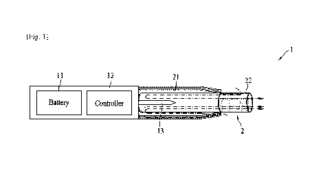
surface.
[12] The heating structure may further include an absorbing layer
positioned on the
CA 03204928 2023- 7- 12
2
second reflective layer.
[13] The emissivity of the absorbing layer may be about 1.
[14] The SPR structure may include a first metal prism to at least
partially form a void
area on the first surface.
[15] The SPR structure may further include a second metal prism to at least
partially form
the void area on the first surface together with the first metal prism,
wherein the first
metal prism and the second metal prism may be apart from each other along a
perimeter of the void area.
[16] The first metal prism may define the entire perimeter of the void
area.
[17] The SPR structure may be configured to resonate with light having a
wavelength
ranging from about 380 nm to about 780 nm.
[18] An aerosol generating device includes a light source, and a heating
structure
configured to receive light from the light source, wherein the heating
structure may
include a substrate including a first surface and a second surface opposite to
the first
surface, a surface plasmon resonance (SPR) structure positioned on the first
surface,
and a first reflective layer positioned above the first surface and the SPR
structure, and
including a pass-through area for passing light to the first surface and/or
the SPR
structure and a reflective area for reflecting light to the SPR structure.
[19] A heating structure includes a substrate including a first surface and
a second surface
opposite to the first surface, a surface plasmon resonance (SPR) structure
positioned on
the first surface, and a reflective layer including a third surface facing the
second
surface and a fourth surface opposite to the third surface, wherein the
reflective layer
may include a diffuse reflection feature formed on the third surface while
facing the
second surface.
[20] The substrate may further include a diffuse reflection feature formed
on the second
surface while facing the third surface.
[21] The diffuse reflection feature of the substrate and the diffuse
reflection feature of the
second reflective layer may have the substantially same shape.
[22] The diffuse reflection feature of the substrate and the diffuse
reflection feature of the
second reflective layer may at least partially contact each other.
[23] The diffuse reflection feature may be formed over the third surface
facing the second
surface.
[24] The reflective layer may be formed of a metal material.
[25] A distance between the third surface and the fourth surface may range
from greater
than 0 nm to less than or equal to about 15 nm.
[26] The heating structure may further include an absorbing layer including
a fifth surface
facing the fourth surface and a sixth surface opposite to the fifth surface.
[27] The emissivity of the absorbing layer may be about 1.
CA 03204928 2023- 7- 12
3
[28] The SPR structure may include a first metal prism to form a void area
on the first
surface.
[29] The SPR structure may further include a second metal prism to form the
void area on
the first surface together with the first metal prism, wherein the first metal
prism and
the second metal prism may be apart from each other along a perimeter of the
void
area.
[30] The first metal prism may define the entire perimeter of the void
area.
[31] The void area may have a diameter ranging from about 300 nm to about
600 nm.
[32] An aerosol generating device includes a light source, and a heating
structure
configured to receive light from the light source, wherein the heating
structure may
include a substrate including a first surface and a second surface opposite to
the first
surface, a surface plasmon resonance (SPR) structure positioned on the first
surface,
and a reflective layer including a third surface facing the second surface and
a fourth
surface opposite to the third surface, wherein the reflective layer may
include a diffuse
reflection feature formed on the third surface while facing the second
surface.
Advantageous Effects of Invention
[33] According to an embodiment, heat may be uniformly generated from a
heating
structure by the substantially same level of excitation of free electrons.
According to an
embodiment, when a heating structure is applied to heat target(s), a target
may be
locally heated, or at least a portion of target(s) among a plurality of
targets may be
heated. According to an embodiment, a heating area of a heating structure may
increase. The effects of the heating structure and the aerosol generating
device
including the same according to an embodiment may not be limited to the above-
mentioned effects, and other unmentioned effects may be clearly understood
from the
following description by one of ordinary skill in the art.
Brief Description of Drawings
[34] The foregoing and other aspects, features, and advantages of
embodiments in the
disclosure will become apparent from the following detailed description with
reference
to the accompanying drawings.
[35] FIGS. 1 to 3 are diagrams illustrating examples of an aerosol
generating article
inserted into an aerosol generating device according to an embodiment.
[36] FIGS. 4 and 5 are diagrams illustrating examples of an aerosol
generating article
according to an embodiment.
[37] FIG. 6 is a block diagram of an aerosol generating device according to
an em-
bodiment.
[38] FIG. 7 is a perspective view of a heating structure according to an
embodiment.
[39] FIG. 8 is an enlarged view of a portion of the heating structure of
FIG. 7.
CA 03204928 2023- 7- 12
4
[40] FIG. 9 is a plan view of a portion of the heating structure of FIG. 8.
[41] FIG. 10 is a cross-sectional view of the heating structure of FIG. 9,
as viewed along
line 10-10.
[42] FIG. 11 is a plan view of a portion of a heating structure according
to an em-
bodiment.
[43] FIG. 12 is a view schematically illustrating a heating structure
according to an em-
bodiment.
[44] FIG. 13 is a view schematically illustrating a heating structure
according to an em-
bodiment.
[45] FIG. 14 is a view schematically illustrating a heating structure
according to an em-
bodiment.
[46] FIG. 15 is a view schematically illustrating a heating structure
according to an em-
bodiment.
[47] FIG. 16 is an enlarged view of an interface between a substrate and a
reflective layer
according to an embodiment.
[48] FIGS. 17 to 19 are views illustrating a method of forming a reflective
layer on a
substrate according to an embodiment.
[49] FIG. 20 is a diagram of an aerosol generating device according to an
embodiment.
Mode for the Invention
[50] The terms used in the embodiments are selected from among common terms
that are
currently widely used, in consideration of their function in the disclosure.
However,
the terms may become different according to an intention of one of ordinary
skill in the
art, a precedent, or the advent of new technology. Also, in particular cases,
the terms
are discretionally selected by the applicant of the disclosure, and the
meaning of those
terms will be described in detail in the corresponding part of the detailed
description.
Therefore, the terms used in the disclosure are not merely designations of the
terms,
but the terms are defined based on the meaning of the terms and content
throughout the
disclosure.
[51] It will be understood that when a certain part "includes" a certain
component, the part
does not exclude another component but may further include another component,
unless the context clearly dictates otherwise. Also, terms such as "unit,"
"module," etc.,
as used in the specification may refer to a part for processing at least one
function or
operation and may be implemented as hardware, software, or a combination of
hardware and software.
[52] Hereinbelow, embodiments of the disclosure will be described in detail
with
reference to the accompanying drawings so that the embodiments may be readily
im-
plemented by one of ordinary skill in the technical field to which the
disclosure
CA 03204928 2023- 7- 12
5
pertains. However, the present invention may be implemented in many different
forms
and is not limited to the embodiments described herein.
[53] Hereinafter, embodiments of the disclosure will be described in detail
with reference
to the drawings.
[54] FIGS. 1 to 3 are diagrams illustrating examples of an aerosol
generating article
inserted into an aerosol generating device.
[55] Referring to FIG. 1, an aerosol generating device 1 may include a
battery 11, a
controller 12, and a heater 13. Referring to FIGS. 2 and 3, the aerosol
generating
device 1 may further include a vaporizer 14. In addition, an aerosol
generating article 2
(e.g., a cigarette) may be inserted into an inner space of the aerosol
generating device
1.
[56] The aerosol generating device 1 shown in FIGS. 1 to 3 may include
components
related to an embodiment described herein. Therefore, it is to be understood
by one of
ordinary skill in the art to which the disclosure pertains that the aerosol
generating
device 1 may further include other general-purpose components in addition to
the ones
shown in FIGS. 1 to 3.
[57] In addition, although it is shown that the heater 13 is included in
the aerosol
generating device 1 in FIGS. 2 and 3, the heater 13 may be omitted as needed.
[58] FIG. 1 illustrates a linear alignment of the battery 11, the
controller 12, and the heater
13. FIG. 2 illustrates a linear alignment of the battery 11, the controller
12, the
vaporizer 14, and the heater 13. FIG. 3 illustrates a parallel alignment of
the vaporizer
14 and the heater 13. However, the internal structure of the aerosol
generating device 1
is not limited to what is shown in FIGS. 1 to 3. That is, the alignments of
the battery
11, the controller 12, the heater 13, and the vaporizer 14 may be changed
depending on
the design of the aerosol generating device 1.
[59] When the aerosol generating article 2 is inserted into the aerosol
generating device 1,
the aerosol generating device 1 may operate the heater 13 and/or the vaporizer
14 to
generate an aerosol. The aerosol generated by the heater 13 and/or the
vaporizer 14
may pass through the aerosol generating article 2 into the user.
[60] Even when the aerosol generating article 2 is not inserted in the
aerosol generating
device 1, the aerosol generating device 1 may heat the heater 13, as needed.
[61] The battery 11 may supply power to be used to operate the aerosol
generating device
1. For example, the battery 11 may supply power to heat the heater 13 or the
vaporizer
14, and may supply power required for the controller 12 to operate. In
addition, the
battery 11 may supply power required to operate a display, a sensor, a motor,
or the
like installed in the aerosol generating device 1.
[62] The controller 12 may control the overall operation of the aerosol
generating device
1. Specifically, the controller 12 may control respective operations of other
CA 03204928 2023- 7- 12
6
components included in the aerosol generating device 1, in addition to the
battery 11,
the heater 13, and the vaporizer 14. In addition, the controller 12 may verify
a state of
each of the components of the aerosol generating device 1 to determine whether
the
aerosol generating device 1 is in an operable state.
[63] The controller 12 may include at least one processor. The at least one
processor may
be implemented as an array of a plurality of logic gates, or may be
implemented as a
combination of a general-purpose microprocessor and a memory in which a
program
executable by the microprocessor is stored. In addition, it is to be
understood by those
having ordinary skill in the art to which the disclosure pertains that the at
least one
processor may be implemented in other types of hardware.
[64] The heater 13 may be heated by the power supplied by the battery 11.
For example,
when an aerosol generating article is inserted in the aerosol generating
device 1, the
heater 13 may be disposed outside the aerosol generating article. The heated
heater 13
may thus raise the temperature of an aerosol generating material in the
aerosol
generating article.
[65] The heater 13 may be an electrically resistive heater. For example,
the heater 13 may
include an electrically conductive track, and the heater 13 may be heated as a
current
flows through the electrically conductive track. However, the heater 13 is not
limited
to the foregoing example, and any example of heating the heater 13 up to a
desired
temperature may be applicable without limitation. Here, the desired
temperature may
be preset in the aerosol generating device 1 or may be set by the user.
[66] For another example, the heater 13 may be an induction heater.
Specifically, the
heater 13 may include an electrically conductive coil for heating the aerosol
generating
article in an induction heating manner, and the aerosol generating article may
include a
susceptor to be heated by the induction heater.
[67] For example, the heater 13 may include a tubular heating element, a
plate-shaped
heating element, a needle-shaped heating element, or a rod-shaped heating
element,
and may heat the inside or outside of the aerosol generating article 2
according to the
shape of a heating element.
[68] In addition, the heater 13 may be provided as a plurality of heaters
in the aerosol
generating device 1. In this case, the plurality of heaters 13 may be disposed
to be
inserted into the aerosol generating article 2 or may be disposed outside the
aerosol
generating article 2. In addition, some of the plurality of heaters 13 may be
disposed to
be inserted into the aerosol generating article 2, and the rest may be
disposed outside
the aerosol generating article 2. However, the shape of the heater 13 is not
limited to
what is shown in FIGS. 1 through 3 but may be provided in various shapes.
[69] The vaporizer 14 may heat a liquid composition to generate an aerosol,
and the
generated aerosol may pass through the aerosol generating article 2 into the
user. That
CA 03204928 2023- 7- 12
7
is, the aerosol generated by the vaporizer 14 may travel along an airflow path
of the
aerosol generating device 1, and the airflow path may be configured such that
the
aerosol generated by the vaporizer 14 may pass through the aerosol generating
article
into the user.
[70] For example, the vaporizer 14 may include a liquid storage (e.g., a
reservoir), a liquid
transfer means, and a heating element. However, embodiments are not limited
thereto.
For example, the liquid storage, the liquid transfer means, and the heating
element may
be included as independent modules in the aerosol generating device 1.
[71] The liquid storage may store the liquid composition. For example, the
liquid com-
position may be a liquid including a tobacco-containing material having a
volatile
tobacco flavor ingredient, or a liquid including a non-tobacco material. The
liquid
storage may be manufactured to be detachable and attachable from and to the
vaporizer
14, or may be manufactured in an integral form with the vaporizer 14.
[72] The liquid composition may include, for example, water, a solvent,
ethanol, a plant
extract, a fragrance, a flavoring agent, or a vitamin mixture. The fragrance
may
include, for example, menthol, peppermint, spearmint oil, various fruit flavor
in-
gredients, and the like. However, embodiments are not limited thereto. The
flavoring
agent may include ingredients that provide the user with a variety of flavors
or scents.
The vitamin mixture may be a mixture of at least one of vitamin A, vitamin B,
vitamin
C, or vitamin E. However, embodiments are not limited thereto. The liquid com-
position may also include an aerosol former such as glycerin and propylene
glycol.
[73] The liquid transfer means may transfer the liquid composition in the
liquid storage to
the heating structure. The liquid transfer means may be, for example, a wick
such as
cotton fiber, ceramic fiber, glass fiber, or porous ceramic. However,
embodiments are
not limited thereto.
[74] The heating element may be an element configured to heat the liquid
composition
transferred by the liquid transfer means. The heating element may be, for
example, a
metal heating wire, a metal heating plate, a ceramic heater, or the like.
However, em-
bodiments are not limited thereto. In addition, the heating element may
include a
conductive filament such as a nichrome wire, and may be arranged in a
structure
wound around the liquid transfer means. The heating element may be heated as a
current is supplied and may transfer heat to the liquid composition in contact
with the
heating element, and may thereby heat the liquid composition. As a result, an
aerosol
may be generated.
[75] For example, the vaporizer 14 may also be referred to as a cartomizer
or an atomizer.
However, embodiments are not limited thereto.
[76] Meanwhile, the aerosol generating device 1 may further include general-
purpose
components in addition to the battery 11, the controller 12, the heater 13,
and the
CA 03204928 2023- 7- 12
8
vaporizer 14. For example, the aerosol generating device 1 may include a
display that
outputs visual information and/or a motor that outputs tactile information. In
addition,
the aerosol generating device 1 may include at least one sensor (e.g., a puff
sensor, a
temperature sensor, an insertion detection sensor for an aerosol generating
article, etc.).
In addition, the aerosol generating device 1 may be manufactured to have a
structure
allowing external air to be introduced or internal gas to flow out even while
the aerosol
generating article 2 is inserted.
[77] Although not shown in FIGS. 1 to 3, the aerosol generating device 1
may constitute a
system along with a separate cradle. For example, the cradle may be used to
charge the
battery 11 of the aerosol generating device 1. Alternatively, the cradle may
be used to
heat the heater 13, with the cradle and the aerosol generating device 1
coupled.
[78] The aerosol generating article 2 may be similar to a conventional
combustible
cigarette. For example, the aerosol generating article 2 may be divided into a
first
portion including an aerosol generating material and a second portion
including a filter
or the like. Alternatively, the second portion of the aerosol generating
article 2 may
also include the aerosol generating material. For example, the aerosol
generating
material provided in the form of granules or capsules may be inserted into the
second
portion.
[79] The first portion may be entirely inserted into the aerosol generating
device 1, and
the second portion may be exposed outside. Alternatively, only the first
portion may be
partially inserted into the aerosol generating device 1, or the first portion
may be
entirely into the aerosol generating device 1 and the second portion may be
partially
inserted into the aerosol generating device 1. The user may inhale the aerosol
with the
second portion in their mouth. In this case, the aerosol may be generated as
external air
passes through the first portion, and the generated aerosol may pass through
the second
portion into the mouth of the user.
[80] For example, the external air may be introduced through at least one
air path formed
in the aerosol generating device 1. In this example, the opening or closing
and/or the
size of the air path formed in the aerosol generating device 1 may be adjusted
by the
user. Accordingly, an amount of atomization, a sense of smoking, or the like
may be
adjusted by the user. As another example, the external air may be introduced
into the
inside of the aerosol generating article 2 through at least one hole formed on
a surface
of the aerosol generating article 2.
[81] Hereinafter, examples of the aerosol generating article 2 will be
described with
reference to FIGS. 4 and 5.
[82] FIGS. 4 and 5 are diagrams illustrating examples of an aerosol
generating article.
[83] Referring to FIG. 4, the aerosol generating article 2 may include a
tobacco rod 21
and a filter rod 22. The first portion and the second portion described above
with
CA 03204928 2023- 7- 12
9
reference to FIGS. 1 to 3 may include the tobacco rod 21 and the filter rod
22, re-
spectively.
[84] Although the filter rod 22 is illustrated as having a single segment
in FIG. 4, em-
bodiments are not limited thereto. That is, alternatively, the filter rod 22
may include a
plurality of segments. For example, the filter rod 22 may include a segment
that cools
an aerosol and a segment that filters a predetermined ingredient contained in
an
aerosol. In addition, the filter rod 22 may further include at least one
segment that
performs another function, as needed.
[85] The diameter of the aerosol generating article 2 may be in a range of
5 mm to 9 mm,
and the length thereof may be about 48 mm. However, embodiments are not
limited
thereto. For example, the length of the tobacco rod 21 may be about 12 mm, the
length
of a first segment of the filter rod 22 may be about 10 mm, the length of a
second
segment of the filter rod 22 may be about 14 mm, and the length of a third
segment of
the filter rod 22 may be about 12 mm. However, embodiments are not limited
thereto.
[86] The aerosol generating article 2 may be wrapped with at least one
wrapper 24. The
wrapper 24 may have at least one hole through which external air is introduced
or
internal gas flows out. As an example, the aerosol generating article 2 may be
wrapped
with one wrapper 24. As another example, the aerosol generating article 2 may
be
wrapped with two or more of wrappers 24 in an overlapping manner. For example,
the
tobacco rod 21 may be wrapped with a first wrapper 241, and the filter rod 22
may be
wrapped with wrappers 242, 243, and 244. In addition, the aerosol generating
article 2
may be entirely wrapped again with a single wrapper 245. For example, when the
filter
rod 22 includes a plurality of segments, the plurality of segments may be
wrapped with
the wrappers 242, 243, and 244, respectively.
[87] The first wrapper 241 and the second wrapper 242 may be formed of
general filter
wrapping paper. For example, the first wrapper 241 and the second wrapper 242
may
be porous wrapping paper or non-porous wrapping paper. In addition, the first
wrapper
241 and the second wrapper 242 may be formed of oilproof paper and/or an
aluminum
laminated wrapping material.
[88] The third wrapper 243 may be formed of hard wrapping paper. For
example, the
basis weight of the third wrapper 243 may be in a range of 88 g/m2 to 96 g/m2,
and
may be desirably in a range of 90 g/m2 to 94 g/m2. In addition, the thickness
of the
third wrapper 243 may be in a range of 120 [cm to 130 [cm, and may be
desirably about
125 [cm.
[89] The fourth wrapper 244 may be formed of oilproof hard wrapping paper.
For
example, the basis weight of the fourth wrapper 244 may be in a range of 88
g/m2 to 96
g/m2, and may be desirably in a range of 90 g/m2 to 94 g/m2. In addition, the
thickness
of the fourth wrapper 244 may be in a range of 120 [cm to 130 [cm, and may be
CA 03204928 2023- 7- 12
10
desirably about 125 [cm.
[90] The fifth wrapper 245 may be formed of sterile paper (e.g., MFW).
Here, the sterile
paper (MFW) may refer to paper specially prepared such that it has enhanced
tensile
strength, water resistance, smoothness, or the like, compared to general
paper. For
example, the basis weight of the fifth wrapper 245 may be in a range of 57
g/m2 to 63
g/m2, and may be desirably 60 g/m2. In addition, the thickness of the fifth
wrapper 245
may be in a range of 64 [cm to 70 [cm, and may be desirably about 67 [cm.
[91] The fifth wrapper 245 may have a predetermined material internally
added thereto.
The material may be, for example, silicon. However, embodiments are not
limited
thereto. Silicon may have properties, such as, for example, heat resistance
which is
characterized by less change by temperature, oxidation resistance which refers
to re-
sistance to oxidation, resistance to various chemicals, water repellency
against water,
or electrical insulation. However, silicon may not be necessarily used, but
any material
having such properties described above may be applied to (or used to coat) the
fifth
wrapper 245 without limitation.
[92] The fifth wrapper 245 may prevent the aerosol generating article 2
from burning. For
example, there may be a probability that the aerosol generating article 2
burns when
the tobacco rod 21 is heated by the heater 13. Specifically, when the
temperature rises
above the ignition point of any one of the materials included in the tobacco
rod 21, the
aerosol generating article 2 may burn. Even in this case, it may still be
possible to
prevent the aerosol generating article 2 from burning because the fifth
wrapper 245
includes a non-combustible material.
[93] In addition, the fifth wrapper 245 may prevent an aerosol generating
device (e.g.,
holder) from being contaminated by substances produced in the aerosol
generating
article 2. Liquid substances may be produced in the aerosol generating article
2 when a
user puffs. For example, as an aerosol generated in the aerosol generating
article 2 is
cooled by external air, such liquid substances (e.g., moisture, etc.) may be
produced.
As the aerosol generating article 2 is wrapped with the fifth wrapper 245, the
liquid
substances generated within the aerosol generating article 2 may be prevented
from
leaking out of the aerosol generating article 2.
[94] The tobacco rod 21 may include an aerosol generating material. The
aerosol
generating material may include, for example, at least one of glycerin,
propylene
glycol, ethylene glycol, dipropylene glycol, diethylene glycol, triethylene
glycol,
tetraethylene glycol, or ()ley' alcohol. However, embodiments are not limited
thereto.
The tobacco rod 21 may also include other additives such as, for example, a
flavoring
agent, a wetting agent, and/or an organic acid. In addition, the tobacco rod
21 may
include a flavoring liquid such as menthol or a moisturizing agent that is
added as
being sprayed onto the tobacco rod 21.
CA 03204928 2023- 7- 12
11
[95] The tobacco rod 21 may be manufactured in various forms. For example,
the tobacco
rod 21 may be formed as a sheet or a strand. Alternatively, the tobacco rod 21
may be
formed of tobacco leaves finely cut from a tobacco sheet. In addition, the
tobacco rod
21 may be enveloped by a thermally conductive material. The thermally
conductive
material may be, for example, a metal foil such as aluminum foil. However, em-
bodiments are not limited thereto. For example, the thermally conductive
material en-
veloping the tobacco rod 21 may evenly distribute the heat transferred to the
tobacco
rod 21 to improve the conductivity of the heat to be applied to the tobacco
rod 21,
thereby improving the taste of tobacco. In addition, the thermally conductive
material
enveloping the tobacco rod 21 may function as a susceptor heated by an
induction
heater. In this case, although not shown, the tobacco rod 21 may further
include an ad-
ditional susceptor in addition to the thermally conductive material enveloping
the
outside thereof.
[96] The filter rod 22 may be a cellulose acetate filter. However, there is
no limit to the
shape of the filter rod 22. For example, the filter rod 22 may be a
cylindrical rod, or a
tubular rod including a hollow therein. The filter rod 22 may also be a recess-
type rod.
For example, when the filter rod 22 includes a plurality of segments, at least
one of the
segments may be manufactured in a different shape.
[97] A first segment of the filter rod 22 may be a cellulose acetate
filter. For example, the
first segment may be a tubular structure including a hollow therein. The first
segment
may prevent internal materials of the tobacco rod 21 from being pushed back
when the
heater 13 is inserted into the tobacco rod 21 and may cool the aerosol. A
desirable
diameter of the hollow included in the first segment may be adopted from a
range of 2
mm to 4.5 mm. However, embodiments are not limited thereto.
[98] A desirable length of the first segment may be adopted from a range of
4 mm to 30
mm. However, embodiments are not limited thereto. Desirably, the length of the
second segment may be 10 mm. However, embodiments are not limited thereto.
[99] The first segment may have a hardness that is adjustable through an
adjustment of the
content of a plasticizer in the process of manufacturing the first segment. In
addition,
the first segment may be manufactured by inserting a structure such as a film
or a tube
of the same or different materials therein (e.g., in the hollow).
[100] A second segment of the filter rod 22 may cool an aerosol generated
as the heater 13
heats the tobacco rod 21. The user may thus inhale the aerosol cooled down to
a
suitable temperature.
[101] The length or diameter of the second segment may differ according to
the shape of
the aerosol generating article 2. For example, a desirable length of the
second segment
may be adopted from a range of 7 mm to 20 mm. Desirably, the length of the
second
segment may be about 14 mm. However, embodiments are not limited thereto.
CA 03204928 2023- 7- 12
12
[102] The second segment may be manufactured by weaving a polymer fiber. In
this case,
a flavoring liquid may be applied to a fiber formed of a polymer. As another
example,
the second segment may be manufactured by weaving a separate fiber to which a
flavoring liquid is applied and the fiber formed of the polymer together. As
still
another example, the second segment may be formed with a crimped polymer
sheet.
[103] For example, the polymer may be prepared with a material selected
from the group
consisting of polyethylene (PE), polypropylene (PP), polyvinyl chloride (PVC),
polyethylene terephthalate (PET), polylactic acid (PLA), cellulose acetate
(CA,) and
aluminum foil.
[104] As the second segment is formed with the woven polymer fiber or the
crimped
polymer sheet, the second segment may include a single channel or a plurality
of
channels extending in a longitudinal direction. A channel used herein may
refer to a
path through which a gas (e.g., air or aerosol) passes.
[105] For example, the second segment formed with the crimped polymer sheet
may be
formed of a material having a thickness between about 5 [cm and about 300 [cm,
for
example, between about 10 [cm and about 250 [cm. In addition, the total
surface area of
the second segment may be between about 300 mm2/mm and about 1000 mm2/mm.
Further, an aerosol cooling element may be formed from a material having a
specific
surface area between about 10 mm2/mg and about 100 mm2/mg.
[106] Meanwhile, the second segment may include a thread containing a
volatile flavor in-
gredient. The volatile flavor ingredient may be menthol. However, embodiments
are
not limited thereto. For example, the thread may be filled with a sufficient
amount of
menthol to provide at least 1.5 mg of menthol to the second segment.
[107] A third segment of the filter rod 22 may be a cellulose acetate
filter. A desirable
length of the third segment may be adopted from a range of 4 mm to 20 mm. For
example, the length of the third segment may be about 12 mm. However,
embodiments
are not limited thereto.
[108] The third segment may be manufactured such that a flavor is generated
by spraying a
flavoring liquid onto the third segment in the process of manufacturing the
third
segment. Alternatively, a separate fiber to which the flavoring liquid is
applied may be
inserted into the third segment. An aerosol generated in the tobacco rod 21
may be
cooled as it passes through the second segment of the filter rod 22, and the
cooled
aerosol may pass through the third segment into the user. Accordingly, when a
flavoring element is added to the third segment, the flavor carried to the
user may last
much longer.
[109] In addition, the filter rod 22 may include at least one capsule 23.
Here, the capsule 23
may perform a function of generating a flavor or a function of generating an
aerosol.
For example, the capsule 23 may have a structure in which a liquid containing
a
CA 03204928 2023- 7- 12
13
fragrance is wrapped with a film. The capsule 23 may have a spherical or
cylindrical
shape. However, embodiments are not limited thereto.
[110] Referring to FIG. 5, an aerosol generating article 3 may further
include a front end
plug 33. The front end plug 33 may be disposed on one side of a tobacco rod 31
opposite to a filter rod 32. The front end plug 33 may prevent the tobacco rod
31 from
escaping to the outside, and may also prevent an aerosol liquefied in the
tobacco rod 31
during smoking from flowing into an aerosol generating device (e.g., the
aerosol
generating device 1 of FIGS. 1 to 3).
[111] The filter rod 32 may include a first segment 321 and a second
segment 322. Here,
the first segment 321 may correspond to the first segment of the filter rod 22
of FIG. 4,
and the second segment 322 may correspond to the third segment of the filter
rod 22 of
FIG. 4.
[112] The diameter and the total length of the aerosol generating article 3
may correspond
to the diameter and the total length of the aerosol generating article 2 of
FIG. 4. For
example, the length of the front end plug 33 may be about 7 mm, the length of
the
tobacco rod 31 may be about 15 mm, the length of the first segment 321 may be
about
12 mm, and the length of the second segment 322 may be about 14 mm. However,
em-
bodiments are not limited thereto.
[113] The aerosol generating article 3 may be wrapped by at least one
wrapper 35. The
wrapper 35 may have at least one hole through which external air flows inside
or
internal gas flows outside. For example, the front end plug 33 may be wrapped
with a
first wrapper 351, the tobacco rod 31 may be wrapped with a second wrapper
352, the
first segment 321 may be wrapped with a third wrapper 353, and the second
segment
322 may be wrapped with a fourth wrapper 354. In addition, the aerosol
generating
article 3 may be entirely wrapped again with a fifth wrapper 355.
[114] In addition, at least one perforation 36 may be formed in the fifth
wrapper 355. For
example, the perforation 36 may be formed in an area surrounding the tobacco
rod 31.
However, embodiments are not limited thereto. The perforation 36 may perform a
function of transferring heat generated by the heater 13 shown in FIGS. 2 and
3 to the
inside of the tobacco rod 31.
[115] In addition, the second segment 322 may include at least one capsule
34. Here, the
capsule 34 may perform a function of generating a flavor or a function of
generating an
aerosol. For example, the capsule 34 may have a structure in which a liquid
containing
a fragrance is wrapped with a film. The capsule 34 may have a spherical or
cylindrical
shape. However, embodiments are not limited thereto.
[116] The first wrapper 351 may be a combination of general filter wrapping
paper and a
metal foil such as aluminum foil. For example, the total thickness of the
first wrapper
351 may be in a range of 45 [cm to 55 [cm, and may be desirably about 50.3
[cm.
CA 03204928 2023- 7- 12
14
Further, the thickness of the metal foil of the first wrapper 351 may be in a
range of 6
[cm to 7 [cm, and may be desirably 6.3 [cm. In addition, the basis weight of
the first
wrapper 351 may be in a range of 50 g/m2 to 55 g/m2, and may be desirably 53
g/m2.
[117] The second wrapper 352 and the third wrapper 353 may be formed with
general filter
wrapping paper. For example, the second wrapper 352 and the third wrapper 353
may
be porous wrapping paper or non-porous wrapping paper.
[118] For example, the porosity of the second wrapper 352 may be 35000 CU.
However,
embodiments are not limited thereto. Further, the thickness of the second
wrapper 352
may be in a range of 70 [cm to 80 [cm, and may be desirably about 78 [cm. In
addition,
the basis weight of the second wrapper 352 may be in a range of 20 g/m2 to 25
g/m2,
and may be desirably 23.5 g/m2.
[119] For example, the porosity of the third wrapper 353 may be 24000 CU.
However, em-
bodiments are not limited thereto. Further, the thickness of the third wrapper
353 may
be in a range of 60 [cm to 70 [cm, and may be desirably about 68 [cm. In
addition, the
basis weight of the third wrapper 353 may be in a range of 20 g/m2 to 25 g/m2,
and
may be desirably 21 g/m2.
[120] The fourth wrapper 354 may be formed with polylactic acid (PLA)
laminated paper.
Here, the PLA laminated paper may refer to three-ply paper including a paper
layer, a
PLA layer, and a paper layer. For example, the thickness of the fourth wrapper
354
may be in a range of 100 [cm to 120 [cm, and may be desirably about 110 [cm.
In
addition, the basis weight of the fourth wrapper 354 may be in a range of 80
g/m2 to
100 g/m2, and may be desirably 88 g/m2.
[121] The fifth wrapper 355 may be formed of sterile paper (e.g., MFW).
Here, the sterile
paper (MFW) may refer to paper specially prepared such that it has enhanced
tensile
strength, water resistance, smoothness, or the like, compared to general
paper. For
example, the basis weight of the fifth wrapper 355 may be in a range of 57
g/m2 to 63
g/m2, and may be desirably about 60 g/m2. Further, the thickness of the fifth
wrapper
355 may be in a range of 64 [cm to 70 [cm, and may be desirably about 67 [cm.
[122] The fifth wrapper 355 may have a predetermined material internally
added thereto.
The material may be, for example, silicon. However, embodiments are not
limited
thereto. Silicon may have properties, such as, for example, heat resistance
which is
characterized by less change by temperature, oxidation resistance which refers
to re-
sistance to oxidation, resistance to various chemicals, water repellency
against water,
or electrical insulation. However, silicon may not be necessarily used, but
any material
having such properties described above may be applied to (or used to coat) the
fifth
wrapper 355 without limitation.
[123] The front end plug 33 may be formed of cellulose acetate. For
example, the front end
plug 33 may be manufactured by adding a plasticizer (e.g., triacetin) to
cellulose
CA 03204928 2023- 7- 12
15
acetate tow. The mono denier of a filament of the cellulose acetate tow may be
in a
range of 1.0 to 10.0, and may be desirably in a range of 4.0 to 6Ø The mono
denier of
the filament of the front end plug 33 may be more desirably about 5Ø In
addition, a
cross section of the filament of the front end plug 33 may be Y-shaped. The
total
denier of the front end plug 33 may be in a range of 20000 to 30000, and may
be
desirably in a range of 25000 to 30000. The total denier of the front end plug
33 may
be more desirably 28000.
[124] In addition, as needed, the front end plug 33 may include at least
one channel, and a
cross-sectional shape of the channel may be provided in various ways.
[125] The tobacco rod 31 may correspond to the tobacco rod 21 described
above with
reference to FIG. 4. Thus, a detailed description of the tobacco rod 31 will
be omitted
here.
[126] The first segment 321 may be formed of cellulose acetate. For
example, the first
segment may be a tubular structure including a hollow therein. The first
segment 321
may be manufactured by adding a plasticizer (e.g., triacetin) to cellulose
acetate tow.
For example, the mono denier and the total denier of the first segment 321 may
be the
same as the mono denier and the total denier of the front end plug 33.
[127] The second segment 322 may be formed of cellulose acetate. The mono
denier of a
filament of the second segment 322 may be in a range of 1.0 to 10.0, and may
be
desirably in a range of 8.0 to 10Ø The mono denier of the filament of the
second
segment 322 may be more desirably 9Ø In addition, a cross section of the
filament of
the second segment 322 may be Y-shaped. The total denier of the second segment
322
may be in a range of 20000 to 30000, and may be desirably 25000.
[128] FIG. 6 is a block diagram of an aerosol generating device 400
according to an em-
bodiment.
[129] The aerosol generating device 400 may include a controller 410, a
sensing unit 420,
an output unit 430, a battery 440, a heater 450, a user input unit 460, a
memory 470,
and a communication unit 480. However, the internal structure of the aerosol
generating device 400 is not limited to what is shown in FIG. 6. It is to be
understood
by one of ordinary skill in the art to which the disclosure pertains that some
of the
components shown in FIG. 6 may be omitted or new components may be added
according to the design of the aerosol generating device 400.
[130] The sensing unit 420 may sense a state of the aerosol generating
device 400 or a state
of an environment around the aerosol generating device 400, and transmit
sensing in-
formation obtained through the sensing to the controller 410. Based on the
sensing in-
formation, the controller 410 may control the aerosol generating device 400 to
control
operations of the heater 450, restrict smoking, determine whether an aerosol
generating
article (e.g., a cigarette, a cartridge, etc.) is inserted, display a
notification, and perform
CA 03204928 2023- 7- 12
16
other functions.
[131] The sensing unit 420 may include at least one of a temperature sensor
422, an
insertion detection sensor 424, or a puff sensor 426. However, embodiments are
not
limited thereto.
[132] The temperature sensor 422 may sense a temperature at which the
heater 450 (or an
aerosol generating material) is heated. The aerosol generating device 400 may
include
a separate temperature sensor for sensing the temperature of the heater 450,
or the
heater 450 itself may perform a function as a temperature sensor.
Alternatively, the
temperature sensor 422 may be arranged around the battery 440 to monitor the
tem-
perature of the battery 440.
[133] The insertion detection sensor 424 may sense whether the aerosol
generating article
is inserted or removed. The insertion detection sensor 424 may include, for
example, at
least one of a film sensor, a pressure sensor, a light sensor, a resistive
sensor, a ca-
pacitive sensor, an inductive sensor, or an infrared sensor, which may sense a
signal
change by the insertion or removal of the aerosol generating article.
[134] The puff sensor 426 may sense a puff from a user based on various
physical changes
in an airflow path or airflow channel. For example, the puff sensor 426 may
sense the
puff of the user based on any one of a temperature change, a flow change, a
voltage
change, and a pressure change.
[135] The sensing unit 420 may further include at least one of a
temperature/humidity
sensor, an atmospheric pressure sensor, a magnetic sensor, an acceleration
sensor, a
gyroscope sensor, a position sensor (e.g., a global positioning system (GPS)),
a
proximity sensor, or a red, green, blue (RGB) sensor (e.g., an illuminance
sensor), in
addition to the sensors 422 through 426 described above. A function of each
sensor
may be intuitively inferable from its name by one of ordinary skill in the
art, and thus,
a more detailed description thereof will be omitted here.
[136] The output unit 430 may output information about the state of the
aerosol generating
device 400 and provide the information to the user. The output unit 430 may
include at
least one of a display 432, a haptic portion 434, or a sound outputter 436.
However,
embodiments are not limited thereto. When the display 432 and a touchpad are
provided in a layered structure to form a touchscreen, the display 432 may be
used as
an input device in addition to an output device.
[137] The display 432 may visually provide information about the aerosol
generating
device 400 to the user. The information about the aerosol generating device
400 may
include, for example, a charging/discharging state of the battery 440 of the
aerosol
generating device 400, a preheating state of the heater 450, an
insertion/removal state
of the aerosol generating article, a limited usage state (e.g., an abnormal
article
detected) of the aerosol generating device 400, or the like, and the display
432 may ex-
CA 03204928 2023- 7- 12
17
ternally output the information. The display 432 may be, for example, a liquid-
crystal
display panel (LCD), an organic light-emitting display panel (OLED), or the
like. The
display 432 may also be in the form of a light-emitting diode (LED) device.
[138] The haptic portion 434 may provide information about the aerosol
generating device
400 to the user in a haptic way by converting an electrical signal into a
mechanical
stimulus or an electrical stimulus. The haptic portion 434 may include, for
example, a
motor, a piezoelectric element, or an electrical stimulation device.
[139] The sound outputter 436 may provide information about the aerosol
generating
device 400 to the user in an auditory way. For example, the sound outputter
436 may
convert an electrical signal into a sound signal and externally output the
sound signal.
[140] The battery 440 may supply power to be used to operate the aerosol
generating
device 400. The battery 440 may supply power to heat the heater 450. In
addition, the
battery 440 may supply power required for operations of the other components
(e.g.,
the sensing unit 420, the output unit 430, the user input unit 460, the memory
470, and
the communication unit 480) included in the aerosol generating device 400. The
battery 440 may be a rechargeable battery or a disposable battery. The battery
440 may
be, for example, a lithium polymer (LiPoly) battery. However, embodiments are
not
limited thereto.
[141] The heater 450 may receive power from the battery 440 to heat the
aerosol
generating material. Although not shown in FIG. 6, the aerosol generating
device 400
may further include a power conversion circuit (e.g., a direct current (DC)-to-
DC
(DC/DC) converter) that converts power of the battery 440 and supplies the
power to
the heater 450. In addition, when the aerosol generating device 400 generates
an
aerosol in an induction heating manner, the aerosol generating device 400 may
further
include a DC-to-alternating current (AC) (DC/AC) converter that converts DC
power
of the battery 440 into AC power.
[142] The controller 410, the sensing unit 420, the output unit 430, the
user input unit 460,
the memory 470, and the communication unit 480 may receive power from the
battery
440 to perform functions. Although not shown in FIG. 6, the aerosol generating
device
400 may further include a power conversion circuit, for example, a low dropout
(LDO)
circuit or a voltage regulator circuit, that converts power of the battery 440
and
supplies the power to respective components.
[143] In an embodiment, the heater 450 may be formed of any suitable
electrically resistive
material. The electrically resistive material may be a metal or a metal alloy
including,
for example, titanium, zirconium, tantalum, platinum, nickel, cobalt,
chromium,
hafnium, niobium, molybdenum, tungsten, tin, gallium, manganese, iron, copper,
stainless steel, nichrome, or the like. However, embodiments are not limited
thereto. In
addition, the heater 450 may be implemented as a metal heating wire, a metal
heating
CA 03204928 2023- 7- 12
18
plate on which an electrically conductive track is arranged, a ceramic heating
element,
or the like, but is not limited thereto.
[144] In an embodiment, the heater 450 may be an induction heater. For
example, the
heater 450 may include a susceptor that heats the aerosol generating material
by
generating heat through a magnetic field applied by a coil.
[145] In an embodiment, the heater 450 may include a plurality of heaters.
For example,
the heater 450 may include a first heater for heating an aerosol generating
article and a
second heater for heating a liquid.
[146] The user input unit 460 may receive information input from the user
or may output
information to the user. For example, the user input unit 460 may include a
keypad, a
dome switch, a touchpad (e.g., a contact capacitive type, a pressure resistive
film type,
an infrared sensing type, a surface ultrasonic conduction type, an integral
tension mea-
surement type, a piezo effect method, etc.), a jog wheel, a jog switch, or the
like.
However, embodiments are not limited thereto. In addition, although not shown
in
FIG. 6, the aerosol generating device 400 may further include a connection
interface
such as a universal serial bus (USB) interface, and may be connected to
another
external device through the connection interface such as a USB interface to
transmit
and receive information or to charge the battery 440.
[147] The memory 470, which is hardware for storing various pieces of data
processed in
the aerosol generating device 400, may store data processed by the controller
410 and
data to be processed thereby. The memory 470 may include at least one type of
storage
medium of a flash memory type memory, a hard disk type memory, a multimedia
card
micro type memory, a card type memory (e.g., an SD or XE memory), a random
access
memory (RAM), a static random access memory (SRAM), a read-only memory
(ROM), an electrically erasable programmable read-only memory (EEPROM), a pro-
grammable read-only memory (PROM), a magnetic memory, a magnetic disk, or an
optical disk. The memory 470 may store an operating time of the aerosol
generating
device 400, a maximum number of puffs, a current number of puffs, at least one
tem-
perature profile, data associated with a smoking pattern of the user, or the
like.
[148] The communication unit 480 may include at least one component for
communicating
with another electronic device. For example, the communication unit 480 may
include
a short-range wireless communication unit 482 and a wireless communication
unit 484.
[149] The short-range wireless communication unit 482 may include a
Bluetooth commu-
nication unit, a BLE communication unit, a near field communication unit, a
WLAN
(Wi-Fi) communication unit, a ZigBee communication unit, an infrared data as-
sociation (IrDA) communication unit, a Wi-Fi direct (WFD) communication unit,
an
ultra-wideband (UWB) communication unit, and an Ant+ communication unit.
However, embodiments are not limited thereto.
CA 03204928 2023- 7- 12
19
[150] The wireless communication unit 484 may include, for example, a
cellular network
communicator, an Internet communicator, a computer network (e.g., a local area
network (LAN) or a wide-area network (WAN)) communicator, or the like.
However,
embodiments are not limited thereto. The wireless communication unit 484 may
use
subscriber information (e.g., international mobile subscriber identity (IMSI))
to
identify and authenticate the aerosol generating device 400 in a communication
network.
[151] The controller 410 may control the overall operation of the aerosol
generating device
400. In an embodiment, the controller 410 may include at least one processor.
The at
least one processor may be implemented as an array of a plurality of logic
gates, or
may be implemented as a combination of a general-purpose microprocessor and a
memory in which a program executable by the microprocessor is stored. In
addition, it
is to be understood by one of ordinary skill in the art to which the
disclosure pertains
that it may be implemented in other types of hardware.
[152] The controller 410 may control the temperature of the heater 450 by
controlling the
supply of power from the battery 440 to the heater 450. For example, the
controller
410 may control the supply of power by controlling the switching of a
switching
element between the battery 440 and the heater 450. In another example, a
direct
heating circuit may control the supply of power to the heater 450 according to
a control
command from the controller 410.
[153] The controller 410 may analyze a sensing result obtained by the
sensing of the
sensing unit 420 and control processes to be performed thereafter. For
example, the
controller 410 may control power to be supplied to the heater 450 to start or
end an
operation of the heater 450 based on the sensing result obtained by the
sensing unit
420. As another example, the controller 410 may control an amount of power to
be
supplied to the heater 450 and a time for which the power is to be supplied,
such that
the heater 450 may be heated up to a predetermined temperature or maintained
at a
desired temperature, based on the sensing result obtained by the sensing unit
420.
[154] The controller 410 may control the output unit 430 based on the
sensing result
obtained by the sensing unit 420. For example, when the number of puffs
counted
through the puff sensor 426 reaches a preset number, the controller 410 may
inform the
user that the aerosol generating device 400 is to be ended soon, through at
least one of
the display 432, the haptic portion 434, or the sound outputter 436.
[155] In an embodiment, the controller 410 may control a power supply time
and/or a
power supply amount for the heater 450 according to a state of the aerosol
generating
article sensed by the sensing unit 420. For example, when the aerosol
generating article
is in an over-humidified state, the controller 410 may control the power
supply time for
an inductive coil to increase a preheating time, compared to a case where the
aerosol
CA 03204928 2023- 7- 12
20
generating article is in a general state.
[156] One embodiment may also be implemented in the form of a recording
medium
including instructions executable by a computer, such as a program module
executable
by the computer. A computer-readable medium may be any available medium that
can
be accessed by a computer and includes a volatile medium, a non-volatile
medium, a
removable medium, and a non-removable medium. In addition, the computer-
readable
medium may include both a computer storage medium and a communication medium.
The computer storage medium includes all of a volatile medium, a non-volatile
medium, a removable medium, and a non-removable medium implemented by any
method or technology for storage of information such as computer-readable in-
structions, data structures, program modules or other data. The communication
medium typically includes computer-readable instructions, data structures,
other data
in modulated data signals such as program modules, or other transmission
mechanisms, and includes any information transfer medium.
[157] FIG. 7 is a perspective view of a heating structure according to an
embodiment, and
FIG. 8 is an enlarged view of a portion of the heating structure of FIG. 7.
FIG. 9 is a
plan view of a portion of the heating structure of FIG. 8, and FIG. 10 is a
cross-
sectional view of the heating structure of FIG. 9, as viewed along line 10-10.
[158] Referring to FIGS. 7 to 10, a heating structure 550 according to an
embodiment may
be configured to generate heat by surface plasmon resonance. "Surface plasmon
resonance" refers to the collective oscillation of electrons propagating along
an
interface of metal particles with a medium. For example, the collective
oscillation of
electrons of metal particles may be caused by light propagating from the
outside of the
heating structure 550. The excitation of electrons of metal particles may
generate
thermal energy, and the generated thermal energy may be transferred within an
en-
vironment to which the heating structure 550 is applied. In an embodiment, the
heating
structure 550 may be configured to heat another target (e.g., an aerosol
generating
article) by transferring the generated heat to the target.
[159] The heating structure 550 may include a substrate 551 having a first
surface 551A
(e.g., a surface oriented in a +Z direction) and a second surface 551B (e.g.,
a surface
oriented in a -Z direction) opposite to the first surface 551A.
[160] In an embodiment, the substrate 551 may have a plate shape. The first
surface 551A
and/or the second surface 551B may be substantially flat. According to
embodiments,
the substrate 551 may have any shape suitable for generating heat. For
example, the
substrate 551 may be implemented in a substantially cylindrical shape with the
first
surface 551A as an outer surface and the second surface 551B as an inner
surface.
[161] In an embodiment, the substrate 551 may be formed of various
materials. For
example, the substrate 551 may be formed of glass, silicon (Si), silicon oxide
(Sift),
CA 03204928 2023- 7- 12
21
sapphire, polystyrene, polymethyl methacrylate, and/or any other suitable
material. In
some embodiments, the substrate 551 may be formed of any one or combination of
glass, silicon (Si), silicon oxide (5i02), and sapphire. In some embodiments,
the
substrate 551 may include a material having a relatively low heat transfer
coefficient.
This may allow heat to be only transferred to a partial area on the substrate
551.
[162] In an embodiment, the substrate 551 may exhibit electrical
conductivity. In an em-
bodiment, the substrate 551 may exhibit electrical insulating properties.
[163] In an embodiment, the substrate 551 may be formed of a material
having any thermal
conductivity suitable for use in an environment in which the heating structure
550 is
disposed. For example, the substrate 551 may have a thermal conductivity of
about 0.6
Watts per meter-Kelvin (W/mK) or less, about 1 W/mK to about 2 W/mK, about 2
W/
mK to about 5 W/mK, about 5 W/mK to about 10 W/mK, about 10 W/mK to about
100 W/mK, or about 100 W/mK to about 200 W/mK, at 1 bar pressure and 25 C tem-
perature. In some embodiments, the substrate 551 may have a thermal
conductivity of
about 0.6 W/mK or less, about 1.3 W/mK, about 148 W/mK, or about 46.06 W/mK,
at
1 bar pressure and 25 C temperature.
[164] The heating structure 550 may include a plurality of metal prisms 554
positioned on
the first surface 551A of the substrate 551. The plurality of metal prisms 554
may
include a plurality of metal particles deposited on the substrate 551 through
any
suitable deposition process (e.g., physical vapor deposition).
[165] In an embodiment, the plurality of metal particles forming the
plurality of metal
prisms 554 may be nanoscale. For example, the plurality of metal particles may
have
an average maximum diameter of about 1 [cm or less. In some embodiments, the
plurality of metal particles may have an average maximum diameter of about 700
nm
or less, about 600 nm or less, about 500 nm or less, about 400 nm or less,
about 300
nm or less, about 200 nm or less, about 150 nm or less, or about 100 nm or
less.
[166] In an embodiment, the plurality of metal particles may be formed of
any material
suitable for generating heat. For example, the plurality of metal particles
may include
at least one of gold, silver, copper, palladium, platinum, aluminum, titanium,
nickel,
chromium, iron, cobalt, manganese, rhodium, and ruthenium, or a combination
thereof.
[167] In an embodiment, the plurality of metal particles may be formed of
any material
suitable for generating heat by interacting with light of a certain wavelength
band (e.g.,
a visible light wavelength band, that is, about 380 nm to about 780 nm). For
example,
the plurality of metal particles may include at least one of gold, silver,
copper,
palladium, and platinum, or a combination thereof.
[168] In some embodiments, the plurality of metal particles may be formed
of a metal
material having an average maximum absorbance. Here, the average maximum ab-
sorbance may be defined as an absorbance substantially having a peak in a
specific
CA 03204928 2023- 7- 12
22
wavelength band. The specific wavelength band corresponding to the absorbance
may
be understood as a wavelength band in which the plurality of metal particles
resonate.
For example, the plurality of metal particles may be formed of a metal
material having
an average maximum absorbance in a wavelength band between about 430 nm and
about 450 nm, between about 480 nm and about 500 nm, between about 490 nm and
about 510 nm, between about 500 nm and about 520 nm, between about 550 nm and
about 570 nm, between about 600 nm and about 620 nm, between about 620 nm and
about 640 nm, between about 630 nm and about 650 nm, between about 640 nm and
about 660 nm, between about 680 nm and about 700 nm, or between about 700 nm
and
about 750 nm. The average maximum absorbance of the plurality of metal
particles
may vary depending on the type of the substrate 551 in addition to the metal
material,
the size of the metal prism 554 formed by the plurality of metal particles,
and/or the
shape of the metal prisms 554.
[169] In an embodiment, the plurality of metal prisms 554 may define a void
area VA
surrounded by the plurality of metal prisms 554 on the first surface 551A of
the
substrate 551. For example, the void area VA may have a substantially circular
or el-
liptical shape, and the plurality of metal prisms 554 may be arranged in a
circum-
ferential direction of the void area VA.
[170] In an embodiment, the void area VA may have an average maximum
diameter of
about 10 nm or greater, about 50 nm or greater, about 90 nm or greater, about
100 nm
or greater, about 150 nm or greater, about 200 nm or greater, about 300 nm or
greater,
about 350 nm or greater, about 450 nm or greater, or about 500 nm or greater.
In some
embodiments, the void area VA may have an average maximum diameter of about
450
nm or greater. In some embodiments, the void area VA may have an average
maximum diameter of about 350 nm or greater. In some embodiments, the void
area
VA may have an average maximum diameter of about 300 nm or greater.
[171] In an embodiment, the void area VA may have an average maximum
diameter of
about 1,000 nm or less, about 900 nm or less, about 800 nm or less, about 700
nm or
less, about 600 nm or less, or about 550 nm or less. In some embodiments, the
void
area VA may have an average maximum diameter of about 600 nm or less.
[172] In an embodiment, the plurality of metal prisms 554 may each include
a first base
surface 554A (e.g., a lower base surface) facing the first surface 551A of the
substrate
551, a second base surface 554B (e.g., an upper base surface) opposite to the
first base
surface 554A, and a plurality of side surfaces 554C1, 554C2, and 554C3 between
the
first base surface 554A and the second base surface 554B.
[173] In an embodiment, the first base surface 554A and the second base
surface 554B may
be substantially parallel to each other.
[174] In an embodiment, the first base surface 554A and/or the second base
surface 554B
CA 03204928 2023- 7- 12
23
may be substantially flat.
[175] In an embodiment, the distance between the first base surface 554A
and the second
base surface 554B (e.g., the thickness of the metal prism 554) may be about 10
nm or
less. When the metal prism 554 has a thickness exceeding 10 nm, the exothermic
reaction of a plurality of metal particles forming the metal prism 554 may
decrease,
and consequently, the thermal efficiency of the heating structure 550 may
decrease.
[176] In an embodiment, the plurality of side surfaces 554C1, 554C2, and
554C3 may be
oriented in different directions. For example, the first side surface 554C1
may be
oriented in a first direction (e.g., a first radial direction), the second
side surface 554C2
may be connected to the first side surface 554C1 and oriented in a second
direction
(e.g., a second radial direction), and the third side surface 554C3 may be
connected to
each of the first side surface 554C1 and the second side surface 554C3 and
oriented in
a third direction (e.g., a third radial direction).
[177] In an embodiment, at least one side surface of the plurality of side
surfaces 554C1,
554C2, and 554C3 may be formed as a substantially curved surface. In some em-
bodiments, the plurality of side surfaces 554C1, 554C2, and 554C3 may be
formed as
curved surfaces having substantially the same curvature. In an embodiment, the
curvature of any one of the plurality of side surfaces 554C1, 554C2, and 554C3
may
be different from the curvature of another side surface.
[178] In an embodiment, the plurality of side surfaces 554C1, 554C2, and
554C3 may be
formed as curved surfaces that are concave toward the center of the metal
prism 554.
In an embodiment, at least one side surface of the plurality of side surfaces
554C1,
554C2, and 554C3 may be formed as a curved surface that is convex from the
center of
the metal prism 554.
[179] In an embodiment, the plurality of metal prisms 554 may include two
side surfaces.
For example, the metal prism 554 may have a substantially semicircular shape
or a
shape close to a semicircle.
[180] In an embodiment, the plurality of metal prisms 554 may be positioned
to be
physically separated from each other on the first surface 551A of the
substrate 551. For
example, the plurality of metal prisms 554 may be apart from each other along
the
perimeter (e.g., the circumference) of the void area VA.
[181] In an embodiment, the plurality of metal prisms 554 may be apart from
each other at
substantially equal intervals. In an embodiment, the interval between any one
pair of
adjacent metal prisms 554 among the plurality of metal prisms 554 may be
different
from the interval between another pair of adjacent metal prisms 554.
[182] FIG. 11 is a plan view of a portion of a heating structure according
to an em-
bodiment.
[183] Referring to FIG. 11, a heating structure 650 according to an
embodiment may
CA 03204928 2023- 7- 12
24
include a substrate 651 and a metal prism 654 positioned on the substrate 651.
The
metal prism 654 may be substantially a single structure and define a plurality
of void
areas VA. For example, the metal prism 654 may substantially define all the
perimeters
of the plurality of void areas VA. The metal prism 654 may include a first
prism area
6541 at one position on the perimeter (e.g., the circumference) of a void area
VA, a
second prism area 6542 at another position on the perimeter (e.g., the
circumference)
of the void area VA, and a third prism area 6543 between the first prism area
6541 and
the second prism area 6542. The first prism area 6541, the second prism area
6542, and
the third prism area 6543 may be integrally and seamlessly connected.
[184] FIG. 12 is a view schematically illustrating a heating
structure according to an em-
bodiment.
[185] Referring to FIG. 12, a heating structure 750 according to
an embodiment may
include a substrate 751 (e.g., the substrate 551 or 651) including a first
surface 751A
and a second surface 751B, a surface plasmon resonance (SPR) structure 754
(e.g., the
metal prism 554 or 654) positioned on the first surface 751A, and a reflective
layer 755
positioned on the second surface 751B. The heating structure 750 may be
configured to
receive light L on the substrate 751 and/or the SPR structure 754.
[186] In an embodiment, the SPR structure 754 may be implemented
as at least one metal
prism (e.g., the metal prism 554 or 654) including a plurality of metal
particles. In an
embodiment, the SPR structure 754 may include a plurality of metal particles
applied
on the first surface 751A of the substrate 751. In an embodiment, the SPR
structure
754 may include at least one metal film formed of a metal material.
[187] A light source emitting the light L may be separated from
the heating structure 750
by a predetermined distance. For example, the distance between the light
source and
the heating structure 750 may be about 40 cm or less, about 35 cm or less,
about 30 cm
or less, about 25 cm or less, about 20 cm or less, about 15 cm or less, about
10 cm or
less, or about 5 cm or less. The distance between the light source and the
heating
structure 750 may be about 5 cm or greater, about 10 cm or greater, about 15
cm or
greater, about 20 cm or greater, or about 25 cm or greater.
[188] The light L may be incident on a spot LS of the substrate
751 and/or the SPR
structure 754. For example, the spot LS may have a size of about 2 mm or less,
about
1.5 mm or less, about 1 mm or less, or about 0.5 mm or less. The spot LS may
have a
size of about 0.2 mm or greater, about 0.4 mm or greater, about 0.6 mm or
greater, or
about 0.8 mm or greater.
[189] The reflective layer 755 may be configured to reflect the
light L passing through the
substrate 751 to the substrate 751 and/or the SPR structures 754. The
reflective layer
755 reflecting the light L passing through the substrate 751 may allow the
substrate
751 and the SPR structures 754 to use the reflected light. As a result, the
light use ef-
CA 03204928 2023- 7- 12
25
ficiency of the heating structure 750 may increase and the heating efficiency
may
increase accordingly.
[190] In an embodiment, the reflective layer 755 may be formed on the
entire second
surface 751B of the substrate 751. In an embodiment, the reflective layer 755
may be
formed locally on the second surface 751B of the substrate 751. For example,
the re-
flective layer 755 may be implemented as a single reflective zone in a partial
area of
the second surface 751B of the substrate 751, or as a plurality of reflective
zones.
[191] The reflective layer 755 may be formed of any material suitable for
reflecting the
light L. In an embodiment, the reflective layer 755 may be formed of a metal
material.
For example, the reflective layer 755 may be formed of at least one of gold,
silver,
copper, and any other metal material suitable for reflection, or a combination
thereof.
[192] The reflective layer 755 may have any thickness suitable for
reflecting the light L.
The thickness of the reflective layer 755 may be predetermined to be a value
suitable
for substantially total reflection of the light L. For example, the reflective
layer 755
may have a thickness of about 15 nm or less, about 12 nm or less, about 10 nm
or less,
about 8 nm or less, or about 5 nm or less. In a preferred example, the
reflective layer
755 may have a thickness of about 10 nm. The thickness of the reflective layer
755
may be determined based on the refractive index of the substrate 751, the
thickness of
the substrate 751, the refractive index of the reflective layer 755, and/or
any other
parameter.
[193] In an embodiment, the reflective layer 755 may directly contact the
second surface
751B of the substrate 751. Alternatively, the reflective layer 755 may be
spaced apart
from the second surface 751B of the substrate 751, and a medium (e.g., air)
may be po-
sitioned between the second surface 751B and the reflective layer 755.
[194] In an embodiment, the heating structure 750 may include an absorbing
layer 756 po-
sitioned on the reflective layer 755. The absorbing layer 756 may be
configured to
absorb a portion of transmitted light that is transmitted through the
reflective layer 755
without being reflected by the reflective layer 755. The absorbing layer 756
may
increase the light use efficiency of the heating structure 750.
[195] In an embodiment, the absorbing layer 756 may be at least partially
applied to the re-
flective layer 755 by coating.
[196] In an embodiment, the absorbing layer 756 may have a substantially
high emissivity.
In some embodiments, the absorbing layer 756 may have an emissivity
substantially
close to 1. The absorbing layer 756 may be implemented as a structure and/or
material
close to a substantially black body. For example, the absorbing layer 756 may
be im-
plemented as a structure having at least one hole through which light may
enter and be
substantially permanently reflected therein. In an embodiment, the absorbing
layer 756
may be implemented as a gray body or a white body.
CA 03204928 2023- 7- 12
26
[197] In an embodiment, the heating structure 750 may include a thermal
imager 760
configured to generate a thermal image. For example, the thermal imager 760
may
generate an image including the thermal distribution of the heating structure
750. In an
embodiment, the thermal imager 760 may be included in an external component of
the
heating structure 750 (e.g., an aerosol generating device 1200 of FIG. 20).
[198] FIG. 13 is a view schematically illustrating a heating structure
according to an em-
bodiment.
[199] Referring to FIG. 13, a heating structure 850 according to an
embodiment may
include a substrate 851 including a first surface 851A and a second surface
851B, a
surface plasmon resonance (SPR) structure 854 positioned on the first surface
851A, a
first reflective layer 855A positioned above the first surface 851A and the
SPR
structure 854, a second reflective layer 855B (e.g., the reflective layer 755
of FIG. 12)
positioned on the second surface 851B, and an absorbing layer 856 (e.g., the
absorbing
layer 756) positioned on the second reflective layer 855B.
[200] In an embodiment, the SPR structure 854 may be implemented as at
least one metal
prism (e.g., the metal prism 554 or 654) including a plurality of metal
particles. In an
embodiment, the SPR structure 854 may include a plurality of metal particles
applied
on the first surface 851A. In an embodiment, the SPR structure 854 may include
at
least one metal film formed of a metal material.
[201] The first reflective layer 855A may diffuse light L that is locally
concentrated toward
the substrate 851 and/or the SPR structure 854 throughout the substrate 851
and/or the
SPR structure 854. When the light L is diffused throughout the substrate 851
and/or the
SPR structure 854, the heating area by surface plasmon resonance may increase.
[202] The first reflective layer 855A may include a reflective area Al
configured to reflect
light L coming from the substrate 851 and/or the SPR structure 854. Incident
light L
received on the reflective area Al may include light L reflecting from the
substrate
851, light L reflecting from the SPR structure 854, or light L penetrating
through the
substrate 851 after reflecting from the second reflective layer 855B.
[203] In an embodiment, the reflective area Al may extend or expand along
the first
surface 851A of the substrate 851. In some embodiments, the reflective area Al
may
have a substantially continuous surface. Alternatively, the reflective area Al
may
include a plurality of discrete surfaces.
[204] In an embodiment, the reflective area Al may be apart from the first
surface 851A of
the substrate 851 and/or the SPR structure 854 by a determined distance.
Alternatively,
the reflective area Al may at least partially contact the first surface 851A
and/or the
SPR structure 854.
[205] In an embodiment, the reflective area Al may be formed of any
material suitable for
reflecting the light L. For example, the reflective area Al may be formed of
gold,
CA 03204928 2023- 7- 12
27
silver, copper, aluminum, or other metal materials suitable for reflection. In
some em-
bodiments, the reflective area Al may be formed of a material suitable for
total re-
flection of the light L.
[206] In an embodiment, the first reflective layer 855A may include at
least one pass-
through area A2 configured to allow the light L to pass through the first
reflective layer
855A and reach the first surface 851A of the substrate 851 and/or the SPR
structure
854. The pass-through area A2 may be formed at any suitable position within
the re-
flective area Al.
[207] In an embodiment, the pass-through area A2 may include an opening.
The opening
may have a size suitable for reducing the amount of light that fails to pass
through the
opening. The opening may have a substantially curved shape, for example, a
circle or
ellipse, or may have a polygonal shape such as a rectangle. In an embodiment,
the
pass-through area A2 may be formed of a material suitable for passing the
light L. For
example, the reflective area Al may be formed of a substantially opaque
material,
while the pass-through area A2 may be formed of a substantially transparent or
translucent material.
[208] FIG. 14 is a view schematically illustrating a heating structure
according to an em-
bodiment.
[209] Referring to FIG. 14, a heating structure 950 according to an
embodiment may
include a substrate 951 including a first surface 951A and a second surface
951B, a
surface plasmon resonance (SPR) structure 954 positioned on the first surface
951A, a
first reflective layer 955A positioned above the first surface 951A and the
SPR
structure 954 and including a reflective area Al configured to reflect light L
and a
pass-through area A2 configured to pass the light L, a second reflective layer
955B po-
sitioned on the second surface 951B, and an absorbing layer 956 positioned on
the
second reflective layer 955B.
[210] The heating structure 950 may have a substantially cylindrical
structure. For
example, the first surface 951A may be oriented toward the outside of the
heating
structure 950 and the second surface 951B may be oriented toward the inside of
the
heating structure 950, whereby the substrate 951 may be arranged to define a
hollow
area S.
[211] The SPR structure 954 and/or the reflective area Al of the first
reflective layer 955A
may at least partially surround the first surface 951A of the substrate 951
and extend or
expand in a circumferential direction of the substrate 951.
[212] The second reflective layer 955B and/or the absorbing layer 956 may
be at least
partially surrounded by the second surface 951B of the substrate 951. The
second re-
flective layer 955B and/or the absorbing layer 956 may define the hollow area
S.
[213] FIG. 15 is a view schematically illustrating a heating structure
according to an em-
CA 03204928 2023- 7- 12
28
bodiment, and FIG. 16 is an enlarged view of an interface between a substrate
and a re-
flective layer according to an embodiment.
[214] Referring to FIGS. 15 and 16, a heating structure 1050 may include a
substrate 1051
including a first surface 1051A and a second surface 1051B, a surface plasmon
resonance (SPR) structure 1054 positioned on the first surface 1051A, a
reflective
layer 1055 including a third surface 1055A facing the second surface 1051B and
a
fourth surface 1055B opposite to the third surface 1055A, and an absorbing
layer 1056
including a fifth surface 1056A facing the fourth surface 1055B and a sixth
surface
1056B opposite to the fifth surface 1056A.
[215] In an embodiment, the SPR structure 1054 may be implemented as at
least one metal
prism (e.g., the metal prism 554 or 654) including a plurality of metal
particles. In an
embodiment, the SPR structure 1054 may include a plurality of metal particles
applied
on the first surface 1051A. In an embodiment, the SPR structure 1054 may
include at
least one metal film formed of a metal material.
[216] In an embodiment, the substrate 1051 may include a first diffuse
reflection feature
1051C formed on the second surface 1051B while facing the third surface 1055A,
and
the reflective layer 1055 may include a second diffuse reflection feature
1055C formed
on the third surface 1055A while facing the second surface 1051B. The second
diffuse
reflection feature 1055C may be configured to reflect light passing through
the
substrate 1051 and proceeding toward the reflective layer 1055, such that the
light may
be reflected in various directions to the inside of the substrate 1051 and
toward the first
surface 1051A of the substrate 1051.
[217] As diffuse reflection occurs (i.e., the light is reflected in various
directions) by the
second diffuse reflection feature 1055C, the area of light transmitted onto
the first
surface 1051A of the substrate 1051 may increase. As the area of the light
transmitted
onto the first surface 1051A of the substrate 1051 increases, the amount of
light
available to the SPR structure 1054 may increase. As a result, the heating
area of the
heating structure 1050 may increase.
[218] In an embodiment, the first diffuse reflection feature 1051C and the
second diffuse
reflection feature 1055C may substantially match each other. To "substantially
match"
may be understood as that both features 1051C and 1055C may have the
substantially
same shape. In some embodiments, the first diffuse reflection feature 1051C
and the
second diffuse reflection feature 1055C may partially contact each other.
[219] In an embodiment, the first diffuse reflection feature 1051C may be
implemented as
a rough structure formed by roughening the second surface 1051B of the
substrate
1051. The first diffuse reflection feature 1051C may have a predetermined
roughness
by, for example, etching (e.g., laser etching) the second surface 1051B. For
example,
the surface roughness Ra of the second surface 1051B on which the first
diffuse re-
CA 03204928 2023- 7- 12
29
flection feature 1051C is formed may be about 0.1 [cm or greater.
[220] In an embodiment, the first diffuse reflection feature 1051C may be
formed over sub-
stantially the entire area of the second surface 1051B, and the second diffuse
reflection
feature 1055C may be formed over substantially the entire area of the third
surface
1055A. In an embodiment, the first diffuse reflection feature 1051C may be
formed in
a part of the second surface 1051B, and the second diffuse reflection feature
1055C
may be formed in a part of the third surface 1055A corresponding to the part
of the
second surface 1051B.
[221] In an embodiment, the substrate 1051 may not include the first
diffuse reflection
feature 1051C. The second surface 1051B of the substrate 1051 and the third
surface
1055A of the reflective layer 1055 may be apart from each other by a
predetermined
distance. The second diffuse reflection feature 1055C formed on the third
surface
1055A of the reflective layer 1055 may reflect light in various directions to
the inside
of the substrate 1051 and toward the first surface 1051A of the substrate
1051, through
a medium between the second surface 1051B and the third surface 1055A. In this
em-
bodiment, the second diffuse reflection feature 1055C may be implemented as a
rough
structure formed by roughening (e.g., laser etching) the third surface 1055A
of the re-
flective layer 1055. For example, the surface roughness Ra of the second
diffuse re-
flection feature 1055C may be about 0.1 [cm or greater.
[222] FIGS. 17 to 19 are views illustrating a method of forming a
reflective layer on a
substrate according to an embodiment.
[223] Referring to FIG. 17, a method may include an operation of preparing
a substrate
1151 including a first surface 1151A and a second surface 1151B opposite to
the first
surface 1151A. For example, the substrate 1151 may be formed of glass, silica,
and/or
any suitable material.
[224] Referring to FIG. 18, the method may include an operation of
roughening the second
surface 1151B of the substrate 1151. The second surface 1151B may be
implemented
to be substantially uneven. For example, the second surface 1151B may be im-
plemented as a rough surface by etching (e.g., laser etching). The substrate
1151 may
include a diffuse reflection feature 1151C formed on the second surface 1151B.
The
second surface 1151B including the diffuse reflection feature 1151C may have a
surface roughness Ra suitable for reducing the regular reflection of light and
reducing
interference. For example, the surface roughness Ra may be about 0.1 [cm or
greater.
[225] Referring to FIG. 19, the method may include an operation of
depositing a plurality
of metal particles on the second surface 1151B of the substrate 1151. After
the
plurality of metal particles are deposited on the second surface 1151B, a
reflective
layer 1155 including a third surface 1155A facing the second surface 1151B and
a
fourth surface 1155B opposite to the third surface 1155A may be formed. Since
the
CA 03204928 2023- 7- 12
30
plurality of metal particles are deposited on the second surface 1151B, the
third surface
1155A facing the second surface 1151B may also include a diffuse reflection
feature
implemented as a substantially rough surface.
[226] FIG. 20 is a diagram of an aerosol generating device according to an
embodiment.
[227] Referring to FIG. 20, an aerosol generating device 1200 (e.g., the
aerosol generating
device 1 or 400) may include at least one heating structure 1250 (e.g., the
heater 13 or
450 and/or the heating structure 550, 650, 750, 850, or 950) configured to
heat an
aerosol generating article (e.g., the aerosol generating article 2 or 3), and
at least one
light source 1255 configured to emit light toward the at least one heating
structure
1250. Meanwhile, although FIG. 20 illustrates the aerosol generating device
1200
including a controller 1210 (e.g., the controller 12 or 410) configured to
control the
heating structure 1250 and/or the light source 1255, and a battery 1240 (e.g.,
the
battery 11 or 440) configured to supply electrical energy to the controller
1210, other
components may be included or omitted.
[228] In an embodiment, the aerosol generating device 1200 may include a
single heating
structure 1250. The heating structure 1250 may at least partially surround a
cavity in
which an aerosol generating article is to be placed. The heating structure
1250 may
have a structure in which, for example, the substrate 551, 651, 751, 951,
1051, or 1151
at least partially has a curved surface.
[229] In an embodiment, the aerosol generating device 1200 may include a
plurality of
heating structures 1250. The plurality of heating structures 1250 may be
positioned in
different portions based on the cavity in which an aerosol generating article
is to be
placed. Metal materials of metal prisms included in the plurality of heating
structures
1250 may be the same or different.
[230] In an embodiment, the light source 1255 may be configured to transmit
an optical
signal toward the heating structure 1250 at a predetermined angle. For
example, the
light source 1255 may transmit an optical signal at an angle that may cause
total re-
flection on a surface of the heating structure 1250 (e.g., a surface of the
substrate 551,
651, 751, 851, 951, 1051, or 1151 and/or the surfaces 654B, 654C1, 654C2, and
654C3 of the metal prism 554, 654, 754, 854, or 954). In an embodiment, the
light
source 1255 may transmit an optical signal toward the heating structure 1250
at any
angle.
[231] In an embodiment, the light source 1255 may be configured to transmit
light in an ul-
traviolet band, a visible band, and/or an infrared band. In some embodiments,
the light
source 1255 may be configured to transmit light in the visible band (e.g.,
about 380 nm
to about 780 nm).
[232] In some embodiments, the light source 1255 may be configured to
transmit light in a
band corresponding to a material of metal particles of a metal prism (e.g.,
the metal
CA 03204928 2023- 7- 12
31
prism 554, 654, 754, 854, or 954) included in the heating structure 1250. For
example,
the light source 1255 may transmit light in a wavelength band corresponding to
an
average maximum absorbance according to the material of the metal particles.
In an
embodiment in which a metal prism is formed of gold, the light source 1255 may
transmit light having a wavelength of about 638 nm.
[233] In an embodiment, the light source 1255 may transmit light at any
suitable output.
For example, the light source 1255 may transmit light at an output of about
1,000 mW.
[234] In an embodiment, the light source 1255 may include a light-emitting
diode and/or a
laser. The light-emitting diode and/or the laser may be of a type and/or size
suitable for
being included in the aerosol generating device 1200. For example, the laser
may
include a solid-state laser and/or a semiconductor laser.
[235] In an embodiment, the aerosol generating device 1200 may include a
plurality of
light sources 1255. The plurality of light sources 1255 may be implemented as
light
sources of the same type. In an embodiment, at least a portion of the
plurality of light
sources 1255 may be implemented as different types of light sources.
[236] In an embodiment, at least one light source 1255 among the plurality
of light sources
1255 may be configured to irradiate a portion of the heating structure 1250.
[237] In an embodiment, a portion of the heating structure 1250 irradiated
by any one light
source 1255 of the plurality of light sources 1255 may be different from a
portion of
the heating structure 1250 irradiated by another light source 1255. For
example, the
plurality of light sources 1255 may irradiate different portions of a single
heating
structure 1250 or irradiate a plurality of heating structures 1250.
[238] In an embodiment, the plurality of light sources 1255 may be
configured to irradiate
substantially at the same time. In an embodiment, an irradiation point in time
of any
one light source 1255 of the plurality of light sources 1255 may be different
from an ir-
radiation point in time of another light source 1255.
[239] In an embodiment, the plurality of light sources 1255 may irradiate
the heating
structure 1250 for substantially the same time. In an embodiment, an
irradiation time
of any one light source 1255 of the plurality of light sources 1255 may be
different
from an irradiation time of another light source 1255.
[240] In an embodiment, the plurality of light sources 1255 may transmit
light of sub-
stantially the same wavelength band. In an embodiment, a band of light
radiated by any
one light source 1255 of the plurality of light sources 1255 may be different
from a
band of light radiated by another light source 1255.
[241] In an embodiment, the plurality of light sources 1255 may irradiate
the heating
structure 1250 with substantially the same illuminance. In an embodiment, an
il-
luminance of any one light source 1255 of the plurality of light sources 1255
may be
different from an illuminance of another light source 1255.
CA 03204928 2023- 7- 12
32
[242]
The embodiments of the disclosure are intended to be illustrative and
not restrictive.
Various modifications may be made to the detailed description of the
disclosure
including the accompanying scope of claims and equivalents. Any of the em-
bodiment(s) described herein may be used in combination with any other em-
bodiment(s) described herein.
CA 03204928 2023- 7- 12