Note: Descriptions are shown in the official language in which they were submitted.
1
Hopper comprising cooling elements
Description
Field of the invention
The present disclosure is related to the field of chemical manufacturing, in
particular the
present disclosure provides a novel hopper comprising cooling elements.
Background of the invention
A hopper, also named a collection container for particles, is a device that
can collect a
material, in particular a granular or particulate material, hold it and
dispense it on demand. A hopper
is a container with a large opening on its top to easily receive the material
to hold and a narrow
bottom end to dispense the material in a controlled manner. Hoppers may
alternatively be described
as containers with converging sides, i.e. having sort of a funnel shape.
Hoppers are widely used in the
manufacturing of chemicals, such as fertilizer particles.
EP0444338A1 (Cominco Ltd, 1991) discloses a device for cooling solid
particles. The device
comprises a plurality of parallel, spaced, vertical heat exchanger plates, a
feed hopper, and a
discharge hopper. The heat exchanger plates are connected to a fluid inlet and
outlet located on a
side of the hopper. The device reduces the attrition and abrasion of the
particles it cools.
U520200017416A1 (thyssenkrupp AG, 2020) discloses a system comprising a
fluidized bed
granulator, a cooler and a product screen. The product screen comprises an
exit for oversized
particles which is connected to the fluidized bed granulator via one or more
crushers.
The functions of hoppers available today are limited to its primary functions,
i.e. collecting,
storing and dispensing a material. There is a need to develop novel hoppers
that may cool down the
material that hoppers hold.
Summary of the invention
It was found that it was possible to develop a novel type of hoppers that
comprise cooling
elements in its buffer compartment, so that the temperature of the particles
collected, and
dispensed by the hopper would decrease during their stay in the hopper. The
buffer compartment is
the section of a hopper where materials, such as particles, are provided or
held before use or
distribution.
CA 03205096 2023-7- 13
2
The present inventors also found a method to revamp a conventional hopper,
i.e. a hopper
not comprising any cooling function. It is particularly interesting to revamp
an existing device, since
this allows to solve a problem by modifying only one device, the hopper, and
does not require
changes on other devices, such as the devices connected to the hopper. Also a
revamped hopper
does not use more space in the plant than the original hopper.
Revamping a device allows the plant to improve its capacity or capabilities
with minimal cost
and minimal interruption to the plant.
The present invention is defined by the appended set of claims.
In a first aspect, the present disclosure is related to a hopper comprising a
buffer
compartment defined by side walls, a top end comprising an opening adapted for
receiving solid
particles, and a bottom end comprising an opening adapted for dispensing the
solid particles from
the buffer compartment. The buffer compartment comprises a plurality of
essentially vertically
positioned cooling plate-like elements for cooling the solid particles in the
buffer compartment.
In another aspect, the present disclosure is related to a method for operating
the hopper
according to the present disclosure comprising the steps of: a) activating the
cooling effect of the
plurality of the cooling plate-like elements; b) providing solid particles,
e.g. as a feed or a stream, to
the top end of the hopper e.g. in a continuous or intermittent manner; and c)
dispensing cooled solid
particles via the opening of the bottom end of the hopper e.g. in a continuous
or intermittent
manner.
In another aspect, the present disclosure is related to a method for operating
a system
according to the present disclosure, comprising the steps of:
I) activating the cooling effect of the plurality of the cooling plate-like
elements of said
hopper;
II) directing a melt to a granulator, in particular a melt comprising one or
more selected from
the group of urea, ammonium salt, nitrate salt, and/or mixtures thereof;
III) granulating the melt in the granulator thereby obtaining particles, in
particular in a
fluidized bed granulator;
IV) separating the obtained particles based on predetermined size ranges into
fractions of
on-specs solid particles, undersized solid particles and oversized solid
particles; and
V) directing any oversized solid particles obtained to said hopper;
VI) providing said any oversized solid particles to the top end of said
hopper, e.g. in a
continuous or intermittent manner; and
VII) dispensing cooled solid particles via the opening of the bottom end of
said hopper, e.g. in
a continuous or intermittent manner,
CA 03205096 2023-7- 13
3
VIII) dispensing the cooled solid particles from the hopper to a crusher to
reduce the particle
size of the solid particles, and
IX) separating and directing any undersized solid particles obtained from the
crusher to the
granulator.
In another aspect, the present disclosure is related to a method for
production of solid
particles, using the present hopper, comprising the steps of:
a) activating the cooling effect of the plurality of the cooling plate-like
elements of said
hopper;
b) providing solid particles to the top end of said hopper e.g. in a
continuous or intermittent
manner; and
c) dispensing cooled solid particles via the opening of the bottom end of said
hopper e.g. in a
continuous or intermittent manner,
d) dispensing the cooled solid particles from the hopper to a crusher to
reduce the particle
size of the solid particles, and
e) separating and directing any undersized solid particles obtained from the
crusher to the
granulator,
wherein said solid particles provided in b) are obtained by the steps of:
i) directing a melt to a granulator, in particular a melt comprising one or
more
selected from the group of urea, ammonium salt, nitrate salt, and/or mixtures
thereof;
ii) granulating the melt in the granulator thereby obtaining particles, in
particular in a
fluidized bed granulator,
iii) separating the obtained particles based on predetermined size ranges into
fractions of on-specs solid particles, undersized solid particles and
oversized solid
particles; and
iv) directing any oversized solid particles obtained to said hopper as said
solid particles of
step b.
In another aspect, the present disclosure is related to a method for producing
solid particles
in a granulator, in particular a fluidized bed granulator, using the hopper
according to the present
disclosure, comprising the steps of: a) directing a melt to a granulator, in
particular a melt comprising
one or more selected from the group of urea, ammonium salt, nitrate salt,
and/or mixtures thereof;
b) granulating the melt in the granulator thereby obtaining on-specs solid
particles, undersized solid
particles and oversized solid particles; c) activating the cooling effect of
the plurality of the cooling-
plate-like elements of the hopper according to the present disclosure; d)
directing the oversized solid
particles to the hopper according to the present disclosure; e) dispensing the
cooled oversized solid
CA 03205096 2023-7- 13
4
particles from the hopper according to the present disclosure to a crusher,
thereby obtaining
undersized solid particles, and optionally also on-size solid particles; and
f) directing the undersized
solid particles obtained from the crusher in step e) to the granulator.
In another aspect, the present disclosure is related to the use of the hopper
according to the
present disclosure for dispensing solid particles to a crusher.
In another aspect, the present disclosure is related to the use of the hopper
according to the
present disclosure in the manufacturing of solid fertilizer particles, such as
sized solid fertilizer
particles.
Brief description of the figures
The following description of the figure 1 of a specific embodiment of a hopper
according to the present
disclosure is only given by way of example and is not intended to limit the
present explanation, its
application or use.
Figure 2 is showing another view of the same embodiment as Figure 1, after a
rotation of 90
around a vertical axis. In the figures, identical reference numerals refer to
the same or similar parts
and features.
Detailed description of the invention
Unless otherwise defined, all terms used in disclosing the invention,
including technical and scientific
terms, have the meaning as commonly understood by one of ordinary skill in the
art to which this
invention belongs. By means of further guidance, term definitions are included
to better appreciate
the teaching of the present invention.
All references cited in this description are hereby deemed to be incorporated
in their entirety by way
of reference.
As used herein, the following terms have the following meanings:
"A", "an", and "the" as used herein refers to both singular and plural
referents unless the
context clearly dictates otherwise. By way of example, "a device" refers to
one or more than one
compartment.
"About" as used herein referring to a measurable value such as a parameter, an
amount, a
temporal duration, and the like, is meant to encompass variations of +/-20 %
or less, in particular +/-
10 % or less, more in particular +/-5 % or less, even more in particular +/-1
% or less, and still more in
particular +/-0.1 % or less of and from the specified value, in so far such
variations are appropriate to
perform in the disclosed invention. However, it is to be understood that the
value to which the
CA 03205096 2023-7- 13
5
modifier "about" refers is itself also specifically disclosed.
"Comprise", "comprising", and "comprises" and "comprised of" as used herein
are
synonymous with "include", "including", "includes" or "contain", "containing",
"contains" and are
inclusive or open-ended terms that specifies the presence of what follows e.g.
component and do
not exclude or preclude the presence of additional, non-recited components,
features, element,
members, steps, known in the art or disclosed therein.
The recitation of numerical ranges by endpoints includes all numbers and
fractions subsumed
within that range, as well as the recited endpoints.
The expression "weight percent", "%wt" or "weight%", here and throughout the
description
unless otherwise defined, refers to the relative weight of the respective
component based on the
overall weight of the formulation.
In a first aspect, the present disclosure is related to a hopper comprising a
buffer
compartment defined by side walls, a top end comprising an opening for
receiving solid particles, and
a bottom end comprising an opening for dispensing the solid particles from the
buffer compartment.
The buffer compartment comprises a plurality of essentially vertically
positioned cooling plate-like
elements for cooling the solid particles in the buffer compartment.
A hopper is a very convenient apparatus to regulate the flow of solid
particles between two
other apparatus in a production process. For example, it can be used to
transfer solid particles or
granules from a conveyor belt to a crusher. It may dispense solid particles at
a constant rate in a
precise area. A hopper comprises a buffer compartment. The buffer compartment
may be defined by
the interior of the hopper. The buffer compartment may be provided by the
interior volume of the
hopper. The buffer compartment may be defined by side walls, top end, and
bottom end of the
hopper, in which solid particles can be held, e.g. before being distributed.
The height of the hopper
and the buffer compartment may be the same. The top end of the hopper is at
least partially open to
allow receive the solid particles. Alternatively, the top end of the hopper
may comprise a lid that may
be opened during operations, to allow provision of the solid particles to the
hopper and its buffer
compartment. Solid particles may be provided to the hopper or its buffer
compartment in a
continuous or intermittent manner. Thus, the top end is adapted to receive
solid particles in a
continuous or intermittent manner. The solid particles may be provided to the
hopper via a conveyor
belt, a heat exchanger, a pipe or any other suitable apparatus. A product
chute or funnel may be
installed above the opening of the top end of the hopper to guide the solid
particles into the hopper.
The bottom end, or bottom section, of the hopper is where the particles are
dispensed, e.g. to
another apparatus of the production process. The solid particles may be
allowed to exit the hopper
or its buffer compartment in a continuous or intermittent manner. Thus, the
bottom end or section is
adapted to allow exit of solid particles in a continuous or intermittent
manner. The bottom end may
CA 03205096 2023-7- 13
6
be partly or completely opened when dispensing the solid particles, such as
granules. The bottom
end may comprise a movable device such as a lid that may be closed to prevent
any particles from
leaving the hopper, or to be partly opened, or to be completely opened.
The feed of solid particles into the hopper or its buffer compartment, and the
exit of said solid
particles from the hopper or its buffer compartment which may be adapted to be
performed in
continuous or intermittent manners, are e.g. performed in the same manner,
i.e. if feeding is
performed continuously so is also the exit, likewise if feeding is performed
intermittently so is also
the exit. The hopper or its buffer compartment may always contain solid
particles during operation
thereof.
The opening of the bottom end of the hopper or buffer compartment is often
smaller, i.e. has
a smaller area, than the opening of the top end of the hopper or buffer
compartment to dispense the
particles in a more precise manner. The opening of the top end should be large
enough to receive all
the solid particles that the hopper or buffer compartment is adapted for to
receive. The size and
shape of the opening may be adapted to any process or any equipment that
provides the solid
particles to the hopper. The geometry and size of the bottom end may be
adapted, depending on the
purpose of the hopper or any apparatus that it dispenses the solid particles
to.
During operations, the hopper and its buffer compartment is receiving and/or
containing
solid particles, and may be kept at least partially full, meaning that there
are always solid particles in
the buffer compartment of the hopper. This ensures that the dispensing flow of
the hopper is always
constant. While the solid particles are in the hopper, they may exchange heat
with the ambient
atmosphere. However, the solid particles may be tightly packed, and the heat
exchange with the
ambient atmosphere is therefore limited.
The present inventors were faced with the problem that the temperature of the
particles as
received by a hopper was too high to dispense them to a subsequent apparatus.
This was especially
observed in view of the heat provided during production of solid particles via
granulation processes,
which were subsequently forwarded to a hopper. For example, if the particles
are to be dispensed
from a hopper to a crusher, it is important that the solid particles do not
exceed a temperature
above which the solid particles do not crush well. Indeed, if solid particles
are above a certain
temperature in a crusher, they will tend to cake upon crushing and form a kind
of paste instead of
crushing into smaller free-flowing solid particles. Furthermore, it was
observed that some particles
provided to the hopper still contained a liquid phase inside. This is possible
since particles may be
produced from a hot melt, in particular in granulators, such as fluidized bed
granulator, drum
granulator or pan granulator. Such liquid would then spill into the crusher
when the particles are
crushed, and solidify inside the crusher, eventually blocking the crusher
after accumulation.
CA 03205096 2023-7- 13
7
In order to solve this problem, it was envisioned and then determined to add
cooling plate-
like elements, which may be essentially vertically positioned, into and
therefore contained in the
buffer compartment of the hopper. Once the particles are provided into the
hopper, some of them
come into contact with the cooling plate-like elements and their temperature
is reduced. Due to
particles movement within the buffer compartment, the cooled particles may
come into contact with
other warmer particles and reduce their temperature as well. It may not be
necessary that all the
solid particles present in the hopper come into contact with the cooling
elements to achieve a
reduction in the overall temperature of the stream of solid particles being
dispensed.
It could be envisioned to cool the walls of the hopper to cool the particles
inside it, but placing the
cooling elements in the buffer compartment allows a faster cooling since the
surface of contact of
the solid particles with the cooled parts is much greater with the present
solution.
Adding the cooling elements in the hopper allows the cooling of solid
particles without any
change or major impact to the devices connected to the hopper, e.g. allowing
for minimized
interference and change to common or original equipment setups.
The cooling plate-like elements may have any kind of geometry. Commercial
products often
have a square or rectangle geometry. The geometry of the elements may be
adapted to the
geometry of the buffer compartment of the hopper. The cooling plate-like
elements must fit into the
buffer compartment of the hopper. The elements may have a geometry similar to
the geometry of
the buffer compartment, i.e. if the buffer compartment has a trapezoidal cross-
section, such as the
device on figure 1, the cooling plate-like elements may also have a
trapezoidal cross-section. This
ensures that the cooling elements may have a surface area as high as allowed
by the geometry of the
buffer compartment, therefore a cooling effect as high as possible.
In one embodiment, the cooling plate-like elements have a trapezoidal
geometry.
The cooling elements may be pillow plates, i.e. plates made of two thin sheets
of material,
for example steel, joined to each other, for example by weld, in discrete
location. A pillow plate
comprises a space, or channel, between the two sheets where a cooling liquid
can be present and
flow.
The cooling elements are positioned in the hopper, i.e. in the buffer
compartment. The
cooling elements may be positioned in a direction extending at least partially
along the distance
between the top end, and bottom end of the hopper or its buffer compartment.
As a hopper often is
installed in a process to use the force of gravity onto any material contained
therein, a hopper is
often provided in a vertical manner, i.e. the top end being positioned
vertically above the bottom
end, although different embodiments may be envisioned. Similarly, the cooling
elements may be
positioned essentially vertically, meaning that a preferred position of the
cooling elements is
vertically oriented in the buffer compartment in view of the top and bottom
ends thereof. This
CA 03205096 2023-7- 13
8
ensures that the flow of particles is not hindered by the elements, and
reduces the risk of the
particles sticking to the elements or the risk of damage to the particles. But
the cooling elements may
also be positioned at an angle compared to the vertical position. It may not
be necessary to achieve a
perfect vertical alignment of the cooling elements. The cooling elements may
be positioned such that
they deviate from the vertical with an angle of at most 200, i.e. an angle
between 0 and 200, in
particular at most 10 , i.e. between 0 and 100, more in particular between 0
and 50.
The plurality of cooling elements may be positioned along the side walls of
the buffer
compartment and/or within the buffer compartment at a distance from the side
walls, e.g. in such a
manner as the plurality of cooling elements are extending inwards towards the
center of the buffer
compartment. The cooling elements may be attached directly to the walls of the
hopper. Some
cooling elements may be attached to one-another to provide structural rigidity
to the assembly of
cooling elements.
In one embodiment, the height of the cooling plate-like elements is comprised
between 30
and 80% of the height of the hopper. The size of the cooling plate-like
elements may correspond to
between 30 and 80% of the height of the hopper. The cooling plate-like
elements may be extending,
in a vertical direction from the bottom end of the hopper, between 30 and 80%
of the height of the
hopper. The cooling plate-like elements should be located within the buffer
compartment of the
hopper. The height of the cooling elements determines the contact time between
the solid particles
and the cooling elements: the taller the cooling elements, the higher the
contact time. The height of
the cooling elements may be determined based on the temperature of the solid
particles intended
for the hopper when such solid particles arrive to the hopper, and the desired
temperature of the
solid particles at the bottom end of the hopper. It was found that the cooling
elements may have a
height comprised between 30 and 80% of the height of the hopper. It was found
that it may be
preferable that the height of the cooling elements should be less than 80% of
the height of the
hopper, so that the cooling elements do not extend near the top end of the
hopper.
In one embodiment, the height of the cooling plate-like elements is comprised
between 30
and 70%, such as 30 to 65%, 35 to 70%, 40 to 70%, 35 to 65%, 40 to 65%, 40 to
60%, of the height of
the hopper.
The role of the cooling plate-like elements is to extract heat from the solid
particles. Such
heat exchange may be done with a variety of systems. For example, the cooling
elements may be
thermoelectric cooling plates, also called Peltier devices; alternatively, the
cooling elements may
comprise pipes for a cooling liquid. The solid particles in the hopper have a
temperature greater than
the cooling elements and transfer heat to the cooling elements upon physical
contact. The cooling
liquid is injected into the cooling elements and decrease the temperature of
the plate by absorbing
the heat given by the solid particles.
CA 03205096 2023-7- 13
9
In one embodiment, the hopper comprises an inlet pipe and an outlet pipe for a
cooling
liquid and the plurality of cooling plate-like elements are fluidly connected
to the inlet pipe and the
outlet pipe. When the cooling plate-like elements are cooled by a cooling
liquid, it may be an
advantage to have an inlet pipe and an outlet pipe comprised in the hopper to
supply all the cooling
elements with cooling liquid. The inlet pipe may comprise an inlet for the
cooling liquid and a fluid
connection to each of the cooling elements, such that one inlet pipe is
connected to the plurality of
cooling elements, which cooling elements are connected to each other parallel.
The inlet pipe could
alternatively be connected to the plurality of cooling elements, which cooling
elements may be
connected to each other in series. The outlet pipe may, in a similar manner as
indicated for the inlet
pipe, be fluidly connected to each cooling elements and comprises one outlet
for the cooling liquid to
be drawn out of the hopper. Thus, the outlet pipe may comprise an outlet for
the cooling liquid and a
fluid connection to each of the cooling elements, such that one outlet pipe is
connected to the
plurality of cooling elements, which cooling elements are connected to each
other parallel, or
alternatively in series. This provides a simpler system with one inlet and one
outlet for a cooling
liquid. An alternative would be that each cooling elements has an inlet and an
outlet for the cooling
liquid which would have to be individually connected to the cooling liquid
source or tank. This would
result in the inlet pipe and outlet pipe being constructed of multiple inlet
pipes and outlet pipes,
each pair of inlet and outlet pipes being separately connected to one cooling
element of the plurality
of cooling elements.
In one embodiment, the inlet pipe and the outlet pipe are positioned parallel
to each other,
and at the same height in the buffer compartment.
In one embodiment, the inlet pipe and the outlet pipe are in the buffer
compartment.
In one embodiment, at least one of the inlet pipe or the outlet pipe is
located above the
cooling plate-like elements, in a vertical direction of the hopper, i.e. the
inlet pipe or outlet pipe is
located closer to the top end of the hopper than the plurality of cooling
plate-like elements, in
particular both inlet and outlet pipes. This allows the operator to degas the
assembly comprising the
cooling plate-like elements, the inlet pipe and the outlet pipe, once the
cooling elements have been
filled with cooling liquid.
In one embodiment, the inlet pipe and the outlet pipe are located above the
plurality of the
cooling plate-like elements, in a vertical direction of the hopper, i.e. the
inlet pipe and outlet pipe
are located closer to the top end of the hopper than the plurality of cooling
plate-like elements. This
gives a better accessibility of the inlet and outlet pipes in case of
maintenance. This configuration
also makes the assembly of the cooling plate-like elements with the inlet pipe
and the outlet pipe
very easy to install and remove from the hopper, as the assembly can simply be
lifted in and out of
the buffer compartment. This configuration allows a conventional hopper, i.e.
a hopper not
CA 03205096 2023-7- 13
10
comprising any cooling elements, to be easily transformed into a cooling
hopper without any
modification to other devices, for example conveyor belts arranged to deliver
particles to the
hopper. In this embodiment, the inlet pipe and outlet pipe create further
obstacles to the particles,
and they may cause further damages to the particles. However, this is not
necessarily negative, in
particular if the hopper is configured to feed particles into a crusher, or if
the particles are to be
melted or dissolved in a solution.
Furthermore, a hopper wherein the inlet and outlet pipes are in the buffer
compartment,
does not require additional space to accommodate the new elements. It does
require some space for
the inlet and outlet pipes to be connected to the cooling liquid circuit, but
such connection is usually
small and very flexible, so it can be introduced even in locations with
limited space available.
The fact that the inlet pipe and the outlet pipe may be located above the
plurality of the
cooling plate-like elements requires that the liquid channels comprised in the
cooling plate-like
elements have a suitable pattern to ensure that the movement of the cooling
liquid in the cooling
elements is adequate.
In one embodiment, the plurality of cooling plate-like elements do not extend
into a volume
defined by the horizontal cross-section at 80% of the height of the hopper and
the top end of the
hopper. In terms of height in a vertical direction of the hopper, the cooling
plate-like elements may
be found in the hopper up to a height of 80 % of the height of the hopper
calculated from the bottom
end of the hopper. This means that most upper part of the hopper may not
contain any parts of the
plurality of the cooling plate-like elements, i.e. the part of the hopper
provided by the upper 20% of
the height from the top end and extending downwards in a vertical direction of
the hopper, and the
volume of the hopper's buffer compartment this provides. It may be preferable
that the cooling
elements are located towards the bottom of the hopper, in particular that they
do not extend into a
volume defined by the horizontal cross-section at 80% of the height of the
hopper and the top end of
the hopper. The plurality of cooling plate-like elements may thus be found in
the section of the
buffer compartment which in vertical extension extends up to a height of 80 %
of the height of the
hopper calculated from the bottom end of the hopper. The hopper may be adapted
to during use be
filled with solid particles to such an extent that the cooling plate-like
elements are covered by
particles in the hopper, i.e. the hopper is filled with solid particles up to
a height from the bottom
end which extends beyond the height of the plurality of cooling plate-like
elements. This ensures that
the cross-section of the hopper directly above the cooling elements can be
completely filled with
solid particles in operations, and ensures that the flow of solid particles
between the cooling
elements is equal or similar across the hopper.
In one embodiment, the area of the top end is 5 to 20 times, such as 5 to 17
times, 7 to 20
times, 7 to 17 times, 7 to 14 times, 5 to 14 times, larger than the area of
the opening of the bottom
CA 03205096 2023-7- 13
11
end. A top end with an area much greater than the bottom end is typical of a
hopper. This means
that it can receives solid particles from a variety of devices without a
precise dispensing mechanism
such as a conveyor belt, and it can dispense solid particles in a very precise
manner. This is different
from a traditional heat exchanger which has a top end and a bottom end of
similar sizes.
In one embodiment, the area of the top end is 9 to 11 times, in particular
about 10 times larger than
the area of the bottom end.
In one embodiment, the plurality of cooling plate-like elements are made of
metal, such as
stainless steel, carbon steel, wrought iron, aluminium bronze, copper brass,
aluminium or copper, in
particular stainless steel. Stainless steel is good heat conductor and can be
resistant to corrosion. The
exact choice of material may be done by the person skilled in the art based on
the requirements of
the system, for example the composition of the solid particles to be handled
by the hopper.
In one embodiment, the hopper has a cooling capacity of 10 to 20 C at a flow
of 10 to 15 t/h
(metric ton/hour).
In one embodiment, the hopper according to the present disclosure is comprised
in an
assembly comprising the hopper and a means for transporting solid particles to
the hopper.
In one embodiment, the assembly comprising a hopper and a means for
transporting solid
particles may also comprise a screening device. The screening device ensures
that the size of the
particles being directed to the hopper do not exceed a specific size. This
allows a better control on
the characteristics of the stream of solid particles fed to the hopper and
allows to design a more
efficient hopper. One risk of installing cooling plate-like elements in the
hopper is that the solid
particles do not flow properly between the cooling elements. The screening
device may be installed
in the means for transporting solid particles to the hopper or between the
means for transporting
and the hopper.
If the means for transporting solid particles is a conveyor belt, the
screening device may be
found at the start of the conveyor belt or at any point on the belt, or at the
end of the conveyor belt.
In one embodiment, the assembly comprises a screening device with a desired
mesh size,
and, in addition, the distance between two cooling plate-like elements in the
buffer compartment, or
the distance between a cooling plate-like element and a wall of the hopper is
4 to 8 times, in
particular 4 to 6 times, more in particular 5 times, the mesh size of the
screening device. This
indicates that the distances between two cooling plate-like elements in the
hopper, or the distance
between a cooling plate-like element and a wall of the hopper are considerably
larger than the mesh
size of the screening device. When the assembly comprising a hopper according
to the present
disclosure also comprises a screening device, it was found that keeping a
distance between two
cooling plate-like elements in the hopper, or between a cooling plate-like
element and a wall of the
CA 03205096 2023-7- 13
12
hopper provided a good cooling effect and did not affect the flow of particles
within the buffer
compartment.
In one embodiment, the hopper according to the present disclosure is comprised
in a
production system, in particular a system for the production of solid
particles, in particular a system
for the production of solid fertilizer particles. The system may comprise a
granulator adapted to
transform a melt into a solid particles, the present hopper, a crusher adapted
to crush the solid
particles fed to the crusher into solid particles with a smaller size, a first
transporting means adapted
to transport particles from the granulator to the hopper, preferably said
particles being transported
from the granulator are classified as oversized particles in view of
predetermined particle size ranges,
and a second transporting means adapted for transporting solid particles
obtained from the crusher.
The system may comprise a sequence of a granulator, such as a fluidized bed
granulator, for
transforming a melt into a solid particles, the hopper according to the
present disclosure for feeding
solid particles to a crusher for crushing the solid particles fed to the
crusher into solid particles with a
smaller size, a first means for transporting oversized particles from the
granulator to the hopper and
a second means for transporting solid particles from the crusher. When
transforming a melt or a
solution into solid particles in a granulator, it may be difficult to only
obtain particles with a desired
size or diameter. It is quite common to obtain a certain amount of oversized
particles, i.e. particles
with a diameter larger than the required size in addition to on-specs, or on-
size, particles, i.e.
particles which sizes are comprised in the desired, predetermined range, and
undersized particles,
i.e. particles with a diameter smaller than predetermined sizes considered as
the on-spec or on-size
particles. In order to reduce waste in the production process and increase the
overall yield of the
process, it is not desirable to simply discard the oversized particles.
Instead, it is possible to crush the
oversized particles to particles with a much smaller diameter and re-introduce
these particles into
the production process. For example, the crushed particles may be directly
injected in the granulator
as seed material or they may be melted or dissolved again, mixed with the melt
or solution and
directed to the granulator.
The on-specs particles may be directed to a storage area or a further
processing step, such as
coating. The undersized particles may be re-introduced in the granulator to be
used as seed particles,
they may also be mixed in a melt and directed to the granulator. In such a
system, there is a means
for transporting the oversized particles from the granulator to the hopper.
Such a means for
transporting may comprise a conveyor belt, a bucket elevator, a product chute
or a pneumatic
conveyor, for example. The end of the conveyor belt is located above the
hopper and feeds oversized
particles to the hopper. The hopper then cools down the particles and dispense
them to the crusher,
which is located below the hopper. The second means for transporting solid
particles received the
crushed particles from the crusher to the desired location in the plant. The
second means for
CA 03205096 2023-7- 13
13
transporting may be one of more of a conveyor belt or an elevator. Fitting
cooling elements in a
hopper in such a system ensures that the overall space occupied by the system
does not change, and
the production process do not require any other transformation.
In one embodiment, the system comprising a granulator, the present hopper and
a crusher
and two means for transporting solid particles also comprises a screening
device. The screening
device ensures that the size of the particles being directed to the hopper do
not exceed a specific
size. This allows a better control on the characteristics of the stream of
solid particles fed to the
hopper and allows to design a more efficient hopper. One risk of installing
cooling plate-like elements
in the hopper is that the solid particles do not flow properly between the
cooling elements.
In one embodiment, the system comprises a screening device with a desired mesh
size, and,
in addition, the distance between two cooling plate-like elements in the
hopper, or the distance
between a cooling plate-like element and a wall of the hopper is 4 to 8 times,
in particular 4 to 6
times, more in particular 5 times, the mesh size of the screening device. When
the system comprising
a hopper according to the present disclosure also comprises a screening
device, it was found that
keeping a distance between two cooling plate-like elements in the hopper or
between a cooling
plate-like element and a wall of the hopper provided a good cooling effect and
did not affect the flow
of particles within the buffer compartment.
In another aspect, the present disclosure is related to a method for operating
a hopper
according to the present disclosure comprising the steps of: a) activating the
cooling effect of the
plurality of the cooling plate-like elements; b) providing solid particles to
the top end of the hopper
e.g. in a continuous or intermittent manner; and c) dispensing cooled solid
particles via the opening
of the bottom end of the hopper e.g. in a continuous or intermittent manner.
Activating the cooling effect of the plurality of the cooling plate-like
elements also means
turning on the process responsible for extracting heat from the cooling plate-
like elements. This
exact nature of the step may depend on the nature of the cooling elements. For
example, if the
cooling elements are thermoelectric plates, activating the plates will require
providing electricity to
the cooling elements. If the cooling elements are cooled via a cooling liquid,
activating the cooling
effect comprises the step of directing a cooling liquid to the cooling
elements, maybe via the inlet
pipe.
Once the cooling effect has been activated in the cooling elements, solid
particles may be
directed to the top end of the hopper. It may preferred to wait for the solid
particles to reach a
certain level within the buffer compartment of the hopper before beginning
dispensing particles, e.g.
defined as a preferred volume or height extending from the bottom end in a
vertical direction of the
hopper. For example, it may be preferred to wait so that the solid particles
completely cover the
cooling plate-like elements before dispensing them from the hopper. Said
otherwise, it may be
CA 03205096 2023-7- 13
14
preferred to wait with dispensing particles from the hopper, until the hopper
has been filled with
particles to an extent so that the solid particles completely cover the
cooling elements. Alternatively,
the operator may wait until the solid particles have reached a certain level
in the buffer
compartment of the hopper, for example that 80%, or 90% or 95% of the volume
of the buffer
compartment is filled with solid particles, or the solid particles covering
the plurality of cooling plate-
like elements, or the solid particles reaching up in a vertical direction to a
height of at least 80 % of
the height of the hopper from the bottom end.
Once a desired level of particles in the hopper is reached, the opening of the
bottom end
may be opened to dispense the particles.
In another aspect, the present disclosure is related to a method for
production of solid
particles, in particular sized solid particles, using a hopper according to
the present disclosure, said
method comprising the steps of:
a) activating the cooling effect of the plurality of the cooling plate-like
elements of said
hopper;
b) providing solid particles to the top end of said hopper, e.g. in a
continuous or intermittent
manner; and
c) dispensing cooled solid particles via the opening of the bottom end of said
hopper, e.g. in a
continuous or intermittent manner,
d) dispensing the cooled solid particles from the hopper to a crusher to
reduce the particle
size of the solid particles, and
e) separating and directing any undersized solid particles obtained from the
crusher to the
granulator,
wherein said solid particles provided in b) are obtained by the steps of:
i) directing a melt to a granulator, in particular a melt comprising one or
more
selected from the group of urea, ammonium salt, nitrate salt, and/or mixtures
thereof;
ii) granulating the melt in the granulator thereby obtaining particles, in
particular in a
fluidized bed granulator,
iii) separating the obtained particles based on predetermined size ranges into
fractions of on-specs solid particles, undersized solid particles and
oversized solid particles;
and
iv) directing any oversized solid particles obtained to said hopper as said
solid
particles of step b.
The method of production of solid particles provides solid particles of a
desirable
predetermined size in an easier and more efficient manner compared to known
methods of
CA 03205096 2023-7- 13
15
producing solid particles. Further, any undersized solid particles obtained
from the separation in step
iii) may be directed to the granulator, to be reused in the process.
In another aspect, the present disclosure is related to a method of operating
a system
according to the present disclosure comprising the steps of:
I) activating the cooling effect of the plurality of the cooling plate-like
elements of said
hopper;
II) directing a melt to a granulator, in particular a melt comprising one or
more selected from
the group of urea, ammonium salt, nitrate salt, and/or mixtures thereof;
III) granulating the melt in the granulator thereby obtaining particles, in
particular in a
fluidized bed granulator;
IV) separating the obtained particles based on predetermined size ranges into
fractions of
on-specs solid particles, undersized solid particles and oversized solid
particles; and
V) directing any oversized solid particles obtained to said hopper;
VI) providing said any oversized solid particles to the top end of said
hopper, e.g. in a
continuous or intermittent manner; and
VII) dispensing cooled solid particles via the opening of the bottom end of
said hopper, e.g. in
a continuous or intermittent manner,
VIII) dispensing the cooled solid particles from the hopper to a crusher to
reduce the particle
size of the solid particles, and
IX) separating and directing any undersized solid particles obtained from the
crusher to the
granulator.
Said method of operating the system provides solid particles of a desirable
predetermined
size in an easier and more efficient manner compared to known methods of
producing solid particles.
Further, any undersized solid particles obtained from the separation in step
IV) may be directed to
the granulator, to be reused in the process.
In another aspect, the present disclosure is related to a method for producing
solid particles
in a granulator, in particular a fluidized bed granulator, using the hopper
according to the present
disclosure, comprising the steps of: a) directing a melt to a granulator, in
particular a melt comprising
one or more selected from the group of urea, ammonium salt, nitrate salt,
and/or mixtures thereof;
b) granulating the melt in the granulator thereby obtaining on-specs solid
particles, undersized solid
particles and oversized solid particles; c) activating the cooling effect of
the plurality of the cooling-
plate-like elements of the hopper according to the present disclosure; d)
directing the oversized solid
particles to a hopper according to the present disclosure; e) dispensing the
cooled oversized solid
particles from the hopper according to the present disclosure to a crusher,
thereby obtaining
undersized solid particles, and optionally also on-size solid particles; and
f) directing the undersized
CA 03205096 2023-7- 13
16
solid particles obtained from the crusher in step e) to the granulator.
Further, any undersized solid
particles obtained from the granulation in step b) may be returned to the
granulator, to be reused in
the process.
In view of the methods disclosed above relating to operation of hopper or
system, or
production of solid particles, when transforming a melt or a solution into
solid particles in a
granulator, it may be difficult to only obtain particles with the desired size
or diameter. In most
cases, a granulator will produce on-size particles; undersized particles, i.e.
particles with a diameter
smaller than the required range; and oversized particles, i.e. particles with
a diameter larger than the
required range. A desirable particle size may be predetermined, and particles
obtained from
methods herein may be compared to said predetermined particle size. The
production process may
be optimized in different manners, for example to obtain the highest amount of
on-size particles, or
the least amount of oversized particles. In order to reduce waste in the
production process and
increase the overall yield of the process, it is not desirable to simply
discard the oversized particles.
Instead, it is possible to crush the oversized particles to particles with a
much smaller diameter and
re-introduce these particles into the production process. For example, the
crushed particles may be
directly injected in the granulator as seed material or they may be melted or
dissolved again, mixed
with the melt or solution and directed to the granulator. However, the
particles obtained from the
granulator are usually quite hot, for example above 80 C, and it may not be
desirable to crush
particles with such a high temperature because of the risk of clogging the
crusher. Using a hopper
according to the present invention provides a very compact solution to the
problem.
In the present system, method of operating the system, and method for
production of solid
particles, there is a means for transporting the oversized particles from the
granulator to the hopper.
Such a means for transporting may comprise a conveyor belt, a bucket elevator,
a product chute or a
pneumatic conveyor, for example. The end of the conveyor belt is located above
the hopper and
feeds oversized particles to the hopper. The hopper then cools down the
particles and dispense them
to the crusher, which is located below the hopper. A second means for
transporting solid particles
received the crushed particles from the crusher to the desired location in the
plant. The second
means for transporting may be one of more of a conveyor belt or an elevator.
Fitting cooling
elements in a hopper in such a system ensures that the overall space occupied
by the system does
not change, and the production process do not require any other
transformation.
In one embodiment, the methods herein comprises provision of a cooling liquid
to the
cooling plate-like elements and wherein the relative humidity of the air in
contact with the solid
particles at a temperature equal to the temperature of the cooling liquid is
lower than the critical
relative humidity of the solid particles to be cooled.
CA 03205096 2023-7- 13
17
In another aspect, the present disclosure is related to the use of a hopper
according to the
present disclosure for dispensing solid particles to a crusher.
In another aspect, the present disclosure is related to the use of a hopper
according to the
present disclosure in the manufacturing of (sized) solid fertilizer particles
In another aspect, the present disclosure provides a method for revamping, or
transforming,
a hopper comprising a buffer compartment defined by side walls, a top end
comprising an opening
adapted for receiving solid particles, and a bottom end comprising an opening
adapted for
dispensing the solid particles from the buffer compartment, the method
comprising the steps of:
a) providing an assembly comprising a plurality of cooling plate-like elements
fluidly
connected to an inlet pipe for a cooling liquid and an outlet pipe for a
cooling liquid,
wherein the plurality of cooling plate-like elements are parallel with each
other and the
inlet pipe and the outlet pipe are located on the same side of the cooling
plate-like
elements;
b) placing the assembly provided in step a) in the buffer compartment of the
hopper,
such that the inlet pipe and outlet pipe are above the cooling plate-like
elements; and
c) connecting the inlet pipe and the outlet pipe of the assembly to a cooling
liquid
circuit.
An advantage of the design of a hopper according to the present disclosure, is
that a
conventional hopper not comprising any cooling elements can be easily
transformed or revamped
into a hopper suitable for cooling solid particles.
An assembly of cooling plate-like elements with an inlet pipe for a cooling
liquid and an
outlet pipe for a cooling liquid can be produced elements by fluidly
connecting to an inlet pipe for a
cooling liquid and an outlet pipe for a cooling liquid. The plurality of
cooling plate-like elements are
parallel with each other and the inlet pipe and the outlet pipe are located on
the same side of the
cooling plate-like elements. The inlet pipe and outlet pipe should be
connected on the side of the
cooling elements that points upward once the assembly is installed in the
hopper.
The assembly is then placed into the buffer compartment of the hopper without
any major
modification of the hopper. The hopper does not have to be removed from the
production line. The
revamping method just requires sufficient space above the hopper so that the
assembly of cooling
plate-like elements, inlet pipe and outlet pipe, can be inserted into the
buffer compartment of the
hopper from above the hopper.
This is highly interesting because it provides a simple and inexpensive
solution to the
problem of having granules with a high temperature being fed to a crusher. An
alternative solution
would be to replace the hopper with a heat exchanger for solid particles, but
it would require much
CA 03205096 2023-7- 13
18
more work: removing the hopper, installing the new heat exchanger, and
possibly modifying the
devices feeding the particles to the new heat exchanger.
Minor modifications may have to be performed on the hopper, in particular to
connect the
inlet pipe and the outlet pipe to a cooling liquid circuit. The cooling liquid
circuit is configured to
deliver cooling liquid to the inlet pipe and remove the heated up cooling
liquid from the outlet pipe.
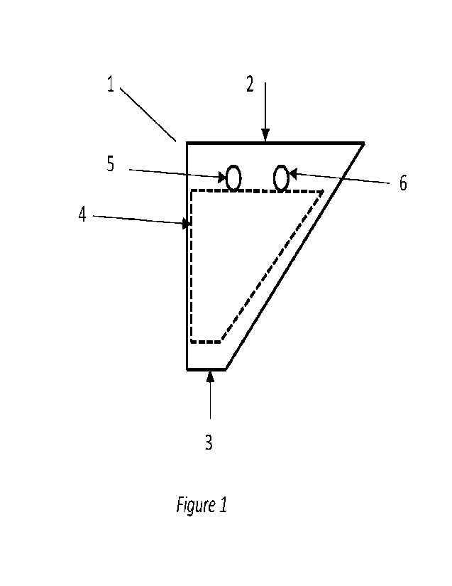
Figure 1 represents an embodiment of a hopper according to the present
disclosure viewed
from one side. The hopper 1 comprises a top end 2, a bottom end 3 a plurality,
for example between
30 and 40, of cooling plates 4 placed vertically and parallel to each other.
The cooling plates 4 are
made of stainless steel SS316L and are connected to an inlet pipe 5 for a
cooling liquid and an outlet
pipe 6 for the cooling liquid. The sides of a cooling plate are essentially
parallel to the corresponding
side of the hopper to optimize the surface area of the cooling plate. The top
end is about 3.8 m2 and
partially open to receive the particles. The bottom end is about 0.38 m2 and
is fully open, i.e. the
opening on the bottom end is 0.38 m2. The cooling liquid is process water
available in the plant. The
water has a temperature of 37 C at the inlet pipe of the hopper. The height
of the cooling plates 4 is
56% of the height of the hopper 1.
The hopper from figure 1 is part of a granulation unit comprising a fluidized
bed granulator, a
conveyor belt for transporting the oversize granules produced in the
granulator to the hopper, a
crusher, wherein the opening of the bottom end of the hopper is located
directly above the crusher,
and a conveyor belt for transporting the crushed granules obtained from the
crusher to an inlet of
the granulator. A screen is placed between an outlet for the oversized
granules of the granulator and
the conveyor belt to transport the oversize granules to the hopper and has a
mesh size of 10 mm.
The distance between two cooling plates 4 in the hopper is about 50 mm. The
granules, for example
comprising urea, have a temperature of 60 to 75 C when they arrive at the
hopper, and a
temperature of 40 to 45 C when they are dispensed from the hopper to the
crusher.
Figure 2 represents another view of the same embodiment as Figure 1, i.e.
after a rotation of
90 around a vertical axis. The hopper comprises a plurality of cooling
plates 4 essentially vertical
and parallel to each other, and connected to the inlet pipe 5. The outlet pipe
6 is located in the same
horizontal plane as the inlet pipe 5.
CA 03205096 2023-7- 13