Note: Descriptions are shown in the official language in which they were submitted.
CA 03205233 2023-06-14
WO 2022/133270 PCT/US2021/064130
SYSTEMS AND METHODS FOR EVALUATING ELECTRICAL PHASORS TO
IDENTIFY, ASSESS, AND MITIGATE POWER QUALITY ISSUES
CROSS REFERENCE TO RELATED APPLICATION
[0001] This application claims the benefit of and priority to U.S. Provisional
Application
No. 63/127,302, filed on December 18, 2020, which application was filed under
35 U.S.C.
119(e) and is incorporated by reference herein in its entirety.
FIELD
[0002] This disclosure relates generally to power quality issues, and more
particularly,
to systems and methods for evaluating electrical phasors to identify, assess,
and
mitigate power quality issues.
BACKGROUND
[0003] As is known, power quality issues/events are one of the most
significant and
costly impacts on electrical systems (also sometimes referred to as
"electrical
networks"). Poor power quality is estimated to cost the European economy up to
Ã150
billion annually, according to the Leonardo Power Quality Initiative.'
Additionally, the
U.S. economy experiences losses ranging from $119 billion to $188 billion
annually,
according to research by the Electric Power Research Institute (EPRI).2
Perhaps the most
important statistic is the EPRI finding that 80 percent of power-quality
disturbances are
generated within a facility. One exemplary economic model summarizes the total
cost
associated with power quality events as follows:
Total losses = production losses + restart losses + product/material losses +
equipment losses + third-party costs + other miscellaneous costs3
1 h ttps://adf power Lunin.g, conVertiabo IJ t-usin ?:NS-S tc3ries1148-
leonardo-ener.gy-apan-european-power-
ualit..-surve iv-shows- =150bn-annuall--in-cost-for-low-power-, ualit ..htrni
2 htt s:liblo .schneider-elec:tric.comlbower-rnanaa.ernE.Int-meterin =-
monitorin -.-bower-
qualltv/2015/10/1.61vvhv.-noor-inoweralitt-costs-billons-arnually-and.-what-
can-bi?-done-sbout-ii.i
'The Cost of Poor Power Quality, Roman Targosz and David Chapman, October
2015, ECI Publication No.
Cu0145
1
CA 03205233 2023-06-14
WO 2022/133270 PCT/US2021/064130
[0004] Other miscellaneous costs associated with power quality issues may
include
intangible losses such as a damaged reputation with customers and suppliers or
more
direct losses such as the devaluation of credit ratings and stock prices.
SUMMARY
[0005] Described herein are new and innovative assessment techniques for
evaluating
electrical phasors to identify, assess and mitigate power quality issues. The
power
quality issues may include short-duration root mean square (rms) variations
and voltage
transients (generally referred to herein as "transient overvoltage events"),
for example.
[0006] As is known, transient overvoltage events, for example, can originate
inside an
energy consumer's facility or out on the utility's grid, often propagating
through various
levels of electrical and data systems. Sources of destructive transient
overvoltage
events can range from the obvious, such as a lightning strike during a
thunderstorm, to
the subtle, such as static discharge from a human finger. Studies have
suggested that
sixty percent or more of all transient overvoltage events originate inside a
facility with
the remainder originating from outside sources, including lightning events and
switching
transient events originating on the utility system.
[0007] Transient overvoltage events that exceed insulation ratings can stress
electrical
insulation, leading to gradual breakdown or abrupt failure of the dielectric.
Some
industrial facilities, for example, may experience thousands of transient
overvoltage
events per hour with voltage impulses exceeding five to ten times the nominal
system
voltage in certain cases. Reducing the magnitude and duration of transient
overvoltage
events can extend the life of equipment insulation (e.g., in these industrial
facilities),
resulting in longer equipment operational life.
[0008] Transient overvoltage events typically last from less than a
microsecond to
several milliseconds, and are generally classified into one of two different
subcategories:
2
CA 03205233 2023-06-14
WO 2022/133270 PCT/US2021/064130
impulsive or oscillatory. Because damage due to transient overvoltage events
may not
be obvious, resulting failures are often diagnosed as "unknown cause." Studies
have
shown that up to seventy-five percent of integrated circuit failures may be
due to
transient overvoltage events. Furthermore, it has been estimated that billions
of dollars
in electronic equipment losses occur globally each year due to transient
overvoltage
events, with these numbers increasing each year as technology evolves.
[0009] Because of their prevalence and influence on electrical systems,
providing a firm
understanding of the exposure to short-duration rms variations and transient
overvoltage events is essential, especially for facilities with sensitive or
susceptible loads
and processes. To address this and other needs, the invention disclosed herein
provides
new and innovative assessment techniques for evaluating electrical phasors to
identify,
assess and mitigate power quality issues, including short-duration rms
variations and
transient overvoltage events.
[0010] A method in accordance with one embodiment of this disclosure includes
capturing, measuring or deriving at least one energy-related signal using one
or more
intelligent electronic devices (IEDs) in an electrical system, and processing
electrical
measurement data from, or derived from, the at least one energy-related signal
to
identify anomalous characteristics in the electrical system. In response to
identifying the
anomalous characteristics in the electrical system, a degree of voltage phase
jump and a
voltage sag magnitude (e.g., an indication of the voltage sag's depth) may be
determined based on or using the identified anomalous characteristics. The
degree of
the voltage phase jump and the voltage sag magnitude may be
presented/displayed on
at least one phasor diagram, and the at least one phasor diagram may be
analyzed to
determine most optimal/cost-effective apparatus(es) to mitigate at least one
of the
identified anomalous characteristics. One or more actions may be taken or
performed
based on determining the most optimal/cost-effective apparatus(es) to mitigate
the at
least one of the identified anomalous characteristics.
3
CA 03205233 2023-06-14
WO 2022/133270 PCT/US2021/064130
[0011] In accordance with some embodiments of this disclosure, the degree of
the
voltage phase jump and the voltage sag magnitude are each represented by at
least one
indication on the at least one phasor diagram. The at least one indication may
take the
form of at least one of: a phasor, a shape, a marker, a shading, a coloring, a
heat map, a
sound indicator, and an icon, for example, with the at least one indicator
being
representative of the degree of the voltage phase jump and the voltage sag
magnitude.
In accordance with some embodiments of this disclosure, characteristics
associated with
the phasor, the shape, the marker, the shading, the coloring, the heat map,
the sound
indicator, and the icon are manually or automatically configured.
[0012] In accordance with some embodiments of this disclosure, the method
further
includes determining a duration of the identified anomalous characteristics,
and
displaying the duration of the identified anomalous characteristics on the at
least one
phasor diagram. In accordance with some embodiments of this disclosure,
information
relating to at least one of: the degree of voltage phase jump, the voltage sag
magnitude,
and the duration of the identified anomalous characteristics presented on the
at least
one phasor diagram is analyzed to determine the most optimal/cost-effective
apparatus(es) to mitigate at least one of the identified anomalous
characteristics.
[0013] In accordance with some embodiments of this disclosure, the one or more
actions taken or performed based on determining the most optimal/cost-
effective
apparatus(es) to mitigate the at least one of the identified anomalous
characteristics,
include: overlaying one or more mitigative solution characteristics on one or
more
phasor diagrams of the at least one phasor diagram. In accordance with some
embodiments of this disclosure, the one or more mitigative solution
characteristics are
indicated using at least one of: a shape, a marker, a shading, a coloring, a
heat map, a
sound indicator, and an icon, with the at least one indicator being
representative of the
one or more mitigative solution characteristics. The one or more mitigative
solution
characteristics overlayed on the one or more phasor diagrams may be
associated, for
4
CA 03205233 2023-06-14
WO 2022/133270 PCT/US2021/064130
example, with at least one range or zone where the one or more mitigative
solution
characteristics are determined to be capable of successfully mitigating at
least one
anomalous condition of the identified anomalous conditions within the at least
one
range or zone. In accordance with some embodiments of this disclosure, the one
or
more mitigative solution characteristics include capability to resolve or
mitigate at least
one of: the voltage phase jump, the voltage sag magnitude and a duration of
the
identified anomalous characteristics (e.g., as shown by a marker or other form
of
indication). In some embodiments, recurrent anomalous characteristics may be
indicated on one or more phasor diagrams of the at least one phasor diagram.
It is
understood that a variety of information may be presented on the above and
below
described at least one phasor diagram, including information relating the
mitigative
solution characteristics and information relating to the identified anomalous
characteristics (e.g., degree of phase jump, voltage sag magnitude and
duration of the
identified anomalous characteristics). These types of information may each be
shown by
one or more indications including, for example, a shape, a marker, a shading,
a coloring,
a heat map, a sound indicator, and an icon.
[0014] In accordance with some embodiments of this disclosure, the at least
one phasor
diagram presented/displayed includes at least one of: information relating to
the most
optimal/cost-effective apparatus(es) of analyzed mitigative apparatus(es) to
mitigate the
at least one of the identified anomalous characteristics, and information
relating to the
identified anomalous characteristics. In accordance with some embodiments of
this
disclosure, the information relating to the identified anomalous
characteristics including
at least one of: degree of phase jump, voltage sag magnitude and duration of
the
identified anomalous characteristics. In accordance with some embodiments of
this
disclosure, the information relating to the most optimal/cost-effective
apparatus(es) of
analyzed mitigative apparatus(es) to mitigate the at least one of the
identified
anomalous characteristics, and the information relating to the identified
anomalous
characteristics, is shown by one or more indications. In accordance with some
CA 03205233 2023-06-14
WO 2022/133270 PCT/US2021/064130
embodiments of this disclosure, the one or more indications including at least
one of: a
shape, a marker, a shading, a coloring, a heat map, a sound indicator, and an
icon.
[0015] In accordance with some embodiments of this disclosure, the identified
anomalous characteristics are indicative of at least one power quality issue
in the
electrical system. In accordance with some embodiments of this disclosure, the
at least
one power quality issue is identified based on an analysis of at least one of:
the degree
of voltage phase jump, the voltage sag magnitude, and the duration of the
identified
anomalous characteristics (e.g., as presented/displayed on the at least one
phasor
diagram). In accordance with some embodiments of this disclosure, the at least
one
power quality issue includes at least one voltage event. The at least one
voltage event
may include, for example, at least one of: a voltage sag, a voltage swell, a
transient
overvoltage event, a short-duration rms variation, and a long-duration rms
variation.
[0016] As is known, anomalous characteristics/conditions (e.g., the identified
anomalous conditions) may produce or lead to stresses (e.g., electrical,
thermal and
mechanical) that may shorten the life of equipment in an electrical system.
Therefore, it
is desirable to detect the anomalous characteristics/conditions and reduce the
effects of
the anomalous characteristics/conditions in response to detecting the
anomalous
characteristics/conditions (e.g., to extend the operational life of the
equipment). It is
important to note that a specific device and/or technique may be capable of
adequately/sufficiently mitigating one or more specific anomalous
characteristics/conditions; however, not capable of mitigating other anomalous
characteristics/conditions. To address this and other concerns, the above-
discussed
method may analyze the generated at least one phasor diagram to analyze at
least one
voltage event (or anomalous event) to determine the most optimal/cost-
effective
apparatus(es) to mitigate at least one of the identified anomalous
characteristics, and
take one or more actions based on determining the most optimal/cost-effective
apparatus(es) to mitigate the at least one of the identified anomalous
characteristics. In
accordance with some embodiments of this disclosure, the one or more actions
may be
automatically taken/performed by a control system (e.g., a diagnostic control
system)
6
CA 03205233 2023-06-14
WO 2022/133270 PCT/US2021/064130
associated with the electrical system. In accordance with some embodiments of
this
disclosure, the control system is communicatively coupled to the one or more
IEDs
responsible for capturing the at least one energy-related signal, and/or to a
cloud-based
system, on-site/edge software, a gateway, and other head-end system associated
with
the electrical system.
[0017] In some embodiments, the above method (and/or the other systems and
methods disclosed herein) may use one or more of the above and below discussed
features. For example, features of one or more of the above and below
discussed
example implementations of the inventions disclosed herein may be combined
with or
substituted by one or more other of the above and below discussed example
implementations of the inventions disclosed herein. Additionally, in some
embodiments
the above method (and/or the other systems and methods disclosed herein) may
be
implemented on or using at least one IED, for example, on the one or more IEDs
responsible for capturing or deriving the energy-related signals.
Additionally, in some
embodiments the above method (and/or the other systems and methods disclosed
herein) may be implemented partially or fully remote from the one or more
IEDs, for
example, in a cloud-based system, on-site/edge software, a gateway, and other
head-
end system associated with the electrical system. Examples of the one or more
IEDs
may include a smart utility meter, a digital power quality meter, and/or
another
measurement device (or devices). The one or more IEDs may include breakers,
relays,
power quality correction devices, uninterruptible power supplies (UPSs),
filters, and/or
variable speed drives (VSDs), for example. Additionally, the one or more IEDs
may
include at least one virtual meter in some embodiments.
[0018] It is understood that the energy-related signals captured or derived by
the one or
more IEDs discussed above may include, for example, at least one of: a voltage
signal, a
current signal, input/output (I/O) data, and a derived or extracted value. In
some
embodiments, the I/O data includes at least one of a digital signal (e.g., two
discrete
states) and an analog signal (e.g., continuously variable). The digital signal
may include,
7
CA 03205233 2023-06-14
WO 2022/133270 PCT/US2021/064130
for example, at least one of on/off status(es), open/closed status(es),
high/low
status(es), synchronizing pulse and any other representative bi-stable signal.
Additionally, the analog signal may include, for example, at least one of
temperature,
pressure, volume, spatial, rate, humidity, and any other physically or
user/usage
representative signal.
[0019] In accordance with some embodiments of this disclosure, the derived or
extracted value includes at least one of a calculated, computed, estimated,
derived,
developed, interpolated, extrapolated, evaluated, and otherwise determined
additional
energy-related value from at least one of the measured voltage signal and/or
the
measured current signal. In some embodiments, the derived value additionally
or
alternatively includes at least one of active power(s), apparent power(s),
reactive
power(s), energy(ies), harmonic distortion(s), power factor(s),
magnitude/direction of
harmonic power(s), harmonic voltage(s), harmonic current(s), interharmonic
current(s),
interharmonic voltage(s), magnitude/direction of interharmonic power(s),
magnitude/direction of sub-harmonic power(s), individual phase current(s),
phase
angle(s), impedance(s), sequence component(s), total voltage harmonic
distortion(s),
total current harmonic distortion(s), three-phase current(s), phase
voltage(s), line
voltage(s), spectral analysis and/or other similar/related parameters. In some
embodiments, the derived value additionally or alternatively includes at least
one
energy-related characteristic, the energy-related characteristic including
magnitude,
direction, phase angle, percentage, ratio, level, duration, associated
frequency
components, energy-related parameter shape, and/or decay rate. In accordance
with
some embodiments of this disclosure, the derived or extracted value may be
linked to at
least one process, load(s) identification, etc., for example.
[0020] It is understood that the at least one energy-related signal or
waveform
captured or derived by one or more IEDs may include (or leverage)
substantially any
electrical parameter derived from at least one of a voltage and current signal
(including
the voltages and currents themselves), for example. It is also understood that
the at
8
CA 03205233 2023-06-14
WO 2022/133270 PCT/US2021/064130
least one energy-related signal or waveform may be continuously or semi-
continuously/periodically captured/recorded and/or transmitted and/or logged
by the
one or more IEDs, and power quality issues/events may be detected/identified
based on
the at least one energy-related signal.
[0021] A system to automatically identify power quality issues from at least
one energy-
related signal in an electrical system is also provided herein. In one aspect
of this
disclosure, the system includes at least one processor and at least one memory
device
(e.g., local and/or remote memory device) coupled to the at least one
processor. The at
least one processor and the at least one memory device are configured to
capture or
derive at least one energy-related signal using one or more IEDs in the
electrical system,
and process electrical measurement data from, or derived from, the at least
one energy-
related signal to identify anomalous characteristics in the electrical system.
In response
to identifying the anomalous characteristics in the electrical system, a
degree of voltage
phase jump and a voltage sag magnitude may be determined based on or using the
identified anomalous characteristics. The degree of the voltage phase jump and
the
voltage sag magnitude may be presented/displayed on at least one phasor
diagram, and
the at least one phasor diagram may be analyzed to determine most optimal/cost-
effective apparatus(es) to mitigate at least one of the identified anomalous
characteristics. One or more actions may be taken or performed based on
determining
the most optimal/cost-effective apparatus(es) to mitigate the at least one of
the
identified anomalous characteristics.
[0022] In accordance with some embodiments of this disclosure, the at least
one
processor and the at least one memory device of the system are further
configured to
determine a duration of the identified anomalous characteristics, and display
the
duration of the identified anomalous characteristics on the at least one
phasor diagram.
In accordance with some embodiments of this disclosure, information relating
to at least
one of: the degree of voltage phase jump, the voltage sag magnitude, and the
duration
of the identified anomalous characteristics presented on the at least one
phasor
9
CA 03205233 2023-06-14
WO 2022/133270
PCT/US2021/064130
diagram is analyzed to determine the most optimal/cost-effective apparatus(es)
to
mitigate at least one of the identified anomalous characteristics.
[0023] In accordance with some embodiments of this disclosure, the one or more
actions taken or performed based on determining the most optimal/cost-
effective
apparatus(es) to mitigate the at least one of the identified anomalous
characteristics,
include: overlaying one or more mitigative solution characteristics on one or
more
phasor diagrams of the at least one phasor diagram. In accordance with some
embodiments of this disclosure, the one or more mitigative solution
characteristics are
indicated using at least one of: a shape, a marker, a shading, a coloring, a
heat map, a
sound indicator, and an icon, with the at least one indicator being
representative of the
one or more mitigative solution characteristics. The one or more mitigative
solution
characteristics overlayed on the one or more phasor diagrams may be
associated, for
example, with at least one range or zone where the one or more mitigative
solution
characteristics are determined to be capable of successfully mitigating at
least one
anomalous condition of the identified anomalous conditions within the at least
one
range or zone. In accordance with some embodiments of this disclosure, the one
or
more mitigative solution characteristics include capability to resolve or
mitigate at least
one of: the voltage phase jump, the voltage sag magnitude and a duration of
the
identified anomalous characteristics. In some embodiments, recurrent anomalous
characteristics may be indicated on one or more phasor diagrams of the at
least one
phasor diagram. It is understood that a variety of information may be
presented on the
above and below described at least one phasor diagram, including information
relating
the mitigative solution characteristics and information relating to the
identified
anomalous characteristics (e.g., degree of phase jump, voltage sag magnitude
and
duration of the identified anomalous characteristics). These types of
information may
each be shown by one or more indications including, for example, a shape, a
marker, a
shading, a coloring, a heat map, a sound indicator, and an icon.
CA 03205233 2023-06-14
WO 2022/133270 PCT/US2021/064130
[0024] In accordance with some embodiments of this disclosure, the at least
one phasor
diagram presented/displayed includes at least one of: information relating to
the most
optimal/cost-effective apparatus(es) of analyzed mitigative apparatus(es) to
mitigate the
at least one of the identified anomalous characteristics, and information
relating to the
identified anomalous characteristics. In accordance with some embodiments of
this
disclosure, the information relating to the identified anomalous
characteristics including
at least one of: degree of phase jump, voltage sag magnitude and duration of
the
identified anomalous characteristics. In accordance with some embodiments of
this
disclosure, the information relating to the most optimal/cost-effective
apparatus(es) of
analyzed mitigative apparatus(es) to mitigate the at least one of the
identified
anomalous characteristics, and the information relating to the identified
anomalous
characteristics, is shown by one or more indications. In accordance with some
embodiments of this disclosure, the one or more indications including at least
one of: a
shape, a marker, a shading, a coloring, a heat map, a sound indicator, and an
icon.
[0025] In accordance with some embodiments of this disclosure, the above-
discussed
system includes or is coupled to at least one control device or system (e.g.,
a diagnostic
control device or system). In accordance with some embodiments of this
disclosure, the
at least one control device or system is configured to take or perform the
above-
discussed one or more actions based on determining the most optimal/cost-
effective
apparatus(es) to mitigate the at least one of the identified anomalous
characteristics
(e.g., in response to receiving one or more control signals from the above-
discussed
system or portions/select circuitry of the system).
[0026] In some embodiments, the one or more IEDs capturing or deriving the at
least
one energy-related signal include at least one metering device. The at least
one
metering device may correspond, for example, to at least one metering device
in the
electrical system for which the energy-related signals are being
captured/monitored.
11
CA 03205233 2023-06-14
WO 2022/133270 PCT/US2021/064130
[0027] As used herein, an IED is a computational electronic device optimized
to
perform a particular function or set of functions. Examples of IEDs may
include smart
utility meters, power quality meters, microprocessor relays, digital fault
recorders, and
other metering devices. IEDs may also be imbedded in VSDs, uninterruptible
power
supplies (UPSs), circuit breakers, relays, transformers, or any other
electrical apparatus.
IEDs may be used to perform measurement/monitoring and control functions in a
wide
variety of installations. The installations may include utility systems,
industrial facilities,
warehouses, office buildings or other commercial complexes, campus facilities,
computing co-location centers, data centers, power distribution networks, or
any other
structure, process or load that uses electrical energy. For example, where the
IED is an
electrical power monitoring device, it may be coupled to (or be installed in)
an electrical
power transmission or distribution system and configured to sense/measure and
store
data (e.g., waveform data, logged data, I/O data, etc.) as electrical
parameters
representing operating characteristics (e.g., voltage, current, waveform
distortion,
power, etc.) of the electrical distribution system. These parameters and
characteristics
may be analyzed by a user to evaluate potential performance, reliability
and/or power
quality-related issues, for example. The IED may include at least a controller
(which in
certain IEDs can be configured to run one or more applications simultaneously,
serially,
or both), firmware, a memory, a communications interface, and connectors that
connect
the IED to external systems, devices, and/or components at any voltage level,
configuration, and/or type (e.g., AC, DC). At least certain aspects of the
monitoring and
control functionality of an IED may be embodied in a computer program that is
accessible by the IED.
[0028] In some embodiments, the term "IED" as used herein may refer to a
hierarchy of
IEDs operating in parallel and/or tandem/series. For example, an IED may
correspond to
a hierarchy of energy meters, power meters, and/or other types of resource
meters.
The hierarchy may comprise a tree-based hierarchy, such a binary tree, a tree
having
one or more child nodes descending from each parent node or nodes, or
combinations
thereof, wherein each node represents a specific IED. In some instances, the
hierarchy
12
CA 03205233 2023-06-14
WO 2022/133270 PCT/US2021/064130
of IEDs may share data or hardware resources and may execute shared software.
It is
understood that hierarchies may be non-spatial such as billing hierarchies
where IEDs
grouped together may be physically unrelated.
[0029] It is understood that an input is data that a processor and/or IED
(e.g., the
above-discussed one or more IEDs) receives, and an output is data that a
processor
and/or IED sends. Inputs and outputs may either be digital or analog. The
digital and
analog signals may be both discrete variables (e.g., two states such as
high/low,
one/zero, on/off, etc. If digital this may be a value. If analog, the presence
of a
voltage/current may be considered by the system/IED as an equivalent signal)
or
continuous variables (e.g., continuously variable such as spatial position,
temperature,
pressure voltage, etc.). They may be digital signals (e.g., measurements in an
IED
coming from a sensor producing digital information/values) and/or analog
signals (e.g.,
measurements in an IED coming from a sensor producing analog
information/values).
These digital and/or analog signals may include any processing step within the
IED (e.g.,
derive a Power Factor, a magnitude, among all the derived calculations).
[0030] Processors and/or IEDs may convert/reconvert digital and analog input
signals to
a digital representation for internal processing. Processors and/or IEDs may
also be
used to convert/reconvert internally processed digital signals to digital
and/or analog
output signals to provide some indication, action, or other response (such as
an input for
another processor/IED). Typical uses of digital outputs may include opening or
closing
breakers or switches, starting or stopping motors and/or other equipment, and
operating other devices and equipment that are able to directly interface with
digital
signals. Digital inputs are often used to determine the operational
status/position of
equipment (e.g., is a breaker open or closed, etc.) or read an input
synchronous signal
from a utility pulsed output. Analog outputs may be used to provide variable
control of
valves, motors, heaters, or other loads/processes in energy management
systems.
Finally, analog inputs may be used to gather variable operational data and/or
in
proportional control schemes.
13
CA 03205233 2023-06-14
WO 2022/133270 PCT/US2021/064130
[0031] A few more examples where digital and analog I/O data are leveraged may
include (but not be limited to): turbine controls, plating equipment,
fermenting
equipment, chemical processing equipment, telecommunications, equipment,
precision
scaling equipment, elevators and moving sidewalks, compression equipment,
waste
water treatment equipment, sorting and handling equipment, plating equipment
temperature/pressure data logging, electrical
generation/transmission/distribution,
robotics, alarm monitoring and control equipment, as a few examples.
[0032] As noted earlier in this disclosure, the at least one energy-related
signal
captured or derived by the one or more IEDs may include I/O data. It is
understood that
the I/O data may take the form of digital I/O data, analog I/O data, or a
combination
digital and analog I/O data. The I/O data may convey status information, for
example,
and many other types of information, as will be apparent to one of ordinary
skill in the
art from discussions above and below.
[0033] It is understood that the terms "processor" and "controller" are
sometimes used
interchangeably herein. For example, a processor may be used to describe a
controller.
Additionally, a controller may be used to describe a processor.
[0034] Techniques relating to phasor analysis for transient overvoltage events
are also
disclosed herein. In accordance with some embodiments of this disclosure, the
phasor
analysis provides/enables an assessment of effects of motor regeneration
characteristics
or conditions in an electrical system. In one aspect, a method for
providing/enabling
this assessment includes capturing or deriving at least one energy-related
signal using
one or more IEDs in the electrical system, and processing electrical
measurement data
from, or derived from, the at least one energy-related signal to identify at
least one of:
regenerative characteristics or conditions associated with at least one
working/operational motor (e.g., an induction motor) in the electrical system,
and a
switching event(s)/action(s) producing a switching transient in the electrical
system. The
14
CA 03205233 2023-06-14
WO 2022/133270 PCT/US2021/064130
identified regenerative characteristics or conditions and/or the switching
event(s)/action(s) from the electrical measurement data may be analyzed to
determine
if the at least one operational motor is exposed to damage(s)/stress(es)
(e.g., electrical
and/or mechanical stress(es)) from the identified regenerative characteristics
or
conditions and/or the switching event(s)/action(s). In response to determining
the at
least one operational motor is exposed to damage(s)/stress(es) from the
identified
regenerative characteristics or conditions and/or the switching
event(s)/action(s), one or
more actions may be taken or performed to reduce or eliminate at least one of:
the
damage(s)/stress(es) to the at least one operational motor and the
damage(s)/stress(es)
to other components in the electrical system from the identified regenerative
characteristics or conditions and/or the switching event(s)/action(s).
[0035] In accordance with some embodiments of this disclosure, the one or more
IEDs
responsible for capturing the at least one energy-related signal are located
proximate to
the at least one operational motor for which the regenerative characteristics
or
conditions are identified in the electrical system, and/or to the switching
event(s)/action(s) producing a switching transient in the electrical system.
Additionally,
in accordance with some embodiments of this disclosure, the method further
includes
analyzing the identified regenerative characteristics or conditions and/or the
switching
event(s)/action(s) from the electrical measurement data to determine power
quality
issues caused by the at least one operational motor. In accordance with some
embodiments of this disclosure, the regenerative characteristics or conditions
are
caused by an energy source being disconnected from the at least one
operational motor.
[0036] In accordance with some embodiments of this disclosure, the one or more
actions taken/performed using the aforesaid method include identifying at
least one
means to mitigate or eliminate at least one of: the damage(s)/stress(es) to
the at least
one operational motor and the damage(s)/stress(es)damage(s)/stress(es) to
other
components in the electrical system, selecting one or more of the at least one
mitigation
or elimination means based on priority and/or severity of: the
damage(s)/stresses to the
CA 03205233 2023-06-14
WO 2022/133270 PCT/US2021/064130
at least one operational motor and/or the damage(s)/stresses to other
components, and
at least one of indicating and applying the selected one or more of the at
least one
mitigation or elimination means. The selected one or more of the at least one
mitigation or elimination means may be indicated, for example, on at least one
plot, the
at least one plot indicating at least one of: a point or points where re-
energization
occurred with respect to the phase angle, and the selected one or more of the
at least
one mitigation or elimination means. In accordance with some embodiments of
this
disclosure, the one or more of the at least one mitigation or elimination
means is further
selected based on an expected ability of the one or more of the at least one
mitigation
or elimination means to reduce or eliminate at least one of magnitude and
duration of
potentially damaging conditions (e.g., from energy-related transients, such as
switching
transients) in the electrical system. Additionally, in accordance with some
embodiments
of this disclosure, the one or more of the at least one mitigation or
elimination means is
further selected based on costs (e.g., economic costs) associated with
acquiring and/or
applying the one or more of the at least one mitigation or elimination means.
[0037] In accordance with some embodiments of this disclosure, the
regenerative
characteristics or conditions associated with at least one operational motor
in the
electrical system are determined to be due to a switching transient(s) in the
electrical
system, and the one or more of the at least one mitigation or elimination
means
includes at least one transient mitigative device. The at least one transient
mitigative
device may include, for example, at least one of: a surge arrester, a
lightning arrestor, a
surge suppressor, transient voltage surge suppressor, line reactor,
regenerative load
bank, and an isolation transformer.
[0038] In accordance with some embodiments of this disclosure, the one or more
actions are automatically performed by a control system (e.g., a diagnostic
control
system) associated with the electrical system. The control system may be
communicatively coupled to the one or more IEDs responsible for capturing or
deriving
the at least one energy-related signal, and/or to a cloud-based system, on-
site/edge
16
CA 03205233 2023-06-14
WO 2022/133270 PCT/US2021/064130
software, a gateway, and other head-end system associated with the electrical
system,
for example.
[0039] In accordance with some embodiments of this disclosure, the other
components
in the electrical system for which the damage(s)/stress(es) are evaluated are
adjacently
connected to the at least one operational motor for which the regenerative
characteristics or conditions are identified.
[0040] A corresponding system to the above method for using electrical phasors
to
analyze/assess effects of motor regeneration characteristics or conditions in
an electrical
system is also provided herein. It is understood that the phasor analysis may
be applied
to other equipment/devices besides motors, as will be appreciated by one of
ordinary
skill in the art.
[0041] Other example aspects, features and advantages of the disclosed
invention will
be appreciated from the discussions below.
BRIEF DESCRIPTION OF THE DRAWINGS
[0042] The foregoing features of the disclosure, as well as the disclosure
itself may be
more fully understood from the following detailed description of the drawings,
in which:
[0043] Figure 1 shows a graphical view of several example power quality
categories;
[0044] Figure 2 illustrates an example of a downstream fault on a utility
distribution
feeder;
[0045] Figure 3 shows an example electrical system in accordance with
embodiments of
the disclosure;
[0046] Figure 3A shows an example Intelligent Electronic Device (IED) that may
be used
in an electrical system in accordance with embodiments of the disclosure;
17
CA 03205233 2023-06-14
WO 2022/133270
PCT/US2021/064130
[0047] Figure 3B shows an example configuration of IEDs in accordance with
embodiments of the disclosure;
[0048] Figure 4 shows an example Information Technology Industry (ITI) curve
(also
sometimes referred to as an ITIC curve, CBEMA curve, or a "power acceptability
curve");
[0049] Figure 5 shows example root mean square (rms) alarm thresholds in
accordance
with embodiments of the disclosure;
[0050] Figure 6 shows an example instantaneous waveform capture of an
illustrative
voltage event in accordance with embodiments of the disclosure;
[0051] Figure 7 shows example rms voltage for the illustrative voltage event
of Figure 6
in accordance with embodiments of the disclosure;
[0052] Figure 8 shows example rms real power for the illustrative voltage
event of
Figure 6 in accordance with embodiments of the disclosure;
[0053] Figure 9 shows an example instantaneous waveform capture of another
illustrative voltage event in accordance with embodiments of the disclosure;
[0054] Figure 10 shows example rms voltage for the illustrative voltage event
of Figure
9 in accordance with embodiments of the disclosure;
[0055] Figure 11 shows example rms real power for the illustrative voltage
event of
Figure 9 in accordance with embodiments of the disclosure;
[0056] Figure 12 shows an example instantaneous waveform capture of another
illustrative voltage event in accordance with embodiments of the disclosure;
18
CA 03205233 2023-06-14
WO 2022/133270
PCT/US2021/064130
[0057] Figure 13 shows example rms voltage for the illustrative voltage event
of Figure
12 in accordance with embodiments of the disclosure;
[0058] Figure 14 shows example rms real power for the illustrative voltage
event of
Figure 12 in accordance with embodiments of the disclosure;
[0059] Figure 15 shows example waveforms without phase jump and its phase jump
phasor diagrams for an example voltage event in accordance with embodiments of
this
disclosure;
[0060] Figure 16 shows example waveforms with phase jump waveforms and its
phase
jump phasor diagrams for another example voltage event in accordance with
embodiments of this disclosure;
[0061] Figure 17 shows an example phase jump plot of multiple discrete events
in
accordance with embodiments of this disclosure;
[0062] Figure 18 shows an example phase jump plot of multiple discrete events
with
impact indications in accordance with embodiments of this disclosure;
[0063] Figure 19A shows an example phase jump plot of multiple discrete events
with
impact indications and mitigation overlays in accordance with embodiments of
this
disclosure;
[0064] Figure 19E3 shows an example phase jump plot of multiple discrete
voltage sag
events with impact indications, mitigation overlays, and duration lines in
accordance
with embodiments of this disclosure;
19
CA 03205233 2023-06-14
WO 2022/133270 PCT/US2021/064130
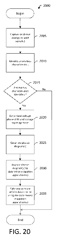
[0065] Figure 20 is a flowchart illustrating an example implementation of a
method to
automatically identify, assess and mitigate power quality issues using
electrical phasors
in accordance with embodiments of this disclosure;
[0066] Figure 21 provides an illustration of the voltage on one phase of a
motor when
the motor is energized/started;
[0067] Figure 21A provides an illustration of the current on one phase of a
motor when
the motor is energized/started. It is the current waveform associated with the
voltage
signal shown in Figure 21;
[0068] Figure 22 provides an illustration of the single-phase voltage on a
motor being
disconnected from its voltage source and resulting in a regenerative voltage;
[0069] Figure 22A provides an illustration of the single-phase voltage on a
motor being
disconnected from its voltage source and then reconnected back to its original
voltage
source, causing a switching transient;
[0070] Figure 23 is a real example of motor regeneration on a three-phase
electrical
system at an example data center;
[0071] Figure 24 is a simple model of an induction motor;
[0072] Figure 25 provides a simple circuit to illustrate the cause and
interactions of
motor regeneration in an electrical system;
[0073] Figure 26 illustrates the phasor relationship between the source
voltage, Vs, and
the motor's internally generated voltage, VI;
CA 03205233 2023-06-14
WO 2022/133270
PCT/US2021/064130
[0074] Figure 26A illustrates the phase angle relationship between one phase
of the
source voltage and the respective phase on the motor's internally generated
voltage
(i.e., from the rotor's magnetic field) at the instant the motor is
disconnected from its
source voltage;
[0075] Figure 26B illustrates the change in the phase angle relationship
between the
source voltage and the motor's internally generated voltage (i.e., from the
rotor's
magnetic field) as the rotor slows down after being disconnected;
[0076] Figure 26C highlights the area of potential damage (using a 110%
threshold) in
the phasor diagram when reconnecting a motor to its source voltage;
[0077] Figure 26D highlights the area of potential damage (using a 125%
threshold) in
the phasor diagram when reconnecting a motor to its source voltage;
[0078] Figure 26E highlights switching transient occurrences over an arbitrary
time
period in the phasor diagram;
[0079] Figure 27 is a flow diagram illustrating an exemplary method for
analyzing
effects of motor regeneration characteristics or conditions in an electrical
system in
accordance with embodiments of this disclosure;
[0080] Figure 28 is a flow diagram illustrating an exemplary method for
identifying
switching events/actions with motor(s) in accordance with embodiments of this
disclosure;
[0081] Figure 29 is a flow diagram illustrating exemplary real-time
functionality for
switching events/actions in accordance with embodiments of this disclosure;
and
21
CA 03205233 2023-06-14
WO 2022/133270 PCT/US2021/064130
[0082] Figure 30 is a flow diagram illustrating an exemplary method for
capturing and
mitigating switching events/actions in accordance with embodiments of this
disclosure.
DETAILED DESCRIPTION
[0083] The features and other details of the concepts, systems, and techniques
sought
to be protected herein will now be more particularly described. It will be
understood
that any specific embodiments described herein are shown by way of
illustration and not
as limitations of the disclosure and the concepts described herein. Features
of the
subject matter described herein can be employed in various embodiments without
departing from the scope of the concepts sought to be protected.
[0084] For convenience, certain introductory concepts and terms used in the
specification (and adopted from IEEE Standard 1159-2019) are collected here.
Several of
these concepts and terms are graphically illustrated in Figure 1, for example,
which
highlights the event magnitude and duration for short-duration rms variations,
including
voltage sags/dips, swells, and brief interruptions (<1 minute). The nominal
operating
voltage in this figure ranges between 10% of the nominal rated voltage. It is
notable
that Figure 1 does not include all power quality categories such as waveform
distortion,
imbalance, voltage fluctuations, and power frequency deviations.
[0085] As used herein, the term "aperiodic event" is used to describe an
electrical
event that occurs non-cyclically, arbitrarily or without specific temporal
regularity. For
the sake of this disclosure, both short-duration root-mean-square (rms)
variations and
transients are considered to be aperiodic events (i.e., notching is treated as
a harmonic
phenomenon herein).
[0086] As used herein, the term "instantaneous interruption" is used to
describe a
deviation to 0-10% of the nominal value for a duration of 1/2 cycle to 30
cycles.
22
CA 03205233 2023-06-14
WO 2022/133270 PCT/US2021/064130
[0087] As used herein, the term "momentary interruption" is used to describe a
deviation to 0-10% of the nominal value for a duration of 30 cycles to 3
seconds.
[0088] As used herein, the term "phase jump" is used to describe the change in
voltage
phase angle during a voltage sag as compared to the phase angle of the voltage
before
the voltage sag. It is understood that the term "phase jump" may also be
referred to as
phase-angle jump, phase shift, or phase jump/shift. Phase jump can be
different for
each of the three phases in a polyphase system. (IEEE Standard 1409-2012,
"IEEE Guide
for Application of Power Electronics for Power Quality Improvement on
Distribution
Systems Rated 1 kV Through 38 kV")
[0089] As used herein, the term "sag" (of which a "voltage sag" is one
example) is used
to describe a deviation to 10-90% of the nominal value, for example, for a
duration of 1/2
cycle to 1 minute, as shown in FIG. 1.
[0090] As used herein, the term "short-duration rms variations" is used to
describe a
deviation from the nominal value with a duration of 1/2 cycle to 1 minute. Sub-
categories
of short-duration rms variations include instantaneous interruptions,
momentary
interruptions, temporary interruptions, sags and swells.
[0091] As used herein, the term "swell" is used to describe a deviation
greater than
110% of the nominal value, for example, for a duration of 1/2 cycle to 1
minute, as shown
in FIG. 1.
[0092] As used herein, the term "temporary interruption" is used to describe a
deviation to 0-10% of the nominal value for a duration of 3 seconds to 1
minute.
[0093] As used herein, the term "transient" is used to describe a deviation
from the
nominal value with a duration less than 1 cycle. Sub-categories of transients
include
impulsive (uni-direction polarity) and oscillatory (bi-directional polarity)
transients.
23
CA 03205233 2023-06-14
WO 2022/133270
PCT/US2021/064130
[0094] IEEE Standard 1159-2019, as briefly referenced above, lists seven
general
categories of power quality phenomena. Two of these categories (short-duration
rms
variations and transients) are considered to be a-periodic (e.g., not
regularly occurring).
Of these two categories, short-duration rms variations are the most disruptive
and have
the largest universal economic impact on energy consumers. Short-duration rms
variations include voltage sags/dips, swells, instantaneous interruptions,
momentary
interruptions and temporary interruptions. One study by Electric Power
Research
Institute (EPRI) estimates an average of 56 voltage sags are experienced by
industrial
customers each year. As the trend of industries becoming more dependent on sag-
sensitive equipment has increased, so has the impact of these events.
[0095] It is understood that IEEE Standard 1159-2019 is one standards body's
(IEEE in
this case) approach to defining/characterizing power quality events. It is
understood
there are other standards that define power quality categories/events as well,
such as
the International Electrotechnical Commission (IEC), American National
Standards
Institute (ANSI), etc., which may have different descriptions or power quality
event
types, characteristics, and terminology. In some embodiments, power quality
events
may be customized power quality events (e.g., defined by a user).
[0096] Short-duration rms variations, as defined by IEEE Standard 1159-2019
and other
sources, may include many subcategories, including sags, swells, interruptions
and so
forth. A primary cause of short-duration rms variations are electrical faults,
which can
originate from:
= Insulation failure/dielectric = Construction incidents
breakdowns
= Lightning and other overvoltage =
Physical sagging of overhead
events conductors
= Conductor aging = Wildlife
= Poor design = Pollution
= Inclement weather = Traffic
accidents
= Vegetation = Equipment failure
24
CA 03205233 2023-06-14
WO 2022/133270 PCT/US2021/064130
[0097] A leading source of short-duration rms variations are electrical
faults; hence, the
need (i.e., codes & standards, safety requirements, manufacturer requirements,
protection of equipment, and so forth) to provide protection from system
faults. Faults
(definition) generally lead to a short circuit condition (define), resulting
in significantly
reduced impedances, and thus, large current flows (i.e., due to Ohm's law).
Depending
on the location of a fault within an electrical system, faults can have
catastrophic effects
on the production and safe operation of a facility. The high current
associated with
faults produces heat that can damage equipment and insulation, result in
system
operational issues and affect system stability, lead to voltage sags and
interruptions,
cause fires, and produce safety hazards.
[0098] Rapid changes in the impedance due to electrical fault events can
produces very
fast deviations in the electrical system's characteristics. For example, the
system voltage
may abruptly decrease and phase shifts (phase jump) may occur. Significant
variations in
the voltage's magnitude can adversely impact connected equipment, causing it
to trip
offline or mis-operate.
[0099] All equipment is designed to operate within a prescribed voltage range.
For
example, a residential microwave oven may have a nominal voltage rating of 120
volts
while an electric oven adjacent to the microwave may have a nominal rating of
240
volts. Similarly, industrial equipment may use equipment designed for hundreds
of volts
(e.g., 120 volts) to thousands of volts (e.g., 4160 volts, 12.47 kV, etc.). As
the voltage to
a particular piece of equipment deviates from its expected nominal value, the
equipment may exhibit a range of problems/issues such as de-energization,
erratic
operation, or even damage.
[0100] By definition, a voltage sag (dip) is an unexpected excursion of the
normal
operating voltage to 10-90% of the nominal rated voltage lasting less than one
minute.
Figure 2 illustrates an example of a downstream fault (here, a phase-to-phase
fault) on a
utility distribution feeder. As shown in this figure, the downstream fault
causes large
CA 03205233 2023-06-14
WO 2022/133270 PCT/US2021/064130
current flow and a voltage sag/dip on the two phases. The degree of impact
this type of
event has on an energy consumer's facility is primarily dependent on the four
factors:
1. The nature and source of the event,
2. The susceptibility of the load(s) to the event,
3. The event's influence on the process or activity, and
4. The cost sensitivity to this effect.
[0101] Consequently, each customer system and operation may respond
differently to
an electrical perturbation. For example, it is possible for a voltage sag to
significantly
impact one customer's operation while the same voltage sag may have little or
no
noticeable impact on another customer's operation. It is also possible for a
voltage sag
to impact one part of a customer's electrical system (e.g., certain electrical
equipment)
differently than it does on another part of the same electrical system (e.g.,
other
electrical equipment).
[0102] Referring to Figure 3, an example electrical system in accordance with
embodiments of the disclosure includes one or more loads (here, loads 311,
312, 313,
314, 315) (also sometimes referred to herein as "equipment" or "apparatuses")
and one
or more intelligent electronic devices (IEDs) (here, IEDs 321, 322, 323, 324)
capable of
sampling, sensing or monitoring one or more parameters (e.g., power monitoring
parameters) associated with the loads. In embodiments, the loads 311, 312,
313, 314,
315 and IEDs 321, 322, 323, 324 may be installed in one or more buildings or
other
physical locations or they may be installed on one or more processes and/or
loads within
a building. The buildings may correspond, for example, to commercial,
industrial or
institutional buildings.
[0103] As shown in Figure 3, the IEDs 321, 322, 323, 324 are each coupled to
one or
more of the loads 311, 312, 313, 314, 315 (which may be located "upline" or
"downline"
from the IEDs in some embodiments). The loads 311, 312, 313, 314, 315 may
include,
for example, machinery or apparatuses associated with a particular application
(e.g., an
26
CA 03205233 2023-06-14
WO 2022/133270 PCT/US2021/064130
industrial application), applications, and/or process(es). The machinery may
include
electrical or electronic equipment, for example. The machinery may also
include the
controls and/or ancillary equipment associated with the equipment.
[0104] In embodiments, the IEDs 321, 322, 323, 324 may monitor and, in some
embodiments, analyze parameters (e.g., energy-related parameters) associated
with the
loads 311, 312, 313, 314, 315 to which they are coupled. The IEDs 321, 322,
323, 324
may also be embedded within the loads 311, 312, 313, 314, 315 in some
embodiments.
According to various aspects, one or more of the IEDs 321, 322, 323, 324 may
be
configured to monitor utility feeds, including surge protective devices
(SPDs), trip units,
active filters, lighting, IT equipment, motors, and/or transformers, which are
some
examples of loads 311, 312, 313, 314, 315, and the IEDs 321, 322, 323, 324,
and may
detect ground faults, voltage sags, voltage swells, momentary interruptions
and
oscillatory transients, as well as fan failure, temperature, arcing faults,
phase-to-phase
faults, shorted windings, blown fuses, and harmonic distortions, which are
some
example parameters that may be associated with the loads 311, 312, 313, 314,
315. The
IEDs 321, 322, 323, 324 may also monitor devices, such as generators,
including
input/outputs (I/0s), protective relays, battery chargers, and sensors (for
example,
water, air, gas, steam, levels, accelerometers, flow rates, pressures, and so
forth).
[0105] According to another aspect, the IEDs 321, 322, 323, 324 may detect
overvoltage and undervoltage conditions (e.g., transient overvoltages), as
well as other
parameters such as temperature, including ambient temperature. According to a
further aspect, the IEDs 321, 322, 323, 324 may provide indications of
monitored
parameters and detected conditions that can be used to control the loads 311,
312, 313,
314, 315 and other equipment in the electrical system in which the loads 311,
312, 313,
314 and IEDs 321, 322, 323, 324 are installed. A wide variety of other
monitoring and/or
control functions can be performed by the IEDs 321, 322, 323, 324, and the
aspects and
embodiments disclosed herein are not limited to IEDs 321, 322, 323, 324
operating
according to the above-mentioned examples.
27
CA 03205233 2023-06-14
WO 2022/133270 PCT/US2021/064130
[0106] It is understood that the IEDs 321, 322, 323, 324 may take various
forms and
may each have an associated complexity (or set of functional capabilities
and/or
features). For example, IED 321 may correspond to a "basic" IED, IED 322 may
correspond to an "intermediate" IED, and IED 323 may correspond to an
"advanced"
IED. In such embodiments, intermediate IED 322 may have more functionality
(e.g.,
energy measurement features and/or capabilities) than basic IED 321, and
advanced IED
323 may have more functionality and/or features than intermediate IED 322. For
example, in embodiments IED 321 (e.g., an IED with basic capabilities and/or
features)
may be capable of monitoring instantaneous voltage, current energy, demand,
power
factor, averages values, maximum values, instantaneous power, and/or long-
duration
rms variations, and IED 323 (e.g., an IED with advanced capabilities) may be
capable of
monitoring additional parameters such as voltage transients, voltage
fluctuations,
frequency slew rates, harmonic power flows, and discrete harmonic components,
all at
higher sample rates, etc. It is understood that this example is for
illustrative purposes
only, and likewise in some embodiments an IED with basic capabilities may be
capable of
monitoring one or more of the above energy measurement parameters that are
indicated as being associated with an IED with advanced capabilities. It is
also
understood that in some embodiments the IEDs 321, 322, 323, 324 each have
independent functionality.
[0107] In the example embodiment shown, the IEDs 321, 322, 323, 324 are
communicatively coupled to a central processing unit 340 via the "cloud" 350.
In some
embodiments, the IEDs 321, 322, 323, 324 may be directly communicatively
coupled to
the cloud 350, as IED 321 is in the illustrated embodiment. In other
embodiments, the
IEDs 321, 322, 323, 324 may be indirectly communicatively coupled to the cloud
350, for
example, through an intermediate device, such as a cloud-connected hub 330 (or
a
gateway), as IEDs 322, 323, 324 are in the illustrated embodiment. The cloud-
connected
hub 330 (or the gateway) may, for example, provide the IEDs 322, 323, 324 with
access
to the cloud 350 and the central processing unit 340.
28
CA 03205233 2023-06-14
WO 2022/133270 PCT/US2021/064130
[0108] As used herein, the terms "cloud" and "cloud computing" are intended to
refer
to computing resources connected to the Internet or otherwise accessible to
IEDs 321,
322, 323, 324 via a communication network, which may be a wired or wireless
network,
or a combination of both. The computing resources comprising the cloud 350 may
be
centralized in a single location, distributed throughout multiple locations,
or a
combination of both. A cloud computing system may divide computing tasks
amongst
multiple racks, blades, processors, cores, controllers, nodes or other
computational units
in accordance with a particular cloud system architecture or programming.
Similarly, a
cloud computing system may store instructions and computational information in
a
centralized memory or storage, or may distribute such information amongst
multiple
storage or memory components. The cloud system may store multiple copies of
instructions and computational information in redundant storage units, such as
a RAID
array.
[0109] The central processing unit 340 may be an example of a cloud computing
system, or cloud-connected computing system. In embodiments, the central
processing
unit 340 may be a server located within buildings in which the loads 311, 312,
313, 314,
315, and the IEDs 321, 322, 323, 324 are installed, or may be remotely-located
cloud-
based service. The central processing unit 340 may include computing
functional
components similar to those of the IEDs 321, 322, 323, 324 is some
embodiments, but
may generally possess greater numbers and/or more powerful versions of
components
involved in data processing, such as processors, memory, storage,
interconnection
mechanisms, etc. The central processing unit 340 can be configured to
implement a
variety of analysis techniques to identify patterns in received measurement
data from
the IEDs 321, 322, 323, 324, as discussed further below. The various analysis
techniques
discussed herein further involve the execution of one or more software
functions,
algorithms, instructions, applications, and parameters, which are stored on
one or more
sources of memory communicatively coupled to the central processing unit 340.
In
certain embodiments, the terms "function", "algorithm", "instruction",
"application", or
29
CA 03205233 2023-06-14
WO 2022/133270 PCT/US2021/064130
"parameter" may also refer to a hierarchy of functions, algorithms,
instructions,
applications, or parameters, respectively, operating in parallel and/or tandem
(series). A
hierarchy may comprise a tree-based hierarchy, such a binary tree, a tree
having one or
more child nodes descending from each parent node, or combinations thereof,
wherein
each node represents a specific function, algorithm, instruction, application,
or
parameter.
[0110] In embodiments, since the central processing unit 340 is connected to
the cloud
350, it may access additional cloud-connected devices or databases 360 via the
cloud
350. For example, the central processing unit 340 may access the Internet and
receive
information such as weather data, utility pricing data, or other data that may
be useful
in analyzing the measurement data received from the IEDs 321, 322, 323, 324.
In
embodiments, the cloud-connected devices or databases 360 may correspond to a
device or database associated with one or more external data sources.
Additionally, in
embodiments, the cloud-connected devices or databases 360 may correspond to a
user
device from which a user may provide user input data. A user may view
information
about the IEDs 321, 322, 323, 324 (e.g., IED makes, models, types, etc.) and
data
collected by the IEDs 321, 322, 323, 324 (e.g., energy usage statistics) using
the user
device. Additionally, in embodiments the user may configure the IEDs 321, 322,
323,
324 using the user device.
[0111] In embodiments, by leveraging the cloud-connectivity and enhanced
computing
resources of the central processing unit 340 relative to the IEDs 321, 322,
323, 324,
sophisticated analysis can be performed on data retrieved from one or more
IEDs 321,
322, 323, 324, as well as on the additional sources of data discussed above,
when
appropriate. This analysis can be used to dynamically control one or more
parameters,
processes, conditions or equipment (e.g., loads) associated with the
electrical system.
As noted in the Summary Section of this disclosure, for example, it is
understood that
the term "loads" as used herein may refer to any source, any component, any
element
and any process.
CA 03205233 2023-06-14
WO 2022/133270 PCT/US2021/064130
[0112] In embodiments, the parameters, processes, conditions or equipment are
dynamically controlled by a control system associated with the electrical
system. In
embodiments, the control system may correspond to or include one or more of
the IEDs
321, 322, 323, 324 in the electrical system, central processing unit 340
and/or other
devices within or external to the electrical system.
[0113] Referring to Figure 3A, an example IED 400 that may be suitable for use
in the
electrical system shown in Figure 3, for example, includes a controller 410, a
memory
device 415, storage 425, and an interface 430. The IED 400 also includes an
input-
output (I/O) port 435, a sensor 440, a communication module 445, and an
interconnection mechanism 420 for communicatively coupling two or more IED
components 410-445.
[0114] The memory device 415 may include volatile memory, such as DRAM or
SRAM,
for example. The memory device 415 may store programs and data collected
during
operation of the IED 400. For example, in embodiments in which the IED 300 is
configured to monitor or measure one or more electrical parameters associated
with
one or more loads (e.g., 311, shown in Figure 3) in an electrical system, the
memory
device 415 may store the monitored electrical parameters.
[0115] The storage system 425 may include a computer readable and writeable
nonvolatile recording medium, such as a disk or flash memory, in which signals
are
stored that define a program to be executed by the controller 410 or
information to be
processed by the program. The controller 410 may control transfer of data
between the
storage system 425 and the memory device 415 in accordance with known
computing
and data transfer mechanisms. In embodiments, the electrical parameters
monitored or
measured by the IED 400 may be stored in the storage system 425.
31
CA 03205233 2023-06-14
WO 2022/133270 PCT/US2021/064130
[0116] The I/O port 435 can be used to couple loads to the IED 400, and the
sensor 440
can be used to monitor or measure the electrical parameters associated with
the loads.
The I/O port 435 can also be used to coupled external devices, such as sensor
devices
(e.g., temperature and/or motion sensor devices) and/or user input devices
(e.g., local
or remote computing devices) (not shown), to the IED 400. The external devices
may be
local or remote devices, for example, a gateway (or gateways). The I/O port
435 may
further be coupled to one or more user input/output mechanisms, such as
buttons,
displays, acoustic devices, etc., to provide alerts (e.g., to display a visual
alert, such as
text and/or a steady or flashing light, or to provide an audio alert, such as
a beep or
prolonged sound) and/or to allow user interaction with the IED 400.
[0117] The communication module 445 may be configured to couple the IED 400 to
one
or more external communication networks or devices. These networks may be
private
networks within a building in which the IED 400 is installed, or public
networks, such as
the Internet. In embodiments, the communication module 445 may also be
configured
to couple the IED 400 to a cloud-connected hub (e.g., 330, shown in Figure 3),
or to a
cloud-connected central processing unit (e.g., 340, shown in Figure 3),
associated with
an electrical system including IED 400.
[0118] The IED controller 410 may include one or more processors that are
configured
to perform specified function(s) of the IED 400. The processor(s) can be a
commercially
available processor, such as the well-known PentiumTM, CoreTM, or AtomTM class
processors available from the Intel Corporation. Many other processors are
available,
including programmable logic controllers. The IED controller 410 can execute
an
operating system to define a computing platform on which application(s)
associated
with the IED 400 can run.
[0119] In embodiments, the electrical parameters monitored or measured by the
IED
400 may be received at an input of the controller 410 as IED input data, and
the
controller 410 may process the measured electrical parameters to generate IED
output
32
CA 03205233 2023-06-14
WO 2022/133270 PCT/US2021/064130
data or signals at an output thereof. In embodiments, the IED output data or
signals
may correspond to an output of the IED 400. The IED output data or signals may
be
provided at I/O port(s) 435, for example. In embodiments, the IED output data
or signals
may be received by a cloud-connected central processing unit, for example, for
further
processing (e.g., to monitoring energy-related data in an electrical system,
as will be
discussed further below), and/or by equipment (e.g., loads) to which the IED
is coupled
(e.g., for controlling one or more parameters associated with the equipment,
as will be
discussed further below). In one example, the IED 400 may include an interface
430 for
displaying visualizations indicative of the IED output data or signals. The
interface 430
may correspond to a graphical user interface (GUI) in embodiments.
[0120] Components of the IED 400 may be coupled together by the
interconnection
mechanism 420, which may include one or more busses, wiring, or other
electrical
connection apparatus. The interconnection mechanism 420 may enable
communications (e.g., data, instructions, etc.) to be exchanged between system
components of the IED 400.
[0121] It is understood that IED 400 is but one of many potential
configurations of IEDs
in accordance with various aspects of the disclosure. For example, IEDs in
accordance
with embodiments of the disclosure may include more (or fewer) components than
IED
400. Additionally, in embodiments one or more components of IED 400 may be
combined. For example, in embodiments memory 415 and storage 425 may be
combined.
[0122] Referring to Figure 3B, an example configuration (e.g., a hierarchical
configuration) of IEDs such as IED 400 in an electrical system is shown. As
discussed
above, an electrical system typically includes one or more metering points or
locations.
As also discussed above, one or more IEDs may be installed or located
(temporarily or
permanently) at the metering locations, for example, to measure, protect
and/or control
a load or loads in the electrical system.
33
CA 03205233 2023-06-14
WO 2022/133270 PCT/US2021/064130
[0123] The illustrated electrical system includes a plurality of metering
locations (here,
M1, M2, M3, etc.). In embodiments in which the electrical system is a
"completely
metered" system, for example, at least one IED is installed at the first
metering location
M1, at least one IED is installed at the second metering location M2, and so
forth.
Connection 1 is a physical point in the electrical system where energy flow
(as measured
at M1 by the at least one IED installed at M1) diverges to provide energy to
the left
electrical system branch (associated with metering locations M3, M4, M7, Mg)
and the
right electrical system branch (associated with metering locations M2, Mg, M6,
M9, M10).
In accordance with some embodiments of this disclosure, as will be discussed
further
below, the IEDs installed at the various metering locations (here, M1, M2, M3,
etc.) may
share electrical measurement data from or derived from energy-related signals
captured
by or derived from the IEDs. The shared electrical measurement data may be
used, for
example, to identify power events in the electrical system, and to identify
alarms
triggered in response to the identified power events. For example, IEDs
installed at
metering locations M7, Mg may share electrical measurement data with an IED
installed
at metering location M3 to identify power events at metering location M3, and
to
identify alarms triggered in response to the identified power events at
metering location
M3.
[0124] In the illustrated example, the IED installed at metering location M3
is considered
to be "upstream" from the IEDs installed at metering locations M7, Mg.
Additionally, in
the illustrated example, the IEDs installed at metering locations M7, Mg are
considered
to be downstream relative to the IED installed at metering location M3. As
used herein,
the terms "upstream" and "downstream" are used to refer to electrical
locations within
an electrical system. More particularly, the electrical locations "upstream"
and
"downstream" are relative to an electrical location of an IED collecting data
and
providing this information. For example, in an electrical system including a
plurality of
IEDs, one or more IEDs may be positioned (or installed) at an electrical
location that is
upstream relative to one or more other IEDs in the electrical system, and the
one or
34
CA 03205233 2023-06-14
WO 2022/133270 PCT/US2021/064130
more IEDs may be positioned (or installed) at an electrical location that is
downstream
relative to one or more further IEDs in the electrical system. A first IED or
load that is
positioned on an electrical circuit upstream from a second IED or load may,
for example,
be positioned electrically closer to an input or source of the electrical
system (e.g., a
utility feed) than the second IED or load. Conversely, a first IED or load
that is positioned
on an electrical circuit downstream from a second IED or load may be
positioned
electrically closer to an end or terminus of the electrical system than the
other IED. The
above-described first and second IEDs can record an electrical event's voltage
and
current phase information (e.g., by sampling the respective signals) and
communicatively transmit this information to a diagnostic computing system
and/or a
control system, for example. The diagnostic computing system and/or a control
system
may then analyze the voltage and current phase information (e.g.,
instantaneous, root-
mean-square (rms), waveforms and/or other electrical characteristics) to
determine if
the source of the voltage event was electrically upstream or downstream from
where
the first and/or second IEDs are electrically coupled to the electrical system
(or
network), for example, to determine a direction of a power event (i.e.,
upstream or
downstream).
[0125] It is understood that the above-discussed configuration or arrangement
of IEDs is
but one of many potential configurations of IEDs in an electrical system.
[0126] In order to accurately describe aperiodic events such as voltage sags
in an
electrical system, it is important to measure the voltage signals associated
with the
event (e.g., using one or more IEDs). Two attributes often used to
characterize voltage
sags and transients are magnitude (deviation from the norm) and duration
(length in
time) of the event. Both parameters are instrumental in defining, and thus,
mitigating
these types of power quality issues. Scatter plots of the magnitude (y-axis)
and
corresponding duration (x-axis) of an event are shown in a single graph called
a
"Magnitude-Duration" plot or a Tolerance Curve.
CA 03205233 2023-06-14
WO 2022/133270 PCT/US2021/064130
[0127] Figure 4 illustrates a well-known Magnitude-Duration plot: the ITI
Curve (often
referred to as the ITIC curve or CBEMA Curve). The ITIC Curve (line separating
the
"Prohibited Region" from the "No Interruption in Function Region", and line
separating
the "No Interruption in Function Region" from the "No Damage Region")
describes "an
AC input voltage envelope which typically can be tolerated (no interruption in
function)
by most Information Technology Equipment (ITE)," and is "applicable to 120V
nominal
voltages obtained from 120V, 208Y/120V, and 120/240V 60 Hertz systems." The
"Prohibited Region" in the graph "includes any surge or swell which exceeds
the upper
limit of the envelope. Events occurring in this region may result in damage to
ITE. The
"No Damage Region" includes sags or interruptions (i.e., below the lower limit
of the
envelope) that are not expected to damage ITE. Finally, the "No Interruption
in Function
Region" describes the area between the ITIC Curve where sags, swells,
interruptions and
transients can normally be tolerated by most ITE.
[0128] Tolerance curves such as the ITIC are useful for comparing voltage
event
characteristics from multiple events, specifying ride-through characteristics
of ITE, and
identifying persistent issues; however, they have several important
limitations to note:
1. It is a static/fixed envelope/curve,
2. It is proposed for Information Technology Equipment (ITE),
3. It is intended for 120V 60Hz electrical systems,
4. It is a standardized/generic graph describing what "normally" should be
expected,
5. It inherently provides no information regarding the consequences of an
event,
6. It is solely a voltage-based graph, and does not consider any other
electrical parameter(s), and
7. It is presented on a semi-log graph for multiplicative efficiency.
[0129] In short, tolerance curves have their uses, but they are generalized
recommendations for specific applications at explicit voltage levels. They do
not
36
CA 03205233 2023-06-14
WO 2022/133270 PCT/US2021/064130
indicate how a specific system or piece of equipment will actually respond to
a sag/swell
event, what the event's impact will be to the electrical system, or how and
where to
economically mitigate the issues. Furthermore, various zones (subsets) within
the
electrical system are treated the same, even though each metering device
typically
monitors a unique load or combination of loads. An effective analogy is a road
atlas:
while the atlas illustrates the location of the road, it does not indicate the
location of
road hazards, expected gas mileage, condition of the vehicle, speed traps, and
so forth.
A better approach is required to evaluate voltage events (and other power
quality
issues/events).
[0130] As noted in the Summary section of this disclosure, several example
techniques
for evaluating electrical phasors to identify, assess and mitigate selected
power quality
issues are provided herein. A first example technique, which provides a new
approach
for evaluating voltage events, is discussed immediately beneath this
paragraph.
Additionally, a second example technique, which relates to phasor analysis for
transient
overvoltage events, is discussed in more detail later on in this disclosure.
Further
example techniques (e.g., using features from or derived from the first and/or
second
example techniques) will be apparent to one of ordinary skill in the art.
[0131] Technique 1: A New Approach to Evaluating Voltage Events
[0132] Helping energy consumers recognize the need for power quality (PQ)
mitigation
equipment can be difficult due to the complexity of the topic, the difficulty
of
quantifying PQ issues, and the fact that energy consumers often defer
addressing an
unknown. Once an energy consumer selects and installs a product, it is
important to
ensure it performs as expected/intended. The selection criteria for voltage
sag
mitigation equipment often focuses on the number and/or magnitude/depth of
voltage
sag events and/or respective durations.
[0133] This invention quantifies both the impact and complexity of voltage
events,
ensures customers purchase the optimal-sized (not undersized as is often the
case)
37
CA 03205233 2023-06-14
WO 2022/133270 PCT/US2021/064130
mitigative device (or equipment) for their facility, analyzes and helps energy
consumers
understand in advance the response of any specific mitigation device (or
equipment)
models (including competitive models) to voltage events based on the electric
power
monitoring system's (EPMS) data, and allows energy consumers to validate the
mitigative device (or equipment) performance after purchasing said mitigative
device (or
equipment). This invention drives pull-through sales, enhances lead
generation,
promotes expertise in the field of PQ, fosters stronger customer
ties/relationships, and
strengthens the reputation for relevant energy-related innovation in the
industry.
[0134] Mitigation devices (or equipment such as DVRs, etc.) are often large
investments
for energy consumers, but can improve uptime/reliability and power quality for
the
energy consumer's operation. This invention helps analyze waveform captures
(which
are not intuitive to most energy consumers) from PQ events to simplify and
improve
identifying opportunities to integrate these types of mitigative products. It
facilitates
understandable reports (to support Edge and Cloud), simplifies explanations
and needs-
based recognition for both PQ mitigation equipment and metering IEDs, and
ensures the
consequences of purchasing this often-expensive equipment is more predictable.
[0135] There are many new benefits for this invention, including:
= An algorithm that provides an automatic evaluation of anomalous voltage
events
from waveform captures, analyzes voltage sag magnitude, duration and phase
jump
impacts, plots event characteristics of impactful events, and provides cost-
effective
mitigation recommendations to resolve operational impact.
= Novel scatter-plot approach overlays multiple mitigative solutions onto a
single graph
to clearly illustrate both effects and best solutions for customers.
= Automatic accounting for voltage AND phase impact.
= Straightforward lead generation tool that is easily comprehensible for
technical and
non-technical users.
= Stronger sales reports for mitigation opportunities generated by
integrating event
impact information.
38
CA 03205233 2023-06-14
WO 2022/133270 PCT/US2021/064130
= Deployable on Device/Edge/Cloud.
= Facilitates M&V performance to allow users to easily quantify impact and
ROI/event
after solution is deployed.
= Additional features/metrics can be integrated (e.g., fault
characteristics, etc.), system
aggregation, etc.
[0136] Mid/high-end metering devices have had the ability to capture short-
duration
rms variations such as voltage sags/dips for decades. These devices typically
provide a
time-series image of voltage perturbations (e.g., sags/dips) that include all
metered
voltage and current phases. Unfortunately, analyzing waveform captures without
experience and training is complicated, akin to a radiologist analyzing an MRI
or CT-Scan.
In fact, many power systems engineers are unable to diagnose waveform captures
without years of experience.
[0137] When analyzing voltage events, there are several questions to be
answered
including:
= What type of voltage event was it?
= How long did the voltage event last?
= Was the source of the voltage event internal or external (e.g., inside
the
facility/outside on the utility)?
= Where was the location of the voltage event's source?
= How much of my system was affected by the voltage event?
= What caused the voltage event?
= Is this voltage event a reoccurring issue?
and most importantly...was my operation impacted?
[0138] If configured properly, a capable metering device will provide an
"alarm" (i.e.,
indication) when the voltage measurement on at least one phase deviates
outside of a
predefined magnitude range for a predefined duration. Figure 5 illustrates the
normal
voltage range (shaded area) that is bounded by an upper and lower alarm
threshold. The
39
CA 03205233 2023-06-14
WO 2022/133270 PCT/US2021/064130
rated or nominal voltage is also shown. For example, when the measured voltage
level
goes below the lower alarm threshold (e.g., see the voltage event shown in
Figure 5), an
alarm will be initiated by the metering device.
[0139] The event alarm data typically includes information such as worst
magnitude of
the event, duration of the event, start time and date of the event, alarm
type, and
(depending on the device) a waveform capture of the three-phase voltages and
currents
during the event. Each of these event parameters provide important clues to
troubleshoot the voltage event and answer the questions listed above. However,
one
very important question is not directly addressed: Did the voltage event
impact the
load? To determine whether or not the voltage event resulted in a load impact,
a more
thorough analysis of the waveform capture must be performed.
[0140] Example 1: Load Loss
[0141] Figures 6-8 illustrate a voltage sag event on a three-phase, 60 Hertz,
347/600-
volt wye-configured system. The event shown in this example appears to have
been
caused by an upstream fault. Figures 7 and 8 are derived from the event
waveform data
captured in Figure 6. The voltage event lasted approximately 11 cycles (or
about 180
milliseconds) in duration, and the worst-case voltage deviation during the
event was
approximately 53% of the nominal voltage (or 184 volts) on Phase C as shown in
Figure 7
(rms voltage).
[0142] Figure 8 illustrates the rms real power data throughout the voltage
event, and is
the data with the most relevance for troubleshooting the event's impact.
Before the
event began (pre-event), the total real power consumed by the downstream
load(s) was
approximately 1,458kW. The voltage event began when t z 0.07 seconds, and is
assumed to have concluded once the voltage recovered to its normal operating
range (t
z 0.26 seconds). Upon the conclusion of the event (i.e., post-event), the
total real power
consumed by the downstream load(s) was approximately 544kW. Therefore, the pre-
event versus post-event total power flow to the load(s) decreased by about
914kW (or
CA 03205233 2023-06-14
WO 2022/133270 PCT/US2021/064130
63%) as a result of the voltage sag event. The conclusion is the voltage event
caused
914kW (or 63%) of load to de-energize (drop offline), likely resulting in a
significant
impact to the facility's operation. A negative load change between 0 and -100%
that is
coincident with a voltage event generally indicates the voltage event was
responsible for
the load loss. An investigation should be performed to identify the root cause
of this
event and take the appropriate steps to mitigate future occurrences (if
possible).
[0143] Example 2: Load Gain
[0144] Figures 9-11 illustrate a voltage sag event on the same electrical
system
described in Example 1. The event shown in these figures was caused by the
energization of a downstream three-phase load. Figures 10 and 11 are derived
from the
event waveform data captured in Figure 9. The voltage event lasted
approximately 1
cycle (or about 16 milliseconds) in duration, and the worst-case voltage
deviation during
the event was approximately 87% of the nominal voltage (or 301 volts) on Phase
A as
shown in Figure 10 (rms voltage).
[0145] Figure 11 illustrates the rms real power data throughout the voltage
event, and
again is the data with the most relevance for troubleshooting the event's
impact. Before
the event began (pre-event), the total real power consumed by the downstream
load(s)
was approximately 837kW. The voltage event began when t z 0.10 seconds, and is
assumed to have concluded once the voltage recovered to its normal operating
range (t
z 0.12 seconds). Upon the conclusion of the event (i.e., post-event), the
total real power
consumed by the downstream load(s) was approximately 1,345kW. Therefore, the
pre-
event versus post-event total power flow to the load(s) increased by roughly
508kW (or
61%) as a result of the voltage sag event. For this example, the voltage sag
event was
coincident with an increase of 508kW (or 61%) in the total load, and should
not have
impacted the facility's operation. A positive load change that is coincident
with a voltage
event generally indicates the voltage event was produced by energizing a
significant
load(s). While voltage sags/dips often correlate with the energization of a
load(s), an
investigation should still be performed to ensure: 1) the voltage deviation
isn't
41
CA 03205233 2023-06-14
WO 2022/133270 PCT/US2021/064130
excessive, 2) there are no overlooked load impacts due to the voltage sag/dip,
and 3) the
metering device's alarm thresholds are set appropriately.
[0146] Example 3: Load Reversal
[0147] Figures 12-14 illustrate a unique voltage sag event captured from a
different
system than those shown in the previous two examples. The cause of this
voltage event
is unknown; however, the results are certainly interesting and will be
speculated upon
here. In this example, the voltage event occurs on a three-phase, 60 Hertz,
277/480-volt
wye-configured system. Figures 13 and 14 are derived from the event waveform
data
captured in Figure 12. The voltage event lasted approximately 25 cycles (or
about 417
milliseconds) in duration, and the worst-case voltage deviation during the
event was
approximately 81% of the nominal voltage (or 224 volts) on Phase B as shown in
Figure
12 (rms voltage).
[0148] Figure 14 illustrates the rms real power data throughout the voltage
event, and
provides valuable insight for a troubleshooter when trying to determine the
cause of the
event. Before the event began (pre-event), the total real power consumed as
measured
by the metering devices was approximately -13kW. The negative power indicates
the
directional flow of the energy with respect to the meter's polarity. If the
meter is
configured to indicate positive energy flow when the energy is flowing from
the source
to the load, a negative power flow would be shown when energy is flowing from
the
load to the source.4 The voltage event began when t z 0.10 seconds, and is
assumed to
have concluded once the voltage recovered to its normal operating range (t z
0.52
seconds). Upon the conclusion of the event (i.e., post-event), the total real
power
consumed by the was approximately +5kW. Moreover, the load continued to
increase
for the duration of the waveform capture to a value of approximately +17kW. As
a
result, the pre-event versus post-event total power flow experienced a
reversal of -231%
4 Note: As used herein, the terms "source" and "load" are just nomenclature to
indicate direction; not
necessarily to indicate where the energy is actually generated and consumed.
The source-side and load-
side polarity are determined during commissioning, and are at the discretion
of the person installing and
configuring the meter.
42
CA 03205233 2023-06-14
WO 2022/133270 PCT/US2021/064130
(i.e., about 131% of the original power flow in the opposite direction). While
the power
flow reversal is likely intentional, it should still be investigated to ensure
this behavior is
normal and acceptable. Additionally, one or more loads may have been impacted
during
this voltage event and subsequent power flow reversal, so mitigation
opportunities may
need to be considered.
[0149] As inferred above, different types of voltage events (e.g., faults) can
(and often
do) produce dissimilar characteristics. For example, a three-phase fault is
inherently
more symmetrical; however, single-phase and two-phase faults are not.
Understanding
a voltage event's characteristics is more complex than simply determining the
magnitude and duration of the event. Just as evaluating the pre-event and post-
event
characteristics is an important technique to understand a voltage event's
impact, so too
is evaluating additional characteristics of the fault itself.
[0150] IEEE Standard 1409-2012 (IEEE Guide for Application of Power
Electronics for
Power Quality Improvement on Distribution Systems Rated 1 kV Through 38 kV)
"introduces and defines the emerging technology of customer power." It
"involves
devices and circuit configurations of power electronic equipment used in
utility power
distribution systems rated 1 kV through 38 kV for the purposes of mitigating
problems
associated with power quality." Examples from this standard will be used to
illustrate
certain event characteristics that are often overlooked, but are extremely
relevant for
consideration when attempting to mitigate power quality issues. The invention
described herein provides a novel approach to leverage new graphical
techniques for
evaluating voltage events.
[0151] There are two important characteristics of voltage sag events that are
generally
considered when evaluating mitigation techniques: magnitude (e.g., depth) of
the event,
duration of the event. However, limiting consideration to these two
characteristics of a
voltage sag event can be shortsighted, as will be described, resulting in
inadequate/improper sizing of mitigative solutions.
43
CA 03205233 2023-06-14
WO 2022/133270 PCT/US2021/064130
[0152] Figure 4, as discussed above, is a useful tool for evaluating the
magnitude vs.
duration characteristics of voltage events (e.g., sags, swells, transients,
etc.); however, it
is constrained to magnitude and duration. This can be a problem because it
does not
account for the impact of other important characteristics of voltage events
such as
phase jump. IEEE Standard 1409-2012 defines "phase jump" (aka, phase-angle
jump,
phase shift, or phase jump) as "the change in voltage phase angle during a
voltage sag as
compared to the phase angle of the voltage before the voltage sag." It is
important to
note phase jump can be different for each of the three phases in a polyphase
system.
[0153] Two examples, taken from IEEE Standard 1409-2012, describe the impact
of
phase jump 1) on voltage events (e.g., sags, swells, etc.) and 2) on sizing of
mitigation
equipment to address voltage events (e.g., sags, swells, etc.). Figures 15(a),
15(b), 15(c),
16(a), 16(b), and 16(c) are taken from Figures 24-29 in IEEE Standard 1409-
2012,
respectively. Figures 15(a)-15(c) (taken from Figures 24-26 in IEEE Standard
1409-2012,
respectively) illustrate a single-phase 50% voltage sag event with a 00 phase
jump;
Figures 16(a)-16(c) (taken from Figures 27-29 in IEEE Standard 1409-2012,
respectively)
illustrate a single-phase 50% voltage sag event with a -30 phase jump. Figure
15(a)
illustrates the instantaneous waveform of the single-phase 50% voltage sag
with a 0
phase jump, Figure 15(b) illustrates the rms voltage waveform of the single-
phase 50%
voltage sag with a 0 phase jump, and Figure 15(c) illustrates the voltage
required to
achieve full compensation for the single-phase 50% voltage sag event with a 00
phase
jump, respectively. Likewise, Figure 16(a) illustrates the instantaneous
waveform of the
single-phase 50% voltage sag with a -30 phase jump, Figure 16(b) illustrates
the rms
voltage waveform of the single-phase 50% voltage sag with a -30 phase jump,
and
Figure 16(c) illustrates the voltage required to achieve full compensation for
the single-
phase 50% voltage sag event with a -30 phase jump, respectively.
[0154] Figures 15(c) and 16(c) (i.e., the "Full compensation" voltage
waveforms for
each respective event) show the instantaneous waveforms required to be
injected to
44
CA 03205233 2023-06-14
WO 2022/133270 PCT/US2021/064130
bring the original respective waveforms back to 100%. Even though both events
(Figure
15(a) and Figure 16(a)) experience the same sag depth (i.e., 50%), the voltage
waveforms required to fully compensate the waveform in Figure 16(a) is twice
the
magnitude of the voltage waveform required to fully compensate the waveform in
Figure 15(a). The reason for the doubling of the voltage injection
requirements in Figure
16(a) is the phase jump associated with this voltage waveform. The ability to
compensate for an instantaneous waveform is also dependent on the size of the
downstream load (i.e., a greater load requires more energy to adequately
compensate
the voltage).
[0155] Figures 15(d) and 16(d) provide a new approach to analyze voltage
events,
accounting for events with phase jump or without phase jump. For example,
Figure
15(d) illustrates the voltage event shown in Figure 15(a) using a graphical
approach;
Figure 16(d) illustrates the voltage event shown in Figure 16(a) using a
graphical
approach. The center of the circle shown in Figures 15(d) and 16(d) is 0% of
the nominal
voltage, and the perimeter of the circle is 100% of the nominal voltage at the
location
where the measurement is occurring.
[0156] In Figure 15(d), the midpoint between 0% and 100% of the nominal
voltage on
the x-axis (indicated by 'ED') denotes the sag depth (i.e., 50% of the nominal
voltage).
The arrow (pointing to the left) in Figure 15(d) signifies the voltage loss
and the black
line between 0% and the 'EB' symbol signifies the residual/remaining voltage.
While
analysis of voltage waveforms (e.g., Figure 15(a)) to determine associated
phase jump
can be difficult, a cursory evaluation of Figure 15(d) clearly shows the arrow
to be
aligned/on the x-axis indicating no phase jump is associated with this voltage
sag event.
[0157] Although the voltage event shown in Figure 16(a) presents a 50% of
nominal
voltage sag like the voltage event shown in Figure 15(a), they do have
differing
characteristics. Chiefly, analysis of Figure 16(d) shows phase jump is present
while Figure
CA 03205233 2023-06-14
WO 2022/133270 PCT/US2021/064130
15(d) does not. In this case, the waveform shown in Figure 16(d) exhibits a -
300 phase
jump, which moves the location of the 'EB' symbol off of the x-axis.
[0158] In Figure 15(d), the Vsag vector (as indicated by a corresponding arrow
in the
figure) encompasses (is equal to) the total effects of the voltage sag event.
This is
because there is no phase jump associated with the voltage event shown in
Figure 15(a).
In Figure 16(d), this is not the case. For the voltage sag event shown in
Figure 16(a),
there are two components shown: 1) the depth/magnitude of the voltage event
(Vsag),
and 2) the phase jump associated with the voltage event (Vs). As is shown in
Figure
16(d), these two components are orthogonal with each other. The total effects
of the
voltage sag event are determined finding the square root of the sum of the
squares of
these two components:
,\1VTotal = VS2ag + VEB
[0159] Any voltage sag event that includes a phase jump component (Vs) will
require
larger voltage compensation requirements because (per the equation) the total
voltage
impact is greater. Moreover, the larger the phase jump associated with a
voltage sag
event, the larger the mitigative device/equipment will need to be (assuming a
fixed
voltage sag event magnitude/depth). The duration of the voltage sag event also
plays an
important role in sizing the mitigation equipment as well.
[0160] Figures 15(d) and 16(d) both include an intersecting circular shaded
area on the
right side of the large circle (i.e., herein referred to as the 'ride-through
zone'). This
area/region is indicative of the theoretical capability of a particular
mitigative device (or
equipment) to ride-though a voltage sag event. The area enclosing the rest of
the circle
(i.e., the area outside of the shaded area) designates the theoretical region
where a
particular mitigative device (or equipment) would be incapable of riding
through a
voltage sag event (i.e., herein referred to as the "risk-of-loss zone"). The
ride-through
capabilities of a particular mitigative device (or equipment) are based on a
combination
46
CA 03205233 2023-06-14
WO 2022/133270 PCT/US2021/064130
of the 1) downstream load coincident with (at the time of) the voltage sag
event, 2)
magnitude/depth of the voltage sag event, 3) duration of the event, and 4)
phase jump
associated with the voltage sag event. The combination of all three of these
variables is
an important aspect for determining the ability of a mitigative device (or
equipment) to
allow the downstream load to ride-through the voltage sag event.
[0161] For example, referring to Figure 15(d), assume the threshold for the
ride-
through zone of a particular mitigative device intersects the x-axis where a
voltage sag
event's magnitude/depth is approximately 25% of the nominal voltage (i.e.,
'Epy, as also
indicated by reference designator 1505, is located on the x-axis a distance of
25% of the
radius of the area outside of the shaded area from the center of the area
outside of the
shaded area). In other words, the mitigative device is capable of allowing the
downstream load to ride-through a 75% voltage sag event. At this point (i.e.,
75%
voltage sag, 00 phase jump), the mitigative device (or equipment) will be
marginally
capable of meeting the voltage sag event ride-through requirements for the
downstream load; however, there will be no available capacity for either
positive or
negative phase jump. In this case, a voltage sag event with some degree of
phase
shift/jump would move the point 'Epi' outside of the shaded area and into the
area
outside of the shaded area; thus, moving outside of the ride-through zone and
into the
risk-of-loss zone.
[0162] In another example, Figure 16(d) shows a 50% voltage sag event with a -
30
phase jump (i.e., 'ED', as also indicated by reference designator 1605, is
located one-half
the radius along the x-axis and -30 below the x-axis (i.e., using Cartesian
coordinate
nomenclature: (0.5, -0.2886). As can be seen, the location of the sag
(including phase
jump) is still within the ride-through zone (i.e., 'EB' is still within the
shaded area)
indicating the mitigative device (or equipment) is still capable of mitigating
the voltage
sag event. In this example/case, a phase jump that exceeds 60 (determined
using basic
trigonometry to calculate the chord length (CL) at the point of the voltage
sag: CL =
2Vr2 ¨ d2) will exceed the capability of the mitigative device (or equipment)
to correct
47
CA 03205233 2023-06-14
WO 2022/133270 PCT/US2021/064130
the voltage sag voltage (i.e., 'ED' is located outside the ride-through zone
in the area
outside of the shaded area), resulting in a potential impact to the downstream
load.
[0163] Figures 15(e) and 16(e) illustrate the same techniques; however, they
use the
center of the graph as the reference point instead of the perimeter (i.e., 0%
of the
nominal voltage at the origin instead of the 100% of the nominal voltage on
the
perimeter of the circle on the x-axis). In either case, the respective shaded
areas remain
as shown in Figures 15(d) and 16(d). The shaded regions of the graphs will
change,
depending on the mitigation device's (or equipment's) ability to ride-through
voltage sag
events with certain characteristics. Again, event phase jump, event duration,
and the
event's magnitude/depth are important factors in both the load(s) ability to
ride-
through a voltage sag event and the mitigation device's (or equipment's)
ability to
facilitate said ride-through capability.
[0164] Taking this concept further, it is possible to produce graphical plots
(e.g., Figure
17) that shows multiple voltage sag events, each with its respective phase
jump, on a
single graph. The data points may be shown by individual phase voltages,
average
voltage per event, worst/maximum phase jump associated with a voltage sag
event, or a
combination of these with appended information. The data points shown in
Figure 17
provide the respective magnitudes/depths of each voltage sag event on the x-
axis and
the phase jumps/shifts for these events are indicated on the y-axis.
[0165] Figure 18 provides a more advanced graphical plot/display with
supplemental
information. Data points (as indicated by small circles) in the shaded
area/region (ride-
though zone) indicate voltage sag events that occurred, but did not experience
a
coincident impact. The data points (as indicated by X's) in the area/region
outside of the
shaded area (risk-of-loss zone) indicate voltage sag events that occurred that
experienced a coincident impact. This is useful to evaluate and determine
characteristics
of voltage sag events in which the system is more vulnerable. It may also
useful to
append information to each data point, such as metadata, waveform capture
data, other
48
CA 03205233 2023-06-14
WO 2022/133270 PCT/US2021/064130
measured data (e.g., current, etc.), derived data (e.g., coincident load,
harmonics, etc.),
respective voltage event duration, voltage event source information (e.g.,
upstream
from IED, downstream from IED, etc.), and/or other information associated with
the IED
point, IED load, IED information, and/or associated with the voltage sag
event.
[0166] Calculations/determinations/derivations for coincident load impact may
be
performed automatically using pre-event/event/post-event waveform capture data
and/or logged data at the time of the voltage sag event to derive pre-event
power data
minus event/coincident power data at worst/lowest voltage value during the
event. A
second approach may be to allow the end-user to configure how the coincident
power
data is determined manually by setting threshold(s), duration(s), phase(s),
and/or other
coincident measured/derived data measured by the IED or combinations of
associated
IEDs (e.g., discrete, process/zone or system, etc.). A third approach may be
to use
historical and/or statistical information/data/metrics/metadata/etc. to
determine
threshold(s), duration(s), phase(s), and/or other coincident measured/derived
data
measured by the IED, combination of IEDs, or external to the IED.
[0167] Information from this feature may be included in report(s), viewed in a
tooltip,
graphically, and/or by some other technique for evaluating the associated
information.
Additional metrics may also be provided to assist selection, validation,
and/or
verification of mitigation device(s) or equipment. Customer segment
information may
also be employed to ascertain/manage/report/prioritize/etc. the impact of a
voltage sag
event(s).
[0168] Figure 19A provides another approach for leveraging the phasor
graphical view
of voltage sag event(s). Similar to Figure 18, Figure 19A provides multiple
zones (here,
Zones 0, 1, 2, 3, etc.). In the illustrated embodiment, the area/zone outside
of Zones 0,
1, 2, 3 indicate voltage sag events (magnitude and phase jump) that have
occurred that
may produce a risk-of-loss. The X's inside designate each voltage sag event
captured by
an IED. In this example, the areas/zones outside of the risk-of-loss area/zone
are
49
CA 03205233 2023-06-14
WO 2022/133270 PCT/US2021/064130
designated by four separate zones (note: fewer or more zones may be used as
required):
Zones 0, 1, 2, and 3. Each zone is a concentric circle with the others (in
this example) and
is defined by a magnitude/depth (x-axis) and phase jump (y-axis). Again, as
described
above, additional information may be appended to each discrete zone.
[0169] Zone 0 (i.e., the zone containing/encompassing the filled circles)
represents the
area/region where the system (at the point where the voltage sag data was
measured) is
inherently able to ride-though voltage sag events. This zone may (in reality)
be circular
or some other geometric shape (symmetrical or nonsymmetrical, linear or
nonlinear,
arbitrary-shaped, etc.), depending on the load(s) inherent ride-through
characteristics.
In this case, Zone 0 indicates the system or load(s) inherent ability to ride-
through a
combination of 1) a phase jump between 12 , and 2) a voltage sag
magnitude/depth of
approximately 20% below the nominal voltage (again, these are just exemplary
data
values). Again, not shown here is the duration of the voltage sag event.
[0170] Zones 1-3 are each indicative of the ride-though capability of the
system by
adding a type(s) of mitigative device(s) (or equipment). Zone 1 represents the
improvement in voltage sag event ride-through characteristics using, for
example,
Mitigation Device 1 (or MD1), Zone 2 represents the improvement in voltage sag
event
ride-through characteristics using, for example, Mitigation Device 2 (or MD2),
and Zone
3 represents the improvement in voltage sag event ride-through characteristics
using,
for example, Mitigation Device 3 (or MD3). Each mitigation device increases
the
system/load(s) ride-through characteristics/capabilities (at the point where
the data is
collected) more than the previous mitigation device. Achieving the capability
to ride-
through a given voltage sag event occurring out to the perimeter of Zone 3
would also
(inherently) provide ride-through of voltage sags occurring in lower-numbered
zones
(e.g., Zones 0-2). Additionally, the ability to ride-through any voltage sag
event(s)
occurring in Zone 3 could, as an example, be facilitated by one mitigation
device,
multiple mitigation devices, different technologies of mitigation device(s),
different
configurations of one or more mitigation device(s), and so forth. The point
here is that
CA 03205233 2023-06-14
WO 2022/133270 PCT/US2021/064130
the characteristics of each discrete zone may be dependent or independent from
other
zones, but are dependent on the one or more mitigation devices used to
characterize
the particular zone.
[0171] Zone 1 (in this example) will provide the ability to ride-through
voltage sag
events exhibiting a combination of 1) a phase jump between 18 , and 2) a
voltage sag
magnitude/depth of approximately 31.5% below the nominal voltage. Zone 2 (in
this
example) will provide the ability to ride-through voltage sag events
exhibiting a
combination of 1) a phase jump between 25 , and 2) a voltage sag
magnitude/depth of
approximately 42% below the nominal voltage. Finally, Zone 3 (in this example)
will
provide the ability to ride-through voltage sag events exhibiting a
combination of 1) a
phase jump between 32 , and 2) a voltage sag magnitude/depth of approximately
55%
below the nominal voltage (again, these are just exemplary data values).
Again, the
duration of the voltage sag event is not included in this evaluation.
[0172] Using a phasor plot like the one shown in Figure 19A, it is possible to
show
voltage sag event(s) based on the combination of their magnitude/depth, phase
jump,
and associated impact. This allows the end-user to understand the
characteristics of
voltage sag event(s) resulting in equipment tripping offline, unexpected
downtime,
product and production losses, wasted material, wasted recovery energy, excess
CO2
generation (due to events), and so forth. Moreover, it's possible to overlay
the
characteristics of one or more mitigation device(s) (or equipment) to quickly
determine
and optimize the most economic solutions to address these issues.
Alternatively, it is
possible to combine the characteristics of two or more mitigation devices (or
equipment) to create an aggregated/summed virtual mitigation device(s) (or
equipment). It is understood that impact and/or duration can be shown using
different
sized circles, textually provided using tooltip, or some other graphical or
textual method
to provide the information.
[0173] In Figure 19A, the circles in Zone 1 indicate voltage sag event(s) that
"could"
have been rode-through without impact, assuming mitigation equipment with the
51
CA 03205233 2023-06-14
WO 2022/133270
PCT/US2021/064130
appropriate characteristics to ride-though event(s) occurring in Zone 1 were
installed. In
this example, only one voltage sag event (as indicated by the circle) is
present in Zone 1.
Likewise, Zone 2 contains four voltage sag events (as indicated by the four
circles).
Remember, a mitigation device(s) (or equipment) with Zone 2 characteristics
provide
ride-through capabilities for all events in its area/zone (i.e., Zone 2) plus
all events in
lower area/zones (i.e., Zone 1) . Zone 0 can be ignored because the system
inherently
rides through voltage sag event(s) within its area/zone. Finally, Zone 3
includes nine
total voltage sag events (five additional events in Zone 3 plus the four
events in Zones 1
and Zone 2). To summarize, installing equipment to meet Zone l's ride-though
characteristics would allow the system to avoid one additional voltage sag
event,
installing equipment to meet Zone 2's ride-through characteristics would allow
the
system to avoid four additional voltage sag events, and installing equipment
to meet
Zone 3's ride-through characteristics would allow the system to avoid nine
additional
voltage sag events.
[0174] Facilitating and/or providing this information (e.g., voltage sag event
historical
data, effects of sag magnitudes/depths, durations, and phase jumps/shifts,
load impact,
and mitigation device (or equipment) characteristics) would allow end-users,
consultants, and/or equipment manufacturers to more easily resolve chronic
voltage
issues for end-users. It would allow them to more easily select the most cost-
effective
migration equipment, and to continuously evaluate its effectiveness (M&V).
Moreover,
it would allow end-users, consultants, and/or equipment manufacturers to more
easily
determine the cost per event to mitigate the effects of voltage sag events.
[0175] For this example, let's assume achieving the mitigation characteristics
given by
Zone 1 will be $5000, Zone 2 will be $15,000, and Zone 3 will be $24,000.
Based on the
number and locations of the voltage sag events occurring in each zone, Zone 1
will cost
$5,000/event, Zone 2 will cost $3,750/event, and Zone 3 will cost $2,666/event
(using
historical data collected by the EPMS and shown in the scatterplot given in
Figure 19A).
52
CA 03205233 2023-06-14
WO 2022/133270 PCT/US2021/064130
Again, this is just a simple example with theoretical data to help explain the
concepts of
the invention.
[0176] Figure 19E3 adds additional complexity to the phasor diagram by
including the
concept of sag event duration. Each respective zone includes dashed lines that
indicate
how a voltage sag event's duration impacts the characteristics of the zone.
The closer
dashed lines are to the x-axis, the shorter the duration of a voltage sag
event. As the
voltage sag event's duration increases, the dashed lines move towards the
inner
diameter of the zone, thus illustrating a decreasing effectiveness of the
mitigation
device(s) (or equipment). The impact of the voltage sag event's duration can
also be
included in the tooltip information or by some other means. The duration of
the voltage
sag event can also be indicated by the size/shape/color/etc. of the voltage
sag event
indication (e.g., green-filled and red-filled circles) in accordance with some
embodiments of this disclosure.
[0177] Additional characteristics, metrics, parameters, calculations, or
combinations
thereof may be considered to help end-users more efficiently resolve the
effects and the
impact of the voltage sag event.
[0178] It is understood that while various shapes (e.g., circles) are
sometimes described
and illustrated as being used to distinguish or indicate information relating
to the
voltage sag event (e.g., voltage sag duration), other means (e.g., other types
of shapes,
shadings, colorings, heat maps, sounds, etc.) may be used to indicate the
same. It is also
understood the shapes and other indicators described herein may be customized
by
users, for example, to suite their particular application(s)/need(s).
Additionally, the
shapes and other indicators may be context-based, for example, being generated
based
on customer segment type, etc. Other aspects and variations of the disclosed
invention
will be appreciated by one of ordinary skill in the art.
53
CA 03205233 2023-06-14
WO 2022/133270 PCT/US2021/064130
[0179] The invention may be further understood by the flowchart (or flow
diagram)
shown in Figure 20, for example. Referring to Figure 20, a flowchart is shown
to
illustrate an example implementation of a method according to the disclosure
relating to
automatically identifying, assessing and mitigating power quality issues using
electrical
phasors. Rectangular elements (typified by element 2005 in Figure 20), as may
be
referred to herein as "processing blocks," may represent computer software
and/or IED
algorithm instructions or groups of instructions. Diamond shaped elements
(typified by
element 2015 in Figure 20), as may be referred to herein as "decision blocks,"
represent
computer software and/or IED algorithm instructions, or groups of
instructions, which
affect the execution of the computer software and/or IED algorithm
instructions
represented by the processing blocks. The processing blocks and decision
blocks (and
other blocks shown) can represent steps performed by functionally equivalent
circuits
such as a digital signal processor circuit or an application specific
integrated circuit
(ASIC).
[0180] The flowchart does not depict the syntax of any particular programming
language. Rather, the flowchart illustrates the functional information one of
ordinary
skill in the art requires to fabricate circuits or to generate computer
software to perform
the processing required of the particular apparatus. It should be noted that
many
routine program elements, such as initialization of loops and variables and
the use of
temporary variables are not shown. It will be appreciated by those of ordinary
skill in
the art that unless otherwise indicated herein, the particular sequence of
blocks
described is illustrative only and can be varied. Thus, unless otherwise
stated, the blocks
described below are unordered; meaning that, when possible, the blocks can be
performed in any convenient or desirable order including that sequential
blocks can be
performed simultaneously (e.g., run parallel on multiple processors and/or
multiple
IEDs) and vice versa. Additionally, the order/flow of the blocks may be
rearranged/interchanged in some cases as well. It will also be understood that
various
features from the flowchart described below may be combined in some
embodiments.
Thus, unless otherwise stated, features from one block of the flowchart may be
54
CA 03205233 2023-06-14
WO 2022/133270 PCT/US2021/064130
combined with features of another block of the flowchart, for example, to
capture the
various advantages and aspects of systems and methods associated with
automatically
identifying, assessing and mitigating power quality issues using electrical
phasors sought
to be protected by this disclosure. It is also understood that various
features from the
flowchart may be separated in some embodiments. For example, while the
flowchart is
shown having many blocks, in some embodiments the illustrated method shown by
this
flowchart may include fewer blocks or steps.
[0181] Referring to Figure 20, a flowchart illustrates an example
implementation of a
method 2000 to automatically identify, assess and mitigate power quality
issues using
electrical phasors in accordance with embodiments of this disclosure. Method
2000
may be implemented, for example, on a processor of at least one IED (e.g.,
321, shown
in Figure 3) in the electrical system and/or remote from the at least one IED,
for
example, in at least one of: a cloud-based system, on-site/edge software, a
gateway, or
other head-end system.
[0182] As illustrated in Figure 20, the method 2000 begins at block 2005,
where at least
one energy-related signal (or waveform) is captured or derived using at least
one IED in
the electrical system. The at least one IED may be installed or located, for
example, at a
respective metering point of a plurality of metering points in the electrical
system. In
some embodiments, the at least one IED may be coupled to one or more
loads/equipment/apparatuses (e.g., induction motors) in the electrical system,
and the
energy-related waveform(s) captured or derived by the at least one IED may be
associated with the operation of the loads/equipment/apparatuses to which the
at least
one IED is coupled. The energy-related signal(s) (or waveform(s)) may include,
for
example, at least one of: a voltage signal, current signal, power waveform(s),
derivatives
or integrals of a voltage or current, current and/or power waveforms, power
factor,
current and/or power waveforms, and any (or substantially any) other energy-
related
signal information derived from voltage and/or current signatures. The voltage
and/or
CA 03205233 2023-06-14
WO 2022/133270
PCT/US2021/064130
current signal may include, for example, single-phase or polyphase voltage
and/or
current signals/waveforms.
[0183] At block 2010, electrical measurement data from, or derived from, the
at least
one energy-related signal captured or derived at block 2005 is processed to
identify
anomalous characteristics in the electrical system. In accordance with some
embodiments of this disclosure, the anomalous characteristics corresponds to a
measured IED voltage, e.g., from the signal(s) captured or derived at block
2005, being
above one or more upper alarm thresholds or below one or more lower alarm
thresholds (e.g., as shown in Figure 5). In some embodiments, the measured IED
voltage
has a magnitude and duration (rather than just a magnitude, for example). In
these
embodiments, the anomalous characteristics may correspond to the magnitude and
duration of the measured IED voltage being above a magnitude and duration of
the one
or more upper alarm thresholds, or below a magnitude and duration of the one
or more
lower alarm thresholds. In some embodiments, the upper alarm thresholds and
the
lower alarm thresholds align with a recommended operational range of one or
more
loads, processes, and/or systems monitored by the at least one IED in the
electrical
system. As noted above in connection with Figure 5, for example, equipment
(e.g.,
loads) may have a rated voltage and a recommended operational range, with the
rated
voltage corresponding to a desired voltage magnitude/level for optimal load
operation,
and the recommended operational range being the area above or below the rated
voltage where the loads may still operate continuously, although not
necessarily
optimally.
[0184] At block 2015, it is determined if anomalous characteristics were
identified at
block 2010. If it is determined that anomalous characteristics were identified
at block
2010, the method may proceed to block 2020. Alternatively, if it is determined
that
anomalous characteristics were not identified at block 2015, the method may
end,
return to block 2005 (e.g., for capturing additional energy-related signal(s)
for analysis),
or one or more actions may be taken. Example actions may include storing,
displaying
56
CA 03205233 2023-06-14
WO 2022/133270 PCT/US2021/064130
and/or analyzing the at least one captured or derived energy-related signal.
Additional
example actions may be appreciated from further discussions below.
[0185] At block 2020, in response to identifying the anomalous characteristics
in the
electrical system, a degree of voltage phase jump, duration, and a voltage sag
magnitude
may be determined based on or using the identified anomalous characteristics.
[0186] At block 2025, at least one phasor diagram (or phase jump plot) is
generated. In
one example implementation, the degree of the voltage phase jump and the
voltage sag
magnitude are displayed on the at least one phasor diagram. In some
embodiments, the
degree of the voltage phase jump and the voltage sag magnitude are each
represented
by at least one indication on the at least one phasor diagram. The at least
one indication
may take the form of at least one of: a phasor, a shape, a marker, a shading,
a coloring, a
heat map, a sound indicator, and an icon, for example, with the at least one
indicator
being representative of the degree of the voltage phase jump and the voltage
sag
magnitude. In some embodiments, characteristics associated with the phasor,
the
shape, the marker, the shading, the coloring, the heat map, the sound
indicator, and the
icon are manually or automatically configured.
[0187] At block 2025, the voltage sag event's duration information may also be
appended to the event indication plotted on the at least one phasor diagram.
Additionally, in some embodiments recurrent anomalous characteristics may be
indicated on one or more phasor diagrams of the at least one phasor diagram.
It is
understood that the at least one phasor diagram may include various types of
information, as will be appreciated by discussions above and below.
Additionally, it is
understood that the at least one phasor diagram may be presented or displayed
in a
variety of manners and on various devices. For example, the at least one
phasor
diagram may be presented on at least one display device. In accordance with
some
embodiments of this disclosure, the at least one display device includes a
display device
of a system user and/or operator.
57
CA 03205233 2023-06-14
WO 2022/133270 PCT/US2021/064130
[0188] At block 2030, the at least one phasor diagram is analyzed to determine
most
optimal/cost-effective apparatus(es) to mitigate at least one of the
identified anomalous
characteristics.
[0189] At block 2035, which is optional in some embodiments, one or more
actions
may be taken or performed based on determining the most optimal/cost-effective
apparatus(es) to mitigate the at least one of the identified anomalous
characteristics. In
accordance with some embodiments of this disclosure, the one or more actions
taken or
performed may include, for example, overlaying one or more mitigative solution
characteristics on one or more phasor diagrams of the at least one phasor
diagram. In
accordance with some embodiments of this disclosure, the one or more
mitigative
solution characteristics are indicated using at least one of: a shape, a
marker, a shading,
a coloring, a heat map, a sound indicator, and an icon, with the at least one
indicator
being representative of the one or more mitigative solution characteristics.
[0190] In accordance with some embodiments of this disclosure, the one or more
mitigative solution characteristics overlayed on the one or more phasor
diagrams may
be associated, for example, with at least one range or zone (e.g., zones 1, 2,
3, etc. as
shown in Figures 19A and 19B) where the one or more mitigative solution
characteristics
are determined to be capable of successfully mitigating at least one anomalous
condition of the identified anomalous conditions within the at least one range
or zone.
The one or more mitigative solution characteristics may include, for example,
capability
to resolve or mitigate at least one of: the voltage phase jump, the voltage
sag magnitude
and a duration of the identified anomalous characteristics.
[0191] Subsequent to block 2035, the method may end in some embodiments. In
other
embodiments, the method may return to block 2005 and repeat again (e.g., for
capturing or deriving additional energy-related signal(s)). In some
embodiments in
which the method ends after block 2035, the method may be initiated again in
response
to user input, automatically, periodically, and/or a control signal, for
example.
58
CA 03205233 2023-06-14
WO 2022/133270 PCT/US2021/064130
[0192] It is understood that method 2000 may include one or more additional
blocks or
steps in some embodiments, as will be apparent to one of ordinary skill in the
art. For
example, in accordance with some embodiments of this disclosure, additional
evaluations may occur in the process indicated by method 2000. For example, in
accordance with some embodiments of this disclosure, method 2000 may further
include determining and providing impact metrics in dollars, tons of CO2,
energy, energy
costs, recovery time, etc., to understand the impacts associated with
individual and
aggregate events. The impact metrics may also be used to optimize mitigation
equipment costs vs event impact costs, for example. In accordance with another
embodiment of this disclosure, the method 2000 may further include processing
voltage
sag event data from multiple devices to provide a system view of each discrete
event,
how the system was impacted, associated costs, etc. The response of mitigation
equipment may also be estimated from a historical perspective and measurement
and
verification (M&V) information associated with installing the mitigation
equipment may
be provided using method 2000.
[0193] In some embodiments, the degree of the voltage phase jump and the
voltage
sag magnitude are each represented by at least one indication on the at least
one
phasor diagram. The at least one indication may take the form of at least one
of: a
phasor, a shape, a marker, a shading, a coloring, a heat map, a sound
indicator, and an
icon, for example, with the at least one indicator being representative of the
degree of
the voltage phase jump and the voltage sag magnitude. In accordance with some
embodiments of this disclosure, characteristics associated with the phasor,
the shape,
the marker, the shading, the coloring, the heat map, the sound indicator, and
the icon
are manually or automatically configured.
[0194] It is understood that there are many example advantages associated with
the
above-discussed phasor diagrams (or phase jump plots), and the methods and
systems
associated with generating the phase jump plots (e.g., method 2000). For
example, as
59
CA 03205233 2023-06-14
WO 2022/133270 PCT/US2021/064130
will be appreciated by one of ordinary skill in the art, the above-discussed
phase jump
plots, and the methods and systems associated with generating the phase jump
plots:
- provide a simple method to quantify individual and aggregate issues;
- facilitate selection of most cost-effective mitigation solutions (e.g.,
dynamic
voltage restorers (DVRs));
- help to identify, track/trend, quantity return on investment (ROI) and
performance measurement and verification (M&V);
- provide discrete thresholds for each location, zone and/or system; and
- provide customized zones for each mitigation solution (e.g., DVR).
[0195] Other example advantages will be understood and appreciated by one of
ordinary skill in the art.
[0196] As noted earlier in this disclosure, several example techniques for
evaluating
electrical phasors to identify, assess and mitigate selected power quality
issues are
provided herein. The first example technique, which provides a new approach
for
evaluating voltage sag events, is discussed above. The second example
technique, which
relates to phasor analysis for transient overvoltage events, is discussed
below.
[0197] Technique 2: Phasor Analysis for Transient Overvoltage Events
[0198] The occurrence of rapid changes in electrical systems often produces
electrical
transients in power systems. There are a variety of conventional sources that
can
produce rapid changes resulting in electrical transients such as
opening/closing switches
and breakers, or energizing/de-energizing electric loads (e.g., motors
starting/stopping,
energizing capacitor banks). More unconventional sources of rapid changes in
electrical
systems may include rapid injection of energy into the circuit (e.g.,
lightning, ESD), or
electrical faults.
[0199] Electrical transients are classified as either impulsive or
oscillatory, most being
the latter due to the ringing often associated with perturbating an electrical
system.
CA 03205233 2023-06-14
WO 2022/133270 PCT/US2021/064130
Transients occur over very short periods (i.e., typically 1 cycle) and may
exhibit
extremely high voltage levels during these periods. High voltages produce
additional
heat in electrical circuits and equipment, stressing insulation and
potentially causing arcs
or electrical shorts circuits. The impact to a specific electrical system is
dependent on a
number of factors including characteristics of the loads, circuit
infrastructure, and the
transients themselves.
[0200] Switching transients (as defined in this document) are produced when
mechanical contacts are opened/closed, producing a rapid (high-speed/short-
duration)
perturbation in the voltage that often propagates through the electrical
system. As
discussed above, switching transients (sometimes referred to as fast-switching
transients) may originate from conventional sources (e.g., breakers, switches,
motor
contactors opening/closing, capacitor banks energizing/de-energizing, etc.).
Electrical
equipment and infrastructures used in many energy market segments can
experience
hundreds to thousands of switching transients each day, producing a deluge of
significant electrical, mechanical and thermal stress within the electrical
loads and
system. Switching transients associated with energizing/de-energizing motors,
for
example, can be especially impactful, as will be discussed below in more
detail.
[0201] As is known, motors are an essential type of electrical equipment,
pervading
everything from large, industrial facilities to residences. They are used in
wide range of
applications ¨ from the large three-phase induction motors that the drive
reactor
coolant pumps in nuclear generation stations, to the small universal motors
that drive
your vacuum cleaner. Motors are a crucial component of every nation's economy¨
because of the work they perform, and because of the considerable amount of
energy
they consume.
[0202] The most common type of motor in use today is the polyphase induction
motor
with over 90% of those being squirrel cage induction motors. The prevalence of
polyphase induction motors exists for several reasons:
= Relatively inexpensive
61
CA 03205233 2023-06-14
WO 2022/133270 PCT/US2021/064130
= Rudimentary design
= Readily replaced
= Reliable operation
= Range of mounting styles and environmental enclosures
[0203] Due to the significant capital and operational investments made by
companies in
induction motors¨not to mention dependence on motors for production and the
bottom-line¨identifying and mitigating electrical events that can adversely
impact a
motor's condition is vital. Induction motors are generally robust, but can
fail
prematurely when electrically stressed. During steady-state conditions, motors
are
designed to operate at a specific rated voltage plus/minus some tolerance
level or
range. For example, a 460-volt rated motor may have a tolerance range of
plus/minus
10% (i.e., 414 volts to 506 volts). The greater a voltage excursion from the
rated
voltage, the more stress sustained by the motor.
[0204] An objective of the second example technique disclosed herein is to
identify,
evaluate, protect, and mitigate motor regenerative events that may produce
significant
electrical and mechanical stresses on electric motors and adjacently connected
equipment. The source of regenerative events is often inherent with the
"typical"
operation of electrical systems that do not consider the repercussions
associated with
energizing and de-energizing motors. To better describe the problem associated
with
motor regeneration, several figures and examples are discussed below.
[0205] As is known, when an induction motor is energized, a large current
(i.e., inrush
current) 6-10 times the motor's full-load current flows into the motor
producing a
voltage sag. The depth of the voltage sag associated with a motor start
corresponds with
the motor's (and system's) impedance (see Ohm's Law). Figures 21 and 21A
illustrate
the single-phase instantaneous voltage and current during a motor start. The
inrush
current (almost indicative of a short circuit) shown in Figure 21A produces
the voltage
drop shown in Figure 21. As the motor begins rotating, its impedance increases
and its
62
CA 03205233 2023-06-14
WO 2022/133270 PCT/US2021/064130
current flow decreases. With the increase in the motor's impedance, the
voltage begins
to recover to its pre-start conditions/levels. Once the motor reaches its
steady-state
operational condition, the voltage and current stabilize to normal and
reasonable values.
In this case, the voltage will be slightly lower than its pre-start condition
and the current
will have increased from zero amperes to its rated current (subject to its
load condition).
[0206] Because of the effects described above related to motor energization,
motors
are known culprits of producing power quality problems. The voltage sags
associated
with motor energization can impact adjacently-connected equipment causing mis-
operation, resetting, erroneous data, and/or creation of other associated
issues. And
because motors are pervasively applied in industrial and commercial
applications, the
potential for PQ issues is ever-present. To complicate matters, energizing
motors is not
the only source of PQ issues produced by motors (there are several). "When"
the motor
is started also needs to be considered. This invention focuses on conditions
leading, not
merely to significant PQ issues, but also to potential motor damage and
reduction in a
motor's operational life.
[0207] The source (i.e., line) voltage may be removed from a motor with little
or no
consequences; in fact, removing the voltage source (e.g., to de-energization,
to
protection, etc.) is an expected operational mode of most motors. When the
voltage
source is removed, a motor's magnetic field (flux) remains, but decays
exponentially as
the motor's rotor slows down (see Figure 22). As the rotor's speed decreases,
the motor
acts as a generator with a residual voltage provided by the decaying magnetic
field. The
rate a motor's terminal voltage decays will depend on its connected
impedance(s) (i.e.,
loads, capacitance, etc.), the energy stored in the motor's magnetic field,
its decay
constant (which is related to the aforementioned factors), among other
factors. Any
capacitors connected to the disconnected motor will increase the motor's decay
constant, resulting in a longer (sometimes, much longer) period before the
residual
voltage on the motor's terminals attenuates. In some cases, capacitors may
cause the
residual voltage to increase when the motor is initially disconnected;
however, the
63
CA 03205233 2023-06-14
WO 2022/133270 PCT/US2021/064130
connected loads and losses (e.g., friction, heat, etc.) will ultimately stop
the motor ¨ it
will just take much longer.
[0208] During startup, a motor has (or should have) approximately its rated
voltage
applied to its terminals (see Figure 21). The motor's impedance is very low
when initially
energized, so the startup current is very high (see Figure 21A). As the motor
comes up
to speed, its impedance significantly increases and its current decreases
accordingly.
Removing an operating motor's source voltage results in a residual voltage
remaining
across the motor's terminals because the motor's magnetic field cannot
dissipate
instantaneously when the motor is de-energized. Re-energizing the motor while
this
residual voltage is still present (and the motor's impedance is still high)
generates a
momentary cumulative voltage that may be damaging to the motor and adjacent
equipment alike (see Figure 22A). This is amplified by the presence of
capacitors (as
previously mentioned).
[0209] Switching transients are caused by disconnecting a motor's circuit from
its
source and then reconnecting it back to its source before the motor's residual
voltage
has dissipated. Switching a motor in this manner may produce severe electrical
and
mechanical transient forces due to unexpected peak currents. The longer a
motor has
significant residual voltage on its terminals, the higher the probability and
greater the
risk of incurring a damaging event to the motor and potentially creating a
subsequent
transient that may even impact surrounding equipment. The effects of switching
transients may be mechanical or electrical damage to the motor (e.g., twisted
shafts,
loosened rotors, bent coils, physical displacement of the motor, stressed or
failed
insulation, failed components, etc.).
[0210] Switching transients may be a common and frequently repeated occurrence
in
some applications. Damage may be gradual or acute, and its source may be
undetected.
Stress and fatigue from switching transients may be misattributed, and
approaches to
mitigate these issues may be ineffectual at best or exacerbated at worst.
64
CA 03205233 2023-06-14
WO 2022/133270 PCT/US2021/064130
[0211] Processes involving the positioning of equipment often energize and de-
energize
motors repeatedly and rapidly (e.g., jogging), and may lead to potential
switching
transients. Another typical source of switching transients is motor starting
techniques
often (and ironically) used for reduced voltage starting (e.g., wye-delta
starting, auto-
transformer starting, part-winding starting, etc.). These starting motor
techniques
involve switching the motor windings while the motor is partially up-to-speed,
potentially leading to stress associated with the switching.
[0212] Switching sources is becoming more prevalent in many applications and
may
produce similar consequences as the fast reapplication of a source that has
been
disconnected from a motor. Open-transition switching may be particularly
susceptible to
producing switching transients, depending on the duration of the transition
and the
characteristics of the motor's rate of decay of its residual voltage.
[0213] The operation of utility protection equipment (e.g., reclosers, etc.)
is another
source of switching transients in motors. Reclosers intentionally open/closer
distribution
feeders in an attempt to clear the fault from the circuit. This may happen
several times
before the fault is either cleared or the recloser locks out the circuit,
leading to switching
transient exposure to all motors within a facility served by the affected
distribution feed.
Figure 23 illustrates an actual fast-switching transient event captured at a
data center.
[0214] To understand the invention, it is important to examine the phase
relationship
between a motor and its source. To assist this discussion, Figure 24
illustrates a simple
model of an induction motor and Figure 25 illustrates a simple system
containing a
motor, load, and metering device (i.e., IED). In Figure 24, Ri is the stator
resistance, R2 is
the rotor copper loss, Li is the stator inductance, L2 is the rotor inductance
with respect
to the stator, Lm is the magnetizing inductance, s is the rotor slip, [(1-s)
R2]/s is the
developed mechanical power, and Vand I are the sinusoidal supply voltage and
current
phasors. During the normal operation of a motor, the source voltage produces a
CA 03205233 2023-06-14
WO 2022/133270
PCT/US2021/064130
magnetic field in the motor that rotates around the motor's stator at a
synchronous
speed. The motor's rotor follows this field at a slightly lower speed due to
the motor's
slip.
[0215] As shown in Figure 24, the motor's source voltage is designated by Vs,
and is
equivalent to the terminal voltage (VT) for the motor while the motor is
operating
normally. The internal voltage (VI) associated with the motor (due to its
rotating
magnetic field) is lower than the motor's source voltage (Vs) and slightly out
of phase
with the terminal voltage (VT) due to the stator's impedance. Once the source
voltage
(Vs) is removed, either by opening the contacts (C) shown in Figure 24 or
opening the
switch shown in Figure 25, the phase angle (0) between the source voltage (Vs)
and the
internal voltage (VI) begins to increase as the motor's rotor speed decays.
[0216] To further expound on this example, Figures 26-26E are used to
illustrate the
relative effects on voltage magnitudes and phase angles, between the source
voltage
(Vs) and the motor's internal voltage (VI). (Note: The angle locations in
graphs 26-26E
may not agree with commonly accepted nomenclature for labeling axes and phase
angles; for example, 00 is normally shown on the positive x-axis, 90 is
normally shown
on the positive y-axis, and so forth. While it is likely more common to use
the accepted
nomenclature for referencing angle labels and phasor placements, the
nomenclature
used herein is intentional to help more clearly illustrate and discuss the key
concepts.)
[0217] In Figure 26, shows an example of the phasor relationship between the
source
voltage (Vs) and the motor's internal voltage (VI) during the normal operation
of a
motor. The source/line voltage (Vs) is the reference phasor (shown by arrow
Vs) and is
arbitrarily shown on the y-axis at 0 (i.e., 12 o'clock). The motor's internal
voltage (VI),
shown by arrow VI, lags the source voltage (Vs) by a phase angle (0). The
phase angle (0)
between the source voltage and motor's internal voltage will vary slightly as
the motor
load increases and decreases during the motor's operation. One analogy might
be
phasor Vs is spinning counterclockwise around the graph's origin while pulling
phasor VI
66
CA 03205233 2023-06-14
WO 2022/133270 PCT/US2021/064130
using the dotted arrow with a length of 0. In reality, the source voltage (Vs)
phasor is
spinning counterclockwise around the graph's origin with the motor's internal
voltage
(VI) spinning with, and relative to, the source voltage (Vs).
[0218] Figure 26A illustrates the instant the source is removed/disconnected
from the
motor (e.g., the contacts (C) are opened in Figure 24, the circuit is opened
in Figure 25,
etc.). At the point when the motor's internal voltage (V10) is disconnected
from the
source voltage (Vs), t = 0, the motor's rotor begins to slow down. Initially
(at t = 0), the
motor's internal voltage (Vio) is still fully available/intact; however, the
arrow shown
perpendicular to the internal voltage phasor (V10) indicate the direction VI
begins to
move relative to the source voltage phasor Vs after the disconnect occurs. It
should be
noted that the rotor speed's rate of decay may not be linear.
[0219] Figure 26B illustrates a later time (t=1) after the source is
removed/disconnected
from the motor. At this point, the internal volage phasor (Vii) has moved
approximately
180 behind its original location due to the motor rotor's decaying speed
(i.e., 0 = 200 ).
As indicated by the dashed-spiral, the magnitude of the internal voltage
phasor (Vii) has
slightly attenuated as the motor's magnetic field to collapse. In this
instant, the voltage
difference between the source/line voltage (Vs) and the motor's internal
voltage (Vii) is
almost twice the original difference between the two phasors at t=0.
[0220] As the motor's rotor continues to slow relative to the source voltage
(Vs)...and in
reality, the motor's internal voltage phasor (VI) will again approach the
source voltage
phasor's (Vs) phase angle. The phase angle difference between the motor's
internal
voltage (VI) and the source/line voltage (Vs) begins to decrease until the two
are again in
phase with each other and the difference is minimized. And as indicated by the
dashed-
spiral, the magnitude of the internal voltage phasor (VI) continues to decay
exponentially
as the motor's rotor slows down and its magnetic field continues to collapse.
[0221] Figure 26C is identical to Figure 26B, with the exception of a shaded
area on the
bottom portion of the graph. This shaded area represents the potential damage
zone for
67
CA 03205233 2023-06-14
WO 2022/133270 PCT/US2021/064130
reconnecting the motor's terminals to its source voltage (Vs), and is a novel
approach to
analyze, quantify, view and resolve power quality issues using the phasor
domain. The
shaded area in Figure 26C is uniquely calculated using the relationship
between the
magnitudes and phase angles of the source voltage (Vs) and the motor's
internal voltage
(VI), and shows the range where a 110% threshold is met or exceeded. The
shaded
damage zone area is normalized, meaning it is agnostic of the original voltage
levels
and/or phase angles. For example, the same shaded damage zone/area concept
applies
equivalently for motors on 208-volt systems, 480-volt systems, or any other
nominal
voltage system.
[0222] When the magnitude and phase angle of the motor's internal voltage
(i.e., the
phasor VI) falls within the potential damage zone (i.e., shaded area), the
voltage
difference between the motor's internal voltage (VI) and the source/line
voltage (Vs)
exceeds 110% of the nominal system voltage. Based on a damage threshold of
110%,
reconnecting the source to the motor may result in stress, damage or
failure/eventual
failure of the motor. It may also produce a voltage transient event that can
propagate
(locally) within the electrical system, depending on the local impedance(s)
and switching
transient voltage.
[0223] Some motors may allow a greater tolerance regarding the threshold
setting;
some less. There may be a tradeoff between the risk of impacting a process by
letting
the motor's rotor completely stop before restarting it and the risk of motor
damage due
to re-energizing it out of phase. Figure 26D illustrates a graph similar to
Figure 26C;
however, a 125% damage threshold is used. Notice, the shaded area of the graph
(i.e.,
the potential damage zone) is slightly smaller than was provided in Figure
26C. This is
consistent because increasing the potential damage threshold will provide
greater
freedom to reconnect the motor to its voltage source. Figure 26D also
indicates the
motor's internal voltage (V12) is at a different phase angle (z90 ) and its
magnitude is
reduced; however, this is only for illustrative purposes.
68
CA 03205233 2023-06-14
WO 2022/133270 PCT/US2021/064130
[0224] FIG. 26E shows a phasor diagram plot of all the switching transient
occurrences
captured over an arbitrary time period as measured by a single IED. Each
marker (=)
indicates the magnitude and phase angle of the regenerative voltage when the
motor
was reconnected to the source voltage. The shaded area in this diagram is
based on a
>=110% threshold and the markers in the shaded area exceed this threshold. The
markers in the unshaded area are below the threshold of 110%, so would be
considered
as acceptable. The source voltage is shown at the top (Vs) and the reference
voltage
(VRef) is in the center of the phasor diagram. This diagram is useful for
quantifying the
issue at the discrete IED, but the data can also be aggregated from multiple
IEDs onto a
single phasor diagram to provide system analysis of the issue.
[0225] As previously noted in this disclosure, switching transients can damage
motors
and impact surrounding/adjacent equipment. Recognizing, analyzing and/or
mitigating
this issue are example objectives of this invention.
[0226] Described below are several flowcharts (or flow diagrams) illustrating
example
methods (here, methods 2700, 2800, 2900, 3000) of the disclosure relating to
recognizing, analyzing and/or mitigating the impact of switching transients on
motors
and/or other equipment in an electrical system. As will appreciated from
further
discussions below, in some instances one or more aspects or features (e.g.,
blocks) of
one of the flow diagrams may be used in one or more other flow diagrams, and
may be
modified, etc. For example, as will be discussed further in connection with
method 2800
illustrated in Figure 28, in some instances method 2800 may correspond to an
example
implementation of method 2700 illustrated in Figure 27, with various features
of
method 2700 being modified, expanded on, etc. in method 2800.
[0227] Referring first to method 2700 shown in Figure 27, a flowchart
illustrates an
example method 2700 for analyzing effects of motor regeneration
characteristics or
conditions in an electrical system in accordance with embodiments of this
disclosure.
Method 2700 may be implemented, for example, on a processor of at least one
IED in an
69
CA 03205233 2023-06-14
WO 2022/133270 PCT/US2021/064130
electrical system and/or remote from the at least one IED, for example, in at
least one
of: a cloud-based system, on-site/edge software, a gateway, or other head-end
system.
The at least one IED, the cloud-based system, the on-site/edge software, the
gateway,
and/or other head-end system may be coupled (communicatively or otherwise) to
one
or more motor(s), for example.
[0228] As illustrated in Figure 27, the method 2700 begins at block 2705,
where at least
one energy-related signal is captured, measured or derived using one or more
IEDs in
the electrical system. For example, the at least one energy-related signal may
be
captured, measured or derived using one or more IEDs located proximate to: the
at least
one operational motor for which the regenerative characteristics or conditions
are
identified in the electrical system, and/or to the switching
event(s)/action(s) producing a
switching transient in the electrical system. In accordance with some
embodiments of
this disclosure, the at least one energy-related signal includes at least one
voltage signal.
The at least one voltage signal may include, for example, at least one of: a
single-phase
voltage signal and three-phase voltage signals.
[0229] At block 2710, electrical measurement data from, or derived from, the
at least
one energy-related signal is processed to identify at least one of:
regenerative
characteristics or conditions associated with at least one operational motor
in the
electrical system, and/or a switching event(s)/action(s) producing (or
potentially
producing) a switching transient in the electrical system. In one example
embodiment,
the regenerative characteristics or conditions may be caused by an energy
source being
disconnected from the at least one operational motor, for example.
[0230] At block 2715, the identified regenerative characteristics or
conditions and/or
the switching event(s)/action(s) from the electrical measurement data is/are
analyzed to
determine if the at least one operational motor is exposed (or potentially
exposed) to
damage(s)/stress(es) from the identified regenerative characteristics or
conditions
and/or the switching event(s)/action(s). If it is determined the at least one
operational
CA 03205233 2023-06-14
WO 2022/133270 PCT/US2021/064130
motor is exposed (or potentially exposed) to damage(s)/stress(es) from the
identified
regenerative characteristics or conditions and/or the switching
event(s)/action(s), the
method may proceed to block 2720. Alternatively, if it is determined the at
least one
operational motor is not exposed (or not potentially exposed) to
damage(s)/stress(es)
from the identified regenerative characteristics or conditions and/or the
switching
event(s)/action(s), the method may end or return to block 2705 (e.g., for
capturing or
deriving additional energy-related signal(s) in some embodiments. In other
embodiments, an indication or notification may be provided or made to denote
that the
at least one operational motor is not exposed (or not potentially exposed) to
damage(s)/stress(es). The indication or notification may be a visual
notification (e.g.,
email, text, etc.) and/or an audible notification (e.g., sound(s)), for
example.
[0231] At block 2720, in response to determining the at least one operational
motor is
exposed (or potentially exposed) to damage(s)/stress(es) from the identified
regenerative characteristics or conditions and/or the switching
event(s)/action(s), one or
more actions may be taken or performed to reduce or eliminate at least one of:
the
damage(s)/stress(es) to the at least one operational motor and the
damage(s)/stress(es)
to other components in the electrical system from the identified regenerative
characteristics or conditions and/or the switching event(s)/action(s). In one
example
implementation, the one or more actions include identifying at least one means
to
mitigate or eliminate at least one of: the damage(s)/stress(es) to the at
least one
operational motor and the damage(s)/stress(es) to other components in the
electrical
system. The one or more actions may also include selecting one or more of the
at least
one mitigation or elimination means based on priority and/or severity of: the
damage(s)/stress(es) to the at least one operational motor and/or the
damage(s)/stress(es) to other components, and at least one of indicating and
applying
the selected one or more of the at least one mitigation or elimination means.
In
accordance with some embodiments of this disclosure, at least one plot may be
generated, the at least one plot indicating at least one of: a point or points
where
71
CA 03205233 2023-06-14
WO 2022/133270 PCT/US2021/064130
reenergization occurred with respect to the phase angle, and the selected one
or more
of the at least one mitigation or elimination means.
[0232] In embodiments in which the regenerative characteristics or conditions
associated with at least one motor in the electrical system are determined to
be due to
switching transient in the electrical system, the one or more of the at least
one
mitigation or elimination means may include at least one transient mitigative
device, for
example. The at least one transient mitigative device may include, for
example, at least
one of: a surge arrester, a lightning arrestor, a surge suppressor, transient
voltage surge
suppressor, line reactor, regenerative load bank, and an isolation
transformer.
[0233] Subsequent to block 2720, the method may end in some embodiments. In
other
embodiments, the method may return to block 2705 and repeat again (e.g., for
capturing or deriving additional energy-related signal(s)). In some
embodiments in
which the method ends after block 2720, the method may be initiated again in
response
to user input, automatically, periodically, and/or a control signal, for
example.
[0234] It is understood that method 2700 may include one or more additional or
alternative blocks or steps in some embodiments, as will be appreciated from
further
discussions below.
[0235] Referring to Figure 28, a flowchart illustrates an example method 2800
for
identifying switching events/actions with motor(s) in accordance with
embodiments of
this disclosure. In accordance with some embodiments of this disclosure,
method 2800
corresponds to an example implementation of method 2700 discussed above in
connection with Figure 27. Similar to method 2700, method 2800 may be
implemented
on a processor of at least one IED in an electrical system and/or remote from
the at least
one IED, for example, in at least one of: a cloud-based system, on-site/edge
software, a
gateway, or other head-end system. The at least one IED, the cloud-based
system, the
72
CA 03205233 2023-06-14
WO 2022/133270 PCT/US2021/064130
on-site/edge software, the gateway, and/or the other head-end system may be
coupled
(communicatively or otherwise) to one or more motor(s), for example.
[0236] As illustrated in Figure 28, the method 2800 begins at block 2805,
where
configuration information relating to identifying switching events/actions
with motor(s)
is evaluated. In particular, at block 2805, it is determined if feature(s)
associated with
identifying switching events/actions with motor(s) is configured, for example,
on at least
one IED and/or a cloud-based system, on-site/edge software, a gateway, or
other head-
end system responsible for monitoring the motor(s). Example parameters or
features to
be configured may include, for example, damage threshold of motor (e.g., 110%,
125%,
etc.), existence of connected motor, location of connected motor, other
recommendations regarding motor, criticality of motor to operation, cost of
motor,
impact of motor on product quality, technical information such as size of
motor, driven
load, time constant (if available), etc.
[0237] At block 2805, in response to determining the feature(s) are
configured, the
method may proceed to block 2825. Alternatively, if it is determined the
feature(s) are
not configured, the method may proceed to block 2810. At block 2810, the
device(s)
responsible for monitoring the motor(s), hereinafter indicated as the above-
discussed at
least one IED for simplicity, may be automatically, semi-automatically or
manually
configured. For example, prescriptive thresholds for detecting motor damage
may be
set on the at least one IED, as indicated by block 2815. In accordance with
some
embodiments of this disclosure, the prescriptive thresholds (and other
information) may
be set or configured based on one or more standards, motor types, manufacturer
recommendations, user input (e.g., from an end-user) and/or other sources.
After
configuration of the at least one IED at block 2810, the method may proceed to
block
2825.
[0238] At block 2825, energy-related signals (or waveforms) are captured,
stored, etc.
by the at least one IED in the electrical system including the at least one
IED and the
motor(s) to be monitored. The at least one IED may be installed or located,
for example,
73
CA 03205233 2023-06-14
WO 2022/133270 PCT/US2021/064130
at a respective metering point of a plurality of metering points in the
electrical system.
In some embodiments, the at least one IED may be coupled to one or more of the
motor(s), and the energy-related waveforms captured by the at least one IED
may be
associated with the motor(s) to which the at least one IED is coupled. The
captured
energy-related signals may include, for example, at least one of: voltage
waveform(s),
current waveform(s), power waveform(s), derivatives of voltage, current and/or
power
waveforms, integrals of voltage, current and/or power waveforms, and any (or
substantially any) other energy-related signal/waveform derived from the
voltage
and/or current signatures. The voltage and/or current signals/waveforms may
include,
for example, single-phase or three-phase voltage and current
signals/waveforms.
[0239] At block 2825, electrical measurement data from, or derived from, the
energy-
related signals is processed to identify voltage sags, voltage/current
transients, and/or
other interruptions (collectively, referred to as "anomalous conditions") in
the electrical
system. In accordance with some embodiments of this disclosure, the anomalous
conditions are identified based on one or more characteristics of the energy-
related
signals/waveforms meeting at least one criteria indicative of an anomalous
condition (or
disturbance). For example, anomalous conditions may be identified due to the
magnitude, duration, phase jump and/or other characteristics of a detected
electrical
event meeting disturbance classification criteria. For example, in one
embodiment the
anomalous conditions identified in the electrical system include
characteristics indicative
of a voltage sag, or transient voltage or current conditions in the electrical
system. The
characteristics indicative of the transient voltage or current conditions may
include, for
example, at least one of: (a) sudden, non-power frequency changes in voltage,
current,
or both voltage and current that is unidirectional in polarity, and (b) sudden
non-power
frequency change in voltage, current, or both voltage and current that is
bidirectional in
polarity. In accordance with some embodiments of this disclosure, the
classification
criteria may be established by IEEE Standard 1159-2019 or other standards or
methods
(e.g., user-defined classifications) in which classification criteria may be
defined.
74
CA 03205233 2023-06-14
WO 2022/133270 PCT/US2021/064130
[0240] In response to detecting at least one anomalous condition at block
2825, the
method may proceed to block 2830. At block 2830, it may be determined if there
is at
least one operational motor connected to the at least one IED detecting the at
least one
anomalous condition. In accordance with some embodiments of this disclosure,
this
determination (and the determinations also made at block 2835, 2840, etc.
described
below) may be performed using algorithms to evaluate relevant signal data, by
using I/O
status to indicate attempts to restart motor, and/or by some other control
signal input
(e.g., PLC, etc.), for example. The presence of the motor(s) may also be
configured
manually in some embodiments.
[0241] At block 2830, in response to determining at least one operational
motor is
connected to the at least one IED, the method may proceed to block 2835.
Alternatively, in response to determining at least one operational motor is
not
connected to the at least one IED, the method may end or return to block 2825
(e.g., for
detecting anomalous conditions using other IEDs in the electrical system that
may be
connected to motor(s)).
[0242] At block 2835, it may be determined if the at least one operational
motor (i.e.,
motor load) is interrupted (e.g., based on an analysis of various relevant
signal data). In
one example implementation, the determination may be performed by analyzing
pre-
event/post-event data from the IED to identify an impact. The determination
can also
be performed by analyzing status changes in the system such as I/O (e.g.,
digital status)
indications from the motor. Other processes/methods for making the
determination
are, of course, possible.
[0243] At block 2835, if it is determined the at least one operational motor
is not
interrupted, the method may end or return to block 2825 (e.g., for detecting
future
anomalous conditions that may impact the at least one operational motor).
Alternatively, if it is determined the at least one operational motor is
interrupted, the
method may proceed to block 2840.
CA 03205233 2023-06-14
WO 2022/133270 PCT/US2021/064130
[0244] At block 2840, it may be determined whether the at least one
operational motor
attempts re-energizing before stopping. If it is determined the at least one
operational
motor does not attempt re-energizing before stopping, the method may end or
return to
block 2825 (e.g., for detecting subsequent anomalous conditions that may
impact the at
least one operational motor). Alternatively, if it is determined the at least
one
operational motor does attempt re-energizing before stopping, the method may
proceed to block 2845 for further analysis.
[0245] At block 2845, magnitude/phase angle of the at least one operational
motor
and/or voltage source at time of reconnection may be determined (e.g., based
on an
analysis of various relevant signal data). For example, determining the
magnitude and
phase angle may depend on the location of the at least one IED monitoring the
at least
one operational motor. An IED may measure the source voltage, the motor's
regenerated voltage or both, for example. In accordance with some embodiments
of
this disclosure, measuring both phasors is optimal and will provide accurate
magnitude
and phase relationships between the source voltage and the motor's
regenerative
voltage. Additionally, in accordance with some embodiments of this disclosure,
it is
possible to only measure the motor's regenerative voltage and predict the
source
voltage by extrapolating/extending a 60 Hertz signal (or whatever the nominal
frequency
of the pre-event signal is) in phase with the source voltage signal through
the event to
use as an approximate/derived reference for the source voltage. In accordance
with
some embodiments of this disclosure, more configuration would be required if
only the
source voltage is available. For example, system historical data from multiple
IEDs
would be useful to ascertain the motor's time constant. Additionally, the
motor's time
constant (and/or time to stop) could also be manually provided. Historical
switching
events/actions could be analyzed to identify their effects/impacts, and
characteristics
could be determined posteriori for configuration data and use, for example.
From the
measured or derived information, it would be possible to calculate/estimate
the phase
difference between the source voltage and motor's regenerative voltage upon
reconnection.
76
CA 03205233 2023-06-14
WO 2022/133270 PCT/US2021/064130
[0246] At block 2850, potential impact(s) to the at least one operational
motor and/or
surrounding equipment (i.e., equipment proximate to the at least one
operational motor
in the electrical system) may be qualified and/or quantified. For example,
qualifying the
potential impact(s) to the at least one operational motor may be performed by
determining whether the difference between the source voltage phasor and
motor's
regenerative voltage phasor exceed the potential damage threshold.
Additionally,
quantifying the potential impact(s) to the at least one operational motor may
be
performed by providing approximately how much the difference between the
source
voltage phasor and the motor's regenerative voltage phasor exceeded the
potential
damage threshold. Qualifying the potential impact to surrounding equipment may
be
performed by determining whether a corresponding transient voltage and/or
current
event corresponded with the switching event(s)/action(s). It is understood
that loss of
load (i.e., loads de-energizing due to the event) may be another factor in
qualifying the
event. Lack of capturing any corresponding transient event associated with the
switching event(s)/action(s) may indicate the need for more capable IEDs able
to
capture transient events, for example.
[0247] At block 2855, relevant discrete and aggregate event data and
characteristics
may be provided to one or more end-users. For example, information related to
switching transients and determined/derived from the two blocks above (phase
angles,
magnitudes, differences, qualifying and/or quantifying information, impacts,
the need
for more capable IEDs, etc.) may be provided here. Additionally, aggregated
information
from multiple IEDs related to the switching transient for the same event may
be
provided here. This may be used to determine the extent of the propagation of
the
effects, impacted equipment, total impact, magnitude, duration, etc. of the
switching
transient through the electrical system, for example. Event sources leading to
switching
event(s)/action(s) conditions may be appended to events to help mitigate root
cause(s)
of switching event(s)/action(s) conditions, for example.
77
CA 03205233 2023-06-14
WO 2022/133270 PCT/US2021/064130
[0248] In accordance with some embodiments of this disclosure, the relevant
discrete
and aggregate event data and characteristics determined/identified at block
2855 may
be communicated to the end-user(s) in at least one of: a text, an email, a
report,
appendant to an alarm, an audible communication, and a communication on an
interface of a screen/display. In accordance with some embodiments of this
disclosure,
the information may be stored, for example, on at least one memory device
associated
with the at least one IED at block 2760. The at least one memory device may
include, for
example, at least one local memory device (e.g., memory in the at least one
IED) and/or
at least one remote memory device (e.g., cloud-based memory).
[0249] Subsequent to block 2860, the method may end in some embodiments. In
other
embodiments, optional analytics may be provided at block 2865. The optional
analytics
may include, for example, analytics relating to historical events, associated
impact, etc.,
to the end-user(s). For example, summary information received, or derived,
from one or
more IEDs relating to the present switching event(s)/action(s) may be provided
here. For
example, historical data (from stored data) may be used for
summing/enumeration/counts, comparisons, contrasts, trends, periodicities,
time of
occurrences, and so forth, with regard to the present switching
event(s)/action(s) or
cumulative switching events/actions. In one embodiment, the summary
information
may use historical data to help determine whether the switching transient
event is a
chronic issue or arbitrary/random issue. Additionally, new metrics may be
considered
with regard to the impact of switching events/actions to better understand the
impact
of equipment (including motor(s)), operational costs, productivity,
maintenance costs,
downtime/uptime, causes, effects, reliability, other performance indices,
energy costs,
product quality, efficiencies, and so forth. In accordance with some
embodiments of
this disclosure, information relating to the optional analytics provided at
block 2865 may
be stored, for example, on the above-discussed at least one memory device
associated
with the at least one IED (e.g., at least one local memory device and/or at
least one
remote memory device).
78
CA 03205233 2023-06-14
WO 2022/133270 PCT/US2021/064130
[0250] Subsequent to block 2865, the method may end in some embodiments. In
other
embodiments, the method may return to block 2825 (or other blocks) and repeat
again
(e.g., to further monitor the motor(s) in the electrical system). In some
embodiments in
which the method ends after block 2860, the method may be initiated again in
response
to user input, automatically, and/or a control signal, for example.
[0251] It is understood that method 2800 may include one or more additional
blocks or
steps in some embodiments, as will be apparent to one of ordinary skill in the
art.
Additionally, it is understood that method 2800 may be performed on only a
subset of
the blocks, and the order of the blocks may be changed. Other example aspects
of this
invention are described below in connection with methods 2900 and 3000, for
example.
[0252] Referring now to Figure 29, shown is a flow diagram illustrating
exemplary real-
time functionality for switching events/actions in accordance with embodiments
of this
disclosure. In accordance with some embodiments of this disclosure, the
features
illustrated by method 2900 in Figure 29 are located on or near a motor due to
the rapid
measurement and response time required. For example, suitable locations for
real-time
functionality may be motor control centers, relays, breakers or other
disconnecting
means, meters, local gateways, control schemes, otherwise independent IEDs,
and so
forth.
[0253] As illustrated in Figure 29, the method 2900 begins at block 2905 where
preferences for evaluations, analyses, and actions are configured, for
example, on the
device(s) on which the method 2900 is implemented. The preferences may
include, for
example, user-configured preferences, manufacturer preferences, preferences
from
standards, etc. For simplicity of discussions herein, the method 2900 will be
described
as implemented on at least one IED proximate to at least motor monitored by
the at
least one IED. However, as noted above, the method 2900 may be implemented on
any
number and type of devices.
79
CA 03205233 2023-06-14
WO 2022/133270 PCT/US2021/064130
[0254] At block 2910, energy-related signals (or waveforms) may be received by
the at
least one IED for analysis and/or response. In accordance with embodiments of
this
disclosure, the energy-related signals are captured, received, and analyzed in
real-time
or pseudo real-time. The at least one IED may be coupled to the at least one
operational
motor, and the energy-related signals may be associated with the at least one
operational motor. The energy-related signals may include voltage and/or
current
signals (and any number of other signals or derived signals), for example.
[0255] At block 2915, the energy-related signals are analyzed to determine how
long it
typically takes the at least one operational motor's rotor to stop before
restarting. As
illustrated in Figure 29, a fixed delay period of time may be taken before
making the
determination (as indicated by block 2920). Additionally, the determination
may be
made after waiting until the regenerative signal dissipates (as indicated by
block 2925).
The determination may also be made using a historical trend value to restart
the motor
(as indicated by block 2930). A braking mechanism may be provided to consume
the
regenerative energy through a connected load or load bank to stop the at least
one
operational motor more quickly (as indicated by block 2935). Additionally, the
determination may be made after employing a signal interlock to disable motor
restarts
until conditions are acceptable (as indicated by block 2940). Further, the
source voltage
phasor (Vs) and the at least one operational motor's internally generated
phasor (VI)
may be tracked to determine when it's acceptable to reconnect the at least one
operational motor to its voltage source (as indicated by block 2945). In
accordance with
some embodiments of this disclosure, the tracking may occur by evaluating (in
real-time)
the two phasors (Vs and VI from Figures 26-26D) and allowing the at least one
operational motor's controls (internal or external) to re-energize the at
least one
operational motor only while the at least one operational motor is not in the
potential
damage zone. Conversely, the at least one operational motor's controls may
inhibit the
at least one operational motor from restarting while the at least motor's
internally
generated phasor (VI) is in the potential damage zone. Naturally, this would
require the
configuration of the damage threshold for the motor.
CA 03205233 2023-06-14
WO 2022/133270 PCT/US2021/064130
[0256] At block 2950, in response to the determination(s) made at one or more
of
blocks 2920, 2925, 2930, 2935, 2940 and 2945, one or more actions may be taken
to
address switching events/actions to reduce or minimize impacts of the
switching on the
at least one operational motor and/or other components in the electrical
system. For
example, one or more mitigation devices may be switched on/switched into the
electrical system (e.g., proximate to the at least one operational motor). For
example,
the braking mechanism proximate to the at least one operational motor may be
enabled
to stop the motor's rotor more quickly. Other control mechanisms may be
employed to
reduce the impact to the motor and/or other locally connected loads.
Additionally, the
anomalous conditions may be analyzed and used to specify higher sampling rate
devices
and/or configurations to better measure/evaluate/identify regenerative
conditions.
[0257] As illustrated in Figure 29, in accordance with some embodiments of
this
disclosure data associated with the evaluations, analyses, and/or actions
performed may
be stored at block 2955. For example, the stored data may be used for
subsequent
switching events/actions to minimize their effects by a number of means
including
changing configurations (e.g., blocks 2920-2945, sample rates, etc.), making
recommendations (e.g., load bank sizes, SPD locations, etc.), and so forth.
The stored
data may additionally or alternatively be used to develop historical trends
for block
2925, for example. The data may be stored, for example, on at least one memory
device
associated with the at least one IED. The at least one memory device may
include, for
example, at least one local memory device (e.g., memory in the at least one
IED) and/or
at least one remote memory device (e.g., cloud-based memory).
[0258] Subsequent to block 2950 and/or block 2955, the method may end in some
embodiments. In other embodiments, the method may return to block 2905 (or
other
blocks) and repeat again (e.g., for further evaluation(s)). In some
embodiments in which
the method ends after block 2950 and/or block 2955, the method may be
initiated again
in response to user input, automatically, and/or a control signal, for
example.
81
CA 03205233 2023-06-14
WO 2022/133270 PCT/US2021/064130
[0259] It is understood that method 2900 may include one or more additional
blocks or
steps in some embodiments, as will be apparent to one of ordinary skill in the
art.
Additionally, it is understood that method 2900 may be performed on only a
subset of
the blocks, and the order of the blocks may be changed. Other example aspects
of this
invention are described below in connection with method 3000, for example.
[0260] Referring now to Figure 30, shown is a flow diagram illustrating an
example
method 3000 for capturing and mitigating switching events/actions in
accordance with
embodiments of this disclosure. In accordance with some embodiments of this
disclosure, the mitigation may include installing SPDs, isolation
transformers, line
reactors or regenerative load banks near at least one operational motor in an
electrical
system to minimize transient voltage propagation through the electrical
system. Various
conditions may be used to specify higher sample rate devices, larger braking
load banks,
and/or configurations to better measure/evaluate regenerative conditions, for
example,
as will be further apparent from discussions below.
[0261] It is understood that method 3000 may be implemented, for example, on a
processor of at least one IED in an electrical system and/or remote from the
at least one
IED, for example, in at least one of: a cloud-based system, on-site/edge
software, a
gateway, or other head-end system. The at least one IED, the cloud-based
system, the
on-site/edge software, the gateway, and/or the other head-end system may be
coupled
(communicatively or otherwise) to at least one operational motor in the
electrical
system.
[0262] As illustrated in Figure 30, the method 3000 begins at block 3005 where
preferences for capturing and/or mitigation limitations are configured, for
example, on
the device(s) on which the method 3000 is implemented. The preferences may
include,
for example, user-configured preferences, manufacturer recommendations,
preferences
from standards, presence of motors, etc. For simplicity of discussions herein,
the
82
CA 03205233 2023-06-14
WO 2022/133270 PCT/US2021/064130
method 3000 will be described as implemented on at least one IED proximate to
at least
motor monitored by the at least one IED. However, as noted above, the method
3000
may be implemented on any number of devices.
[0263] At block 3010, it is determined if there are any large or critical
motors installed in
the electrical system. If it is determined there are large or critical motors
in the
electrical system, the method proceeds to block 3015. Alternatively, if it is
determined
there are no large or critical motors in the electrical system, the method may
end or
proceed to block 3025.
[0264] At block 3015, in response to it having been determined there are large
or
critical motors in the electrical system, it is determined if there are
capable IEDs
installed/configured to adequately capture relevant events. If it is
determined there are
no capable IEDs installed/configured to adequately capture relevant events,
the method
proceeds to block 3020. Alternatively, if it is determined there are capable
IEDs
installed/configured to adequately capture relevant events, the method may end
or
proceed to block 3025.
[0265] At block 3020, in response to it having been determined there are no
capable
IEDs installed/configured to adequately capture relevant events, end-user(s)
may be
provided with recommended IEDs and/or IED configurations to capture switching
transients. In accordance with some embodiments of this disclosure, the
recommendations are provided to the end-user(s) via at least one of: a text,
an email, a
report, alarm, an audible communication, and a communication on an interface
of a
screen/display. Subsequent to block 3020, the method may end or proceed to
block
3025.
[0266] At block 3025, it is determined if switching events/actions are
occurring in the
electrical system. For example, the at least one IED may analyze energy-
related signals
captured by the at least one IED to identify switching events/actions in the
electrical
83
CA 03205233 2023-06-14
WO 2022/133270 PCT/US2021/064130
system. If it is determined switching events/actions are occurring in the
electrical
system, the method may proceed to block 3030. Alternatively, if it is
determined
switching events/actions are not occurring in the electrical system, the
method may end
or proceed to block 3010 (e.g., in embodiments in which the analysis in method
3000
takes place first at block 3025 instead of block 3010).
[0267] At block 3030, in response to it having been determined switching
events/actions are occurring in the electrical system, it is determined if
there are any
indications of transient events corresponding with the switching transients.
If it is
determined there are indications of transient events corresponding with the
switching
transients, the method proceeds to block 3035. Alternatively, if it is
determined there
are no indications of transient events corresponding with the switching
transients, the
method may end or proceed to block 3010 (e.g., in embodiments in which the
analysis in
method 3000 takes place first at block 3025 instead of block 3010).
[0268] At block 3035, in response to it having been determined there are
indications of
transient events corresponding with the switching transients, end-user(s) may
be
provided with recommendations for mitigating switching transients. In
accordance with
some embodiments of this disclosure, the recommendations are provided to the
end-
user(s) via at least one of: a text, an email, a report, an alarm, an audible
communication, and a communication on an interface of a screen/display. The
recommendations may advise the end-users to install one or more transient
mitigative
devices to mitigate the switching transients, for example. The transient
mitigative
devices may include at least one of: SPDs, isolation transformers, line
reactors,
regenerative load banks, surge arresters, lightning arrestors, surge
suppressors,
snubbers, transient voltage surge suppressors, for example. In some
embodiments,
connecting load banks to the circuit to slow the motor's rotor down faster may
also help
minimize the issue. It is understood that the above-listed example
recommendations
and actions are but a few of many possible recommendations and actions, as
will be
apparent to one of ordinary skill in the art. Subsequent to block 3035, the
method may
84
CA 03205233 2023-06-14
WO 2022/133270 PCT/US2021/064130
end or proceed to block 3010 (e.g., in embodiments in which the analysis in
method
3000 takes place first at block 3025 instead of block 3010).
[0269] Subsequent to block 3035 and/or block 3020, the method may end in some
embodiments. In other embodiments, the method may return to block 3005 (or
other
blocks) and repeat again (e.g., for further evaluation(s)). In some
embodiments in which
the method ends after block 3035 and/or block 3020, the method may be
initiated again
in response to user input, automatically, and/or a control signal, for
example.
[0270] It is understood that method 3000 may include one or more additional
blocks or
steps in some embodiments, as will be apparent to one of ordinary skill in the
art.
Additionally, it is understood that method 3000 may be performed on only a
subset of
the blocks, and the order of the blocks may be changed. For example, in some
embodiments blocks 3025, 3030 and 2935 may be performed prior to blocks 3010,
3015
and 3020, or these blocks may be selectively performed or performed
simultaneously.
[0271] As described above, and as will be further appreciated, processes and
flow
diagrams described herein may be used in different order, used in part or
whole, as
needed. Moreover, it is possible to use any one or more of the ideas described
in this
application, located within one processor or many, on premise or in the cloud,
and so
forth.
[0272] As also described above, and as will be further appreciated,
identifying, analyzing
and resolving the effects of switching events/actions and their associated
impacts is
important for the reliability of equipment, uptime of processes, and
profitability of
businesses relying on their rotating equipment. The above-discussed invention
addresses those concerns to facilitate lower capital expenditures (CapEx),
operational
expenditures (OpEx) and maintenance expenditures (MaintEx).
CA 03205233 2023-06-14
WO 2022/133270 PCT/US2021/064130
[0273] Conclusions
[0274] Globally, voltage events such as sags/dips and short interruptions are
the
biggest contributor to losses related to power quality issues. Voltage events
can be
external (e.g., originate on the utility) or internal (e.g., originate inside
the end-user's
facility), anticipated (e.g., starting a large load) or unpredictable (e.g., a
system fault),
impactful (e.g., loads de-energize) or inconsequential (e.g., system continues
to operate
with no issues). Recognizing the existence of voltage perturbations and
characterizing
their properties (e.g., worst magnitude, duration, etc.) is not sufficient; it
is important to
understand the operational impact to differentiate nuisance events from
disruptive
events. Ascertaining the level of impact from voltage events (regardless of
their origin)
facilitates easier prioritizing and filtering metering system alarms, creating
and trending
historical effects from disruptive perturbations, and determining locations
and sizes of
mitigation equipment. Leveraging phasor analysis can help minimize potential
equipment issues, for example.
[0275] As described above and as will be appreciated by those of ordinary
skill in the
art, embodiments of the disclosure herein may be configured as a system,
method, or
combination thereof. Accordingly, embodiments of the present disclosure may be
comprised of various means including hardware, software, firmware or any
combination
thereof.
[0276] It is to be appreciated that the concepts, systems, circuits and
techniques sought
to be protected herein are not limited to use in the example applications
described
herein (e.g., electrical system monitoring applications) but rather, may be
useful in
substantially any application where it is desired to identify, assess and
mitigate selected
power quality issues.
[0277] While particular embodiments and applications of the present disclosure
have
been illustrated and described, it is to be understood that embodiments of the
disclosure not limited to the precise construction and compositions disclosed
herein and
86
CA 03205233 2023-06-14
WO 2022/133270
PCT/US2021/064130
that various modifications, changes, and variations can be apparent from the
foregoing
descriptions without departing from the spirit and scope of the disclosure as
defined in
the appended claims.
[0278] Having described preferred embodiments, which serve to illustrate
various
concepts, structures and techniques that are the subject of this patent, it
will now
become apparent to those of ordinary skill in the art that other embodiments
incorporating these concepts, structures and techniques may be used.
Additionally,
elements of different embodiments described herein may be combined to form
other
embodiments not specifically set forth above.
[0279] Accordingly, it is submitted that that scope of the patent should not
be limited
to the described embodiments but rather should be limited only by the spirit
and scope
of the following claims.
What is claimed is:
87