Note: Descriptions are shown in the official language in which they were submitted.
CA 03205426 2023-06-14
WO 2022/133484 PCT/US2021/072988
DYNAMIC ADJUSTMENTS OF DRILLING PARAMETER LIMITS
Cross-Reference to Related Applications
[0001] This application claims priority to U.S. patent application serial no.
63/199,272 filed 17
December 2020 and entitled "Automatically Maintaining a Drilling Response,"
the content of
which is hereby incorporated by reference.
Background
[0002] Unless otherwise indicated, this section does not describe prior art to
the claims and is
not admitted prior art.
[0003] Certain drilling parameters on a drilling rig can be controlled
directly, such as block
speed up or down, pump stroke rate, surface drillstring rotation speed or
revolutions per minute
(RPM). Increasing or decreasing these drilling parameters results in responses
in the equipment
and the well. For example, the response to RPM includes drillstring torque; a
response to block
speed changes is a change in hookload and surface weight; a response to pump
stroke rate changes
includes changes in standpipe pressure.
[0004] During rip operations such as drilling, it may be desirable to maintain
a response within
a certain window or range bounded by an upper limit value and a lower limit
value. For example,
keeping the weight on bit within a window can help keep the bit fully engaged
and reduce wear
and also help control the bottom hole assembly (BHA) tendency and hence the
trajectory of the
wellbore. Controlling the differential pressure when using a mud motor can
help keep the bit fully
engaged and enhance control of the trajectory in a directional well.
[0005] Drilling parameters typically need to be kept within limits. Some
drilling parameter limits
are hard limits. Exceeding the hard limits may result in damage to the
equipment and pose health,
environmental, and safety risks. For example, a drillstring torque hard limit
may set a value which,
if exceeded, could cause damage to the top drive or the drill pipe. Other
drilling parameter limits
are sectional limits. Sectional limits may be values that, based on
experience, simulation, analysis,
or some combination of the above, the team believes will provide the best
average performance
while drilling that wellbore section.
1
CA 03205426 2023-06-14
WO 2022/133484 PCT/US2021/072988
Summary
[0006] Drilling automation and recommendation systems generally try to adhere
to both hard
limits and sectional limits in all circumstances. While doing so often results
in good performance,
there are circumstances in which better results may be achieved by exceeding
certain limits. For
example, there are conditions where, while drilling, certain non-hard
sectional limits may be
temporarily exceeded to better handle a particular event or challenge. For
example, stick-slip
vibrations may damage the bit and the topdrive. Mitigating stick slip may
involve reducing the
weight on bit and increasing the RPM. However, the speed may already be close
to the boundary
in a given section. An 'overdrive' speed, for example, of 20-25 RPM above a
sectional limit, may
be acceptable temporarily to mitigate stick slip. This may allow the stick
slip event to mitigated
more quickly. Once the stick slip event has been successfully mitigated, the
RPM may then be
reduced back below the sectional limit.
[0007] This document discloses a method, a non-transitory, tangible computer-
readable storage
medium, and a system for dynamically adjusting drilling parameters during a
drilling operation.
In one embodiment, the method involves receiving, in real time, drilling
parameter measurements
during a drilling operation and response measurements during the drilling
operation. The approach
may involve determining whether the response measurement is within a response
window that
defines a desired lower limit and a desired upper limit for the response
measurement.
[0008] In certain embodiments, if the response measurement is below the
desired lower limit of
the response window or trending downwards towards the desired lower limit of
the response
window a system determines a new drilling parameter value that will increase
the response
measurement. The system compares the new drilling parameter value with a
sectional limits and
the hard limits for the drilling parameter. If the drilling parameter value is
above the sectional
limit and below the hard limit, the system may increase the upper value of the
drilling parameter
window for the drilling parameter to the new drilling parameter value. The
approach may further
comprising instructions for automatically increasing the drilling parameter to
the new drilling
parameter value that will increase the response measurement.
[0009] The approach may also involve monitoring the response measurement after
increasing
the drilling parameter to the new drilling parameter value, determining that
the response
measurement is stabilizing within the response window; and resetting the upper
value of the
drilling parameter window to the sectional limit for the drilling parameter.
2
CA 03205426 2023-06-14
WO 2022/133484 PCT/US2021/072988
[0010] In one embodiment, the approach is used to manage the differential
pressure in a
directional drilling operation. The approach may involve measuring, in real
time, the differential
pressure across a motor of a bottom hole assembly and the rate of penetration
of the bottom hole
assembly during the directional drilling operation. The approach may involve
determining whether
the differential pressure is within a predefined differential pressure window
specifying a lower
limit for the differential pressure and an upper limit for the differential
pressure. If the differential
pressure is below the lower limit of the predefined differential pressure
window or trending
downwards towards the lower limit of the predefined differential pressure
window, the system
may determine a new rate of penetration value that will increase the
differential pressure, compare
the new rate of penetration value with the hard limits and sectional limits
for rate of penetration
and, if the new rate of penetration value is above the sectional limit and
below the hard limit,
increase the upper value of a rate of penetration window to the new rate of
penetration value.
[0011] This summary introduces some of the concepts that are further described
below in the
detailed description. Other concepts and features are described below. The
claims may include
concepts in this summary or other parts of the description.
Brief Description of the Drawings
[0012] The figures below are not necessarily to scale; dimensions may altered
to help clarify or
emphasize certain features.
[0013] Figure 1 illustrates an example of a system that includes various
management
components to manage various aspects of a geologic environment, according to
an embodiment.
[0014] Figure 2 illustrates an example of a drilling system that can be used
to drill a well.
[0015] Figure 3 illustrates a flowchart of a method for adjusting a drilling
parameter.
[0016] Figure 4 illustrates a flowchart of a method for adjusting rate of
penetration.
[0017] Figure 5A illustrates one embodiment of a drilling response measurement
and a drilling
parameter measurement.
[0018] Figure 5B illustrates one embodiment of a drilling response measurement
and a drilling
parameter measurement and dynamic adjustments of the drilling parameter
values.
[0019] Figure 6 illustrates a schematic view of a computing system, according
to an
embodiment.
3
CA 03205426 2023-06-14
WO 2022/133484 PCT/US2021/072988
Detailed Description
[0020] Introduction
[0021] The following detailed description refers to the accompanying drawings.
Wherever
convenient, the same reference numbers are used in the drawings and the
following description to
refer to the same or similar parts. While several embodiments and features of
the present
disclosure are described herein, modifications, adaptations, and other
implementations are
possible, without departing from the spirit and scope of the present
disclosure.
[0022] Although the terms "first", "second", etc. may be used herein to
describe various
elements, these terms are used to distinguish one element from another. For
example, a first object
or step could be termed a second object or step, and, similarly, a second
object or step could be
termed a first object or step, without departing from the scope of the present
disclosure. The first
object or step, and the second object or step, are both, objects or steps,
respectively, but they are
not to be considered the same object or step.
[0023] The terminology used in the description herein is for the purpose of
describing particular
embodiments and is not intended to be limiting. As used in this description
and the appended
claims, the singular forms "a," "an" and "the" are intended to include the
plural forms as well,
unless the context clearly indicates otherwise. It will also be understood
that the term "and/or" as
used herein refers to and encompasses any possible combinations of one or more
of the associated
listed items. It will be further understood that the terms "includes,"
"including," "comprises"
and/or "comprising," when used in this specification, specify the presence of
stated features,
integers, steps, operations, elements, and/or components, but do not preclude
the presence or
addition of one or more other features, integers, steps, operations, elements,
components, and/or
groups thereof. Further, as used herein, the term "if' may be construed to
mean "when" or "upon"
or "in response to determining" or "in response to detecting," depending on
the context.
[0024] Embodiments
[0025] Figure 1 illustrates an example of a system 100 that includes various
management
components 110 to manage various aspects of a geologic environment 150 (e.g.,
an environment
that includes a sedimentary basin, a reservoir 151, one or more faults 153-1,
one or more geobodies
153-2, etc.). For example, the management components 110 may allow for direct
or indirect
management of sensing, drilling, injecting, extracting, etc., with respect to
the geologic
environment 150. In turn, further information about the geologic environment
150 may become
4
CA 03205426 2023-06-14
WO 2022/133484 PCT/US2021/072988
available as feedback 160 (e.g., optionally as input to one or more of the
management components
110).
[0026] In the example of Figure 1, the management components 110 include a
seismic data
component 112, an additional information component 114 (e.g., well/logging
data), a processing
component 116, a simulation component 120, an attribute component 130, an
analysis/visualization component 142 and a workflow component 144. In
operation, seismic data
and other information provided per the components 112 and 114 may be input to
the simulation
component 120.
[0027] In an example embodiment, the simulation component 120 may rely on
entities 122.
Entities 122 may include earth entities or geological objects such as wells,
surfaces, bodies,
reservoirs, etc. In the system 100, the entities 122 can include virtual
representations of actual
physical entities that are reconstructed for purposes of simulation. The
entities 122 may include
entities based on data acquired via sensing, observation, etc. (e.g., the
seismic data 112 and other
information 114). An entity may be characterized by one or more properties
(e.g., a geometrical
pillar grid entity of an earth model may be characterized by a porosity
property). Such properties
may represent one or more measurements (e.g., acquired data), calculations,
etc.
[0028] In an example embodiment, the simulation component 120 may operate in
conjunction
with a software framework such as an object-based framework. In such a
framework, entities may
include entities based on pre-defined classes to facilitate modeling and
simulation. A
commercially available example of an object-based framework is the MICROSOFT'
NET
framework (Redmond, Washington), which provides a set of extensible object
classes. In the
.NET framework, an object class encapsulates a module of reusable code and
associated data
structures. Object classes can be used to instantiate object instances for use
in by a program, script,
etc. For example, borehole classes may define objects for representing
boreholes based on well
data.
[0029] In the example of Figure 1, the simulation component 120 may process
information to
conform to one or more attributes specified by the attribute component 130,
which may include a
library of attributes. Such processing may occur prior to input to the
simulation component 120
(e.g., consider the processing component 116). As an example, the simulation
component 120 may
perform operations on input information based on one or more attributes
specified by the attribute
component 130. In an example embodiment, the simulation component 120 may
construct one or
CA 03205426 2023-06-14
WO 2022/133484 PCT/US2021/072988
more models of the geologic environment 150, which may be relied on to
simulate behavior of the
geologic environment 150 (e.g., responsive to one or more acts, whether
natural or artificial). In
the example of Figure 1, the analysis/visualization component 142 may allow
for interaction with
a model or model-based results (e.g., simulation results, etc.). As an
example, output from the
simulation component 120 may be input to one or more other workflows, as
indicated by a
workflow component 144.
[0030] As an example, the simulation component 120 may include one or more
features of a
simulator such as the ECLIPSE reservoir simulator (Schlumberger Limited,
Houston Texas),
the INTERSECT' reservoir simulator (Schlumberger Limited, Houston Texas), etc.
As an
example, a simulation component, a simulator, etc. may include features to
implement one or more
meshless techniques (e.g., to solve one or more equations, etc.). As an
example, a reservoir or
reservoirs may be simulated with respect to one or more enhanced recovery
techniques (e.g.,
consider a thermal process such as SAGD, etc.).
[0031] In an example embodiment, the management components 110 may include
features of a
commercially available framework such as the PETREL seismic to simulation
software
framework (Schlumberger Limited, Houston, Texas). The PETREL framework
provides
components that allow for optimization of exploration and development
operations. The PETREL
framework includes seismic to simulation software components that can output
information for
use in increasing reservoir performance, for example, by improving asset team
productivity.
Through use of such a framework, various professionals (e.g., geophysicists,
geologists, and
reservoir engineers) can develop collaborative workflows and integrate
operations to streamline
processes. Such a framework may be considered an application and may be
considered a data-
driven application (e.g., where data is input for purposes of modeling,
simulating, etc.).
[0032] In an example embodiment, various aspects of the management components
110 may
include add-ons or plug-ins that operate according to specifications of a
framework environment.
For example, a commercially available framework environment marketed as the
OCEAN
framework environment (Schlumberger Limited, Houston, Texas) allows for
integration of add-
ons (or plug-ins) into a PETREL framework workflow. The OCEAN framework
environment
leverages .NET tools (Microsoft Corporation, Redmond, Washington) and offers
stable, user-
friendly interfaces for efficient development. In an example embodiment,
various components may
be implemented as add-ons (or plug-ins) that conform to and operate according
to specifications
6
CA 03205426 2023-06-14
WO 2022/133484 PCT/US2021/072988
of a framework environment (e.g., according to application programming
interface (API)
specifications, etc.).
[0033] Figure 1 also shows an example of a framework 170 that includes a model
simulation
layer 180 along with a framework services layer 190, a framework core layer
195 and a modules
layer 175. The framework 170 may include the commercially available OCEAN
framework
where the model simulation layer 180 is the commercially available PETREL
model-centric
software package that hosts OCEAN framework applications. In an example
embodiment, the
PETREL software may be considered a data-driven application. The PETREL
software can
include a framework for model building and visualization.
[0034] As an example, a framework may include features for implementing one or
more mesh
generation techniques. For example, a framework may include an input component
for receipt of
information from interpretation of seismic data, one or more attributes based
at least in part on
seismic data, log data, image data, etc. Such a framework may include a mesh
generation
component that processes input information, optionally in conjunction with
other information, to
generate a mesh.
[0035] In the example of Figure 1, the model simulation layer 180 may provide
domain objects
182, act as a data source 184, provide for rendering 186 and provide for
various user interfaces
188. Rendering 186 may provide a graphical environment in which applications
can display their
data while the user interfaces 188 may provide a common look and feel for
application user
interface components.
[0036] As an example, the domain objects 182 can include entity objects,
property objects and
optionally other objects. Entity objects may be used to geometrically
represent wells, surfaces,
bodies, reservoirs, etc., while property objects may be used to provide
property values as well as
data versions and display parameters. For example, an entity object may
represent a well where a
property object provides log information as well as version information and
display information
(e.g., to display the well as part of a model).
[0037] In the example of Figure 1, data may be stored in one or more data
sources (or data stores,
generally physical data storage devices), which may be at the same or
different physical sites and
accessible via one or more networks. The model simulation layer 180 may be
configured to model
projects. As such, a particular project may be stored where stored project
information may include
inputs, models, results and cases. Thus, upon completion of a modeling
session, a user may store
7
CA 03205426 2023-06-14
WO 2022/133484 PCT/US2021/072988
a project. At a later time, the project can be accessed and restored using the
model simulation
layer 180, which can recreate instances of the relevant domain objects.
[0038] In the example of Figure 1, the geologic environment 150 may include
layers (e.g.,
stratification) that include a reservoir 151 and one or more other features
such as the fault 153-1,
the geobody 153-2, etc. As an example, the geologic environment 150 may be
outfitted with any
of a variety of sensors, detectors, actuators, etc. For example, equipment 152
may include
communication circuitry to receive and to transmit information with respect to
one or more
networks 155. Such information may include information associated with
downhole equipment
154, which may be equipment to acquire information, to assist with resource
recovery, etc. Other
equipment 156 may be located remote from a well site and include sensing,
detecting, emitting or
other circuitry. Such equipment may include storage and communication
circuitry to store and to
communicate data, instructions, etc. As an example, one or more satellites may
be provided for
purposes of communications, data acquisition, etc. For example, Figure 1 shows
a satellite in
communication with the network 155 that may be configured for communications,
noting that the
satellite may additionally or instead include circuitry for imagery (e.g.,
spatial, spectral, temporal,
radiometric, etc.).
[0039] Figure 1 also shows the geologic environment 150 as optionally
including equipment 157
and 158 associated with a well that includes a substantially horizontal
portion that may intersect
with one or more fractures 159. For example, consider a well in a shale
formation that may include
natural fractures, artificial fractures (e.g., hydraulic fractures) or a
combination of natural and
artificial fractures. As an example, a well may be drilled for a reservoir
that is laterally extensive.
In such an example, lateral variations in properties, stresses, etc. may exist
where an assessment
of such variations may assist with planning, operations, etc. to develop a
laterally extensive
reservoir (e.g., via fracturing, injecting, extracting, etc.). As an example,
the equipment 157 and/or
158 may include components, a system, systems, etc. for fracturing, seismic
sensing, analysis of
seismic data, assessment of one or more fractures, etc.
[0040] As mentioned, the system 100 may be used to perform one or more
workflows. A
workflow may be a process that includes a number of worksteps. A workstep may
operate on data,
for example, to create new data, to update existing data, etc. As an example,
a may operate on one
or more inputs and create one or more results, for example, based on one or
more algorithms. As
an example, a system may include a workflow editor for creation, editing,
executing, etc. of a
8
CA 03205426 2023-06-14
WO 2022/133484 PCT/US2021/072988
workflow. In such an example, the workflow editor may provide for selection of
one or more pre-
defined worksteps, one or more customized worksteps, etc. As an example, a
workflow may be a
workflow implementable in the PETREL software, for example, that operates on
seismic data,
seismic attribute(s), etc. As an example, a workflow may be a process
implementable in the
OCEAN framework. As an example, a workflow may include one or more worksteps
that access
a module such as a plug-in (e.g., external executable code, etc.).
[0041] Fig. 2 shows an example of a wellsite system 200 (e.g., at a wellsite
that may be onshore
or offshore). As shown, the wellsite system 200 can include a mud tank 201 for
holding mud and
other material (e.g., where mud can be a drilling fluid), a suction line 203
that serves as an inlet to
a mud pump 204 for pumping mud from the mud tank 201 such that mud flows to a
vibrating hose
206, a drawworks 207 for winching drill line or drill lines 212, a standpipe
208 that receives mud
from the vibrating hose 206, a kelly hose 209 that receives mud from the
standpipe 208, a
gooseneck or goosenecks 210, a traveling block 211, a crown block 213 for
carrying the traveling
block 211 via the drill line or drill lines 212 (see, e.g., the crown block
173 of Fig. 1), a derrick
214 (see, e.g., the derrick 172 of Fig. 1), a kelly 218 or a top drive 240, a
kelly drive bushing 219,
a rotary table 220, a drill floor 221, a bell nipple 222, one or more blowout
preventors (B0Ps) 223,
a drillstring 225, a drill bit 226, a casing head 227 and a flow pipe 228 that
carries mud and other
material to, for example, the mud tank 201.
[0042] In the example system of Fig. 2, a borehole 232 is formed in subsurface
formations 230
by rotary drilling; noting that various example embodiments may also use one
or more directional
drilling techniques, equipment, etc.
[0043] As shown in the example of Fig. 2, the drillstring 225 is suspended
within the borehole
232 and has a drillstring assembly 250 that includes the drill bit 226 at its
lower end. As an
example, the drillstring assembly 250 may be a bottom hole assembly (BHA).
[0044] The wellsite system 200 can provide for operation of the drillstring
225 and other
operations. As shown, the wellsite system 200 includes the traveling block 211
and the derrick
214 positioned over the borehole 232. As mentioned, the wellsite system 200
can include the
rotary table 220 where the drillstring 225 pass through an opening in the
rotary table 220.
[0045] As shown in the example of Fig. 2, the wellsite system 200 can include
the kelly 218 and
associated components, etc., or a top drive 240 and associated components. As
to a kelly example,
the kelly 218 may be a square or hexagonal metal/alloy bar with a hole drilled
therein that serves
9
CA 03205426 2023-06-14
WO 2022/133484 PCT/US2021/072988
as a mud flow path. The kelly 218 can be used to transmit rotary motion from
the rotary table 220
via the kelly drive bushing 219 to the drillstring 225, while allowing the
drillstring 225 to be
lowered or raised during rotation. The kelly 218 can pass through the kelly
drive bushing 219,
which can be driven by the rotary table 220. As an example, the rotary table
220 can include a
master bushing that operatively couples to the kelly drive bushing 219 such
that rotation of the
rotary table 220 can turn the kelly drive bushing 219 and hence the kelly 218.
The kelly drive
bushing 219 can include an inside profile matching an outside profile (e.g.,
square, hexagonal,
etc.) of the kelly 218; however, with slightly larger dimensions so that the
kelly 218 can freely
move up and down inside the kelly drive bushing 219.
[0046] As to a top drive example, the top drive 240 can provide functions
performed by a kelly
and a rotary table. The top drive 240 can turn the drillstring 225. As an
example, the top drive
240 can include one or more motors (e.g., electric and/or hydraulic) connected
with appropriate
gearing to a short section of pipe called a quill, that in turn may be screwed
into a saver sub or the
drillstring 225 itself The top drive 240 can be suspended from the traveling
block 211, so the
rotary mechanism is free to travel up and down the derrick 214. As an example,
a top drive 240
may allow for drilling to be performed with more joint stands than a
kelly/rotary table approach.
[0047] In the example of Fig. 2, the mud tank 201 can hold mud, which can be
one or more types
of drilling fluids. As an example, a wellbore may be drilled to produce fluid,
inject fluid or both
(e.g., hydrocarbons, minerals, water, etc.).
[0048] In the example of Fig. 2, the drillstring 225 (e.g., including one or
more downhole tools)
may be composed of a series of pipes threadably connected together to form a
long tube with the
drill bit 226 at the lower end thereof. As the drillstring 225 is advanced
into a wellbore for drilling,
at some point in time prior to or coincident with drilling, the mud may be
pumped by the pump
204 from the mud tank 201 (e.g., or other source) via a the lines 206, 208 and
209 to a port of the
kelly 218 or, for example, to a port of the top drive 240. The mud can then
flow via a passage
(e.g., or passages) in the drillstring 225 and out of ports located on the
drill bit 226 (see, e.g., a
directional arrow). As the mud exits the drillstring 225 via ports in the
drill bit 226, it can then
circulate upwardly through an annular region between an outer surface(s) of
the drillstring 225 and
surrounding wall(s) (e.g., open borehole, casing, etc.), as indicated by
directional arrows. In such
a manner, the mud lubricates the drill bit 226 and carries heat energy (e.g.,
frictional or other
CA 03205426 2023-06-14
WO 2022/133484 PCT/US2021/072988
energy) and formation cuttings to the surface where the mud (e.g., and
cuttings) may be returned
to the mud tank 201, for example, for recirculation (e.g., with processing to
remove cuttings, etc.).
[0049] The mud pumped by the pump 204 into the drillstring 225 may, after
exiting the
drillstring 225, form a mudcake that lines the wellbore which, among other
functions, may reduce
friction between the drillstring 225 and surrounding wall(s) (e.g., borehole,
casing, etc.). A
reduction in friction may facilitate advancing or retracting the drillstring
225. During a drilling
operation, the entire drillstring 225 may be pulled from a wellbore and
optionally replaced, for
example, with a new or sharpened drill bit, a smaller diameter drillstring,
etc. As mentioned, the
act of pulling a drillstring out of a hole or replacing it in a hole is
referred to as tripping. A trip
may be referred to as an upward trip or an outward trip or as a downward trip
or an inward trip
depending on trip direction.
[0050] As an example, consider a downward trip where upon arrival of the drill
bit 226 of the
drillstring 225 at a bottom of a wellbore, pumping of the mud commences to
lubricate the drill bit
226 for purposes of drilling to enlarge the wellbore. As mentioned, the mud
can be pumped by
the pump 204 into a passage of the drillstring 225 and, upon filling of the
passage, the mud may
be used as a transmission medium to transmit energy, for example, energy that
may encode
information as in mud-pulse telemetry.
[0051] As an example, mud-pulse telemetry equipment may include a downhole
device
configured to effect changes in pressure in the mud to create an acoustic wave
or waves upon
which information may modulated. In such an example, information from downhole
equipment
(e.g., one or more modules of the drillstring 225) may be transmitted uphole
to an uphole device,
which may relay such information to other equipment for processing, control,
etc.
[0052] As an example, telemetry equipment may operate via transmission of
energy via the
drillstring 225 itself For example, consider a signal generator that imparts
coded energy signals
to the drillstring 225 and repeaters that may receive such energy and repeat
it to further transmit
the coded energy signals (e.g., information, etc.).
[0053] As an example, the drillstring 225 may be fitted with telemetry
equipment 252 that
includes a rotatable drive shaft, a turbine impeller mechanically coupled to
the drive shaft such
that the mud can cause the turbine impeller to rotate, a modulator rotor
mechanically coupled to
the drive shaft such that rotation of the turbine impeller causes said
modulator rotor to rotate, a
modulator stator mounted adjacent to or proximate to the modulator rotor such
that rotation of the
11
CA 03205426 2023-06-14
WO 2022/133484 PCT/US2021/072988
modulator rotor relative to the modulator stator creates pressure pulses in
the mud, and a
controllable brake for selectively braking rotation of the modulator rotor to
modulate pressure
pulses. In such example, an alternator may be coupled to the aforementioned
drive shaft where
the alternator includes at least one stator winding electrically coupled to a
control circuit to
selectively short the at least one stator winding to electromagnetically brake
the alternator and
thereby selectively brake rotation of the modulator rotor to modulate the
pressure pulses in the
mud.
[0054] In the example of Fig. 2, an uphole control and/or data acquisition
system 262 may
include circuitry to sense pressure pulses generated by telemetry equipment
252 and, for example,
communicate sensed pressure pulses or information derived therefrom for
process, control, etc.
[0055] The assembly 250 of the illustrated example includes a logging-while-
drilling (LWD)
module 254, a measurement-while-drilling (MWD) module 256, an optional module
258, a rotary-
steerable system (RSS) and/or motor 260, and the drill bit 226. Such
components or modules may
be referred to as tools where a drillstring can include a plurality of tools.
[0056] As to a RSS, it involves technology utilized for directional drilling.
Directional drilling
involves drilling into the Earth to form a deviated bore such that the
trajectory of the bore is not
vertical; rather, the trajectory deviates from vertical along one or more
portions of the bore. As an
example, consider a target that is located at a lateral distance from a
surface location where a rig
may be stationed. In such an example, drilling can commence with a vertical
portion and then
deviate from vertical such that the bore is aimed at the target and,
eventually, reaches the target.
Directional drilling may be implemented where a target may be inaccessible
from a vertical
location at the surface of the Earth, where material exists in the Earth that
may impede drilling or
otherwise be detrimental (e.g., consider a salt dome, etc.), where a formation
is laterally extensive
(e.g., consider a relatively thin yet laterally extensive reservoir), where
multiple bores are to be
drilled from a single surface bore, where a relief well is desired, etc.
[0057] One approach to directional drilling involves a mud motor; however, a
mud motor can
present some challenges depending on factors such as rate of penetration
(ROP), transferring
weight to a bit (e.g., weight on bit, WOB) due to friction, etc. A mud motor
can be a positive
displacement motor (PDM) that operates to drive a bit (e.g., during
directional drilling, etc.). A
PDM operates as drilling fluid is pumped through it where the PDM converts
hydraulic power of
the drilling fluid into mechanical power to cause the bit to rotate.
12
CA 03205426 2023-06-14
WO 2022/133484 PCT/US2021/072988
[0058] As an example, a PDM may operate in a combined rotating mode where
surface
equipment is utilized to rotate a bit of a drillstring (e.g., a rotary table,
a top drive, etc.) by rotating
the entire drillstring and where drilling fluid is utilized to rotate the bit
of the drillstring. In such
an example, a surface RPM (SRPM) may be determined by use of the surface
equipment and a
downhole RPM of the mud motor may be determined using various factors related
to flow of
drilling fluid, mud motor type, etc. As an example, in the combined rotating
mode, bit RPM can
be determined or estimated as a sum of the SRPM and the mud motor RPM,
assuming the SRPM
and the mud motor RPM are in the same direction.
[0059] As an example, a PDM mud motor can operate in a so-called sliding mode,
when the
drillstring is not rotated from the surface. In such an example, a bit RPM can
be determined or
estimated based on the RPM of the mud motor.
[0060] A RSS can drill directionally where there is continuous rotation from
surface equipment,
which can alleviate the sliding of a steerable motor (e.g., a PDM). A RSS may
be deployed when
drilling directionally (e.g., deviated, horizontal, or extended-reach wells).
A RSS can aim to
minimize interaction with a borehole wall, which can help to preserve borehole
quality. A RSS
can aim to exert a relatively consistent side force akin to stabilizers that
rotate with the drillstring
or orient the bit in the desired direction while continuously rotating at the
same number of rotations
per minute as the drillstring.
[0061] The LWD module 254 may be housed in a suitable type of drill collar and
can contain
one or a plurality of selected types of logging tools. It will also be
understood that more than one
LWD and/or MWD module can be employed, for example, as represented at by the
module 256
of the drillstring assembly 250. Where the position of an LWD module is
mentioned, as an
example, it may refer to a module at the position of the LWD module 254, the
module 256, etc.
An LWD module can include capabilities for measuring, processing, and storing
information, as
well as for communicating with the surface equipment. In the illustrated
example, the LWD
module 254 may include a seismic measuring device.
[0062] The MWD module 256 may be housed in a suitable type of drill collar and
can contain
one or more devices for measuring characteristics of the drillstring 225 and
the drill bit 226. As
an example, the MWD tool 254 may include equipment for generating electrical
power, for
example, to power various components of the drillstring 225. As an example,
the MWD tool 254
may include the telemetry equipment 252, for example, where the turbine
impeller can generate
13
CA 03205426 2023-06-14
WO 2022/133484 PCT/US2021/072988
power by flow of the mud; it being understood that other power and/or battery
systems may be
employed for purposes of powering various components. As an example, the MWD
module 256
may include one or more of the following types of measuring devices: a weight-
on-bit measuring
device, a torque measuring device, a vibration measuring device, a shock
measuring device, a stick
slip measuring device, a direction measuring device, and an inclination
measuring device.
[0063] Fig. 2 also shows some examples of types of holes that may be drilled.
For example,
consider a slant hole 272, an S-shaped hole 274, a deep inclined hole 276 and
a horizontal hole
278.
[0064] As an example, a drilling operation can include directional drilling
where, for example,
at least a portion of a well includes a curved axis. For example, consider a
radius that defines
curvature where an inclination with regard to the vertical may vary until
reaching an angle between
about 30 degrees and about 60 degrees or, for example, an angle to about 90
degrees or possibly
greater than about 90 degrees.
[0065] As an example, a directional well can include several shapes where each
of the shapes
may aim to meet particular operational demands. As an example, a drilling
process may be
performed on the basis of information as and when it is relayed to a drilling
engineer. As an
example, inclination and/or direction may be modified based on information
received during a
drilling process.
[0066] As an example, deviation of a bore may be accomplished in part by use
of a downhole
motor and/or a turbine. As to a motor, for example, a drillstring can include
a positive
displacement motor (PDM).
[0067] As an example, a system may be a steerable system and include equipment
to perform
method such as geosteering. As mentioned, a steerable system can be or include
an RSS. As an
example, a steerable system can include a PDM or of a turbine on a lower part
of a drillstring
which, just above a drill bit, a bent sub can be mounted. As an example, above
a PDM, MWD
equipment that provides real time or near real time data of interest (e.g.,
inclination, direction,
pressure, temperature, real weight on the drill bit, torque stress, etc.)
and/or LWD equipment may
be installed. As to the latter, LWD equipment can make it possible to send to
the surface various
types of data of interest, including for example, geological data (e.g., gamma
ray log, resistivity,
density and sonic logs, etc.).
14
CA 03205426 2023-06-14
WO 2022/133484 PCT/US2021/072988
[0068] The coupling of sensors providing information on the course of a well
trajectory, in real
time or near real time, with, for example, one or more logs characterizing the
formations from a
geological viewpoint, can allow for implementing a geosteering method. Such a
method can
include navigating a subsurface environment, for example, to follow a desired
route to reach a
desired target or targets.
[0069] As an example, a drillstring can include an azimuthal density neutron
(ADN) tool for
measuring density and porosity; a MWD tool for measuring inclination, azimuth
and shocks; a
compensated dual resistivity (CDR) tool for measuring resistivity and gamma
ray related
phenomena; one or more variable gauge stabilizers; one or more bend joints;
and a geosteering
tool, which may include a motor and optionally equipment for measuring and/or
responding to one
or more of inclination, resistivity and gamma ray related phenomena.
[0070] As an example, geosteering can include intentional directional control
of a wellbore
based on results of downhole geological logging measurements in a manner that
aims to keep a
directional wellbore within a desired region, zone (e.g., a pay zone), etc. As
an example,
geosteering may include directing a wellbore to keep the wellbore in a
particular section of a
reservoir, for example, to minimize gas and/or water breakthrough and, for
example, to maximize
economic production from a well that includes the wellbore.
[0071] Referring again to Fig. 2, the wellsite system 200 can include one or
more sensors 264
that are operatively coupled to the control and/or data acquisition system
262. As an example, a
sensor or sensors may be at surface locations. As an example, a sensor or
sensors may be at
downhole locations. As an example, a sensor or sensors may be at one or more
remote locations
that are not within a distance of the order of about one hundred meters from
the wellsite system
200. As an example, a sensor or sensor may be at an offset wellsite where the
wellsite system 200
and the offset wellsite are in a common field (e.g., oil and/or gas field).
[0072] As an example, one or more of the sensors 264 can be provided for
tracking pipe, tracking
movement of at least a portion of a drillstring, etc.
[0073] As an example, the system 200 can include one or more sensors 266 that
can sense and/or
transmit signals to a fluid conduit such as a drilling fluid conduit (e.g., a
drilling mud conduit).
For example, in the system 200, the one or more sensors 266 can be operatively
coupled to portions
of the standpipe 208 through which mud flows. As an example, a downhole tool
can generate
pulses that can travel through the mud and be sensed by one or more of the one
or more sensors
CA 03205426 2023-06-14
WO 2022/133484 PCT/US2021/072988
266. In such an example, the downhole tool can include associated circuitry
such as, for example,
encoding circuitry that can encode signals, for example, to reduce demands as
to transmission. As
an example, circuitry at the surface may include decoding circuitry to decode
encoded information
transmitted at least in part via mud-pulse telemetry. As an example, circuitry
at the surface may
include encoder circuitry and/or decoder circuitry and circuitry downhole may
include encoder
circuitry and/or decoder circuitry. As an example, the system 200 can include
a transmitter that
can generate signals that can be transmitted downhole via mud (e.g., drilling
fluid) as a
transmission medium.
[0074] As an example, one or more portions of a drillstring may become stuck.
The term stuck
can refer to one or more of varying degrees of inability to move or remove a
drillstring from a
bore. As an example, in a stuck condition, it might be possible to rotate pipe
or lower it back into
a bore or, for example, in a stuck condition, there may be an inability to
move the drillstring axially
in the bore, though some amount of rotation may be possible. As an example, in
a stuck condition,
there may be an inability to move at least a portion of the drillstring
axially and rotationally.
[0075] As to the term "stuck pipe", this can refer to a portion of a
drillstring that cannot be
rotated or moved axially. As an example, a condition referred to as
"differential sticking" can be
a condition whereby the drillstring cannot be moved (e.g., rotated or
reciprocated) along the axis
of the bore. Differential sticking may occur when high-contact forces caused
by low reservoir
pressures, high wellbore pressures, or both, are exerted over a sufficiently
large area of the
drillstring. Differential sticking can have time and financial cost.
[0076] As an example, a sticking force can be a product of the differential
pressure between the
wellbore and the reservoir and the area that the differential pressure is
acting upon. This means
that a relatively low differential pressure (delta p) applied over a large
working area can be just as
effective in sticking pipe as can a high differential pressure applied over a
small area.
[0077] As an example, a condition referred to as "mechanical sticking" can be
a condition where
limiting or prevention of motion of the drillstring by a mechanism other than
differential pressure
sticking occurs. Mechanical sticking can be caused, for example, by one or
more of junk in the
hole, wellbore geometry anomalies, cement, keyseats or a buildup of cuttings
in the annulus.
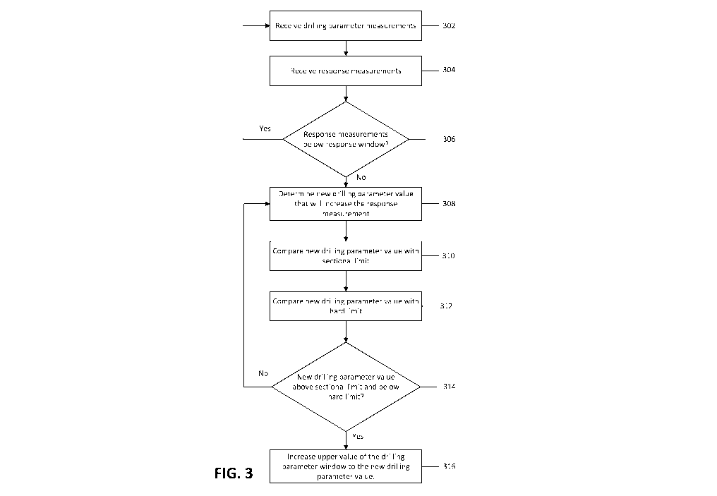
[0078] Figure 3 illustrates one embodiment of a method for dynamically
adjusting drilling
parameters during a drilling operation. In one embodiment, the method involves
receiving 302
drilling parameter measurements in real time during a drilling operation. As
used herein, a drilling
16
CA 03205426 2023-06-14
WO 2022/133484 PCT/US2021/072988
parameter refers to a parameter that can be changed directly or indirectly and
that creates a
measurable response. The drilling parameters may be for surface equipment, a
downhole tool, or
both. The drilling parameters being measured may be rate of penetration,
surface drillstring
rotation speed, block speed, pump stroke rate, others, or a combination of
different drilling
parameters being measured.
[0079] The method may also involve receiving 304 response measurements during
the drilling
operation. As discussed above, responses are changes in values that result
from changes to the
drilling parameters. As noted above, an example includes changes in
drillstring torque in response
to changes in RPM. Another example is a change to differential pressure across
a motor in response
to changes in rate of penetration (ROP). The response measurement may be, for
example,
drillstring torque, hookload, weight on bit, differential pressure, or a
combination thereof.
[0080] The method may involve determining 306 whether the response measurement
is within
a response window that defines a desired lower limit and a desired upper limit
for the response
measurement. While the response measurement is within the response window, the
method may
involve continuously monitoring the drilling parameters and the responses. In
response to
determining that the response measurement is below the desired lower limit,
the method may
involve taking corrective action to return the response measurement to the
window. In certain
embodiments, the method may trigger the corrective action even when the
response measurement
is still within the response window if it determines that the response
measurement is trending
downwards towards the desired lower limit of the response window.
[0081] In one embodiment, the method involves determining a rate of change of
the response
measurement and estimating the amount of time it will take for a change in a
drilling parameter to
impact the response measurement. In such an embodiment, the method may trigger
changes to the
drilling parameter while there is sufficient time to impact the response
measurement and keep it
within the response window.
[0082] In one embodiment, the approach involves averaging response
measurements over a
period of time to smooth the response measurements and remove noise from the
response
measurements. Other approaches to reducing or removing noise from the response
measurements
can also be used. In this document, decisions made using measurements may
refer to decisions
made using the raw measurements themselves or smoothed, processed, or cleaned
measurement
data.
17
CA 03205426 2023-06-14
WO 2022/133484 PCT/US2021/072988
[0083] The method may involve, in response to determining that the response
measurement is
below the desired lower limit of the response window or trending downwards,
determining 308
new drilling parameter values that will increase the response measurement. The
method may also
involve comparing 310 the new drilling parameter values to sectional limits
and comparing 312
the new drilling parameter value with hard limits.
[0084] If the new drilling parameter value is below both the sectional limit
and the hard limit,
the method may involve taking no additional action. In one embodiment, it may
involve
considering other drilling parameter values. In another embodiment, it may
involve continuing to
monitor the drilling parameters and response measurements. In one embodiment,
it may involve
changing the drilling parameter to the new value or providing a driller with
an instruction to change
the drilling parameter without making adjustments to the limits of the
drilling parameter. In such
an embodiment, the drilling operation may continue with the new drilling
parameter while still
acting within the sectional limits and the hard limits.
[0085] In another instance, the drilling parameter value may be above the hard
limit. In such an
embodiment, the method may involve searching for a different drilling
parameter that may impact
the response. The method may involve increasing the upper value of the
drilling parameter window
to the new drilling parameter value, but only to the level of the hard limit.
For example, a system
may determine that a new RPM value 'a' will help mitigate a stick slip
condition, where the
sectional limit for RPM is 'b' and the hard limit is 'c' and a > c and a > b.
In such a case, the
system may increase the limit for the RPM above the sectional limit 'b' to the
hard limit c,' not
the larger RPM value 'a.'
[0086] The drilling parameter value may be above the sectional limit and below
the hard limit.
The method may involve, in such a case, increasing 316 the upper value of the
drilling parameter
window for the drilling parameter to the new drilling parameter value. In some
cases, the method
may involve automatically increasing the drilling parameter to the new
drilling parameter value
that will increase the response measurement. For example, an autonomous
drilling system may
increase the drilling parameter value. In another embodiment, the method
involves increasing the
upper value of the drilling parameter window and providing a notification to a
driller of the change
in the upper limit. The method may also provide a recommendation to the
driller to use the new
drilling parameter value.
18
CA 03205426 2023-06-14
WO 2022/133484 PCT/US2021/072988
[0087] The method may also provide an explanation to the driller for the
recommendation. For
example, a system may provide a message to the driller indicating that the
response measurement
is outside the response window or trending downwards, and that using the new
drilling parameter
value may mitigate the downward trend or return the response measurement to
the window.
[0088] The method may also involve monitoring the response measurement after
increasing the
drilling parameter to the new drilling parameter value. The method may involve
determining
whether the response measurement is stabilizing within the response window
and, in response,
resetting the upper value of the drilling parameter window to the sectional
limit for the drilling
parameter. In such an embodiment, the sectional limit may still be considered
the preferred limit
for the drilling parameters and the method may default back to the sectional
limits once the
response measurement returns to an acceptable range. Once the response
measurement returns to
the response window, the method of figure 3 may begin again with a system
monitoring the drilling
parameter measurements and the response measurements as described above.
[0089] In certain embodiments, the method may involve gradually increasing the
upper limit of
the drilling parameter window to the new drilling parameter value. For
example, it may be
desirable to smoothly ramp up a drilling parameter over a period of time. In
such an embodiment,
the method may generate transition values for the drilling parameter window
that gradually
transition the upper limit of the drilling parameter window to the new
drilling parameter value.
Similarly, the method may generate transition values for the drilling
parameter window to
gradually transition the drilling parameter window back to the sectional limit
for the drilling
parameter when the response measurement recovers and stabilizes within the
response window.
[0090] While the example above describes the method in connection with one
drilling parameter,
it will be appreciated that the approach may be expanded to multiple drilling
parameters. In such
an embodiment, the method may involve determining new drilling parameter
values for multiple
drilling parameters that, in combination, will increase the response
measurement. The method may
involve comparing the drilling parameter values for one or more of this group
of drilling
parameters to their respective sectional limits and hard limits. As above, for
drilling parameter
values that are above the sectional limits and below the hard limits, the
approach may involve
increasing the upper values for the drilling parameter windows with their
respective drilling
parameter values.
19
CA 03205426 2023-06-14
WO 2022/133484 PCT/US2021/072988
[0091] In such an embodiment, the system may give preference to those drilling
parameter
values that are above the sectional limits and below the hard limits. For
example, if a particular
drilling parameter value is above both the sectional limit and the hard limit,
the approach may look
for a different parameter to adjust. In another embodiment, the method
involves making the
adjustments to all drilling parameter values that are associated with the
response measurement
while respecting the hard limits as described above.
[0092] In one embodiment, the method involves minimizing the deviation from
the sectional
limits. For example, multiple drilling parameters may have an impact on a
response measurement.
In such an embodiment, new drilling parameter values may be determined for
each of the drilling
parameters that impact the response measurement. The system may determine the
new drilling
parameter values that will return the response measurement to the response
window while
minimizing the deviation from the sectional limit. For example, the method may
involve applying
a cost function to find the values of the drilling parameters that minimize
the different between the
new drilling parameter values and the sectional limits. Such an approach may
facilitate the
selection of new drilling parameter values that will return the response
measurement to the
response window while maintaining, to the extent possible, the benefits of
adhering to or staying
close to the sectional limits.
[0093] As noted above, the method may also involve displaying via a computing
system the
drilling parameter window created using the new drilling parameter values. The
computing system
may be part of a control system and allow the driller to adjust the drilling
parameters within the
drilling parameter window. In another embodiment, a control system in
autonomous mode adjusts
the drilling rig operation to execute the drilling operation within the
drilling parameter window
created using the new drilling parameter values.
[0094] As discussed above, the method described in Figure 3 can be
successfully applied to a
range of scenarios where particular drilling parameters can be used to adjust
response
measurements. Figure 4 illustrates one particular implementation of this
approach to a particular
response measurement. Figure 4 is provided by way of illustration, and does
not limit the
applicability of the broader approach to different problems with different
drilling parameters and
different drilling responses.
[0095] In the particular example of Figure 4, the method involves measuring
402, in real time,
the rate of penetration (ROP) during a directional drilling operation. The
method may also involve
CA 03205426 2023-06-14
WO 2022/133484 PCT/US2021/072988
measuring 404, in real time, the differential pressure across a motor that is
part of a bottom hole
assembly (BHA) during the directional drilling operation. The method may
involve determining
406 whether the differential pressure is within a predefined differential
pressure window that
specifies the lower limit for the differential pressure and the upper limit
for the differential
pressure. In response to determining that the differential pressure is below
the lower limit of the
predefined differential pressure window or trending downwards towards the
predefined
differential pressure window, the method may involve determining 408 a new ROP
value that will
increase the differential pressure. The method may also involve comparing 410
that new ROP
value with the sectional limit for ROP and comparing 412 the new ROP value
with the hard limit
for ROP.
[0096] The method may involve determining 414 whether the new ROP is above the
sectional
limit and below the hard limit. In response to the new ROP value being above
the sectional limit
and below the hard limit, the method may involve increasing 416 the upper
value of the ROP
window to the new ROP value.
[0097] As discussed above, if the new ROP value is above the sectional limit
and above the hard
limit, the method may involve setting the new ROP value to the hard limit and
increasing the upper
value of the ROP window to the hard limit. In one embodiment, if the new ROP
value is equal to
or below both the sectional limit and the hard limit, the method may involve
increasing the ROP
without changing the upper value of the ROP window.
[0098] In certain embodiments, the method involves automatically increasing
the ROP to the
new ROP value that will increase the differential pressure. The method may
also involve providing
a notification to a driller of the increase in ROP along with an explanation
for the increase. In
another embodiment, the method may involve providing a driller with an
instruction to increase
the ROP and providing the driller with the updated ROP window.
[0099] While the above example describes updating the upper bound of the ROP
window, a
similar process may be used to update the lower bound of the ROP window. For
example, the
method may involve determining a minimum ROP that is different from the
sectional limit and
provide an updated lower bound for the ROP window as well. In some
embodiments, the ROP
window (or the drilling parameter more generally) may include only an upper
bound. As used
herein, an ROP window (or a drilling parameter window) includes such cases
where only one of
an upper bound and lower bound is provided.
21
CA 03205426 2023-06-14
WO 2022/133484 PCT/US2021/072988
[00100] In certain embodiments, after the ROP is increased and the ROP window
is updated with
the new limits, the method involves monitoring the differential pressure after
increasing the ROP
to the new ROP value and determining whether the differential pressure is
stabilizing within the
predefined differential pressure window. In response to the differential
pressure stabilizing, the
method may involve resetting the upper value of the ROP window to the
sectional limit for the
ROP.
[00101] As discussed in connection with Figure 3 more generally, other
parameters may be
associated with differential pressure. In certain embodiments, the method
involves identifying new
values for drilling parameters in addition to ROP that will increase the
differential pressure and,
for these additional drilling parameters, comparing the new values with the
sectional limits and
the hard limits for them. As described above in connection with ROP, the upper
values of the
windows for these additional drilling parameters may also be increased to
respective new values
for the additional drilling parameters.
[00102] Figure 5A illustrates one embodiment of a differential pressure and
ROP relationship as
described above. Figures 5A and 5B illustrate example measurements displayed
on a time and
depth chart with time values (such as 18:37:30) and depth values (such as
12237) along they axis.
The x axis illustrates sets of values shown along the time-depth values. From
left to right, Figure
5A illustrates differential pressure measurements 502 and ROP measurements
504.
[00103] The far right illustrates ROP measurements 504. In the illustrated
embodiment, this
includes the ROP limit 522 shown as a solid black line. As illustrated, the
ROP limit 522 may be
a maximum value only. In other embodiments, a lower ROP limit 522 may also be
specified
defining an ROP window. As shown in Figures 5A and 5B, the ROP limit 522 may
vary.
[00104] The illustrated embodiment shows the original ROP 520 as the heavy
dotted line. The
illustrated embodiment shows the driller following the ROP limit 522 closely.
As illustrated,
proceeding with the drilling according to the ROP parameter specified by the
original ROP 520
results in the original differential pressure 510 shown in the differential
pressure measurements
502. In the illustrated embodiment, while using the original ROP 520 parameter
results in close
adherence to the ROP limit 522, the original differential pressure 510 is
frequently outside the
differential pressure window specified by the differential pressure limits
512.
[00105] Figure 5B illustrates the same example, but with the addition of
dynamic adjustment of
the ROP drilling parameter as described herein. The trigger 505 represents one
approach to
22
CA 03205426 2023-06-14
WO 2022/133484 PCT/US2021/072988
determining whether the response measurement is within a response window or
trending
downwards. As shown in Figure 5B, the trigger 505 may a value between, for
example, -0.1 and
1.1. In the illustrated embodiment, the trigger 505 causes the adjustments to
the ROP value when
it is high and causes the system to revert to the sectional limits when it is
low.
[00106] Figure 5B illustrates the response of the trigger 505 to measurements
of the new
differential pressure 514. Differential pressure limits 512 represent the
response window for the
differential pressure in this example. In Figure 5B, the differential pressure
limits 512 represent
the lower and upper boundaries for the differential pressure within a
particular section. While the
illustrated embodiment shows the differential pressure limits 152 as static
values, the differential
pressure limits 512 may vary in different wells, or different sections of the
same well.
[00107] As seen in Figure 5B, When the new differential pressure 514 is
steadily below the
differential pressure limits 512, or decreasing towards the lower limit of the
differential pressure
limits 512, the trigger 505 has a high value triggering adjustments to the ROP
value and ROP limit
522. When the new differential pressure 514 measurements are stable or
trending upwards, the
system may deactivate the trigger 505 and the ROP limit 522 and recommended
ROP parameter
revert to the sectional limit. The sensitivity of the trigger 505 to changes
may be tuned to reduce
the likelihood of the trigger 505 being activated in response to noise or
fluctuations at or near the
differential pressure limits 512.
[00108] The ROP measurements 504 show the new ROP 524 values and the original
ROP
limit 522. In comparison to the embodiment shown in Figure 5A, the new ROP 524
values do not
adhere as closely to the ROP limit 522. However, Figure 5B illustrates how the
dynamic
adjustment of the ROP limit 522 results in a new differential pressure 514
value that is within the
window defined by the differential pressure limits 512 more than the case
shown in Figure 5A.
[00109] In the illustrated embodiment, the driller or system frequently
changes the new ROP 524
in the section to control the new differential pressure 514. When the trigger
505 is active (high),
the system may relax the ROP limit 522. In one embodiment, the system relaxes
the ROP limit
522 by fifty feet per hour.
[00110] The new ROP limit is not shown in Figure 5B for clarity; however, in
the illustrated
embodiment, the new ROP limit is dynamically increasing to a level that is
above the sectional
limit for the ROP (represented by the ROP limit 522) but below the hard limits
for the ROP, above
which operating the ROP would result in risks to safety, equipment, or the
well. This approach
23
CA 03205426 2023-06-14
WO 2022/133484 PCT/US2021/072988
strikes a balance between protecting safety and equipment (by adhering to hard
limits), using the
expertise of the team (by using sectional limits by default), while still
maintaining the flexibility
to respond appropriately to events (such as the differential pressure 514
falling outside of the
differential pressure limits 514) to provide a result that more consistently
provides response
measurements that are within specified windows.
[00111] The approach described herein may be implemented as a set of
instructions to be saved
in memory and executed by a processor. The computer system may be part of a
drilling system. In
certain embodiments, the computer system may be part of a drilling system as
illustrated in Figure
2. The drilling system may include a rig control system that communicates with
the rig equipment.
In one embodiment, the computer system may be part of the rig control system.
In another
embodiment, the computer system may be separate from the rig control system
and communicate
with the rig control system using a software interface.
[00112] As discussed above, the computer system may receive, in real time,
drilling parameter
measurements and response measurements during the drilling operation. The
computer system
may determine whether the response measurements are within the response window
that defines
the desired lower limit and the desired upper limit for the response
measurements. In response to
determining that the response measurement is below the desired lower limit, or
trending
downwards towards the desired lower limit, the computer system may determine a
new drilling
parameter value that will increase the response measurement.
[00113] The computer system may compare the new drilling parameter value with
sectional limits
and hard limits for the drilling parameter value. If the drilling parameter
value is above the
sectional limit and below the hard limit, the computer system may increase the
upper value of the
drilling parameter window to the new drilling parameter. The computer system
may also increase
the drilling parameter itself (or instruct a driller to do so) to a value that
is equal to or below the
updated upper value. This approach may be used to dynamically adjust both the
drilling parameter
values that define the window of acceptable values for the drilling parameter
and to also update
the drilling parameter itself.
[00114] In some embodiments, the methods of the present disclosure may be
executed by a
computing system. Figure 6 illustrates an example of such a computing system
600, in accordance
with some embodiments. The computing system 600 may include a computer or
computer system
601A, which may be an individual computer system 601A or an arrangement of
distributed
24
CA 03205426 2023-06-14
WO 2022/133484 PCT/US2021/072988
computer systems. The computer system 601A includes one or more analysis
modules 602 that
are configured to perform various tasks according to some embodiments, such as
one or more
methods disclosed herein. To perform these various tasks, the analysis module
602 executes
independently, or in coordination with, one or more processors 604, which is
(or are) connected to
one or more storage media 606. The processor(s) 604 is (or are) also connected
to a network
interface 607 to allow the computer system 601A to communicate over a data
network 609 with
one or more additional computer systems and/or computing systems, such as
601B, 601C, and/or
601D (note that computer systems 601B, 601C and/or 601D may or may not share
the same
architecture as computer system 601A, and may be located in different physical
locations, e.g.,
computer systems 601A and 601B may be located in a processing facility, while
in communication
with one or more computer systems such as 601C and/or 601D that are located in
one or more data
centers, and/or located in varying countries on different continents).
[00115] A processor may include a microprocessor, microcontroller, processor
module or
subsystem, programmable integrated circuit, programmable gate array, or
another control or
computing device.
[00116] The storage media 606 may be implemented as one or more computer-
readable or
machine-readable storage media. Note that while in the example embodiment of
Figure 6 storage
media 606 is depicted as within computer system 601A, in some embodiments,
storage media 606
may be distributed within and/or across multiple internal and/or external
enclosures of computing
system 601A and/or additional computing systems. Storage media 606 may include
one or more
different forms of memory including semiconductor memory devices such as
dynamic or static
random access memories (DRAMs or SRAMs), erasable and programmable read-only
memories
(EPROMs), electrically erasable and programmable read-only memories (EEPROMs)
and flash
memories, magnetic disks such as fixed, floppy and removable disks, other
magnetic media
including tape, optical media such as compact disks (CDs) or digital video
disks (DVDs),
BLURAY disks, or other types of optical storage, or other types of storage
devices. Note that the
instructions discussed above may be provided on one computer-readable or
machine-readable
storage medium, or may be provided on multiple computer-readable or machine-
readable storage
media distributed in a large system having possibly plural nodes. Such
computer-readable or
machine-readable storage medium or media is (are) considered to be part of an
article (or article
of manufacture). An article or article of manufacture may refer to any
manufactured single
CA 03205426 2023-06-14
WO 2022/133484 PCT/US2021/072988
component or multiple components. The storage medium or media may be located
either in the
machine running the machine-readable instructions, or located at a remote site
from which
machine-readable instructions may be downloaded over a network for execution.
[00117] In some embodiments, computing system 600 contains one or more
drilling control
module(s) 608. In the example of computing system 600, computer system 601A
includes the
drilling control module 608. In some embodiments, a single drilling control
module may be used
to perform some aspects of one or more embodiments of the methods disclosed
herein. In other
embodiments, a plurality of drilling control modules may be used to perform
some aspects of
methods herein.
[00118] It should be appreciated that computing system 600 is merely one
example of a
computing system, and that computing system 600 may have more or fewer
components than
shown, may combine additional components not depicted in the example
embodiment of Figure
6, and/or computing system 600 may have a different configuration or
arrangement of the
components depicted in Figure 6. The various components shown in Figure 6 may
be implemented
in hardware, software, or a combination of both hardware and software,
including one or more
signal processing and/or application specific integrated circuits.
[00119] Further, the steps in the processing methods described herein may be
implemented by
running one or more functional modules in information processing apparatus
such as general
purpose processors or application specific chips, such as ASICs, FPGAs, PLDs,
or other
appropriate devices. These modules, combinations of these modules, and/or
their combination with
general hardware are included within the scope of the present disclosure.
[00120] Computational interpretations, models, and/or other interpretation
aids may be refined in
an iterative fashion; this concept is applicable to the methods discussed
herein. This may include
use of feedback loops executed on an algorithmic basis, such as at a computing
device (e.g.,
computing system 600, Figure 6), and/or through manual control by a user who
may make
determinations regarding whether a given step, action, template, model, or set
of curves has
become sufficiently accurate for the evaluation of the subsurface three-
dimensional geologic
formation under consideration.
Conclusion
[00121] The embodiments disclosed in this disclosure are to help explain the
concepts described
herein. This description is not exhaustive and does not limit the claims to
the precise embodiments
26
CA 03205426 2023-06-14
WO 2022/133484 PCT/US2021/072988
disclosed. Modifications and variations from the exact embodiments in this
disclosure may still
be within the scope of the claims.
[00122] Likewise, the steps described need not be performed in the same
sequence discussed or
with the same degree of separation. Various steps may be omitted, repeated,
combined, or divided,
as appropriate. Accordingly, the present disclosure is not limited to the
above-described
embodiments, but instead is defined by the appended claims in light of their
full scope of
equivalents. In the above description and in the below claims, unless
specified otherwise, the term
"execute" and its variants are to be interpreted as pertaining to any
operation of program code or
instructions on a device, whether compiled, interpreted, or run using other
techniques.
[00123] The claims that follow do not invoke section 112(f) unless the phrase
"means for" is
expressly used together with an associated function.
27