Note: Descriptions are shown in the official language in which they were submitted.
- 1 -
HEART VALVE DOCKING DEVICES AND IMPLANTING METHODS
BACKGROUND
Field
[0001] The present disclosure generally concerns prosthetic heart valves
and
associated devices and related methods for implanting such devices. More
specifically,
the disclosure relates to the repair and replacement of heart valves that have
malformations and/or dysfunctions, where an additional dock or anchor is
utilized
together with the prosthetic heart valve at the implant site, and methods of
implanting
such anchors and/or prosthetic heart valves.
Description of Related Art
[0002] The native mitral valve controls the flow of blood from the left
atrium to the
left ventricle of the human heart. The mitral valve has a very different
anatomy than other
native heart valves. The mitral valve includes an annulus made up of native
valve tissue
surrounding the mitral valve orifice, and a pair of cusps or leaflets
extending downward
from the annulus into the left ventricle. The mitral valve annulus can form a
"D" shaped,
oval shaped, or otherwise non-circular cross-sectional shape having major and
minor
axes. An anterior leaflet can be larger than a posterior leaflet of the valve,
forming a
generally "C" shaped boundary between the abutting free edges of the leaflets
when they
are closed together.
[0003] When operating properly, the anterior leaflet and the posterior
leaflet of the
mitral valve function together as a one-way valve to allow blood to flow only
from the left
atrium to the left ventricle. After the left atrium receives oxygenated blood
from the
pulmonary veins, the muscles of the left atrium contract and the left
ventricle dilates (also
referred to as "ventricular diastole" or "diastole"), and the oxygenated blood
that is
collected in the left atrium flows into the left ventricle. Then, the muscles
of the left
atrium relax and the muscles of the left ventricle contract (also referred to
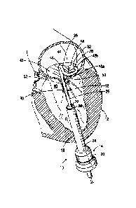
as "ventricular
systole" or "systole"), to move the oxygenated blood out of the left ventricle
and through
Date Recue/Date Received 2023-07-07
- 2 -
the aortic valve to the rest of the body. The increased blood pressure in the
left ventricle
during ventricular systole urges the two leaflets of the mitral valve
together, thereby
closing the one-way mitral valve so that blood cannot flow back into the left
atrium. To
prevent the two leaflets from prolapsing under the pressure and folding back
through the
mitral annulus toward the left atrium during ventricular systole, a plurality
of fibrous
cords called chordae tendineae tether the leaflets to papillary muscles in the
left ventricle.
[0004] One common form of valvular heart disease is mitral valve leak, also
known as
mitral regurgitation. Mitral regurgitation occurs when the native mitral valve
fails to close
properly and blood flows back into the left atrium from the left ventricle
during the
systolic phase of heart contraction. Mitral regurgitation has different
causes, such as
leaflet prolapse, dysfunctional papillary muscles, and/or stretching of the
mitral valve
annulus resulting from dilation of the left ventricle. In addition to mitral
regurgitation,
mitral narrowing or stenosis is another example of valvular heart disease.
[0005] Like the mitral valve, the aortic valve is susceptible to
complications such as
aortic valve stenosis. One method for treating such valvular heart disease
includes the use
of a prosthetic valve implanted within the native heart valve. These
prosthetic valves can
be implanted using a variety of techniques, including various transcatheter
techniques.
One transcatheter technique that is commonly used for accessing a native valve
is the
transseptal technique, where a catheter accesses the left side of the heart
via a femoral
vein, the inferior vena cava, the right atrium, and then a puncture hole in
the interatrial
septum. A prosthetic valve can then be mounted in a crimped state on the end
portion of
a second, flexible and/or steerable catheter, advanced to the implantation
site, and then
expanded to its functional size, for example, by inflating a balloon on which
the valve is
mounted. Alternatively, a self-expanding prosthetic valve can be retained in a
radially
compressed state within a sheath of a delivery catheter, and the prosthetic
valve can be
deployed from the sheath, which allows the prosthetic valve to expand to its
functional
state.
[0006] Another common transcatheter technique for implanting a prosthetic
valve is a
transventricular approach, where a small incision is made in the chest wall
and the
Date Recue/Date Received 2023-07-07
- 3 -
ventricular wall of a patient, and then a catheter or introducer sheath is
inserted into the
left ventricle. A delivery catheter containing or holding the prosthetic valve
can then be
advanced through the introducer sheath to the implantation site.
[0007] Such prosthetic valves are generally better developed for
implantation or use at
the aortic valve. However, similar catheter-based prosthetic valves can be
more difficult
to apply or implant at the native mitral valve due to the structural
differences between the
aortic and mitral valves. For example, the mitral valve has a more complex
subvalvular
apparatus, which includes the chordae tendineae. Additionally, the native
mitral valve is
less circular in shape and typically does not provide sufficient structure for
anchoring and
resisting migration of a prosthetic valve.
SUMMARY
[0008] Since many valves have already been developed for the aortic
position, it
would be desirable to try to take advantage of these existing valve
technologies and to
utilize the same or similar valves for tricuspid, pulmonic and mitral valve
replacements.
One way of utilizing these preexisting prosthetic valves is to use the
prosthetic valves
together with an anchor or other docking station that will form a more
appropriately
shaped implant site at the native valve annulus, so that the prosthetic valve
can be
implanted more securely, while reducing or eliminating leakage around the
valve after
implantation. For example, a mitral anchor or docking station can form a more
circular
bore at the annulus to more closely match the circular profiles of existing
aortic valve
implants. In this manner, an existing valve implant developed for the aortic
position,
perhaps with some modification, could then be implanted at the mitral position
together
with such an anchor. In addition, such anchors could also potentially be used
at the
heart's other native valves to more securely anchor prosthetic valves at those
sites as well.
[0009] Described herein are embodiments of prosthetic devices that are
primarily
intended to be implanted at one of the native mitral, aortic, tricuspid, or
pulmonary valve
regions of a human heart, as well as apparatuses and methods for implanting
the same.
The prosthetic devices can be used to repair the native valve annulus, as well
as to
Date Recue/Date Received 2023-07-07
- 4 -
position and secure a prosthetic heart valve in the native valve region. The
disclosed
devices can include a helical anchor having a plurality of turns or coils,
where the helical
anchor can assume an axially collapsed position where portions of at least two
of the coils
align or overlap in a radial direction.
[0010] In one embodiment, a helical device for implanting at a native heart
valve of a
heart of a patient includes an upper coil and a lower coil, and a central axis
extending
through the upper coil and the lower coil. The device is configured to assume
an axially
expanded state where the entire upper coil is positioned on a first side of
the lower coil
relative to the central axis, and is also configured to assume an axially
compressed state
where at least a portion of the upper coil is positioned on a second side of
at least a portion
of the lower coil opposite to the first side relative to the central axis. The
device can
include a first set of one or more coils comprising the upper coil having a
first inner
diameter, and a second set of one or more coils comprising the lower coil
having an inner
diameter different from the first inner diameter.
[0011] In certain embodiments, the device can include a first set of coils
having at
least two coils and a second set of coils having at least two coils. At least
one of the coils
of the first set of coils is positioned relative to the central axis between
two coils of the
second set of coils when the device is in the compressed state. The first set
of coils can be
configured to be positioned on a ventricular side of a native valve, and the
second set of
coils can be configured to be positioned on an atrial side of the native
valve. Preferably,
the upper and lower coils are made from a shape-memory material, such a
Nitinol.
[0012] In another embodiment, a method of implanting a helical device,
including an
upper coil and a lower coil, at a native valve of a heart of a patient,
involves positioning
the lower coil on a ventricular side of the native valve, positioning the
upper coil on an
atrial side of the native valve, such that the entire upper coil is positioned
on a first side of
the lower coil relative to a central axis of the device, and adjusting the
device to a position
where at least a portion of the upper coil is positioned on a second side of
at least a
portion of the lower coil opposite to the first side relative to the central
axis.
Date Recue/Date Received 2023-07-07
- 5 -
[0013] The method can include implanting a prosthetic heart valve within
the device.
The prosthetic heart valve is positioned in the device when the prosthetic
heart valve is in
a radially compressed state, and the prosthetic heart valve is radially
expanded such that a
radial pressure is applied between the prosthetic heart valve and the device
to anchor the
prosthetic heart valve within the device
[0014] In another embodiment, a system for securing a prosthetic heart
valve at a
native heart valve of a heart of a patient includes a helical docking device
including an
upper coil and a lower coil, where a central axis extends through the upper
coil and the
lower coil, and a prosthetic heart valve configured to be held in the docking
device. The
docking device is configured to assume an axially expanded state where the
entire upper
coil is positioned on a first side of the lower coil relative to the central
axis, and is also
configured to assume an axially compressed state where at least a portion of
the upper coil
is positioned on a second side of at least a portion of the lower coil
opposite to the first
side relative to the central axis. The system can include a delivery catheter
configured to
deploy the docking device at the native heart valve.
BRIEF DESCRIPTION OF THE DRAWINGS
[0015] The foregoing and other objects, features, and advantages of the
invention will
become more apparent from the following detailed description using the
accompanying
figures. In the drawings:
[0016] FIG. 1A shows a schematic cross-sectional view of a human heart;
[0017] FIG. 1B shows a schematic top view of the mitral valve annulus of a
heart;
[0018] FIGS. 2A-2C respectively show a perspective view, a side view, and a
top
view of a helical device according to a first embodiment of the invention;
[0019] FIGS. 3A and 3B respectively show a perspective view and a cross-
sectional
view of a compressed state of the helical device of FIGS. 2A-2C;
[0020] FIGS. 4A-4M show one embodiment of a delivery apparatus and method
for
implanting a helical docking device and a prosthetic valve at the native
mitral valve of a
heart, using a transventricular technique;
Date Recue/Date Received 2023-07-07
- 6 -
[0021] FIGS. 5A-5E show another embodiment of a delivery apparatus and
method
for implanting a helical device at the native mitral valve of a heart, using a
transseptal
technique;
[0022] FIG. 6A shows a perspective view of a helical docking device
according to a
second embodiment of the invention;
[0023] FIGS. 6B-6D show various cross-sectional views of the helical
docking device
of FIG. 6A implanted at the native mitral valve of a heart;
[0024] FIG. 7A shows a perspective view of an expanded state of a helical
docking
device according to a third embodiment of the invention;
[0025] FIGS. 7B and 7C show cross-sectional views of the helical docking
device of
FIG. 7A at the native mitral valve of a heart;
[0026] FIG. 8A shows a perspective view of an expanded state of a helical
docking
device according to a fourth embodiment of the invention;
[0027] FIGS. 8B and 8C show cross-sectional views of the helical docking
device of
FIG. 8A at the native mitral valve of a heart; and
[0028] FIGS. 9A-9C show perspective views of a portion of a delivery
catheter for a
helical docking device, according to one embodiment.
DETAILED DESCRIPTION
[0029] Described herein are embodiments of prosthetic devices that are
primarily
intended to be implanted at one of the native mitral, aortic, tricuspid, or
pulmonary valve
regions of a human heart, as well as apparatuses and methods for implanting
the same.
The prosthetic devices can be used to repair a native valve and to position
and secure a
prosthetic heart valve in the native valve region. These prosthetic devices
can improve
the functionality of the prosthetic heart valves, in order to better repair
replace or replicate
the functionality of a defective native heart valve. The present disclosure is
directed
toward all features and aspects of the various disclosed embodiments, both
alone and in
various combinations and sub-combinations with one another.
Date Recue/Date Received 2023-07-07
- 7 -
[0030] In particular embodiments, a prosthetic assembly includes an
anchoring or
docking device configured to be implanted at or adjacent the native valve and
configured
to receive and retain a prosthetic valve. The docking device can be delivered
and
implanted in a minimally invasive manner via the left ventricle and/or the
left atrium,
after which a separate prosthetic valve can be delivered and implanted within
the docking
device in a minimally invasive manner.
[0031] In particular embodiments, a docking device includes a helical
anchor having a
plurality of turns or coils with at least one of the coils having a negative
pitch relative to
an adjacent coil when the helical anchor is in at least one state, for
example, its
undeformed or non-tensioned state. As used herein, the "pitch" of a helical
anchor is the
distance from the center of one coil to the center of an adjacent coil. In a
typical helix, the
coils extend in a same axial direction, such that each coil can be said to
have a positive
pitch with respect to a preceding coil in this axial direction. However, if
one of the turns
or coils doubles over on an outside or an inside of its preceding coil, then
it could be said
that that particular coil extends in a direction opposite to the positive
axial direction,
making the pitch of that coil "negative" relative to its preceding coil. Thus,
a coil with a
"negative pitch" extends along the longitudinal axis of the helical anchor in
a direction
opposite to the direction of extension of the other coils in the helical
anchor. In some
embodiments, a helical anchor can be pre-formed with at least one coil having
a negative
pitch relative to other coils in the anchor when the anchor is in its
undeformed or non-
tensioned state. In these embodiments, when the helical anchor is held in a
tensioned
stated, the pitch as measured from a first coil to a second coil extends in a
first direction
and defines a positive pitch, and when the helical anchor is released from the
tensioned
state, the second coil can move axially back towards and past the first coil,
such that the
second coil extends in the opposite direction and defines a negative pitch. As
such, the
first coil can be disposed at least partially within (i.e., radially inward
from) the second
coil, or vice versa, in such a non-tensioned state. The anchor can be adjusted
to its final
position by self-aligning or by being guided or installed by the delivery
system.
Date Recue/Date Received 2023-07-07
- 8 -
[0032] FIGS. 2A-3B show a helical docking device 34 according to a first
embodiment of the invention. The docking device 34 includes first and second
lower or
ventricular coils 54a, 54b configured to be positioned on the ventricular side
of the native
valve, and first and second upper or atrial coils 56a, 56b configured to be
positioned on the
atrial side of the native valve. Although the illustrated docking device 34
has two
ventricular coils and two atrial coils, other embodiments of the docking
device can have a
greater or fewer number of ventricular coils and/or atrial coils.
[0033] In the embodiment of Figs. 2A-3B, the atrial coils 56a, 56b have an
inner
diameter that is different than the inner diameter of the ventricular coils
54a, 54b, to
facilitate nesting or positioning of the atrial coils within the ventricular
coils when the
docking device 34 is in a compressed state. As shown in FIGS. 2B-2C, the
atrial coils
56a, 56b have an inner diameter 72 that is less than the inner diameter 74 of
the
ventricular coils 54a, 54b. Larger ventricular coils can, for example, make it
easier to
loop the ventricular coils 54a, 54b around the leaflets of the native mitral
valve and/or
the chordae tendineae. Larger ventricular coils can also, for example, allow
the docking
device and a docked prosthetic heart valve to be placed higher in the native
valve (i.e.,
towards the atrium), as further described below.
[0034] The atrial coils 56a, 56b can have an inner diameter 72 of about 22
mm to
about 30mm, with about 25 mm being a specific example. The ventricular coils
can have
an inner diameter 74 of about 24 mm to about 32 mm, with about 27 mm being a
specific
example. The coil wire can have a diameter of about 0.3 mm to about 1.2 mm,
with about
1 mm being a specific example. When the docking device 34 is in the axially
compressed
state (e.g., as seen in FIGS. 3A-3B), the innermost diameter of the docking
device can be
about 25 mm, and the outermost diameter of the docking device can be about 29
mm.
The prosthetic valve 36 can be selected to have a nominal outer diameter that
is slightly
larger than the innermost diameter of the docking device to create sufficient
anchoring
force between the prosthetic valve and the docking device in the radial
direction to hold
the prosthetic valve in place. For example, a docking device having the
dimensions
provided above can be used with a 26 mm prosthetic valve.
Date Recue/Date Received 2023-07-07
- 9 -
[0035] In alternative embodiments, the inner diameter of the atrial coils
can be greater
than the inner diameter of the ventricular coils (e.g., as seen in Figs. 6A-
6D, described in
greater detail below).
[0036] In particular embodiments, the inner diameter of each ventricular
coil can be
substantially the same, and/or the inner diameter of each atrial coil can be
substantially
the same. As such, when the docking device 34 moves from the axially expanded
state to
the axially compressed state, as further described below, the ventricular
coils 54a, 54b
axially overlap with the atrial coils 56a, 56b in a manner similar to a
cylinder within a
cylinder.
[0037] In other embodiments, the inner diameter of each of the atrial and
ventricular
coils can vary. For example, an atrial coil can have an inner diameter that is
greater than
or less than the inner diameter of another atrial coil, and a ventricular coil
can have an
inner diameter that is greater than or less than the inner diameter of another
ventricular
coil. In addition, one or more atrial coils can have an inner diameter that is
the same as
one or more ventricular coils.
[0038] In one embodiment, docking device 34 is axially expandable when
tension is
applied to one or both ends of the docking device 34, and is axially
compressible when
tension is released from the docking device 34. In this manner, the docking
device 34 can
be said to be made up of or act similarly to a tension spring. FIGS. 2A-2C
show the
docking device in an axially expanded state such that all the coils have a
positive pitch
with respect to adjacent coils. That is, the second ventricular coil 54b is
located upstream
of the first ventricular coil 54a in the axial direction (i.e., upwards as
illustrated), the first
atrial coil 56a is located upstream of the second ventricular coil 54b, and
the second atrial
coil 56b is located upstream of the first atrial coil 56a. Therefore, in this
embodiment, a
positive pitch direction can be defined as being oriented in the upstream or
upwards
direction.
[0039] Meanwhile, FIGS. 3A-3B show the docking device 34 in an axially
compressed state, for example, after tension is released from the docking
device 34. In
this state, the first atrial coil 56a moves, or is activated by a delivery
system, axially past
Date Recue/Date Received 2023-07-07
- 10 -
the center of the second ventricular coil 54b in the downstream direction
(i.e., downwards
as illustrated), such that the first atrial coil 54a is located below the
second ventricular coil
54b (and between the first ventricular coil 54a and the second ventricular
coil 54b in the
embodiment shown). Thus, the first atrial coil 56a can be said to be
positioned at a
negative pitch with respect to the second ventricular coil 54b. Additionally,
in the
compressed state, the atrial coils 56a, 56b are located radially inward of the
ventricular
coils 54a, 54b. As shown, the atrial coils 56a, 56b become interlaced and nest
within the
ventricular coils 54a, 54b.
[0040] By virtue of the docking device 34 assuming the axially compressed
state
shown in FIGS 3A-3B, the native valve leaflets can become captured between the
ventricular coils 54a, 54b and the atrial coils 56a, 56b (see, e.g., Figs. 4L
and 4M), with
the coils compressing or pinching the leaflets between adjacent coils in the
radial
direction, and in some cases in the axial direction as well. The docking
device 34 exerts
sufficient force against the native leaflets to retain the docking device 34
in place and
resist migration due to the flow of blood between the left atrium and the left
ventricle,
before a prosthetic heart valve is implanted within the docking device 34.
Because the
docking device 34 can be secured to the valve leaflets without needing to be
held in place
by a delivery apparatus or other device, the delivery apparatus can be removed
from the
patient's heart prior to deploying a prosthetic heart valve within the docking
device 34, as
further described below. This can, for example, advantageously reduce the
complexity of
the entire procedure of implanting the docking device and the prosthetic heart
valve
thereafter.
[0041] Since at least some coils of the docking device 34 axially overlap
(similar to a
spring within a spring) the docking device can be formed from a relatively
thin wire. This
is because together, the axially-overlapping coils provide sufficient radial
force to
securely hold a prosthetic heart valve in place during the dynamic diastolic
and systolic
phases of heart contraction. Forming the docking device from a relatively thin
wire can,
for example, make the docking device 34 easier to deliver through a delivery
apparatus
and can facilitate deployment from the delivery apparatus.
Date Recue/Date Received 2023-07-07
- 11 -
[0042] The docking device 34 can be shaped or otherwise formed from a piece
of
wire, tube, or strip of material that is made from a flexible, elastic,
resilient material such
as Nitinol, stainless steel, or a polymer that returns to its original shape
when released
from a deformed or deflected state. Coil flexibility can also, for example, be
achieved by
using a narrow or thin spring, applying notches to a thin tube, or using a
braided material.
In some embodiments, the docking device can be loaded into the shaft of a
delivery
catheter and retained in a substantially straight configuration within the
delivery catheter
for delivery into the heart of a patient. When formed from a flexible,
elastic, resilient
material, the docking device 34 can be formed or shape-set (e.g., by heat-
shaping a
Nitinol wire) in the helical, axially compressed state shown in FIG. 3A. In
this manner,
the docking device 34 can transition from the substantially straight
configuration to its
coiled configuration after it is released from the delivery catheter.
[0043] As shown, the coil wire of docking device 34 has a generally
circular cross-
sectional shape. In other embodiments, the coil wire can include various other
cross-
sectional shapes, such as square, rectangular, elliptical, etc. For example,
the coil wires of
docking device 300 and docking device 400 (see FIGS. 7A-7C and 8A-8C) have a
generally rectangular cross-sectional shape.
[0044] It should be noted that a docking device can be formed from one or
more
helically- shaped pieces of wire, tubes, or strips of material. For example,
in some
embodiments, the ventricular coils and the atrial coils can be formed from one
continuous
piece of wire. In other embodiments, the ventricular coils can be formed from
a first
piece of wire or material, and the atrial coils can be formed from a second,
separate piece
of wire or material. When the docking device is formed from two or more pieces
of wire
or material, each piece of the docking device can, for example, be deployed
using the
same delivery apparatus or using separate delivery apparatuses.
[0045] In embodiments discussed above, at least part of a first set of
coils becomes
nested within a second set of coils, where at least a portion of one or more
coils of the
second set align or overlap with one or more coils of the first set in a
radial direction, for
example, by virtue of releasing tension on the docking device and allowing the
device to
Date Recue/Date Received 2023-07-07
- 12 -
assume a shape-memory state. In other embodiments, a docking device can be
configured
such that the atrial coils and the ventricular coils do not revert to a nested
configuration
when tension is released from the docking device. Instead, the docking device
can be
configured such that a first set of coils are manually moved to an axial
position where one
or more coils of the second set overlap one or more coils of the first set in
the radial
direction, such as by application of an axially directed force to one or both
ends of the
docking device. In these embodiments, the docking device can, for example, be
forced
into the nested or radially overlapping state by manually applying a force
(e.g., an axially
compressive force) to the docking device with a delivery apparatus.
[0046] FIGS. 4A-4M show a method of implanting a docking device 34 and a
prosthetic heart valve 36 at a native mitral valve 42 of a patient's heart 12
with a delivery
apparatus 10, according to one embodiment that uses a transventricular
technique.
[0047] As shown in FIG. 4A, the delivery apparatus 10 includes an
introducer 14 and
a flexible delivery catheter 16 (also referred to as a "guide catheter" in
some
embodiments). The introducer 14 of the delivery apparatus 10 has an axially
extending
shaft portion 18 and a hub or housing 20. The housing 20 is fixedly secured or
coupled to
the proximal end 24 of the shaft portion 18. The introducer 14 also has a
lumen 22
extending co-axially through the shaft 18 and the housing 20. Through the
lumen 22 of
the introducer 14, various other components of the delivery apparatus 10
and/or other
devices (prosthetic implants, catheters, etc.) can be introduced into the
patient's heart 12.
The housing 20 can also house one or more elastomeric seals to maintain
hemostasis as
devices are inserted through the lumen 22, as known in the art.
[0048] The guide catheter 16 of the delivery apparatus 10 includes an
elongate shaft
25. The shaft 25 has a flexible section 26 extending along a distal portion of
the shaft 25,
a relatively more rigid section 30 located adjacent and proximal to the
flexible section 26,
and a lumen 32 that extends the length of the shaft 25.
[0049] The flexible section 26 of the shaft 25 can be positioned in a
first, delivery
configuration and a second, activated configuration. In the delivery
configuration, the
flexible section 26 is substantially straight, allowing the flexible section
26 to easily pass
Date Recue/Date Received 2023-07-07
- 13 -
through the lumen 22 of the introducer 14 and the mitral valve 42, as shown in
FIG. 4A.
In the activated configuration, the guide catheter 16 forms a first, "U"-
shaped curved
portion 46 and a second, helically curved portion 48, as best shown in FIGS.
4B and 4C.
The first curved portion 46 forms a 180-degree bend at the end of the rigid
section 30 and
extends substantially parallel to the rigid section 30. The second curved
portion 48
includes a proximal section 48a that curves radially away from the first
curved portion 46
in a plane that is substantially perpendicular to the first curved portion 46
and includes a
distal tip portion 48b that is angled downwardly away from the plane of the
proximal
section 48a. These curved portions 46, 48 can help properly position the
helical docking
device 34 during the implantation procedure, as further described below.
[0050] In one embodiment, the flexible section 26 of the shaft 25 can be
formed from
a flexible, elastic, resilient material such as Nitinol or a polymer that
returns to its original
shape when released from a deformed or deflected state. When formed from a
resilient
material, the flexible section 26 of the shaft 25 can be formed or shape-set
(e.g., by heat-
shaping a Nitinol tube) in the activated configuration (as seen in FIG. 4B).
In this
manner, the curved, activated configuration is the undeformed state of the
flexible section,
and therefore the flexible section will assume the activated configuration in
the absence of
any external forces applied to the shaft.
[0051] Due to its flexible nature, the flexible section 26 of the shaft 25
can be retained
in the delivery configuration shown in FIG. 4A, for example, by inserting a
rigid rod (not
shown) through the lumen 32 of the shaft 25. Inserting the rigid rod through
the lumen 32
of the shaft 25 forces the flexible section 26 of the shaft 25 to axially
elongate or
straighten, thus reducing the radial profile of the distal end of the guide
catheter 16
compared to the radial profile of the distal end of the guide catheter 16 in
the activated
configuration. The delivery configuration can allow the guide catheter 16 to
move more
easily through the patient's vasculature. Once the flexible section 26 of the
shaft 25 has
been advanced into the left atrium of the heart, the rigid rod can be
retracted from within
the flexible section 26 of the shaft 25, which allows the flexible section 26
to return to its
curved, activated configuration.
Date Recue/Date Received 2023-07-07
- 14 -
[0052] In an alternative embodiment, the flexible section 26 of the shaft
25 can be
placed in its activated configuration by one or more actuators or steering
mechanisms.
For example, the flexible section 26 can be converted from the delivery
configuration to
the activated configuration using at least one pull wire (see, e.g., pull wire
104 in FIGS.
9A-9C). The pull wire can extend co-axially through the lumen 32 of the shaft
25 and can
have a distal end fixedly secured to the inner surface of the distal end 28 of
the shaft 25.
The flexible section 26 of the shaft 25 can be configured such that pulling on
the proximal
end of the pull wire, while maintaining the axial positioning of the guide
catheter 16,
applies an axially compressive force to the guide catheter 16. This axially
compressive
force causes the flexible section 26 of the shaft 25 of the guide catheter 16
to bend from
the delivery configuration into the activated configuration based, for
example, on specific
cuts or slots formed along the length of the shaft 25 to control the shaping
of the flexible
section 26.
[0053] In another embodiment, the docking device itself can be used to
effect the
transition of the flexible section 26 of the shaft 25 from the delivery
configuration to the
activated configuration. Once the guide catheter 16 is advanced into the
desired location
for the placement of the docking device, the docking device can be advanced
through the
lumen 32 of the shaft 25. In this alternative embodiment, the relatively more
rigid section
30 of the shaft 25 can be configured to resist the spring force exerted by the
docking
device 34 (which is attempting to return to its undeformed, helical
configuration), while
the flexible section 26 of the shaft 25 can be configured to yield under the
spring force
exerted by the docking device 34. As a result, as the docking device 34 is
advanced
through the lumen 32 of the shaft 25, the rigid section 30 maintains its
shape, while the
flexible section 26 is caused to assume its activated configuration under the
force of the
docking device 34.
[0054] In some embodiments, the flexible section 26 and the rigid section
30 can be
formed from the same material and/or formed from a single piece of material
(e.g., an
alloy tube). When formed from the same material and/or from a single piece of
material,
the shaft can be formed (e.g., laser cut) with a series of slots in selected
locations to
Date Recue/Date Received 2023-07-07
- 15 -
impart a desired shape and degree of flexibility along certain portions of the
flexible
section and/or to achieve the curvature of the curved portions 46, 48 when the
shaft is in
the activated configuration. In other embodiments, the flexible section 26 and
the rigid
section 30 can be formed from different materials and/or formed from separate
pieces of
the same material that are fixedly secured or coupled together by an adhesive,
welding,
fasteners, etc. Materials having varying flexibility can be selected to form
different
sections of the shaft to achieve the desired degree of flexibility for each
section of the
shaft.
[0055] Also, although not shown, it should be noted that the guide catheter
16 can
have multiple radial layers. For example, the delivery catheter 16 can have an
inner tube
made of Nitinol, stainless steel, plastic, or other suitable material, that is
surrounded by a
polymeric cover (e.g., PTFE). The delivery catheter 16 can also be formed from
an alloy
or metal mesh or weave (e.g., braided Nitinol) having an inner and/or outer
polymeric
liner. The interior of the delivery catheter can be lined with a lubricious
material (e.g.,
PTFE) to allow the other devices to pass more easily through the lumen 32 of
the shaft 25.
[0056] Referring back to FIGS. 4A-4C, the distal end 38 of the shaft 18 of
the
introducer 14 can be inserted through the wall of the left ventricle 40, for
example, at or
near the apex of the heart, until the distal end 38 is positioned in the left
ventricle 40. The
positioning of the delivery apparatus 10 and later, the docking device 34 and
the
prosthetic valve 36, can be confirmed visually, for example, by using imaging
modalities
such as fluoroscopy, X-ray, CT, or MR imaging. Echocardiography in either 2D
or 3D
can also be used to help guide and adjust the positioning of the delivery
apparatus 10, the
docking device 34, and the prosthetic valve 36.
[0057] Although not shown, a standard purse string suture can be used to
hold the
introducer 14 in place against the heart 12 and to prevent blood leakage
around the
introducer 14, as well as to seal the opening in the heart 12 upon removal of
the
introducer 14. As noted above, the introducer 14 can include an internal
sealing
mechanism (e.g., hemostasis seal) to prevent blood leakage through the lumen
22 of
introducer 14.
Date Recue/Date Received 2023-07-07
- 16 -
[0058] With the flexible section 26 of the shaft 25 in the delivery
configuration (i.e.,
straight or substantially straight), the delivery catheter 16 can then be
inserted into the
patient's heart 12 by advancing the distal end 28 of the shaft 25 through the
lumen 22 of
the introducer 14, such that the flexible section 26 extends through the left
ventricle 40
and the mitral valve 42 into the left atrium 44 of the heart 12. The flexible
section 26 of
the shaft 25 can then be moved or adjusted to the activated configuration, as
described
above.
[0059] As shown in FIGS. 4B-4C, the delivery catheter 16 can then be
rotated in the
direction shown by arrow 58, causing the distal end 28 of the shaft 25 to move
laterally
over the posterior leaflet 50 towards the coaptation edges of the leaflets 50,
52. The distal
end 28 of the shaft 25 can then be positioned under the anterior leaflet 52
(e.g., desirably
near the A3 and P3 regions of the leaflets, as identified by Carpentier
nomenclature) such
that the lumen 32 of the shaft 25 opens into the ventricular side of the
anterior leaflet 52,
while the helically curved portion 48 and the "U"-shaped portion 46 remain on
the atrial
side of the leaflets 50, 52, as shown in FIGS. 4D-4E.
[0060] With the delivery catheter 16 in the position shown in FIGS. 4D-4E,
the
docking device 34 can be advanced through the lumen 32 of the shaft 25 such
that the first
ventricular coil 54a extends from lumen 32 into the left ventricle 40 of the
patient's heart.
Due to the flexible and elastic nature of the docking device 34, the docking
device 34 can
assume a coiled or helical configuration as it exits the lumen 32 of the shaft
25. For
example, as the first ventricular coil 54a is advanced from the lumen 32 of
the shaft 25,
the first ventricular coil 54a tracks under the leaflets 50, 52 and advances
around the rigid
section 30 of the shaft 25, as shown in FIGS. 4F-4G. As the docking device 34
is further
advanced through the lumen 32 of the shaft 25, the second ventricular coil 54b
also tracks
under the leaflets 50, 52 and advances around the rigid section 30 of the
shaft 25 above
the first lower turn 54a, as shown in FIG. 4H.
[0061] With the ventricular coils 54 of the helical docking device 34
positioned under
the leaflets 50, 52, the delivery catheter 16 can then be rotated in the
direction of arrow 76
in FIG. 41, such that the distal end 28 and lumen 32 of the shaft 25 is
rotated back and
Date Recue/Date Received 2023-07-07
- 17 -
again opens into the atrial side of the leaflets 50, 52, in order to deploy
the atrial coils 56a,
56b from the distal end 28 of the shaft 25. The delivery catheter 16 can also
be advanced
upwardly in the direction of arrow 60 into the left atrium 44, to apply a
small amount of
tension to the docking device against the native mitral valve as the atrial
coils 56a, 56b
are deployed. Positioning the delivery catheter 16 in this manner allows the
atrial coils
56a, 56b to deploy on the atrial side of the mitral valve 42, while the
tension holds the
atrial coils 56a, 56b spaced slightly above the native leaflets.
[0062] The atrial coils 56a, 56b can then be fully deployed, for example,
by
continuing to rotate the delivery catheter 16 in the direction of arrow 76 to
further release
the docking device 34 from the lumen 32 of the shaft 25. FIG. 4J shows the
first and the
second coils 56a, 56b, respectively, extending around the delivery catheter 16
on the atrial
side of the mitral valve 42. During this deployment, an axial space 62 and a
positive pitch
between the second ventricular coil 54b and the first atrial coil 56a remains,
as shown in
FIG. 4J. FIG. 4K is a schematic cross-sectional view showing the docking
device 34
when it is still in a partially axially expanded state.
[0063] Fully deploying the docking device 34 from the delivery catheter 16
releases
the tension on the docking device 34, allowing the atrial coils 56a, 56b to
move axially
downward towards the ventricular coils 54a, 54b. The ventricular coils 54a,
54b may also
move axially upward towards the atrial coils 56a, 56b. In this manner, the
docking device
34 moves toward its axially compressed state, as shown in FIG. 4L. As the
atrial coils
56a, 56b nest within the ventricular coils 54a, 54b, the native leaflets 50,
52 become
captured between the ventricular coils on the ventricular side of the native
leaflets and the
atrial coils on the atrial side of the native leaflets. Securing the docking
device 34 to the
native leaflets 50, 52 with the native leaflets compressed or pinched axially
and radially
between the coils can assist the docking device to better maintain its
positioning relative
to the native leaflets, compared to coils that can only apply axially directed
forces against
the captured leaflets.
[0064] By virtue of the axially compressed state of the docking device 34
and by
deploying the atrial coils 56a, 56b in the manner described, the docking
device 34 can
Date Recue/Date Received 2023-07-07
- 18 -
also achieve a relatively high anchoring position (e.g., the second atrial
coil 56b can be
positioned close to or higher than the annulus of the mitral valve 42).
Positioning the
docking device at a relatively high position can, for example, help avoid or
reduce left
ventricle outflow tract (LVOT) occlusion, as well as chordae and/or left
ventricle damage
or leakage due to insufficient leaflet coaptation.
[0065] Once the docking device 34 is secured to the native leaflets 50, 52,
the
delivery catheter 16 can be removed from the patient's heart 12, for example,
by
straightening the flexible section 26 of the shaft 25 and retracting the
delivery catheter 16
through the lumen 22 of the introducer 14. The flexible section 26 of the
shaft 25 can, for
example, be straightened by advancing a rigid rod through the lumen 32 of the
shaft 25
into the flexible section 26, or by adjusting one or more pull wires.
[0066] With the delivery catheter 16 removed, a prosthetic valve 36 can
then be
introduced into the patient's heart 12. As shown in FIG. 4L, the prosthetic
valve 36 can
be mounted on an inflatable balloon 66 of a balloon catheter 64. However, the
prosthetic
valve 36 can be any plastically-expandable prosthetic valve that can be
mounted in a
radially compressed state on an expansion mechanism of a valve delivery
catheter.
Alternatively, the prosthetic valve can be a self-expanding prosthetic valve
that can be
retained in a radially compressed state within a sheath of a delivery
catheter, or a
mechanically-expandable valve.
[0067] The prosthetic valve 36 can be introduced into the heart via any
known
delivery techniques or methods. In the illustrated example, the balloon
catheter 64 is
inserted through the introducer 14 and into the heart 12 in a transventricular
approach. In
other embodiments, the balloon catheter can instead be advanced transfemorally
(via a
femoral artery and the aorta), transeptally (via the superior or inferior vena
cava and
through the septal wall between the right and left atrium), transatrially (via
a surgical
opening in the left atrium), or by other methods and/or via other access
points.
[0068] The balloon catheter 64 is advanced distally through the introducer
14 until the
prosthetic valve 36 is positioned within the docking device 34. Once
positioning of the
prosthetic valve 36 is confirmed, the prosthetic valve 36 is radially expanded
to its
Date Recue/Date Received 2023-07-07
- 19 -
functional size and secured to the helical docking device 34 by inflating the
balloon 66 of
the balloon catheter 64. In the case of a self-expanding prosthetic valve, the
prosthetic
valve is advanced distally out of the distal opening of a sheath of the
delivery catheter, or
the sheath is retracted, allowing the prosthetic valve to self-expand to its
functional size.
[0069] The prosthetic valve 36 can be selected to have a nominal outer
diameter in its
radially expanded state that is slightly larger than the inner diameter of the
atrial coils 56a,
56b. As a result, when the prosthetic valve 36 is radially expanded to its
functional
configuration within the docking device 34, the outer surface of the
prosthetic valve 36 is
forced radially against the inner diameter of the atrial coils 56a, 56b,
thereby radially
compressively securing the prosthetic valve within the docking device 34.
[0070] As shown in FIG. 4M, the prosthetic valve 36 can also include a
blood
impervious outer covering or sealing member 70 (also referred to in certain
embodiments
as an "outer skirt") extending over the metal frame 68 of the prosthetic
valve. The sealing
member 70 can be made of or include, for example, any of various biocompatible
fabrics
(e.g., PET) or natural tissue (e.g., pericardium tissue). The sealing member
70 can help
create a seal between the prosthetic valve and the docking device to minimize
or prevent
paravalvular leakage between the prosthetic valve and the docking device.
Similarly, the
docking device 34 can include an outer sealing layer (not shown) covering the
coil wire to
further enhance the sealing between the prosthetic valve and the docking
device.
[0071] Once the prosthetic valve 36 is secured within the docking device
34, the
balloon catheter 64 can be removed from the patient's heart 12 by deflating
the balloon 66
and retracting the catheter 64 from the prosthetic valve 36 and the introducer
14. The
introducer 14 can then be removed from the patient's heart 12, and the opening
in the
patient's heart 12 can be closed.
[0072] FIGS. 5A-5E show a method of implanting the helical docking device
34 at
the native mitral valve 42 of a patient's heart 12 with a delivery apparatus
200, according
to another embodiment that uses a transseptal technique.
[0073] The delivery apparatus 200 includes an outer catheter 202 and a
flexible
delivery catheter 204. The outer catheter 202 can have an axially extending
shaft 206 and
Date Recue/Date Received 2023-07-07
- 20 -
a lumen 208, which extends co-axially through the shaft 206. Through the lumen
208 of
the outer catheter 202, various other components (e.g., delivery catheter 204,
device 34,
etc.) can be introduced into the patient's heart 12.
[0074] The delivery catheter 204 of the delivery apparatus 200 forms or
includes an
elongate shaft 210. The shaft 210 has a flexible section 212 extending along a
distal
portion of the shaft 210, a relatively more rigid section 214 located adjacent
and proximal
to the flexible section 212, and a lumen 216 that extends the length of the
shaft 210.
[0075] The flexible section 212 of the shaft 210 can be positioned or
adjusted
between a first, delivery configuration and a second, activated configuration.
Although
not shown, in the delivery configuration, the flexible section 212 is
substantially straight,
allowing the flexible section 212 to easily pass through the lumen 208 of the
outer
catheter 202. As best shown in FIG. 5A, in the activated configuration, the
delivery
catheter forms a helically curved portion 218. The helically curved portion
218 has a
proximal section 220 that curves radially away from the shaft 210 in a plane
that is
substantially perpendicular to the shaft 210, and a distal tip portion 222
that is angled
downwardly away from the plane of the proximal section 220. The activated
configuration can help position the helical docking device 34 during the
implantation
procedure, as further described below.
[0076] The shaft 210 can be formed from similar materials and can have a
construction similar to shaft 25 described above, to effect transitioning of
the shaft from
the delivery configuration to the activated configuration.
[0077] In the transseptal technique shown in FIGS. 5A-5E, first, a distal
end 224 of
the outer catheter 202 is inserted through a femoral vein and the inferior
vena cava 90,
and into the right atrium 92. The interatrial septum 94 is then punctured and
the outer
catheter 202 is passed into the left atrium 44, as can be seen in FIG. 5A.
Alternatively,
the right atrium 92 can be accessed through the superior vena cava via other
access points
of the patient's vasculature. The outer catheter can have a steerable or pre-
curved distal
end portion to facilitate steering of the outer catheter 202 into the left
atrium.
Date Recue/Date Received 2023-07-07
- 21 -
[0078] With the delivery catheter 204 in the delivery configuration, the
delivery
catheter 204 is then advanced through the lumen 208 of the outer catheter 202,
such that
distal tip 222 of the delivery catheter 204 is positioned in the left atrium
44. The delivery
catheter 204 is then further advanced through the mitral valve 42 and into the
left
ventricle 40. As shown in FIG. 5A, the flexible section 212 of the delivery
catheter 204
can then be moved into the activated configuration, for example, by allowing
the flexible
section 212 to assume its shape-set shape or by actively bending the flexible
section 212,
for example, by using methods similar to those discussed with respect to the
delivery
catheter described in FIGS. 4A-4M.
[0079] With the delivery catheter 204 in this position, the docking device
34 can be
advanced through the lumen 216 such that the first ventricular coil 54a
extends from
lumen 216 into the left ventricle 40. Due to the flexible and elastic nature
of the docking
device 34, the docking device 34 can assume a coiled or helical configuration
as it exits
the lumen 216. For example, as the first ventricular coil 54a is advanced from
the lumen
216, the first ventricular coil 54a tracks under the leaflets 50, 52, as best
shown in FIG.
5B. As the docking device 34 is further advanced through the lumen 216, the
second
ventricular coil 54b also tracks under the leaflets 50, 52 and above the first
ventricular
turn 54a, as shown in FIG. 5C.
[0080] With the ventricular coils 54 of the helical docking device 34
positioned under
the leaflets 50, 52, the delivery catheter 204 can then be retracted upwardly
in the
direction of arrow 226 back into the left atrium 44 (see, e.g., FIG. 5D).
Retracting the
delivery catheter 204 upwardly in the direction of arrow 226 allows the atrial
coils 56a,
56b to be deployed on the atrial side of the mitral valve 42, and also applies
a small
amount of tension to the docking device as the atrial coils 56a, 56b are
deployed to hold
the atrial coils slightly spaced above the native leaflets.
[0081] The atrial coils 56a, 56b can then be deployed by further advancing
the
docking device 34 through the lumen 216, for example, by rotating the delivery
catheter
204 in the opposite direction of the direction of extension of the coils. FIG.
5D shows the
first and the second atrial coils 56a, 56b positioned on the atrial side of
the mitral valve 42.
Date Recue/Date Received 2023-07-07
- 22 -
The upward tension from the delivery catheter 204 causes the atrial coils 56a,
56b to
deploy higher than the ventricular coils 54a, 54b, and creates an axial space
62 and a
positive pitch between the second ventricular coil 54b and the first atrial
coil 56a, as
shown in FIG. 5D.
[0082] Fully deploying and releasing the docking device 34 from the
delivery catheter
204 releases tension on the docking device 34, allowing the atrial coils 56a,
56b to move
axially downward towards the ventricular coils 54a, 54b, where the ventricular
coils 54a,
54b may also move axially upward towards the atrial coils 56a, 56b, to move
the docking
device to the axially compressed state, as shown in FIG. 5E. As the atrial
coils 56a, 56b
nest within the ventricular coils 54a, 54b, the native leaflets 50, 52 become
captured
between the ventricular coils on the ventricular side of the native leaflets
and the atrial
coils on the atrial side of the native leaflets.
[0083] Once the docking device 34 is secured to the native leaflets 50, 52,
the
delivery catheter 204 can be removed from the patient's heart 12, for example,
by
straightening the flexible section 212 and retracting the delivery catheter
204 back
through the lumen 208 of the outer catheter 202.
[0084] With the delivery catheter 204 removed, a prosthetic valve (e.g.,
prosthetic
valve 36) can then be introduced into the patient's heart 12 using known
techniques or
methods, for example, as described above with respect to FIGS. 4L-4M. The
prosthetic
valve can then be secured within the docking device 34, also similarly as
described above.
[0085] Once the prosthetic valve is secured within the docking device 34,
the
prosthetic valve delivery apparatus and outer catheter 202 can be removed from
the
patient's body, and the opening in the patient's septum 94 and right femoral
vein can be
closed.
[0086] FIGS. 6A-6D show a docking device 80, according to a second
embodiment.
The docking device 80 includes three ventricular coils 82a, 82b, 82c and three
atrial coils
84a, 84b, 84c. As can be seen, the atrial coils 84a, 84b, 84c have an inner
diameter that is
greater than the inner diameter of the ventricular coils 82a, 82b, 82c.
Date Recue/Date Received 2023-07-07
- 23 -
[0087] Like the embodiment of FIGS. 2A-3B, the docking device 80 is axially
expandable, for example, when tension is applied to one or both ends of the
docking
device 80, and is axially compressible, for example, when tension is released
from the
docking device. FIGS. 6A-6B show the docking device in an axially expanded
state,
where all the coils extend in a same axial direction and have a positive pitch
in this axial
direction with respect to adjacent coils.
[0088] FIGS. 6C-6D show the docking device 80 fully deployed and in an
axially
compressed state, for example, after tension is released from the docking
device 80. In
this state, the axial coils and the ventricular coils move towards one
another, until at least
some of the ventricular coils are nested within the axial coils. In addition,
the third
ventricular coil 82c is positioned upstream of the first atrial coil 84a, and
can therefore be
considered to have a negative pitch with respect to the first atrial coil 84a.
[0089] By virtue of the docking device 80 assuming the axially compressed
state
shown in FIGS 6C-6D, the native mitral valve leaflets 50, 52 become captured
and
pinched between the atrial coils 84a, 84b, 84c and the ventricular coils 82a,
82b, 82c.
[0090] Fig. 6D shows a final configuration where a prosthetic valve 36 is
secured in
the docking device 80. In some embodiments, a portion of the native leaflets
50, 52 is
pinched or otherwise held between the inner coils (the ventricular coils 82a,
82b, 82c in
the illustrated embodiment) and the sealing member 70 of the prosthetic valve
36, thereby
enhancing the seal between the docking device 34 and the prosthetic valve 36.
[0091] FIGS. 7A-7C show a docking device 300 according to a third
embodiment. In
the illustrated embodiment, the docking device 300 has one ventricular coil
302 and one
atrial coil 304. Similar to the embodiment of FIGS. 2A-3B, the inner diameter
of the
atrial coil 304 is less than the inner diameter of the ventricular coil 302,
allowing the atrial
coil 304 to nest with the ventricular coil 302 in the compressed state,
similarly as
described above with respect to other embodiments. However, unlike the first
and second
embodiments, the docking device 300 is made of a flat strip of material having
a
rectangular cross-section. Having a docking device with only one ventricular
coil and one
atrial coil can, for example, leave more of the native leaflets 50, 52 free
(i.e., uncaptured
Date Recue/Date Received 2023-07-07
- 24 -
by the docking device 300) in the compressed state, as best shown in FIG. 7C,
which for
example, can in turn advantageously improve the native leaflets' ability to
perform their
ordinary function (i.e., opening and closing of the valve during the diastolic
and systolic
phases of heart contraction, respectively) during the implantation procedure
and after the
docking device 300 is deployed. Providing a single ventricular coil and a
single atrial coil
can also, for example, reduce the complexity of the implantation procedure and
allow for
a more robust design. As can be seen in Figs. 7C, in the compressed state,
when the atrial
coil 304 is nested inside the ventricular coil 302, the atrial coil 304 can be
arranged to be
substantially coplanar with or at approximately a same axial position as the
ventricular
coil 302, such that rather than assuming a negative pitch, the coils in this
embodiment can
be viewed as being arranged with a zero pitch.
[0092] FIGS. 8A-8C show a docking device 400 according to a fourth
embodiment. In
the illustrated embodiment, the docking device 400 includes three ventricular
coils 402a,
402b, 402c and three atrial coils 404a, 404b, 404c. Like the embodiment of
FIGS. 7A-
7C, the docking device 400 is made of a flat wire having a rectangular cross-
section. In
addition, the ventricular coil 402a has a smaller inner diameter than the
ventricular coil
402b, and the ventricular coil 402b has a smaller inner diameter than the
ventricular coil
402c. The atrial coil 404a has a smaller inner diameter than the atrial coil
404b, and the
atrial coil 404b has a smaller inner diameter than the atrial coil 404c. In
this manner, the
atrial coils 404a, 404b, 404c collectively have a conical shape tapering from
the
uppermost atrial coil 404c to the lowermost atrial coil 404a, and the
ventricular coils also
collectively have a conical shape tapering from the uppermost ventricular coil
402c to the
lowermost ventricular coil 402a.
[0093] As best shown in FIG. 8B, the ventricular coil 402a and the atrial
coil 404a
have substantially similar inner diameters, the ventricular coil 402b and the
atrial coil
404b have substantially similar inner diameters, and the ventricular coil 402c
and the
atrial coil 404c have substantially similar inner diameters. As such, when the
device 400
moves from the axially expanded state as shown in FIGS. 8A-8B to the axially
compressed state as shown in FIG. 8C, the respective ventricular coils 402a,
402b, 402c
Date Recue/Date Received 2023-07-07
- 25 -
can at least partially radially overlap with the atrial coils 404a, 404b,
404c, in a manner
similar to a cone within a cone.
[0094] Due to the conical shape of the coils, the ventricular coils 402a,
402b, 402c
and atrial coils 404a, 404b, 404c can axially interlock in a wedge-like manner
with the
native leaflets 50, 52 captured between the ventricular coils 402a, 402b, 402c
and the
atrial coils 404a, 404b, 404c, as shown in FIG. 8C. This wedge-like
interlocking can, for
example, enhance the retention force applied by the docking device 400 to the
native
leaflets 50, 52. The conical shape can also, for example, allow the device 400
to better
track the natural curved-shape of the native leaflets 50,52. As such, the
docking device
400 can be less traumatic to the native leaflet tissue. In addition, the
conical shape can,
for example, enable better self-alignment of the ventricular coils and the
atrial coils as the
coils move from the axially expanded state to the axially compressed state.
[0095] FIGS. 9A-9C show an embodiment of a portion of a delivery catheter
100,
similar to guide catheter 16 discussed above, configured for delivering a
docking device.
The delivery catheter 100 in the illustrated embodiment includes an elongate
shaft 102 and
a pull wire 104. The shaft 102 has a centrally disposed and axially extending
lumen 106,
and the pull wire 104 extends co-axially through the lumen 106 of the shaft
102. The
distal end 108 of the pull wire 104 can be fixedly secured or attached (e.g.,
with an
adhesive, welding, etc.) to the distal end 110 of the shaft 102. The shaft 102
of the guide
catheter 100 has different axial sections, including a flexible, distal
section 112 and a
relatively more rigid section 114 (e.g., as seen in FIG. 9C) located adjacent
and proximal
to the flexible, distal section 112.
[0096] As shown in FIGS. 9A-9B, near the distal end 110 of the shaft 102,
the
flexible section 112 has a first plurality of circumferentially extending,
axially spaced
slots 116 on one side of the shaft and a plurality of diagonally or generally
helically
extending slots 118 on an opposing side of the shaft. The circumferential
slots 116 can be
axially spaced apart and angularly offset from each other, such that the slots
are spaced
relative to each other in a spiral or helical configuration, as best shown in
FIG. 9A. The
diagonal slots 118 can extend axially and circumferentially in a helical
shape, as best
Date Recue/Date Received 2023-07-07
- 26 -
shown in FIG. 9B. The circumferential slots 116 are generally diametrically
opposed to
the diagonal slots 118 on the shaft 102.
[0097] The flexible section 112 of the shaft 102 also has a second
plurality of
circumferential slots 120 and a third plurality of circumferential slots 122,
which are
positioned proximally relative to the first plurality of circumferential slots
116 and the
diagonal slots 118. The second plurality of circumferential slots 120 are
axially spaced
apart and angularly aligned with each other, as best shown in FIG. 9A. The
third plurality
of circumferential slots 122 are also axially spaced apart and angularly
aligned with each
other, as best shown in FIG. 9B. The slots 120 and the slots 122 can also be
formed in
diametrically opposed sides of the shaft 102 relative to one another.
[0098] The shaft 102 can be formed, for example, from a tube. The slots
116, 118,
120, 122 can be formed, for example, by laser cutting the tube. In particular
embodiments, the shaft 102 can be formed from an elastically deformable, shape-
memory
material such as Nitinol.
[0099] Due to the manner in which the slots 116, 118, 120, 122 are
positioned relative
to each other and the widths of the slots, pulling on the proximal end of the
pull wire 104
causes the flexible section 112 of the shaft 102 to deform into an activated
configuration,
as shown in FIG. 9C. Releasing tension on the pull wire 104 allows the
flexible section to
return to its undeformed, straight configuration.
[00100] FIG. 9C shows the activated configuration, in which the flexible
section 112 of
the shaft 102 forms a first, "U"-shaped curved section 124 and a second,
helically curved
section 126. The slots 120 are positioned along the inner radius of the curved
section 124
and the slots 122 are positioned along the outer radius of the curved section
124. The
slots 116 are positioned along the inner radius of the curved section 126 and
the slots 118
are positioned along the outer radius of the curved section 126. In the
illustrated
embodiment, the first curved section 124 forms a 180-degree bend at the end of
the rigid
section 114 and has a distal section that extends substantially parallel to
the rigid section
114. The second curved section 126 has a proximal section 126a that curves
radially
away from the first curved section 124 in a plane that is substantially
perpendicular to the
Date Recue/Date Received 2023-07-07
- 27 -
first curved section 124 and a distal tip portion 126b that is angled
downwardly away
from the plane of the proximal section 126a. The shape of the curved sections
124, 126
can help position a helical docking device relative to the native leaflets 50,
52 when the
docking device is deployed from the lumen 106 of the shaft 102, for example,
similarly as
described above with respect to the delivery catheter 16.
[00101] The slots 118, 122 facilitate bending by reducing the strain on the
outer radius
of the curved sections 124, 126. The slots 116, 118, 120, 122 can also help
avoid kinking
of the shaft 102, thereby allowing devices (e.g., a docking device 34) to pass
more easily
through the lumen 106 of the shaft when the flexible section 112 is in the
activated
configuration.
[00102] Although not shown, the guide catheter 100 can have multiple radial
layers.
For example, the shaft 102 of the guide catheter 100 can have a polymeric
outer cover
(e.g., PTFE). The guide catheter 100 can also include an alloy or metal mesh
or weave
(e.g., braided Nitinol). In addition, the interior of the guide catheter can
be lined with a
lubricious material (e.g., PTFE) to allow other devices and components to pass
more
easily through the lumen 106 of the shaft 102.
[00103] It should be noted that the devices and apparatuses described herein
can be
used with other placement techniques (e.g., transatrial, open heart, etc.). It
should also be
noted that the devices described herein (e.g., the helical docking devices and
prosthetic
valves) can be used in combination with other delivery systems and methods.
[00104] For purposes of this description, certain aspects, advantages, and
novel
features of the embodiments of this disclosure are described herein. The
disclosed
methods, apparatuses, and systems should not be construed as limiting in any
way.
Instead, the present disclosure is directed toward all novel and nonobvious
features and
aspects of the various disclosed embodiments, alone and in various
combinations and sub-
combinations with one another. The methods, apparatuses, and systems are not
limited to
any specific aspect or feature or combination thereof, nor do the disclosed
embodiments
require that any one or more specific advantages be present or problems be
solved.
Date Recue/Date Received 2023-07-07
- 28 -
[00105] Although the operations of some of the disclosed embodiments are
described
in a particular, sequential order for convenient presentation, it should be
understood that
this manner of description encompasses rearrangement, unless a particular
ordering is
required by specific language. For example, operations described sequentially
can in
some cases be rearranged or performed concurrently. Moreover, for the sake of
simplicity, the attached figures may not show the various ways in which the
disclosed
methods can be used in conjunction with other methods. Additionally, the
description
sometimes uses terms like "provide" or "achieve" to describe the disclosed
methods.
These terms are high-level abstractions of the actual operations that are
performed. The
actual operations that correspond to these terms can vary depending on the
particular
implementation and are readily discernible by one of ordinary skill in the
art.
[00106] In view of the many possible embodiments to which the principles of
the
disclosure can be applied, it should be recognized that the illustrated
embodiments are
only preferred examples of the invention and should not be taken as limiting
the scope of
the disclosure.
Date Recue/Date Received 2023-07-07