Note: Descriptions are shown in the official language in which they were submitted.
CA 03206013 2023-06-20
WO 2022/159384 PCT/US2022/012765
JUICER INCORPORATING REMOVABLE JUICER BRUSH
CROSS-REFERENCE TO RELATED APPLICATIONS
[0001] This application claims the benefit of U.S. Application
63/139,002, filed January
19, 2021, the contents of which are incorporated herein by reference.
FIELD
[0002] The present disclosure generally relates to brushes for cleaning
juicers, methods
for cleaning a juicer using a brush, and juicers incorporating removable
juicer brushes.
BACKGROUND
[0003] Juicers are generally difficult to clean. As one example, a
typical centrifugal
juicer utilizes a spinning blade to cut or shred fruits and vegetables into
small pieces, which then
transition to a chamber where centrifugal force separates the juice from the
pulp by compressing
the fruit against a perforated or mesh basket.
[0004] Fruits and vegetables are provided to the spinning blade by a
chute, which is
typically substantially cylindrical, and may be forced against the blade using
a plunger
configured to fit into the chute. Once the produce being juiced has been cut
or shredded to a
point where it is sufficiently small to fit through an opening, such as a
space between the chute
and the blade, it transfers to a mesh segment of the basket where it is
strained using centrifugal
force.
[0005] While this approach may quickly and easily strain fruit juice from
pulp, the mesh
of the basket quickly collects pulp and other fruit waste, and therefore
requires frequent cleaning.
Such cleaning may be required after every use, for example, and the blade and
basket assembly
may be difficult to disassemble for cleaning and may be an awkward shape to
clean.
[0006] There is a need for a brush that can efficiently clean a blade and
mesh basket of a
juicer, as well as for juicers incorporating such a brush and for a method for
cleaning a juicer
using such a brush.
- 1 -
CA 03206013 2023-06-20
WO 2022/159384 PCT/US2022/012765
SUMMARY
[0007] In order to efficiently clean a blade and mesh basket of a juicer,
a brush may be
provided.
[0008] Accordingly, a brush may have a brush body having a horizontal
base component
and a first outer brushing surface angled relative to the horizontal base
component. The
horizontal base component extends laterally from the first outer brushing
surface, and a groove is
provided in an upper surface of the brush body, the groove arranged
perpendicular to the
horizontal base component. The groove is located at a transition between the
horizontal base
component and the first outer brushing surface. A plurality of bristles extend
from the first outer
brushing surface.
[0009] In some embodiments, the groove forms an arc, and the first outer
brushing
surface defines a segment of a surface of a truncated cone. The truncated cone
and the arc are
then centered about an identical central axis.
[0010] In some such embodiments, a second outer brushing surface may be
provided
opposite the horizontal base component from the first outer brushing surface.
The secondary
outer brushing surface defines a second segment of the surface of the
truncated cone.
[0011] In some such embodiments, a secondary groove is provided
perpendicular to the
horizontal base component and located at a transition between the horizontal
base component
and the secondary outer brushing surface. The secondary groove forms an arc
centered about the
central axis. A notch may then be provided extending from the groove or the
secondary groove
in the direction of the horizontal base component.
[0012] In some embodiments with only a single groove a notch may
similarly be
provided extending from the groove in the direction of the horizontal base
component.
[0013] In some embodiments, a plurality of bristles may extend from a
bottom surface of
the horizontal base component.
- 2 -
CA 03206013 2023-06-20
WO 2022/159384 PCT/US2022/012765
[0014] In some embodiments, a secondary horizontal base surface is
provided above a
lower surface of the horizontal base component and adjacent the first outer
brushing surface. A
plurality of bristles may then be provided extending from the secondary
horizontal base surface.
[0015] In some embodiments, bristles may extend from the first outer
brushing surface in
a direction perpendicular to the first outer brushing surface. In other
embodiments, the bristles
may extend from the first outer brushing surface in a direction parallel to
the groove.
[0016] Also provided is a juicer having a brush for cleaning a blade and
mesh basket.
Such a juicer includes a bowl having a substantially circular flat bottom and
mesh walls defining
a truncated cone extending from the flat bottom. The juicer also has a blade
located at the flat
bottom of the bowl, a substantially cylindrical vertical chute terminating
above the blade, and a
removable brush.
[0017] The brush has a brush body having a horizontal base component and
a first outer
brushing surface angled relative to the horizontal base component. The
horizontal base
component extends laterally from the first outer brushing surface and has a
slope angle
substantially identical to a slope angle of the mesh walls.
[0018] The brush may then have a groove in an upper surface of the brush
body, with the
groove arranged perpendicular to the horizontal base component and forming an
arc of a circle
having a circumference substantially identical to that of an end of the
vertical chute. The end of
the vertical chute then mates with the arc.
[0019] The groove is located at a transition between the horizontal base
component and
the first outer brushing surface.
[0020] A plurality of bristles are then provided extending from the first
outer brushing
surface, and during use, either with or without the brush, the bowl rotates
relative to the vertical
chute.
[0021] In some embodiments, the first outer brushing surface defines a
segment of a
surface of a truncated cone. The truncated cone of the first outer brushing
surface, the truncated
cone of the mesh walls of the bowl, and the circumference of the end of the
vertical chute are
- 3 -
CA 03206013 2023-06-20
WO 2022/159384 PCT/US2022/012765
then centered about a single central axis when the removable brush is mated
with the vertical
chute.
[0022] In some such embodiments, the removable brush further comprises a
secondary
outer brushing surface opposite the horizontal base component from the first
outer brushing
surface. The secondary outer brushing surface then defines a second segment of
the surface of
the truncated cone of the first outer brushing surface.
[0023] In some such embodiments, the brush further comprises a secondary
groove
perpendicular to the horizontal base component and located at the transition
between the
horizontal base component and the secondary outer brushing surface. The
secondary groove
then forms an arc centered about the single central axis and mates with the
end of the vertical
chute.
[0024] In some embodiments, the brush further comprises a notch extending
from the
groove towards the horizontal base component. The end of the vertical chute
may then comprise
a protrusion extending from the circumference of the end of the vertical
chute. The protrusion
then mates with the notch when the brush is mated with the end of the vertical
chute.
[0025] In some embodiments, the brush further comprises a plurality of
bristles
extending from a bottom surface of the horizontal base component.
[0026] In some embodiments, a secondary horizontal base surface is
provided above a
lower surface of the horizontal base component and adjacent the first outer
brushing surface. A
plurality of bristles may then be provided extending from the secondary
horizontal base surface.
[0027] In some embodiments, bristles may extend from the first outer
brushing surface in
a direction perpendicular to the first outer brushing surface. In other
embodiments, the bristles
may extend from the first outer brushing surface in a direction parallel to
the groove.
[0028] Also provided is a method for cleaning a juicer. Such a method may
include
removing a juicer cover from a juicer chamber. The juicer cover may comprise a
substantially
cylindrical vertical chute and the juicer chamber may comprise a bowl having a
substantially
circular flat bottom and mesh walls defining a truncated cone extending from
the flat bottom.
- 4 -
CA 03206013 2023-06-20
WO 2022/159384 PCT/US2022/012765
[0029] A removable brush may then be provided, where the removable brush
has a brush
body having a horizontal base component and a first outer brushing surface
angled relative to the
horizontal base component. The removable brush also has a groove in an upper
surface of the
brush body, the groove arranged perpendicular to the horizontal base component
and forming an
arc of a circle having a circumference substantially identical to that of an
end of the vertical
chute.
[0030] The removable brush may also have a notch extending from the
groove towards
the horizontal base component. The method may then include mating the groove
to the vertical
chute by locating the end of the vertical chute at least partially within the
groove and aligning the
notch with a protrusion from the circumference of the end of the vertical
chute.
[0031] The vertical chute is then located such that it shares a vertical
axis with the mesh
walls of the bowl, and the juicer cover is fixed relative to the juicer
chamber. The method then
further includes pouring a fluid into the vertical chute while rotating the
bowl relative to the
vertical chute.
BRIEF DESCRIPTION OF THE DRAWINGS
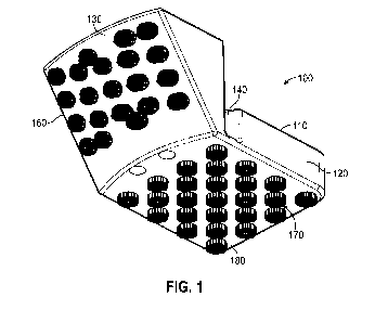
[0032] Figure 1 shows a lower perspective view of a brush in accordance
with this
disclosure.
[0033] Figure 2 shows an upper perspective view of the brush of FIG. 1.
[0034] Figure 3 shows a sectioned perspective view of a juicer in
accordance with this
disclosure.
[0035] Figure 4 shows a sectioned perspective view of the juicer of FIG.
3 with the brush
of FIG. 1.
[0036] Figure 5 shows a sectioned view of the juicer of FIG. 3 and the
brush of FIG. 1
used in a cleaning method.
[0037] Figure 6 shows an upper perspective view of a second embodiment of
a brush in
accordance with this disclosure.
- 5 -
CA 03206013 2023-06-20
WO 2022/159384 PCT/US2022/012765
[0038] Figure 7 shows a lower perspective view of the brush of FIG. 6.
[0039] Figure 8 shows a side view of the brush of FIG. 6.
[0040] Figure 9 shows a top view of the brush of FIG. 6.
[0041] Figure 10A shows a sectioned side view of a blender with the brush
of FIG. 6.
[0042] Figure 10B shows a sectioned top view of the blender with the
brush assembly of
FIG. 10A.
[0043] Figure 10C shows a lower perspective view of a portion of the
blender including a
vertical chute.
[0044] Figure 11 shows an upper perspective view of a third embodiment of
a brush in
accordance with this disclosure.
[0045] Figure 12 shows a lower perspective view of the brush of FIG. 11.
[0046] Figure 13 shows a side view of the brush of FIG. 11.
[0047] Figure 14 shows a top view of the brush of FIG. 11.
[0048] Figure 15 shows a bottom view of the brush of FIG. 11.
[0049] Figure 16 shows an upper perspective view of a fourth embodiment
of a brush in
accordance with this disclosure.
[0050] Figure 17 shows a lower perspective view of the brush of FIG. 16.
[0051] Figure 18 shows a side view of the brush of FIG. 16.
[0052] Figure 19 shows a bottom view of the brush of FIG. 16.
DETAILED DESCRIPTION OF THE PREFERRED EMBODIMENTS
[0053] The description of illustrative embodiments according to
principles of the present
disclosure is intended to be read in connection with the accompanying
drawings, which are to be
considered part of the entire written description. In the description of
embodiments of the
disclosure disclosed herein, any reference to direction or orientation is
merely intended for
convenience of description and is not intended in any way to limit the scope
of the present
- 6 -
CA 03206013 2023-06-20
WO 2022/159384 PCT/US2022/012765
disclosure. Relative terms such as "lower," "upper," "horizontal," "vertical,"
"above," "below,"
"up," "down," "top" and "bottom" as well as derivative thereof (e.g.,
"horizontally,"
"downwardly," "upwardly," etc.) should be construed to refer to the
orientation as then described
or as shown in the drawing under discussion. These relative terms are for
convenience of
description only and do not require that the apparatus be constructed or
operated in a particular
orientation unless explicitly indicated as such.
Terms such as "attached," "affixed,"
"connected," "coupled," "interconnected," and similar refer to a relationship
wherein structures
are secured or attached to one another either directly or indirectly through
intervening structures,
as well as both movable or rigid attachments or relationships, unless
expressly described
otherwise. Moreover, the features and benefits of the disclosure are
illustrated by reference to
the exemplified embodiments. Accordingly, the disclosure expressly should not
be limited to
such exemplary embodiments illustrating some possible non-limiting combination
of features
that may exist alone or in other combinations of features; the scope of the
disclosure being
defined by the claims appended hereto.
[0054] This disclosure describes the best mode or modes of practicing the
disclosure as
presently contemplated. This description is not intended to be understood in a
limiting sense, but
provides an example of the disclosure presented solely for illustrative
purposes by reference to
the accompanying drawings to advise one of ordinary skill in the art of the
advantages and
construction of the disclosure. In the various views of the drawings, like
reference characters
designate like or similar parts.
[0055] It is important to note that the embodiments disclosed are only
examples of the
many advantageous uses of the innovative teachings herein. In general,
statements made in the
specification of the present application do not necessarily limit any of the
various claimed
disclosures. Moreover, some statements may apply to some inventive features
but not to others.
In general, unless otherwise indicated, singular elements may be in plural and
vice versa with no
loss of generality.
[0056] Figures 1 and 2 shows perspective views of a brush 100 in
accordance with this
disclosure. Figure 3 shows a sectioned perspective view of a juicer 300 in
accordance with this
- 7 -
CA 03206013 2023-06-20
WO 2022/159384 PCT/US2022/012765
disclosure. Figure 4 shows a sectioned perspective view of the juicer 300 of
FIG. 3 with the
brush 100 of FIG. 1.
[0057] FIG. 1 shows a brush 100 for cleaning a juicer 300. Typically, the
brush 100
shown is removable from a juicer 300 being cleaned, such that during use as a
juicer, the brush is
not present, and the brush is then inserted for use in a cleaning method.
Figure 5 shows a
sectioned view of the juicer 300 of FIG. 3 and the brush 100 of FIG. 1 used in
a cleaning
method, discussed in more detail below.
[0058] As shown, the brush 100 has a brush body 110 having a horizontal
base
component 120 and a first outer brushing surface 130 angled relative to the
horizontal base
component. The horizontal base component 120 extends laterally from the first
outer brushing
surface 130.
[0059] As shown, the brush 100 also includes multiple bristles 160
extending from the
first outer brushing surface 130. In some embodiments, additional bristles 170
extend from a
bottom surface 180 of the horizontal base component 120.
[0060] The brush 100 also has a groove 140 in an upper surface 150 of the
brush body
110, the groove arranged perpendicular to the horizontal base component 120.
The groove 140
is typically located at a transition between the horizontal base component 120
and the first outer
brushing surface 130.
[0061] Typically, the groove 140 forms an arc, as shown. Similarly, the
first outer
brushing surface 130 also forms an arc, when viewed from above or below, and
therein defines a
segment of a surface of a truncated cone. The truncated cone of the first
outer brushing surface
130 and the arc of the groove 140 are centered about an identical central axis
500, 1000 most
clearly visible in FIGS. 5 and 10B.
[0062] Figure 3 shows a juicer 300 for use with the brush 100 of FIG. 1,
FIG. 4 shows
the juicer 300 with the brush incorporated, and FIG. 5 shows the juicer 300
during a cleaning
cycle. As shown, the juicer 300 has a bowl 310 having a substantially circular
flat bottom 320
and mesh walls 330 defining a truncated cone extending from the flat bottom.
- 8 -
CA 03206013 2023-06-20
WO 2022/159384 PCT/US2022/012765
[0063] The juicer 300 further includes a blade 340 located at the flat
bottom 320 of the
bowl 310. A substantially cylindrical vertical chute 350 extends downward into
the bowl 310
and terminates above the blade 340, leaving a small gap 355 between an end 360
of the vertical
chute 350 and the flat bottom 320 of the bowl.
[0064] During use, the blade 340 rotates with the bowl 310, thereby
chopping any
produce that is inserted into the vertical chute 350. Once the produce has
been chopped
sufficiently finely, it passes through the small gap 355 between the end 360
of the vertical chute
350 and the flat bottom 320 of the still rotating bowl 310 and is pressed
against the conical mesh
walls 330 by centrifugal force of the rotation, thereby straining fruit juice
through the mesh
walls.
[0065] During a cleaning routine, the juicer 300 is opened and the
removable brush 100
is inserted. During insertion, the groove 140 of the removable brush 100 is
mated with the end
360 of the vertical chute 350. The arc of the groove 140 typically corresponds
to the
circumference of the end 360 of the vertical chute 350 such that the
components are mated by
simply inserting the end of the vertical chute into the groove.
[0066] The juicer 300 is then closed with the brush 100 fitted to the end
360 of the
vertical chute 350. As shown, and as discussed above, the first outer brushing
surface 130 is
angled relative to the horizontal base 120 and defines a segment of a
truncated cone. A slope
angle of the first outer brushing surface 130 is substantially identical to a
slope angle of the mesh
walls 330 of the bowl 310. When inserted into the juicer 300 and mated with
the vertical chute
350, the truncated cone of the first outer brushing surface 130 and the
truncated cone of the mesh
walls 330 of the bowl 310 share the single central axis 500 of the vertical
chute 350.
[0067] The juicer 300 further includes a plunger 370. During typical use
of the juicer
300, the plunger may be used to force produce down the vertical chute 350 such
that it is forced
against the blade 340. During the cleaning routine noted above, the plunger
370 may be used as
a reservoir for water, or some other fluid, which is then poured into the
vertical chute 350 while
rotating the bowl 310 relative to the vertical chute. As such, the brush 100
cleans the bowl 310
while the fluid poured in lubricates the cleaning process. In some
embodiments, the plunger 370
- 9 -
CA 03206013 2023-06-20
WO 2022/159384 PCT/US2022/012765
is provided with a lid 380 such that the plunger is closed during standard use
of the juicer 300.
In such embodiments, the lid 380 is removed so that the plunger 370 can be
used as a reservoir.
[0068] Figure 6 shows an upper perspective view of a second embodiment of
a brush 600
in accordance with this disclosure. Figure 7 shows a lower perspective view of
the brush 600 of
FIG. 6. Figures 8 and 9 show side and top views of the brush 600 of FIG. 6. To
the extent that
the brush 600 of FIG. 6 has components identical to those of the brush 100 of
FIG. 1, the
embodiments use the same reference numerals.
[0069] Figure 10A shows a sectioned side view of a blender 1010 with the
brush 600 of
FIG. 6. Figure 10B shows a sectioned top view of the blender 1010 with the
brush 600 of FIG.
10A. Figure 10C shows a lower perspective view of a portion of the blender
1010 of FIG. 10A
including a vertical chute 1020.
[0070] As shown, the brush 600 may have a brush body 610 further
comprising a
secondary outer brushing surface 630 opposite the horizontal base component
120 from the first
outer brushing surface 130. The secondary outer brushing surface 630 would
typically define a
second segment of the surface of the same truncated cone as that of the first
outer brushing
surface 130. It is noted that in some embodiments, such as that shown in FIG.
6, the secondary
brushing surface 630 does not contain bristles and functions primarily for
stabilizing the brush
600 during use. In other embodiments, such as those shown in FIGS. 11 and 16,
the secondary
brushing surface 630 contains bristles and brushes the bowl of the juicer 300,
1000 during use. It
is further noted that in the embodiments of FIGS. 6, 11, and 16, bristles are
not shown, but
openings 620 for bristles are provided. In use, bristles would typically be
provided in some or all
of the openings for bristles.
[0071] Further, the brush 600 may include a secondary groove 640 in the
upper surface
150 of and perpendicular to the horizontal base component 120 and located at a
transition
between the horizontal base component and the secondary outer brushing surface
630.
Accordingly, the secondary groove 640 is opposite the horizontal base
component 120 from the
first outer brushing surface 130. The secondary groove 640 may form an arc
centered about the
central axis 1000, and may thereby form an arc of the same circle as that of
the first groove 140.
- 10 -
CA 03206013 2023-06-20
WO 2022/159384 PCT/US2022/012765
[0072] In some embodiments, the brush 100, 600 further comprises a notch
660
extending from one or both of the grooves 140, 640 in the direction of the
horizontal base
component. This notch 660 may interface with a protrusion 1030 extending from
a circular end
1040 of the vertical chute 1020. As such, the circular end 1040 of the
vertical chute 1020 may
mate with the grooves 140, 640 of the brush 100, 600, and the notch 660 may
mate with the
protrusion 1030. During use, the brush 100, 600 is held stationary relative to
the vertical chute
1020 and a bowl of the juicer 1010, and the interface of the notch 660 and the
protrusion 1030
prevents the brush 100, 600 from rotating relative to the vertical chute 1020.
[0073] It is noted that the embodiment shown provides a notch 660
extending from the
secondary groove 640 and a protrusion 1030 extending from the circular end
1040 of the vertical
chute 1020. However, it is understood that the notch 660 may be provided in
the first groove
140 in addition to or in place of the secondary groove 640. Similarly, the
locating mechanism
may be modified such that, for example, a notch is provided in the circular
end 1040 of the
vertical chute, and a discontinuity is provided in one or both of the grooves
140, 640 in order to
mate with the notch.
[0074] Figure 11 shows an upper perspective view of a third embodiment of
a brush 1100
in accordance with this disclosure. Figure 12 shows a lower perspective view
of the brush 1100
of FIG. 11. Figure 13 shows a side view of the brush 1100 of FIG. 11. Figure
14 shows atop
view and FIG. 15 shows a bottom view of the brush 1100 of FIG. 11.
[0075] The brush of FIG. 11 is similar to that shown above in FIG. 6, and
is labeled using
identical reference numerals for parallel features. As shown, the embodiment
shown differs
from those discussed above in that no bristles or bristle openings are
provided on the bottom
surface 180 of the horizontal base component 120.
[0076] Further, as shown, the secondary outer brushing surface 630 may be
provided
with openings for bristles 1110 similar to those, and in addition to those
620, provided on the
first brushing surface 130.
[0077] Further, while the bristles 160 shown in FIG. 1 and the openings
for bristles
shown in FIG. 6 are shown as perpendicular to the surface 130 of the first
outer brushing surface
-11-
CA 03206013 2023-06-20
WO 2022/159384 PCT/US2022/012765
130, the bristle openings 620, 1110 of the brush 1100 of FIG. 11 is instead
angled relative the
first and second outer brushing surfaces 130, 630. The openings 620, 1110 of
the brush 1100 are
instead parallel to the grooves 140, 640 in the brush 1100 so that they face
straight downward
during use.
[0078] Figure 16 shows an upper perspective view of a fourth embodiment
of a brush
1600 in accordance with this disclosure. Figure 17 shows a lower perspective
view of the brush
1600 of FIG. 16. Figure 18 shows a side view of the brush 1600 of FIG. 16.
Figure 19 shows a
bottom view of the brush 1600 of FIG. 16.
[0079] As noted above with respect to the brush 1100 of FIG. 11, the
brush 1600 is also
similar to the other embodiments shown, but provides a few distinct features.
As shown, the
brush 1600 provides a secondary horizontal base surface 1610. Such a base
surface is above the
lower surface 180 of the horizontal base component 120 of the brush body 610
and may be
adjacent the first or secondary outer brushing surface 130, 630.
[0080] In addition to incorporating bristles 160, or bristle openings
620, into the first or
second outer brushing surface 130, 630, the secondary horizontal base surface
1610 may be
provided with additional bristles or bristle openings 1620. As shown, the
secondary horizontal
base surface 1610 may form a step between the lower surface 180 and the first
or secondary
outer brushing surface 130, 630.
[0081] During use, the brush 100, 600, 1100, 1600 is used by first
removing a cover from
a juicer chamber of the juicer 300, 1010. The juicer cover includes the
substantially cylindrical
vertical chute 350, 1020 and the juicer chamber includes the bowl 310 with the
substantially
circular flat bottom 320 and mesh walls 330 defining a truncated cone.
[0082] The brush 100, 600, 1100, 1600 to be used is then provided, with
the brush taking
the form discussed above. One or both of the groove 140 and the secondary
groove 640 are then
mated to the vertical chute 350, 1020 by locating an end 360, 1040 of the
vertical chute at least
partially within the corresponding groove or grooves. In embodiments including
a notch 660, the
notch is aligned with a protrusion 1030 of the end 360, 1040 of the vertical
chute 350, 1020
when the end is being located within the groove 140, 640.
- 12 -
CA 03206013 2023-06-20
WO 2022/159384 PCT/US2022/012765
[0083] The vertical chute 350, 1020 may then be located so that it shares
a vertical axis
500, 1000 with the mesh walls 330 of the bowl 310. This may be by fixing the
juicer cover
relative to the juicer chamber in order to reassembly the juicer 300, 1010.
[0084] Once the juicer 300, 1010 is fully assembled with the brush 100,
600, 1100, 1600
properly inserted, a cleaning routine may be executed during which the bowl
310 is rotated
relative to the vertical chute 350, 1020 and the brush. Typically, during this
part of the process, a
fluid, such as water is poured into the vertical chute 350, 1020 in order to
lubricate the cleaning
process.
[0085] While the present disclosure has been described at some length and
with some
particularity with respect to the several described embodiments, it is not
intended that it should
be limited to any such particulars or embodiments or any particular
embodiment, but it is to be
construed with references to the appended claims so as to provide the broadest
possible
interpretation of such claims in view of the prior art and, therefore, to
effectively encompass the
intended scope of the disclosure.
[0086] All examples and conditional language recited herein are intended
for pedagogical
purposes to aid the reader in understanding the principles of the disclosure
and the concepts
contributed by the inventor to furthering the art, and are to be construed as
being without
limitation to such specifically recited examples and conditions. Moreover, all
statements herein
reciting principles, aspects, and embodiments of the disclosure, as well as
specific examples
thereof, are intended to encompass both structural and functional equivalents
thereof.
Additionally, it is intended that such equivalents include both currently
known equivalents as
well as equivalents developed in the future, i.e., any elements developed that
perform the same
function, regardless of structure.
- 13 -