Note: Descriptions are shown in the official language in which they were submitted.
WO 2022/216298
PCT/US2021/027997
AUTOMATIC DIGITAL ROCK SEGMENTATION
CROSS-REFERENCE TO RELATED APPLICATIONS
[0001] This application claims priority to U.S. Non-Provisional
Patent Application No.
17/227,005 filed April 9, 2021, the disclosure of which is hereby incorporated
by reference.
FIELD OF THE DISCLOSURE
[0002] The present disclosure relates generally to
characterization of a reservoir rock
sample (e.g., a core sample or plug sample) and particularly, to automatic
digital
segmentation of image data of the sample using a trained deep learning model.
BACKGROUND
[0003] To characterize a subsurface reservoir formation, a rock
sample (e.g., a core
sample or a plug sample) may be extracted from the formation. Once extracted,
properties
of the sample may be measured and scaled (e.g., extrapolated) to estimate
properties of the
reservoir formation. In some cases, the properties of the sample may be
determined or
is measured based on physical manipulations of the sample. For instance,
portions of the
sample may be removed, cut, sanded, treated, and/or the like to determine a
porosity of the
sample, a distribution of minerals within the sample, or a distribution of
porous media within
the sample, among other properties. Such physical manipulations may limit the
usability
and/or lifespan of the core sample, as they may alter or otherwise make the
core sample
unsuitable for further testing or analysis. Further, acquisition of a
subsequent core sample
for additional testing may be costly in terms of time and resources (e.g.,
drilling equipment).
[0004] Accordingly, in some cases, the properties of the sample
may be determined
based on images (e.g., imaging data) of the sample. For instance, computed
tomography
(CT) images may depict internal features of the sample without requiring those
features to
be physically exposed (e.g., via cutting or sanding), which may extend the
lifetime of the
core sample. However, identification of specific features, such as pores,
porous medium,
or minerals within such images may be time-consuming and difficult. A.dditiona
fly,
variations between imaging conditions, including differences in equipment used
to obta in
images of a rock sample, may result in the same or similar features of the
physical rock being
depicted inconsistently across different images of the same sample.
1
CA 03206096 2023- 7- 21
WO 2022/216298
PCT/US2021/027997
BRIEF DESCRIPTION OF THE DRAWINGS
[0005] FIG. 1 is a diagram of an illustrative drilling system in
which embodiments of
the present disclosure may be implemented.
[0006] FIG. 2A is an image of a reservoir rock sample, in
accordance with embodiments
of the present disclosure.
[0007] FIG. 2R is the image of the reservoir rock sample in FIG.
2A after being
segmented into multiple channels corresponding to different regions of
reservoir rock, in
accordance with embodiments of the present disclosure.
[0008] FIG. 3 is a block diagram of an illustrative system in
which embodiments of the
to present disclosure may be implemented.
[0009] FIG. 4 is a flowchart of an illustrative process for
automatic digital rock
segmentation using a deep learning model, in accordance with embodiments of
the present
disclosure.
[0010] FIG. 5 is a flowchart of an illustrative process for
training a deep learning model,
is in accordance with embodiments of the present disclosure.
[0011] FIG. 6A is a segmented multi-channel image of a reservoir
rock sample, in
accordance with embodiments of the present disclosure.
[0012] FIGS. 6B-6C illustrate binary images respectively
corresponding to a particular
channel of the segmented multi-channel image of FIG. 6A, in accordance with
embodiments
zo of the present disclosure.
[0013] FIG. 7A is a multi-channel image of a reservoir rock
sample, in accordance with
embodiments of the present disclosure.
[0014] FIGS. 7B-7C illustrate binary images respectively
corresponding to a particular
channel of the multi-channel image of FIG. 7A, in accordance with embodiments
of the
25 present disclosure.
[0015] FIG. 8 is a block diagram of an illustrative computer
system in which
embodiments of the present disclosure may be implemented.
DESCRIPTION OF ILLUSTRATIVE EMBODIMENTS
[0016] Embodiments of the present disclosure relate to automatic
digital segmentation
30 of reservoir rock samples, such as a core or a plug sample. NI:ore
specifically, the present
disclosure relates to digital segmentation of the reservoir rock samples using
a deep learning
model (e.g., a machine learning algorithm), such as a three-dimensional (3D) U-
net model.
2
CA 03206096 2023- 7- 21
WO 2022/216298
PCT/US2021/027997
While the present disclosure is described herein with reference to
illustrative embodiments
for particular applications, it should be understood that embodiments are not
limited thereto.
Other embodiments are possible, and modifications can be made to the
embodiments within
the spirit and scope of the teachings herein and additional fields in which
the embodiments
would be of significant utility. Further, when a particular feature,
structure, or characteristic
is described in connection with an embodiment, it is submitted that it is
within the knowledge
of one skilled in the relevant art to implement such feature, structure, or
characteristic in
connection with other embodiments whether or not explicitly described.
[0017] It would also be apparent to one of skill in the relevant
art that the embodiments,
as described herein, can be implemented in many different embodiments of
software,
hardware, firmware, and/or the entities illustrated in the figures. Any actual
software code
with the specialized control of hardware to implement embodiments is not
limiting of the
detailed description. Thus, the operational behavior of embodiments will be
described with
the understanding that modifications and variations of the embodiments are
possible, given
Is the level of detail presented herein.
[0018] In the detailed description herein, references to "one
embodiment," "an
embodiment," "an example embodiment," etc., indicate that the embodiment
described may
include a particular feature, structure, or characteristic, but every
embodiment may not
necessarily include the particular feature, structure, or characteristic.
Moreover, such
zo phrases are not necessarily referring to the same embodiment.
[0019] As will be described in further detail below, embodiments
of the present
disclosure may be used to segment (e.g., classify) regions of an image of a
reservoir rock
sample, such as a core sample or a plug sample, using a deep learning model
(e.g., a machine
learning algorithm). More specifically, embodiments, of the present disclosure
relate to
25 training and using a deep learning model, such as a neural network, to
automatically segment
an image of a reservoir rock sample into different channels (e.g., classes
and/or labels). The
different channels may include a channel corresponding to a mineral (e.g., a
mineral
channel), a channel corresponding to a porous medium (e.g., a porous medium
channel.), a
channel corresponding to a pore (e.g., a pore channel), and/or the like. In
this regard, the
30 segmentation of an image of a reservoir rock sample may involve
indicating that a region of
the image depicting a mineral is associated with the mineral channel, a region
of the image
depicting a porous medium (e.g., a porous phase) is associated with the porous
medium
channel, a region of the image depicting a pore is associated with the pore
channel, and/or
3
CA 03206096 2023- 7- 21
WO 2022/216298
PCT/US2021/027997
the like. Moreover, automatically segmenting the image with the deep learning
model may
involve segmenting the image without user intervention (e.g., without a user
input and/or
without a user-designated segmentation).
[0020] In some embodiments, the automatic segmentation of image
data by the deep
learning model may map and/or convert intensities (e.g., pixel intensities
and/or pixel values)
within an image (e.g., image data) to a particular channel. The intensities
may correspond
to a measure of signal intensity associated with an image element (e.g., a
pixel and/or a
voxel) of the image data and/or a level of brightness associated with the
image element in a
grayscale or color image of the image data. As an illustrative example of the
intensity
it) mapping, an image element (e.g., a region of the image), such as a
pixel and/or a voxel, with
a relatively higher intensity (e.g., within a first range of intensity values
or "first intensity
range") may be characterized (e.g., segmented) as being associated with a
first channel (e.g.,
a mineral channel), while an image element with a relatively lower intensity
(e.g., within a
second intensity range) may be characterized as being associated with a second
channel (e.g.,
Is a pore channel). Continuing with the above example, an image element
with an intensity
falling between the first and second intensity ranges associated with the
respective mineral
and pore channels may be characterized as being associated with a third
channel (e.g., a
porous medium channel). It should be appreciated that the third channel may be
associated
with a third intensity range with intensity values falling between those
associated with the
20 first and second ranges of the respective first and second channels.
Moreover, in some
embodiments, the segmentation by the deep learning model may account for
variations in
intensities of similar features (e.g., minerals, pores, porous medium, and/or
the like) between
different images, which may result from differences in equipment and/or
imaging modalities
used to obtain the images, for example. To that end, the deep learning model
may perform
25 the segmentation such that a first image of a rock sample obtained under
first conditions
(e.g., using first equipment) may be segmented with substantially the same
results (e.g.,
output channels) as a second image of the rock sample obtained under second
conditions
(e.g., using second equipment).
[0021] Further, in some embodiments, the segmentation generated
by the deep learning
30 model may be provided as a set of binary images, where the set includes
a different binary
image for each channel included in the segmentation. For instance, for an
image with a
region characterized as depicting a mineral and a region characterized as
depicting a pore,
the segmentation may include a first binary image corresponding to the mineral
channel and
4
CA 03206096 2023-7-21
WO 2022/216298
PCT/US2021/027997
a second, different binary image corresponding to the pore channel.
Additionally or
alternatively, the segmentation and/or a characterization of the image data
may be used to
provide one or more metrics associated with the reservoir rock sample. For
instance, the
segmentation may be used to provide an indication of a distribution of pores,
minerals, and/or
porous medium in the reservoir rock sample, a size of the pores, minerals,
and/or porous
medium in the reservoir rock sample, a model of the reservoir rock sample,
and/or the like
In this regard, the indication may be a numerical indication, a graphical
indication, a textual
indication, or a combination thereof. Moreover, in some embodiments, the
indication may
be used to model and/or simulate further properties of the reservoir rock
sample. For
instance, fluid flow through the reservoir rock sample may be simulated based
on the
indication.
100221 In some embodiments, training the deep learning model may
involve obtaining
training image data, as well as training segmentation data associated with the
training image
data. The training image data may include images of reservoir rock samples,
and the training
I s segmentation data may include a respective segmentation (e.g.,
designations of channels)
associated with each of the images. In some embodiments, for a particular
image of the
training image data, the training segmentation data may include a composite
image that
includes one or more segmentations (e.g., channel outputs). In such
embodiments, the
composite image may be separated into a set of binary images, where the set
includes a
different binary image for each channel output. In some embodiments, for a
particular image
of the training binary image, the training segmentation data may include a set
of binary
images respectively corresponding to a particular channel of the particular
image. In such
embodiments, the training segmentation data may not be further separated. In
any case,
training the deep learning model may involve training the deep learning model
based on
associations between the training image data and the training segmentation
data. That is, for
example, the deep learning model may be trained based on a mapping between an
input
training image of the training image data and an output of an associated
training
segmentation data (e.g., channel outputs associated with the input image).
Thus, in some
embodiments, the deep learning model may be trained via supervised learning.
Moreover,
in some embodiments, the training of the deep learning model may be validated
by a user
(e.g., via a user input) and/or based on a set of validation data, and the
deep learning model
may be retrained and/or the training of the deep learning model may be
adjusted based on
the validation.
5
CA 03206096 2023- 7- 21
WO 2022/216298
PCT/US2021/027997
[0023] Illustrative embodiments and related methodologies of the
present disclosure are
described below in reference to FIGS. 1-8 as they might be employed in, for
example, a
computer system for well planning. Advantages of the disclosed automatic
digital rock
segmentation techniques include, for example and without limitation,
characterization of
reservoir rock samples and, as a result, of a reservoir with greater
consistency and/or
accuracy. For instance, the disclosed automatic segmentation may reduce user
errors
associated with manual segmentation. Further, by digitally segmenting a rock
sample, the
rock sample may be characterized without physically manipulating (e.g.,
removing portions
of, cutting, sanding, treating, and/or the like) the rock sample itself In
this regard, the same
to rock sample may be used repeatedly and/or for a number of different
simulations. In this
way, the number of rock samples retrieved from a reservoir, which may involve
a costly and
time-intensive process, may be reduced.
[0024] Other features and advantages of the disclosed
embodiments will be or will
become apparent to one of ordinary skill in the art upon examination of the
following figures
is and detailed description. It is intended that all such additional
features and advantages be
included within the scope of the disclosed embodiments. Further, the
illustrated figures are
only exemplary and are not intended to assert or imply any limitation with
regard to the
environment, architecture, design, or process in which different embodiments
may be
implemented.
20 10025] FIG. 1 is a diagram of an illustrative drilling system. In
accordance with the
present disclosure, the drilling system may be used to retrieve a reservoir
rock sample, such
as a core sample, for characterization of a reservoir. As shown in Fla 1, a
drilling platform
100 is equipped with a derrick 102 that supports a hoist 104. Drilling in
accordance with
some embodiments is carried out by a string of drill pipes connected together
by -tool" joints
25 so as to form a drill string 106. Hoist 104 suspends a top drive 108
that is used to rotate drill
string 106 as the hoist lowers the drill string through wellhead 110.
Connected to the lower
end of drill string 106 is a reservoir rock sample collection tool 112, such
as a drill bit and/or
a coring tool. The reservoir rock sample collection tool 112 may retrieve a
reservoir rock
sample by cutting (e.g., drilling) the sample from a reservoir formation 113
and/or any other
30 suitable method to extract the sample. In some embodiments, the sample
may be cut from a
side of the wellbore 122. Further, in some embodiments, to drill and/or cut
the sample, the
reservoir rock sample collection tool 112 is rotated and collection of the
sample and/or
drilling of a wellbore 122 is accomplished by rotating drill string 106, e.g.,
by top drive 108
6
CA 03206096 2023- 7- 21
WO 2022/216298
PCT/US2021/027997
or by use of a downhole "mud" motor (not shown) near reservoir rock sample
collection tool
112 (e.g., drill bit) that turns the tool or by a combination of both top
drive 108 and a
downhole mud motor. Further, in some embodiments, a hollow chamber may be
connected
to the lower end of the drill string 106 such that a reservoir rock sample cut
and/or drilled by
the reservoir rock sample collection tool 112 may be extracted into the hollow
chamber and
subsequently retrieved from the wellbore 122 (e.g., via retrieval of the
hollow chamber
and/or the drill string 106).
100261 Thus, as illustrated, the reservoir rock sample 115 may
be retrieved (e.g.,
collected) from the wellbore 122 and/or reservoir formation 113. In some
embodiments, the
to reservoir rock sample 115 may be a core sample or a plug sample. As
described herein, the
term core sample may refer to a reservoir rock sample retrieved directly from
a wellbore
(e.g., wellbore 122) and/or reservoir formation. In some embodiments a core
sample may
be generally cylindrical in shape. M:oreover, a core sample may include first
dimensions
(e.g., a first diameter and a first length). In some embodiments, a diameter
and/or a length
Is of the core sample may be on the order of tens to hundreds of feet.
Further, as described
herein, the term plug sample may refer to a reservoir rock sample taken from a
core sample
(e.g., after the core sample is removed from the wellbore 122). In some
embodiments, a plug
sample may include second dimensions different than the first dimensions. For
instance, a
plug sample may have a diameter and/or length on the order of inches or feet.
While
20 particular dimensions are described with reference to core samples and plug
samples,
embodiments are not limited thereto. In this regard, a core sample or a plug
sample may
have any suitable dimensions.
[0027] As described in greater detail below, a retrieved
reservoir rock sample 115 may
be used to characterize certain properties of the reservoir formation 113. In
some
25 embodiments, for example, the retrieved reservoir rock sample 115 may be
analyzed to
determine a porosity of the reservoir formation 113, a presence of certain
minerals within
reservoir formation 113, an expected fluid flow within of the reservoir
formation 113 and/or
the like. In some embodiments, such analysis may be performed by physically
manipulating
(e.g., cutting, coring, and/or the like). Additionally or alternatively, the
reservoir rock
30 sample 115 may be imaged, and the resulting image data may be analyzed
to determine
characteristics of the reservoir formation 113. As illustrated, for example,
an imaging scan
117 may be performed on the reservoir rock sample 115.
7
CA 03206096 2023- 7- 21
WO 2022/216298
PCT/US2021/027997
[0028] In some embodiments, the imaging scan 117 may capture
image data of the
reservoir rock sample 115. In some embodiments, the image data may include a
sequence
of two-dimensional images of the reservoir rock sample 115 that together form
three-
dimensional image data of the reservoir rock sample 115. Further, the image
data may
include a computed tomography (CT) image, a magnetic resonance imaging (MRI)
image,
an ultrasound image, and/or the like. To that end, the imaging scan 117 may be
performed
by any suitable imaging device. In some embodiments, a computed tomography
(..c,T)
imaging device, a rnicroCT imaging device, an MM imaging device, an ultrasound
imaging
device, and/or the like may be used to perform the imaging scan 117, for
example. In some
to embodiments, a CT imaging device may be used to capture image data of a
reservoir rock
sample 115 that is a core sample, while a microCT imaging device may be used
to capture
image data of a reservoir rock sample 115 that is a plug sample. Further, the
microCT
imaging device may capture image data of the plug sample with a higher
resolution than the
image data of the core sample captured by the CT imaging device.
Is [0029] While the reservoir rock sample 115 and imaging scan 117 are
illustrated
proximate the drilling platform .100, it may be appreciated that the reservoir
rock sample 115
may be transported off location for the imaging scan 117. In this regard, the
imaging scan
117 may be performed within a laboratory or a separate geographical location
from the
drilling platform 100 and/or a field location. Additionally or alternatively,
the imaging scan
zo 117 may be performed in the field (e.g., proximate the wellsite).
[0030] As further illustrated, the results of the imaging scan
117 (e.g., the image data
produced by the imaging scan 117) may be provided to a processing system 119
(e.g., a
computing system). The processing system 119 may perform one or more of the
techniques
described herein to characterize the image data of the reservoir rock sample
115 and, as a
25 result, to characterize the reservoir formation 113. In particular, the
processing system 119
may use and/or implement a deep learning model (e.g., a machine learning
algorithm) to
automatically segment the image data, as described below with respect to at
least FIGS. 3
and 4.
[0031] In som.e embodiments, the processing system 119 may be
implemented using any
30 type of processing system, such as computer system 800 of FIG. 8
described below. In some
embodiments, the processing system computing device having at least one
processor and a
memory, such as memory 121.
8
CA 03206096 2023- 7- 21
WO 2022/216298
PCT/US2021/027997
[0032] As illustrated, the processing system 119 may be in
communication with a
memory 121. The memory 121 may be any suitable data storage device.
Additionally or
alternatively, the memory 121 may be any type of recording medium coupled to
an integrated
circuit that controls access to the recording medium. The recording medium can
be, for
example and without limitation, a semiconductor memory, a hard disk, or
similar type of
memory or storage device In some implementations, memory 121 may be a remote
data
store, e.g., a cloud-based storage location. The memory 121 may be internal to
or external
to the processing system 119.
[0033] In some embodiments, the memory 121 may include training
data suitable to train
the deep learning model used by the processing system 119, as described below
with
reference to FIG. 5. Segmentation data generated by the processing system 119
may further
be stored in the memory 121.
[0034] FIG. 2A is an exemplary image 200 of a reservoir rock
sample, such as a core
sample or a plug sample. In particular, the image ZOO is a CT image of a
reservoir rock
is sample. The image 200 includes regions illustrated with different
intensities (e.g., shown as
different colors within a grayscale coding). In some embodiments, regions with
different
intensities within an image of a reservoir rock sample, such as image 200, may
correspond
to different channels, or classes. For instance, an image of a reservoir rock
sample may
depict a pore, a porous medium, a mineral, and/or the like. As described
herein, the term
zo porous medium (e.g., porous phase) can refer to types of rocks with a
relatively greater
porosity than a mineral. For instance, limestone, sandstone, and/or the like
may correspond
to the porous medium channel. As described herein, the term pore can refer to
empty space
(e.g., gaps) within a reservoir rock sample, such as gaps between minerals
and/or porous
medium. Further, the image 200 may be referred to as a multi-class or multi-
channel image,
25 as the image 200 depicts multiple different channels (e.g., multiple
classes). To that end, the
image 200 depicts at least one pore, porous medium, and mineral, which each
correspond to
a different channel (e.g., a pore channel, a porous medium channel, and a
mineral channel,
respectively).
[0035] In some embodiments, an image of a reservoir rock sample
may be segmented
30 into the different channels included within the image. That is, for
example, areas of the
image may be classified and/or labeled according to the channel with which
they correspond.
In some embodiments, such segmentation may be performed based on a user input.
For
instance, a user may provide an input to select an area (e.g., a point) of the
image and to
9
CA 03206096 2023- 7- 21
WO 2022/216298
PCT/US2021/027997
indicate that the area corresponds to a particular channel. With respect to
FIG. 2A, for
example, a user may provide inputs 202a-d to indicate that the areas
corresponding to the
inputs 202a-d correspond to a mineral. The input 204 may be provided to
indicate an area
corresponding to a porous medium, and the input 206 may be provided to
indicate an area
corresponding to a pore.
[0036] In some embodiments, a user input, such a s inputs 202a-
d, 204, and 206, may be
provided at a particular point within an image, as illustrated. In such cases,
segmentation of
the image may involve identifying an extent of an area including the point
that corresponds
to a particular channel. For instance, an area with similar properties to the
point may be
identified as corresponding to the same channel as the point. In some
embodiments, to
identify the area, image processing may be utilized to identify image elements
(e.g., pixels)
with a matching or substantially similar intensity as the points that are
adjacent to or in
communication with the point. In this regard, the segmentation and/or image
processing
may involve a pixel level analysis. Additionally or alternatively, an area
surrounding and/or
is including the point may be identified based on identification of edges
of the area. The edges
may be identified based on a difference in intensities between adjacent pixels
or lines within
an image exceeding a threshold, for example. Moreover, embodiments are not
limited to the
image processing techniques described herein. In this regard, any suitable
segmentation
and/or image analysis techniques may be employed to segment an image based on
a user
input.
[0037] FIG. 2B illustrates an image 220 segmented into different
channels. More
specifically, FIG. 213 corresponds to a segmentation of the image 200 based on
the inputs
202a-d, 204, and 206. To that end, the regions 222a-d, which may be identified
based on the
user inputs 202a-d, are shown as corresponding to the mineral channel via a
first fill pattern.
The region 224, which may be identified based on the user input 204, is shown
as
corresponding to the porous medium channel via a second fill pattern, and the
region 226,
which may be identified based on the user input 206, is shown as corresponding
to the pore
channel via a third fill pattern.
[0038] In some embodiments, a user input for segmentation of an
image may
additionally or alternatively indicate an outline of an area corresponding to
a particular
channel. In this regard, the any of the regions 222a-d, 224, or 226 may be
determined based
on image processing associated with a user input corresponding to a point
(e.g., user inputs
202a-d, 204, or 206, respectively) or may be determined based on an outline of
the region
CA 03206096 2023- 7- 21
WO 2022/216298
PCT/US2021/027997
indicated by a user input. In any case, such segmentation of an image is
dependent on a user
input, such as an input provided by a geologist. Accordingly, the segmentation
illustrated
and described with respect to FIGS. 2A-2B may be both time consuming and
imprecise (e.g.,
susceptible to error). For instance, analysis of a reservoir rock sample may
be delayed based
on the time it takes for a user to perform manual selections (e.g., provide
user inputs) within
each image of a set of image data corresponding to the sample. To that end,
with increasing
image data for a reservoir rock sample, the analysis time may also increase.
Moreover,
because intensities of image elements within images may vary based on the
imaging
equipment and/or conditions (e.g., resolution, settings, and/or the like) with
which the images
are obtained, segmentation and/or comparison of image elements across
different imaging
equipment and/or conditions may be difficult.
100391 Turning now to FIG. 3, a block diagram of an exemplary
system 300 for
automatic digital characterization (e.g., segmentation) of a reservoir rock
sample is
illustrated. As shown in FIG. 3, system 300 includes a memory 310, a deep
learning model
is 312, a graphical user interface (GUI) 314, a network interface 316, a
data visualizer 318, and
a rock simulator 320. In some embodiments, memory 310, deep learning model
312, GUI
314, network interface 316, data visualizer 318, and rock simulator 320 may be
communicatively coupled to one another via an internal bus of system 300.
Further, in some
embodiments, one or more of the components, functions, and/or operations of
the system
zo 300 may be included within and/or performed by the processing system 119
and/or the
memory 121 of FIG. 1.
[0040] System 300 may be implemented using any type of computing
device having at
least one processor and a memory, such as the processing system 119 of FIG. 1
and/or the
system 800 of FIG. 8. The memory may be in the form of a processor-readable
storage
25 medium for storing data and instructions executable by the processor.
Examples of such a
computing device include, but are not limited to, a tablet computer, a laptop
computer, a
desktop computer, a workstation, a mobile phone, a personal digital assistant
(PDA), a set-
top box, a server, a cluster of computers in a server farm or other type of
computing device.
In some implementations, system 300 may be a server system located at a data
center
30 associated with the hydrocarbon producing field. The data center may be,
for example,
physically located on or near the field. Alternatively, the data center may be
at a remote
location away from the hydrocarbon producing field. The computing device may
also
include an input/output (I/O) interface for receiving user input or commands
via a user input
11
CA 03206096 2023- 7- 21
WO 2022/216298
PCT/US2021/027997
device (not shown). The user input device may be, for example and without
limitation, a
mouse, a QWERTY or T9 keyboard, a touch-screen, a graphics tablet, or a
microphone. The
I/0 interface also may be used by each computing device to output or present
information to
a user via an output device (not shown). The output device may be, for
example, a display
coupled to or integrated with the computing device for displaying a digital
representation of
the information being presented to the user.
[0041] Although only memory 310, deep learning model 312, GUI
314, network
interface 316, data visualizer 318, and rock simulator 320 are shown in FIG.
3, it should be
appreciated that system 300 may include additional components, modules, and/or
sub-
components as desired for a particular implementation. It should also be
appreciated that
memory 310, deep learning model 312, GUI 314, network interface 316, data
visualizer 318,
and rock simulator 320 may be implemented in software, firmware, hardware, or
any
combination thereof. Furthermore, it should be appreciated that embodiments of
memory
310, deep learning model 312, GUI 314, network interface 316, data visualizer
318, and rock
Is simulator 320, or portions thereof, can be implemented to run on any
type of processing
device including, but not limited to, a computer, workstation, embedded
system, networked
device, mobile device, or other type of processor or computer system capable
of carrying out
the functionality described herein.
[0042] As will be described in further detail below, memory 310
can be used to store
information accessible by the deep learning model 312 and/or the GUI 314 for
implementing
the functionality of the present disclosure. While not shown, the memory 310
can
additionally or alternatively be accessed by the data visualizer 318, the rock
simulator 320,
and/or the like. Memory 310 may be any type of recording medium coupled to an
integrated
circuit that controls access to the recording medium. The recording medium can
be, for
example and without limitation, a semiconductor memory, a hard disk, or
similar type of
memory or storage device. In some implementations, memory 310 may be a remote
data
store, e.g., a cloud-based storage location, communicatively coupled to system
300 over a
network 322 via network interface 316 (e.g., a port, a socket, an interface
controller, and/or
the like). Network 322 can be any type of network or combination of networks
used to
communicate information between different computing devices. Network 322 can
include,
but is not limited to, a wired (e.g., Ethernet) or a wireless (e.g., Wi-Fi or
mobile
telecommunications) network. In addition, network 322 can include, but is not
limited to, a
local area network, medium area network, and/or wide area network such as the
Internet.
12
CA 03206096 2023- 7- 21
WO 2022/216298
PCT/US2021/027997
[0043] As shown in FIG. 3, memory 310 may be used to store a
training data 326. The
training data 326 may include image data 330 as well as segmentation data 332
(e.g.,
classification data). In some embodiments, the image data 330 may include
images
associated with reservoir rock samples, such as core samples and/or plug
samples, obtained
via a reservoir formation. For instance, the image data 330 may correspond to
imaging data
output by an imaging scan of' a reservoir rock sample, such as imaging scan
117 of FIG. 1.
In this regard, the image data 330 may include CT image data or image data
corresponding
to any suitable imaging modality. Moreover, the image data 330 may include 2D
images
and/or 3D image data (e.g., a sequence of 21) images). The segmentation data
332 may
to include one or more segmentations of the image data 330. That is, for
example, the
segmentation data 332 may segment (e.g., label and/or classify) different
areas of images
within the image data 330 based on a particular channel associated with the
areas. In this
regard, segmentation data 332 may map an intensity of an image element (e.g.,
an area of an
image) to a particular output channel, where the output channel represents a
characterization
Is of reservoir rock for a corresponding segment of the image data 330. For
instance, the
segmentation data 332 may identify an area (e.g., an image element) of an
image as
corresponding to the pore channel, the porous medium channel, the mineral
channel, and/or
the like. In some embodiments, the segmentation data 332 may be integrated
within or
separate from the image data 330. For instance, the image data 330 may include
segmented
zo images that already include segmentation data 332, such as image 220 of
FIG. 2B.
Additionally or alternatively, the segmentation data may be stored in
association with the
image data 330 and/or may be included in metadata (e.g., a header) of the
image data 330.
Further, in some embodiments, the segmentation data 332 may be generated based
on a
segmentation procedure involving user inputs, as described above with respect
to FIG. 2B,
25 and/or the segmentation data 332 may be generated based on a fully
automatic segmentation
procedure (e.g., a segmentation procedure that does not require user
intervention), as
described in greater detail below.
[0044] In some embodiments, the training data 326 may
additionally or alternatively be
obtained from a database, such as database 324. In particular, the training
data. 326 may be
30 communicated from the database 324 via the network 322 and/or the
network interface 316.
In some embodiments, for example, the training data 326 may be stored within
the memory
310 after it is communicated from the database 324. Database 324 may be any
type of data
storage device, e.g., in the form of a recording medium coupled to an
integrated circuit that
13
CA 03206096 2023- 7- 21
WO 2022/216298
PCT/US2021/027997
controls access to the recording medium. The recording medium can be, for
example and
without limitation, a semiconductor memory, a hard disk, or similar type of
memory or
storage device accessible to system 300. Further, as shown in FIG 3, database
324 may be
implemented as a remote database communicatively coupled to system 300 via
network 322.
[0045] As further illustrated, the system 300 may include sample data 328.
The sample
data 328 may be stored and/or buffered within the memory 310, for example. in
some
embodiments, the sample data 328 may include sample image data 334. The sample
image
data 334 may correspond to image data of a reservoir rock sample, such as
reservoir rock
sample 115 (FIG. 1). For instance, the sample image data 334 may include one
or more
images, such as a sequence of images, of the reservoir rock sample. In some
embodiments,
the images may be CT images of the reservoir rock sample. More specifically,
the images
may include images of an interior of a reservoir rock sample, as imaged by a
CT imaging
device.
[0046] The sample data 328 may further include sample
segmentation data 336. The
Is sample segmentation data 336 may include one or more segmentations of
the sample image
data 334. That is, for example, the sample segmentation data 336 may segment
(e.g., label
and/or classify) different areas of images within the sample image data 334
based on a
particular channel associated with the areas. In this regard, sample
segmentation data 336
may map an intensity of an image element in the sample image data 334 to a
particular output
zo channel, where the output channel represents a characterization of the
reservoir rock for a
corresponding segment of the sample image data 334. For instance, the sample
segmentation
data 336 may identify an area (e.g., an image element) of an image as
corresponding to the
pore channel, the porous medium channel, the mineral channel, and/or the like.
Moreover,
in some embodiments, the sample segmentation data 336 may include a set of
binary images.
25 More specifically, the sample segmentation data 336 may include a
respective set of binary
images for particular images of the sample image data 334. An exemplary set of
binary
images may include a different binary image for each channel included in an
image of the
sample image data 334. For instance, for an image having a first region
corresponding to
the pore channel, a second region corresponding to the porous medium channel,
and the
30 mineral channel, the sample segmentation data 336 may include a first
binary image
depicting the first region, a second binary image depicting the second region,
and a third
binary image depicting the third region.
14
CA 03206096 2023- 7- 21
WO 2022/216298
PCT/US2021/027997
[0047] In some embodiments, the sample segmentation data 336 may
be generated by
the deep learning model 312. As described in greater detail below, the deep
learning model
312 may generate the sample segmentation data 336 based on the sample image
data 334
and the training data 326 (e.g., based on training of the deep learning model
312). Moreover,
once generated, the sample segmentation data 336 may be integrated within or
maintained
separate from the sample image data 334. For instance, the sample segmentation
data 336
may be stored in association with the sample image data 334 and/or may be
included in
metadata (e.g., a header) of the sample image data 334.
[0048] In some embodiments, the deep learning model 312 (e.g., a
machine learning
io algorithm) may be implemented as a neural network. In particular, the
deep learning model
312 may be implemented to output multiple channels. For instance, the deep
learning model
312 may be implemented as a three-dimensional U-Net model with multiple output
channels
(e.g., a multi-net model). The U-Net model is generally characterized by a "U"
shape defined
by dovvnsampling an input (e.g., an input image) to different classes (e.g.,
channels) and then
is upsampling the data back to an original size (e.g., resolution). In this
way, an advantage of
implementing the deep learning model 312 as the 3D Li-Net model is that a
resolution of the
output (e.g., one or more output images) of the 3D U-Net model may
substantially match a
resolution of an input (e.g., an input image) to the model. The deep learning
model 312 may
additionally or alternatively be implemented as a convolutional neural network
(CNN) or
20 any other suitable machine learning algorithm. In some embodiments, the
deep learning
model 312 may be a single model capable of outputting multiple channels. In
some
embodiments, to output multiple different channels, the deep learning model
312 may
include a number of different models (e.g., a different deep learning models).
For instance,
the deep learning model 312 may include a first model configured to output a
first output
25 channel (e.g., associated with segmentation into the first output
channel) and a different,
second model configured to output a second output channel (e.g., associated
with
segmentation into the second output channel). The first model and the second
model may
implemented as the same type of model (e.g., a first 31) U-Net model and a
second 31) U-
Net model) or as different deep learning models.
30 [0049] In some embodiments, the deep learning model 312 may be
trained, using the
training data 326, to perform automatic digital rock segmentation. In
particular, the deep
learning model 312 may be trained to segment image data of reservoir rock
samples. For
instance, the deep learning model 312 may be trained to automatically segment
the sample
CA 03206096 2023- 7- 21
WO 2022/216298
PCT/US2021/027997
image data 334, generating sample segmentation data 336. To that end, the deep
learning
model 312 may be configured to output one or more binary images for a given
input image,
where each binary image depicts a respective output channel included within
the input
image. Further details of the automatic digital rock segmentation are provided
with respect
to FIGS. 4-7
[0050] In some embodiments, the system 300 may output a
characterization of the
reservoir rock sample (e.g., corresponding to the sample data 328) based on
the sample
segmentation data 336. In some embodiments, the characterization of the
reservoir rock
sample may be the sample segmentation data 336 itself. To that end, the system
may output
to binary images or a composite (e.g., multi-channel) image indicating a
segmentation of the
sample image data 334. In some embodiments, the characterization of the
reservoir rock
sample may be an indication of a distribution of pores, minerals, and/or
porous medium in
the reservoir rock sample, a size of the pores, minerals, and/or porous medium
in the
reservoir rock sample, a model of the reservoir rock sample, and/or the like,
which may be
is determined based on the sample segmentation data 336. The indication may
be a numerical
indication, a graphical indication, a textual indication, or a combination
thereof.
10051.1 Further, the characterization of the reservoir rock
sample may output to and/or
by the GUI 314, the data visualizer 318, and/or the rock simulator 320. For
instance, the
characterization may be output to the GUI 314, which may be provided on a
display (e.g.,
20 an electronic display). The display may be, for example and without
limitation, a cathode
ray tube (CRT) monitor, a liquid crystal display (LCD), or a touch-screen
display, e.g., in
the form of a capacitive touch-screen light emitting diode (LED) display.
Further, the data
visualizer 318 may be used to generate different data visualizations, such as
bar graphs, pie
graphs, histograms, plots, charts, numerical indications, textual indications,
and/or the like
25 based on the sample segmentation data 336. The data visualizer 318 may
further perform
any suitable data analysis on the sample segmentation data 336, such as
interpolation,
extrapolation, averaging, determining a standard deviation, summing or
subtracting,
multiplying or dividing, and/or the like. Further, in some embodiments, the
sample data 328
may include data corresponding to a first reservoir rock sample and a second
reservoir rock
30 sample. In such embodiments, the data visualizer 318 may produce a data
visualization that
facilitates a comparison between the sample segmentation data 336
corresponding to the first
and the sample segmentation data 336 corresponding to the second sample.
Moreover, the
rock simulator 320 may be used to construct a model of the reservoir rock
sample based on
16
CA 03206096 2023- 7- 21
WO 2022/216298
PCT/US2021/027997
the sample segmentation data 336. In some instance, the model may be a 2D or a
3:D model.
To that end, the sample segmentation data 336 may provide 2D data, 3D data, or
both. For
instance, segmentations of a sequence of images within the sample image data
334 may be
used to construct a 3D model. Such a model may approximate a positioning,
size,
distribution, and/or the like of pores, porous medium, minerals, and/or the
like (e.g., features
identified by the sample segmentation data 336) within the reservoir rock
sample. The rock
simulator 320 may further utilize the model to simulate fluid flow within the
reservoir rock
sample, an effect of different drilling techniques on the reservoir rock
sample, and/or the
like. Simulation of the reservoir rock with the model may further correspond
to simulation
to of a reservoir formation (e.g., a reservoir formation the sample was
obtained from). In this
way, sample segmentation data 336 and/or the model of the reservoir rock
sample may be
used for the purposes of reservoir simulations and well planning.
[0052] In some embodiments, GUI 314 enables a user 340 to view
and/or interact
directly with the characterization of the reservoir rock sample. For example,
the
Is characterization (e.g., segmentation data, model, or other numerical,
textual, and/or
graphical representation) may be displayed in association with the GUI 314 to
the user 340.
Further, in some embodiments, the user 340 may use a user input device (e.g.,
a mouse,
keyboard, microphone, touch-screen, a joy-stick, and/or the like) to interact
with the
characterization at the GUI 314. For instance, in some embodiments, the GUI
314 may
20 receive a user input provided by the user 340 via such a device. In
particular, a user input
may be provided to modify, accept, or reject the sample segmentation data.
336. In some
embodiments, the sample segmentation data 336 may thus be updated based on a
user input.
Moreover, in some embodiments, such a user input may alter the training of the
deep learning
model 312, as described in greater detail below. The GUI 314 may additionally
or
25 alternatively receive a user input to generate the model, to generate a
particular data
visualization (e.g., via the data visualizer 318), to run a particular
simulation with the model
(e.g., via the rock simulator 320), to adjust a characteristic of the model
and/or a data
visualization, and/or the like.
[0053] While certain components of the system 300 are
illustrated as being in
30 communication with one another, embodiments are not limited thereto. To
that end, any
combination of the components illustrated in FIG. 3 may be communicatively
coupled.
Further, while segmentation of a reservoir rock sample is described herein
with respect to
three output channels ¨ namely a pore channel, a porous medium channel, and a
mineral
17
CA 03206096 2023- 7- 21
WO 2022/216298
PCT/US2021/027997
channel, any number of output channels may be used to segment (e.g.,
characterize) image
data of a reservoir rock sample. To that end, an additional channel may be
added, a channel
may be omitted, and/or the like. As an illustrative example, in some
embodiments, different
minerals may correspond to respective channels. For instance, a segmentation
may include
a first channel for a first mineral type and a second channel for a second
mineral type.
Further the mineral types may refer to specific minerals, such as quartz, or
classes of
minerals, such as siliceous cements, carbonate minerals or clay minerals.
Moreover, in some
embodiments, the channels available as outputs within a segmentation procedure
may be
selectively designated. For instance, a user input may be received at the GUI
314 indicating
the output channels for a segmentation of an image.
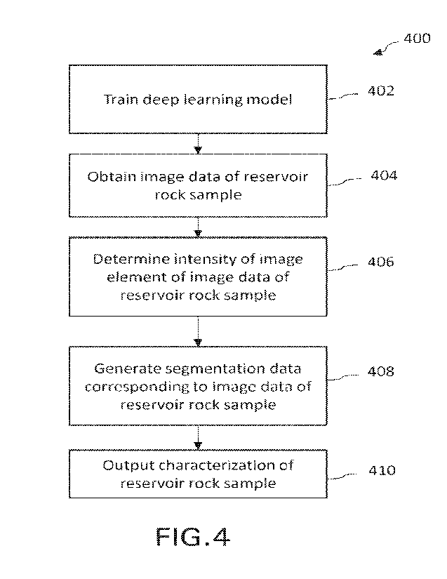
[0054] FIG. 4 is a flowchart of an illustrative process 400 for
automatic digital rock
segmentation using a deep learning model. For discussion purposes, process 400
will be
described with reference to FIG. 1 and the system 300 of FIG. 3. However,
process 400 is
not intended to be limited thereto.
Is [0055] In block 402, the process 400 involves training a deep
learning model (e.g., a
machine learning algorithm), such as deep learning model 312 of FIG. 3. As
described with
respect to FIG. 3, the deep learning model may be configured to output
multiple channels
(e.g., multiple classes). In this regard, the deep learning model may be a 3D
U-Net model.
Further, training the deep learning model may involve training the deep
learning model to
perform automatic digital rock segmentation. In particular, training the deep
learning model
may involve using training data (e.g., training data 326) to train the deep
learning model to
segment image data of a reservoir rock sample. In this regard, training the
deep learning
model may involve training the deep learning model to segment digital images
of reservoir
rock using image data of a set of reservoir rock samples (e.g., training image
data 330) and
segmentation data (e.g., training segmentation data 332) mapping an intensity
of each image
element in the image data to a particular output channel, where the output
channel represents
a characterization of the reservoir rock for a corresponding segment of the
image data.
Details of training the deep learning are provided in FIG. 5.
[0056] With reference now to FIG. 5, a flowchart of an
illustrative process for training a
deep learning model in accordance with block 402 of FIG. 4 is shown. For
discussion
purposes, FIG. 5 will be described with reference to FIG. .1, the system 300
of FIG. 3, and
FIG. 4. However, embodiments are not intended to be limited thereto.
18
CA 03206096 2023- 7- 21
WO 2022/216298
PCT/US2021/027997
[0057] In block 502, training image data and training
segmentation data are obtained.
As described with reference to FIG. 3, training image data and training
segmentation data
(e.g., collectively, "training data") may be retrieved from a memory or
storage device, such
as memory 310 or database 324. Moreover, the training image data may
correspond to image
data of reservoir rock samples obtained from a reservoir formation and
segmentation of such
image data. The reservoir rock samples and image data. of such samples may be
obtained in
accordance with embodiments described with respect to FIG. I. Further, the
training
segmentation data may correspond to segmentation data generated based on the
training
image data and in accordance with the segmentation described with respect to
FIGS. 2A-2B.
To that end, the segmentation data may be generated based on a user input. In
some
embodiments, the training segmentation data may correspond to segmentation
data
generated automatically by a deep learning model (e.g., generated without user
intervention),
such as deep learning model 312, as described in greater detail below. In any
case, the
segmentation data may identify (e.g., label) the different channels, such as
the pore channel,
Is the porous medium. channel, the mineral channel, and/or the like,
included within the image
data.
10058] In block 504, the training segmentation data is separated
into one or more binary
images. As indicated by the dashed lines, the block 504 is optionally
implemented and/or
included to train a deep learning model. For instance, if the training
segmentation data is
zo already separated into binary images, the block 504 may not be
performed. If, on the other
hand, the training data includes an image depicting multiple channels (e.g., a
multi-channel
image) and/or a grayscale or colored image, the block 504 may be performed.
Further, in
some embodiments, the deep learning model may be configured to generate an
output (e.g.,
channel outputs and/or segmentation data) as binary images. Accordingly,
separation of
25 segmentation data into binary images may enable the deep learning model
to more directly
map input image data to an output, as described in greater detail below. An
illustrative
example of a multi-channel is shown in at least FIGS. 2A-2B. Further,
performance of the
block 504 is described below with reference to FIGS. 6A-6C.
[0059] FIG. 6A illustrates an exemplary multi-channel image 600.
More specifically,
30 FIG. 6A illustrates a multi-channel image that includes segmentation
data identifying two
different channels. Further, the multi-channel image 600 represents an example
of training
data (e.g., training image data and training segmentation data). The
segmentation data is
illustrated by the differentiation between a first channel and a second
channel within the
19
CA 03206096 2023- 7- 21
WO 2022/216298
PCT/US2021/027997
multi-channel image 600. In particular, a mineral channel is indicated within
certain outlined
regions of the multi-channel image 600 via a striped fill pattern, while a
porous medium
channel is indicated as the remaining area of the multi-channel image 600.
Because multi-
channel image 600 illustrates segmentation data corresponding to multiple
different channels
s (e.g., the mineral channel and the porous medium channel), the multi-
channel image 600
may also be referred to as a composite image.
10060] According to the block 504 of FIG. 5, the multi-channel
image 600 may be split
into its component parts (e.g., component channels or layers). In some
embodiments, the
separation of a particular channel from a multi-channel image (e.g., multi-
channel image
to 600) into a binary image may be achieved by assigning image elements
(e.g., pixels and/or
voxels) segmented into the particular channel (e.g., indicated as
corresponding to the channel
in the segmentation data) a first value and assigning the remaining image
elements of the
image a different, second value. For instance, the segmentation data
corresponding to the
mineral channel may be extracted to a binary image from the multi-channel
image 600 by
Is assigning the image elements within the outlined, striped regions of the
multi-channel image
a first value. The mineral channel may further be extracted by assigning the
remaining image
elements (e.g., outside the outlined regions) a different, second value. An
example of such
a binary image is illustrated in FIG. 6B. More specifically, FIG 613
illustrates a binary image
620 in which white regions are identified as being associated with the mineral
channel and
zo the remaining, black regions are identified as not being associated with
the mineral channel
(e.g., as instead being associated with a different channel).
10061] The extraction and/or separation of binary images
described above may be
repeated for each channel included within a multi-channel image. With respect
to the multi-
channel image 600, for example, the extraction and/or separation may be
repeated to produce
25 a binary image corresponding to the porous medium channel. More
specifically, the
segmentation data corresponding to the porous medium channel may be extracted
to a binary
image from the multi-channel image 600 by assigning the image elements outside
the
outlined, striped regions of the multi-channel image 600 a first value. The
porous medium
channel may further be extracted by assigning the remaining image elements
(e.g., within
30 the outside the outlined, striped regions) a different, second value. An
example of such a
binary image is illustrated in FIG. 6C. More specifically, FIG 6C illustrates
a binary image
640 in which white regions are identified as being associated with the porous
medium
channel and the remaining black regions are identified as not being associated
with the
CA 03206096 2023- 7- 21
WO 2022/216298
PCT/US2021/027997
porous medium channel (e.g., as instead being associated with a different
channel). While a
particular method of generating binary images from segmentation data is
described herein,
embodiments are not limited thereto. In this regard, any suitable image
processing and/or
filtering techniques may be used to generate the binary images.
s [0062] Turning back now to FIG. 5, at block 506, the deep learning
model may be trained
using the training image data and the training segmentation data More
specifically, the deep
learning model may be trained to map an input, such as an input image and/or
image data
from the training image data, to an output, such as a set of binary images
(e.g., a set of output
channels), which may be included in the training segmentation data. For
instance, the deep
to learning model may be configured to identify correlations and/or
patterns between image
elements across a set of image data that are each mapped to a particular
output channel. In
some embodiments, for example, the deep learning model may, based on an
evaluation of
the training image data and the training segmentation data, determine that an
image element
with an intensity within a first range may correspond to the mineral channel,
while an image
Is element with an intensity within a second range may correspond to the pore
channel.
Additionally or alternatively, the deep learning model may determine that a
relative intensity
of an image element with respect to other image elements in an image may
correspond to a
particular channel. In this way, the deep learning model may account for
variations in
intensities of similar features (e.g., minerals, pores, porous medium, and/or
the like) between
zo different images, which may result from differences in equipment and/or
imaging modalities
used to obtain the images, for example. Further, because an expected output
(e.g.,
segmentation) for a given image of the training image data may be included in
the training
segmentation data, the training of the deep learning model may be supervised.
However,
embodiments are not limited thereto. In some embodiments, for example, a deep
learning
25 model may be trained to perform unsupervised segmentation.
[0063] At block 508, the deep learning model may optionally (as
indicated by the dashed
lines) be retrained. In some embodiments, for example, the training of the
deep learning
model may be validated using a set of validation data. The validation data may
be the same
as or different from the training data. In some embodiments, for example, the
validation data
30 may be a subset of the training data that was not previously used to
train the deep learning
model (e.g., at block 506). To validate the training of the deep learning
model, an input
image and/or image data of the validation data may be provided to the deep
learning model.
Subsequently, a segmentation of the image and/or image data provided by the
deep learning
21
CA 03206096 2023- 7- 21
WO 2022/216298
PCT/US2021/027997
model may be compared against a segmentation of image and/or image data
included in the
validation data. In some embodiments, if a similarity (e.g., a correlation)
between the
segmentation by the deep learning model and the segmentation of the validation
data satisfies
a threshold, the deep learning model may not be retrained at block 508. if, on
the other hand,
the similarity fails to satisfy the threshold, the deep learning model may be
retrained at block
508. Further, in some embodiments, the comparison of the segmentation of the
image data
by the deep learning model or of the validation data may be performed based on
an individual
channel or a set of output channels. To that end, a separate threshold may be
used for in a
respective comparison of different output channels or a single threshold may
be used for a
to comparison between a group of output channels. Moreover, the deep
learning model may
be retrained based on a particular output channel or may be retrained for a
set of output
channels. To this end, retraining the deep learning model that includes a
different deep
learning model for different output channels (e.g., a first deep learning
model for a first
output channel, a second deep learning model for a second output channel, and
so on) based
Is on a particular channel may involve retraining the deep leaning model
within the deep
learning model that is trained to segment (e.g., output) the particular
channel. Additionally
or alternatively, the deep learning model may be retrained based on a user
input, which may
be received via the GUI 314, as described above. For instance, the user input
may reject or
adjust a segmentation of an image provided by the deep learning model, and, in
response,
zo the deep learning model may be retrained so that a subsequent
segmentation of the image
aligns with the adjustment made by the user.
[0064] With reference now to FIG. 4, at block 404, the process
400 involves obtaining
image data of a reservoir rock sample, such as sample image data 334. In some
embodiments, the reservoir rock sample may be obtained from a reservoir
formation, such
25 as reservoir formation 113. To that end, the reservoir rock sample may
be a core sample
and/or a plug sample. Further, the image data may correspond to imaging data
output by an
imaging scan, such as imaging scan 117 of FIG. 1, of the sample. In this
regard, the image
data may include CT image data or image data corresponding to any suitable
imaging
modality. Moreover, the image data may include 213 images and/or 3:D image
data (e.g., a
30 sequence of 2D images), as well as color, grayscale, and/or binary
images. An example of
an image (e.g.., image data) of a reservoir rock sample is illustrated in FIG.
7A..
[0065] Further, as described with respect to FIG. 3, image data
of a reservoir rock sample
(e.g., sample image data 334) may be stored in memory, such as memory 310, or
a database,
22
CA 03206096 2023- 7- 21
WO 2022/216298
PCT/US2021/027997
such as database 324. In this regard, obtaining the image data may involve
receiving the
image data from an imaging device, such as a CT imaging device, or receiving
(e.g.,
retrieving) the image data from a data storage device (e.g., memory).
[0066] At block 406, the process 400 involves determining an
intensity of an image
element of the image data of the reservoir rock sample (e.g. an image element
of the sample
image data). More specifically, determining an intensity of an image element
may involve
determining a signal intensity associated with the image element and/or a
level of brightness
associated with the image element. In some embodiments, the image data may
include one
or more color, grayscale, binaty images, and/or the like. To that end, the
intensity of an
to image element of a color, grayscale, and/or binary image may be
determined. Determining
the intensity of an image element of a grayscale image may include determining
the
gayscale value and/or color of the image element. For instance, relatively
whiter image
elements may correspond to a greater intensity, while relatively blacker
elements may
correspond to a lower intensity, or vice versa. The intensity of the image
element may
IS additionally or alternatively be determined via image processing, such
as filtering of the
image data, conversion of the image data to grayscale, and/or the like.
10067] At block 408, the process 400 involves generating
segmentation data, such as
sample segmentation data 336) corresponding to the image data of the reservoir
rock sample.
The segmentation data may include one or more segmentations of the image data.
That is,
zo for example, the segmentation data may segment (e.g., label and/or
classify) different areas
of images within the image data based on a particular channel associated with
the areas. For
instance, the segmentation data may identify an area (e.g., an image element)
of an image as
corresponding to the pore channel, the porous medium channel, the mineral
channel, and/or
the like. In this regard, the segmentation data may map an intensity of image
elements of
25 the image data to a particular output channel, where the output channel
represents a
characterization of the reservoir rock sample for a corresponding segment of
the image data.
In some embodiments, the segmentation data may include a set of binary images,
where each
binary image corresponds to a respective output channel of the output channels
included in
the image data.
30 [0068] Further, the segmentation data may be generated using the deep
learning model
trained at block 402 (e.g., the trained deep learning model). In particular,
the trained deep
learning model may generate the segmentation data based on the intensity of
the image
element. For instance, based on the training of the deep learning model (e.g.,
at block 402),
23
CA 03206096 2023- 7- 21
WO 2022/216298
PCT/US2021/027997
the deep learning model may be configured to map the intensity of the image
element to a
particular output channel An indication of this output channel, such as a
binary image
corresponding to the output channel and associated with the image element, may
be included
in the segmentation data that is generated. In some embodiments, the
segmentation data may
be generated on a pixel-level and/or voxel-level (e.g., a volume element)
basis. For instance,
the intensity of each pixel and/or voxel included in the image data or the
reservoir rock
sample may be mapped to a respective output channel. The generation of
segmentation data
by a deep learning model is described in greater detail below with respect to
FIGS. 7A-7C.
[0069] FIG. 7A is exemplaty an image 700 (e.g., image data) or a
reservoir rock sample.
to In particular, FIG. 7A illustrates a multi-channel image. In some
embodiments, the image
700 may be input as image data or a portion thereof to a trained deep learning
model. In
some embodiments, the deep learning model may determine intensities of one or
more image
elements of the image 700. Additionally or alternatively the intensities of
the one or more
image elements may be input to the deep learning model Further, while the
image 700 is a
Is grayscale image. it may be appreciated that the techniques described
herein. (e.g., the
segmentation of image data) may be applied to color or any other suitable
images.
10070] Based on the input to the deep learning model, the deep
learning model may
provide a segmentation of the image 700. In particular, based on the
intensities of the one
or more image elements, the deep learning model may identify the image
elements as
zo corresponding to a particular output channel, such as a mineral output
channel, a porous
medium output channel, a pore channel, and/or the like. In some embodiments,
the deep
learning model may include a. single model trained to identify image elements
as
corresponding to any of a set of available output channels. Additionally or
alternatively, the
deep learning model may include different models (e.g., different deep
learning models) for
25 each available output channel. For instance, a first model may identify
image elements
corresponding to a first output channel (e.g., the mineral channel), a second
model may
identify image elements corresponding to a second output channel (e.g., the
porous medium
channel), a third model may identify image elements corresponding to a third
output channel
(e.g., the pore channel), and/or the like. Further the different models may
process the image
30 data (e.g., determine a segmentation) in sequence or in parallel with
one another.
[0071] Further, based on identifying an image element as
corresponding to a particular
output channel, the deep learning model may output segmentation data
corresponding to the
image element and the output channel. In particular, the deep learning model
may output a
24
CA 03206096 2023- 7- 21
WO 2022/216298
PCT/US2021/027997
binary image corresponding to the output channel and the image element. In
this regard,
FIGS. 7B-7C illustrate exemplary segmentation data generated by a trained deep
learning
model based on the image 700 of FIG 7A and in accordance with the process 400
of FIG.
4.
[0072] To output segmentation data, such as the binary images illustrated
in FIGS. 713-
7C, the deep learning model may assign a first value to an image element
corresponding to
an output channel and assign image elements of the image not corresponding to
the output
channel a different, second value, as similarly described above with reference
to FIGS. 6B-
6C. For instance, based on the multi-channel image 700, segmentation data
corresponding
m to the porous phase channel may be output as a binary image by assigning
image elements
identified as corresponding to the porous medium channel a first value. The
porous phase
channel may further be output by assigning the image elements identified as
not
corresponding to the porous medium channel a different, second value. An
example of such
a binary image is illustrated in FIG. 7B. More specifically, FIG. 713
illustrates a binary image
Is 720 in. which white regions (e.g., image elements) are identified as
being associated with the
porous medium channel and the remaining, black regions are identified as not
being
associated with the porous medium channel (e.g., as instead being associated
with a different
channel). Further, based on the multi-channel image 700, segmentation data
corresponding
to the mineral phase channel may be output as a binary image by assigning
image elements
zo identified as corresponding to the mineral phase channel a first value.
The mineral phase
channel may further be output by assigning the image elements identified as
not
corresponding to the mineral phase a different, second value. An example of
such a binary
image is illustrated in FIG. 7C. More specifically, FIG. 7C illustrates a
binary image 740 in
which white regions (e.g., image elements) are identified as being associated
with the
25 mineral channel and the remaining, black regions are identified as not
being associated with
the mineral medium channel (e.g., as instead being associated with a different
channel).
[0073] With reference now to FIG. 4, in some embodiments, the
segmentation data
generated at block 408 may be stored in association with the image data of the
reservoir rock
sample as training data (e.g., training data 326). The generated segmentation
data and image
30 data of the reservoir rock sample may then be subsequently used as
training data for training
or retraining the deep learning model. For instance, the image data of the
reservoir rock
sample may be used as an input to the deep learning model and may be mapped to
the output
of the generated segmentation data during training or retraining of the deep
learning model.
CA 03206096 2023- 7- 21
WO 2022/216298
PCT/US2021/027997
The generated segmentation data and image data of the reservoir rock sample
may
additionally or alternatively be used as training data for an additional deep
learning model.
For instance, the generated segmentation data and image data of the reservoir
rock sample
may be stored in a database, such as database 324, and may be accessed over a
network (e.g.,
network 322) by an in communication with the network. In this way, training of
the deep
learning model may be propagated to an additional deep learning model.
[0074] At block 410, the process 400 involves outputting a
characterization of the
reservoir rock sample. In some embodiments, the characterization may be based
on the
generated segmentation data. In this regard, outputting the characterization
may involve
to outputting the generated segmentation data. For instance, binary images
corresponding to
respective output channels, such as those illustrated in FIGS. 7A-7B, may be
output.
Additionally or alternatively, a composite image illustrating different output
channels within
an image may be output based on the generated segmentation data.
[0075] Further, in some embodiments, outputting the
characterization may involve
outputting an indication of a distribution of pores in the reservoir rock
sample, a size of the
pores in the reservoir rock sample, a model of the reservoir rock sample, a
simulation of the
model, and/or the like. The indication may be determined based on the
generated
segmentation data by data visualizer 318 and/or rock simulator 320, for
example.
[0076] In some embodiments, outputting the characterization may
involve outputting the
classification to a data storage device, such as a memory (e.g., memory 310)
and/or a
database (e.g., database 324). In some embodiments, outputting the
characterization may
involve outputting the characterization to a display, such as an electronic
display. The
characterization may be displayed within a GUI, such as GUI 315, for example.
Additionally
or alternatively, the characterization may be output to a processing system or
component,
such as data visualizer 318 and/or rock simulator 320. Moreover,
characterization of a
reservoir rock sample may correspond to a characterization of a reservoir
formation from
which the sample was obtained. To that end, the output of the characterization
may enable
reservoir simulations and well planning.
[0077] FIG. 8 is a block diagram of an illustrative computer
system 800 in which
embodiments of the present disclosure may be implemented. For example, the
functions,
components, and/or operations of processing system 119 or memory 121 of FIG.
1, system
300 of FIG. 3, process 400 of FIG. 4, and/or the process illustrated in FIG.
5, as described
above, may be implemented using system 800. System 800 can be a computer,
phone, PDA,
26
CA 03206096 2023- 7- 21
WO 2022/216298
PCT/US2021/027997
or any other type of electronic device. Such an electronic device includes
various types of
computer readable media and interfaces for various other types of computer
readable media.
As shown in FIG. 8, system 800 includes a permanent storage device 802, a
system memory
804, an output device interface 806, a system communications bus 808, a read-
only memory
(ROM) 810, processing unit(s) 812, an input device interface 814, and a
network interface
816.
10078] Bus 808 collectively represents all system, peripheral,
and chipset buses that
communicatively connect the numerous internal devices of system 800. For
instance, bus
808 communicatively connects processing unit(s) 812 with ROM 810, system
memory 804,
and permanent storage device 802.
10079] From these various memory units, processing unit(s) 812
retrieves instructions to
execute and data to process in order to execute the processes of the subject
disclosure. The
processing unit(s) can be a single processor or a multi-core processor in
different
implementations.
is [0080] :ROM 810 stores static data and instructions that are needed
by processing unit(s)
812 and other modules of system 800. Permanent storage device 802, on the
other hand, is
a read-and-write memory device. This device is a non-volatile memory unit that
stores
instructions and data even when system 800 is off Some implementations of the
subject
disclosure use a mass-storage device (such as a magnetic or optical disk and
its
zo corresponding disk drive) as permanent storage device 802.
10081] Other implementations use a removable storage device
(such as a floppy disk,
flash drive, and its corresponding disk drive) as permanent storage device
802. Like
permanent storage device 802, system memory 804 is a read-and-write memory
device.
However, unlike storage device 802, system memory 804 is a volatile read-and-
write
25 memory, such a random access memory. System memory 804 stores some of
the instructions
and data that the processor needs at runtime. In some implementations, the
processes of the
subject disclosure are stored in system memory 804, permanent storage device
802, and/or
ROM 810. For example, the various memory units include instructions for
implementing
the deep learning model, for training the deep learning model, and/or for
performing
30 automatic digital segmentation of a reservoir rock sample in accordance
with embodiments
of the present disclosure, e.g., according to the deep learning model 312 of
FIG. 3, process
400 of FIG. 4, and the process illustrated in FIG. 5, as described above. From
these various
27
CA 03206096 2023- 7- 21
WO 2022/216298
PCT/US2021/027997
memory units, processing unit(s) 812 retrieves instructions to execute and
data to process in
order to execute the processes of some implementations.
10082] Bus 808 also connects to input and output device
interfaces 814 and 806. Input
device interface 814 enables the user to communicate information and select
commands to
the system 800. Input devices used with input device interface 814 include,
for example,
alphanumeric, QWF,RTY, or T9 keyboards, microphones, and pointing devices
(also called
"cursor control devices"). Output device interfaces 706 enables, for example,
the display of
images generated by the system 800. Output devices used with output device
interface 806
include, for example, printers and display devices, such as cathode ray tubes
(CRT) or liquid
to crystal displays (LCD). Some implementations include devices such as a
touchscreen that
functions as both input and output devices. It should be appreciated that
embodiments of the
present disclosure may be implemented using a computer including any of
various types of
input and output devices for enabling interaction with a user. Such
interaction may include
feedback to or from the user in different forms of sensory feedback including,
but not limited
Is to, visual feedback, auditory feedback, or tactile feedback. Further,
input from the user can
be received in any form including, but not limited to, acoustic, speech, or
tactile input.
Additionally, interaction with the user may include transmitting and receiving
different types
of information, e.g., in the form of documents, to and from the user via the
above-described
interfaces.
zo 10083] Also, as shown in FIG. 8, bus 808 also couples system 800 to a
public or private
network (not shown) or combination of networks through a network interface
816. Such a
network may include, for example, a local area network ("LAN"), such as an
Intranet, or a
wide area network ("WAN"), such as the Internet. Any or all components of
system 800 can
be used in conjunction with the subject disclosure.
25 10084] These functions described above can be implemented in digital
electronic
circuitry, in computer software, firmware or hardware. The techniques can be
implemented
using one or more computer program products. Programmable processors and
computers
can be included in or packaged as mobile devices. The processes and logic
flows can be
performed by one or more programmable processors and by one or more
programmable logic
30 circuitry. General and special purpose computing devices and storage
devices can be
interconnected through communication networks.
[0085] Some implementations include electronic components, such
as microprocessors,
storage and memory that store computer program instructions in a machine-
readable or
28
CA 03206096 2023- 7- 21
WO 2022/216298
PCT/US2021/027997
computer-readable medium (alternatively referred to as computer-readable
storage media,
machine-readable media, or machine-readable storage media). Some examples of
such
computer-readable media include :RAM, ROM, read-only compact discs (CD-ROM),
recordable compact discs (C.D-R), rewritable compact discs (C.D-RW), read-only
digital
versatile discs (e.g., DVD-ROM, dual-layer DVD-ROM), a variety of
recordable/rewritable
D'VDs (e.g., DVD-R AM, DVD-RW, 'ffNeT)-+RW, etc.), flash memory (e.g., SD
cards, mini-
SD cards, micro-SD cards, etc.), magnetic and/or solid state hard drives, read-
only and
recordable Blu-Ray discs, ultra density optical discs, any other optical or
magnetic media,
and floppy disks. The computer-readable media can store a computer program
that is
to executable by at least one processing unit and includes sets of
instructions for performing
various operations. Examples of computer programs or computer code include
machine
code, such as is produced by a compiler, and files including higher-level code
that are
executed by a computer, an electronic component, or a microprocessor using an
interpreter.
[0086] While the above discussion primarily refers to
microprocessor or multi-core
Is processors that execute software, some implementations are performed by one
or more
integrated circuits, such as application specific integrated circuits (ASICs)
or field
programmable gate arrays (FPGAs). In some implementations, such integrated
circuits
execute instructions that are stored on the circuit itself. Accordingly,
process 400 of FIG. 4,
as described above, may be implemented using system 800 or any computer system
having
zo processing circuitry or a computer program product including
instructions stored therein,
which, when executed by at least one processor, causes the processor to
perform functions
relating to these methods.
[0087] As used in this specification and any claims of this
application, the terms
"computer", "server", "processor", and "memory" all refer to electronic or
other
25 technological devices. These terms exclude people or groups of people.
As used herein, the
terms "computer readable medium" and "computer readable media" refer generally
to
tangible, physical, and non-transitory electronic storage mediums that store
information in a
form that is readable by a computer.
[0088] Embodiments of the subject matter described in this
specification can be
30 implemented in a computing system that includes a back end component,
e.g., as a data
server, or that includes a iniddleware component, e.g., an application server,
or that includes
a front end component, e.g., a client computer having a graphical user
interface or a Web
browser through which a user can interact with an implementation of the
subject matter
29
CA 03206096 2023- 7- 21
WO 2022/216298
PCT/US2021/027997
described in this specification, or any combination of one or more such back
end,
middleware, or front end components. The components of the system can be
interconnected
by any form or medium of digital data communication, e.g., a communication
network.
Examples of communication networks include a local area network ("LAN") and a
wide area
network ("WAN"), an inter-network (e.g., the Internet), and peer-to-peer
networks (e.g., ad
hoc peer-to-peer networks)
[0089] The computing system can include clients and servers. A
client and server are
generally remote from each other and typically interact through a
communication network.
The relafionship of client and server arises by virtue of computer programs
running on the
to respective computers and having a client-server relationship to each
other. In some
embodiments, a server transmits data (e.g., a web page) to a client device
(e.g., for purposes
of displaying data to and receiving user input from a user interacting with
the client device).
Data generated at the client device (e.g., a result of the user interaction)
can be received from
the client device at the server.
is [0090] It is understood that any specific order or hierarchy of steps
in the processes
disclosed is an illustration of exemplary approaches. Based upon design
preferences, it is
understood that the specific order or hierarchy of steps in the processes may
be rearranged,
or that all illustrated steps be performed. Some of the steps may be performed
simultaneously. For example, in certain circumstances, multitasking and
parallel processing
zo may be advantageous. Moreover, the separation of various system components
in the
embodiments described above should not be understood as requiring such
separation in all
embodiments, and it should be understood that the described program components
and
systems can generally be integrated together in a single software product or
packaged into
multiple software products.
25 [0091] Furthermore, the exemplary methodologies described herein may be
implemented by a system including processing circuitry or a computer program
product
including instructions which, when executed by at least one processor, causes
the processor
to perform any of the methodology described herein.
[0092] As described above, embodiments of the present disclosure
are particularly useful
30 for automatically and digitally characterizing reservoir rock samples.
In one embodiment of
the present disclosure, a computer-implemented method for characterizing
reservoir rock
includes: training a deep learning model to segment digital images of
reservoir rock using
first image data of a set of reservoir rock samples and first segmentation
data mapping an
CA 03206096 2023- 7- 21
WO 2022/216298
PCT/US2021/027997
intensity of each image element of the first image data to one of a plurality
of output
channels, each of the plurality of output channels representing a different
characterization of
the reservoir rock for a corresponding segment of the first image data;
obtaining second
image data of a new reservoir rock sample; determining an intensity of each
image element
of the second image data; generating, using the trained deep learning model,
second
segmentation data mapping the intensity of each image element in the second
image data to
a corresponding one of the plurality of output channels of the trained deep
learning model;
and utilizing the trained deep learning model to output a characterization of
the new reservoir
rock sample, based on the second segmentation data generated for the second
image data.
100931 In one or more embodiments of the foregoing computer-implemented
method:
the plurality of output channels includes at least one of a mineral channel, a
pore channel,
and a porous medium channel; the first segmentation data includes a plurality
of binary
images, where each of the plurality of binary images corresponds to a
respective one of the
plurality of output channels; the method includes generating the first
segmentation data,
Is where the generating the first segmentation data includes
separating a multi-channel image
into the plurality of binary images based on a segmentation of the multi-
channel image; the
second image data includes three-dimensional (3D) image data of the new
reservoir rock
sample; the 3D image data includes a sequence of two-dimensional (2D) images;
each image
element is a voxel representing a corresponding volume of the reservoir rock
in the
respective first and second image data; the generating the second segmentation
data includes:
generating, using the trained deep learning model, a binary image
corresponding to at least
one image element of the second image data and the corresponding one of the
plurality of
output channels; the deep learning model includes a three-dimensional U-Net
model; the
method further involves outputting the second segmentation data to a data
storage device;
and the characterization of the new reservoir rock sample includes an
indication of a
distribution of pores in the new reservoir rock sample, a size of the pores in
the new reservoir
rock sample, or a model of the new reservoir rock sample.
[0094] In one embodiment of the present disclosure, a system is
disclosed, where the
system includes: a processor; and a memory having processor-readable
instructions stored
therein, which, when executed by the processor, cause the processor to perform
a plurality
of functions, including functions to: train a deep learning model to segment
digital images
of reservoir rock using first image data of a set of reservoir rock samples
and first
segmentation data mapping an intensity of each image element of the first
image data to one
31
CA 03206096 2023- 7- 21
WO 2022/216298
PCT/US2021/027997
of a plurality of output channels, each of the plurality of output channels
representing a
different characterization of the reservoir rock for a corresponding segment
of the first image
data; obtain second image data of a new reservoir rock sample; determine an
intensity of
each image element of the second image data; generate, using the trained deep
learning
model, second segmentation data mapping the intensity of each image element in
the second
image data to a corresponding one of the plurality of output channels of the
trained deep
learning model; and utilize the trained deep learning model to output a
characterization of
the new reservoir rock sample, based on the second segmentation data generated
for the
second image data.
[0095] In one or more embodiments of the foregoing system: the plurality of
output
channels includes at least one of a mineral channel, a pore channel, and a
porous medium
channel; the first segmentation data includes a plurality of binary images,
where each of the
plurality of binary images corresponds to a respective one of the plurality of
output channels;
the plurality of functions further includes functions to: generate the first
segmentation data,
Is where the generating the first segmentation data includes separating a
multi-channel image
into the plurality of binary images based on a segmentation of the multi-
channel image; the
second segmentation data includes a binary image corresponding to at least one
image
element of the second image data and the corresponding one of the plurality of
output
channels; the deep learning model includes a three-dimensional U-Net model;
the plurality
of functions further includes functions to: output the second segmentation
data to a data
storage device; where the characterization of the new reservoir rock sample
includes an
indication of a distribution of pores in the new reservoir rock sample, a size
of the pores in
the new reservoir rock sample, or a model of the new reservoir rock sample.
[0096] In another embodiment of the present disclosure, a
computer-readable storage
medium having computer-readable instructions stored therein, which, when
executed by a
computer, cause the computer to perform a plurality of functions, including
functions to:
train a deep learning model to segment digital images of reservoir rock using
first image data
of a set of reservoir rock samples and first segmentation data mapping an
intensity of each
image element of the first image data to one of a plurality of output
channels, each of the
plurality of output channels representing a different characterization of the
reservoir rock for
a corresponding segment of the first image data; obtain second image data of a
new reservoir
rock sample; determine an intensity of each image element of the second image
data;
generate, using the trained deep learning model, second segmentation data
mapping the
32
CA 03206096 2023- 7- 21
WO 2022/216298
PCT/US2021/027997
intensity of each image element in the second image data to a corresponding
one of the
plurality of output channels of the trained deep learning model; and utilize
the trained deep
learning model to output a characterization of the new reservoir rock sample,
based on the
second segmentation data generated for the second image data.
[0097] While specific details about the above embodiments have been
described, the
above hardware and software descriptions are intended merely as example
embodiments and
are not intended to limit the structure or implementation of the disclosed
embodiments. For
instance, although many other internal components of the system 800 are not
shown, those
of ordinary skill in the art will appreciate that such components and their
interconnection are
to well known.
[0098] In addition, certain aspects of the disclosed
embodiments, as outlined above, may
be embodied in software that is executed using one or more processing
units/components.
Program aspects of the technology may be thought of as "products" or "articles
of
manufacture" typically in the form of executable code and/or associated data
that is carried
Is on or embodied in a type of machine readable medium. Tangible non-
transitory "storage"
type media include any or all of the memory or other storage for the
computers, processors
or the like, or associated modules thereof, such as various semiconductor
memories, tape
drives, disk drives, optical or magnetic disks, and the like, which may
provide storage at any
time for the software programming.
20 10099] Additionally, the flowchart and block diagrams in the figures
illustrate the
architecture, functionality, and operation of possible implementations of
systems, methods
and computer program products according to various embodiments of the present
disclosure. It should also be noted that, in some alternative implementations,
the functions
noted in the block may occur out of the order noted in the figures. For
example, two blocks
25 shown in succession may, in fact, be executed substantially
concurrently, or the blocks may
sometimes be executed in the reverse order, depending upon the functionality
involved. It
will also be noted that each block of the block diagrams and/or flowchart
illustration, and
combinations of blocks in the block diagrams and/or flowchart illustration,
can be
implemented by special purpose hardware-based systems that perform the
specified
30 functions or acts, or combinations of special purpose hardware and
computer instructions.
[00100] The above specific example embodiments are not intended to limit the
scope of
the claims. The example embodiments may be modified by including, excluding,
or
combining one or more features or functions described in the disclosure.
33
CA 03206096 2023- 7- 21
WO 2022/216298
PCT/US2021/027997
[001011 As used herein, the singulnr forms "a", "an" and "the" are intended to
include the
plural forms as well, unless the context clearly indicates otherwise. It will
be further
understood that the terms "comprise" and/or "comprising," when used in this
specification
and/or the claims, specify the presence of stated features, integers, steps,
operations,
elements, and/or components, but do not preclude the presence or addition of
one or more
other features, integers, steps, operations, elements, components, and/or
groups thereof. The
corresponding structures, materials, acts, and equivalents of all means or
step plus function
elements in the claims below are intended to include any structure, material,
or act for
performing the function in combination with other claimed elements as
specifically claimed.
to The description of the present disclosure has been presented for
purposes of illustration and
description but is not intended to be exhaustive or limited to the embodiments
in the form
disclosed. Many modifications and variations will be apparent to those of
ordinary skill in
the art without departing from the scope and spirit of the disclosure. The
illustrative
embodiments described herein are provided to explain the principles of the
disclosure and
the practical application thereof, and to enable others of ordinary skill in
the art to understand
that the disclosed embodiments may be modified as desired for a particular
implementation
or use. The scope of the claims is intended to broadly cover the disclosed
embodiments and
any such modification.
34
CA 03206096 2023- 7- 21