Note: Descriptions are shown in the official language in which they were submitted.
zG10004
ASSEMBLY STRUCTURE FOR TENT AND VARIOUSLY
EXPANDABLE OUTDOOR TENT
FIELD OF TECHNOLOGY
The present invention relates to the field of outdoor product technologies,
and in particular
to an assembly structure for a tent and a variously expandable outdoor tent.
BACKGROUND
Outdoor tents are sheds that are supported on the ground to perform shielding
from wind,
rain and sunlight and are used for temporary living. The outdoor tent
generally includes a
canopy structure and a tent frame structure. The tent frame is usually formed
by four stand
columns and the ring beams connecting the four stand columns. Due to the
different
specifications of the tents, the ring beam may be formed by spliced ring beams
or a single
ring beam. For the packaging and transportation of the tent, especially, the
tent frame is
usually designed to be assemblable.
Therefore, the connection structure configured to connect the ring beams,
stand columns,
and other components is particularly important. However, the existing
connection structure
is complicated to assemble and the connection structure limits the existing
mounted
structure. As a result, the entire tent frame cannot be variously expanded,
with great
limitations.
SUMMARY
To resolve the foregoing problem, the present invention provides an assembly
structure for
a tent and a variously expandable outdoor tent. The stand columns and the ring
beam
1
CA 03206242 2023- 7- 24
ZG10004
structures are optimized. By using the assembly slots, different components
can be
combined and mounted variously, improving the performance of the product and
enriching
the diversification of the product.
The technical problem of the present invention can be resolved by using the
following
technical solution:
An assembly structure for a tent includes stand columns and ring beams, where
the stand
column and the ring beam are each provided with an assembly slot, the stand
columns and
the ring beams can be assembled by using first connection components to form a
tent frame,
the first connection component includes a connection component unit 1
configured to be
cooperatively mounted with the assembly slot in the stand column, a connection
component
unit 2 configured to be cooperatively mounted with the assembly slot in the
ring beam, and
a connection component unit 3 configured to dock the connection component unit
1 and
the connection component unit 2.
The assembly slot includes a slot cavity and an open slot penetrating through
the slot cavity,
limiting plates are disposed at two sides of the open slot, and a part of the
slot cavity
adjacent to the open slot is wider than the open slot.
The first connection component includes a plurality of fastening insert
members and
assembly members, the fastening insert member is configured to match with the
assembly
slot, the fastening insert member includes a fastening insert part and a
fixing part, the
fastening insert part is configured to match with the slot cavity, the fixing
part is configured
to match with the open slot, an outer surface of the fixing part is provided
with a fixed hole,
the fastening insert member in the connection component unit 1 is configured
to match
with the assembly slot in the stand column, the fastening insert member in the
connection
2
CA 03206242 2023- 7- 24
ZG10004
component unit 2 is configured to match with the assembly slot in the ring
beam, and the
connection component unit 3 is configured to perform cooperative mounting with
the
fastening insert members.
The assembly member includes a ring-beam inner liner, a first anchor member,
and a
second anchor member, the ring-beam inner liner is embedded and mounted at one
end of
the ring beam, the first anchor member is embedded and mounted in the ring-
beam inner
liner, an anchor head protrudes from an end face of the ring-beam inner liner,
the anchor
head is configured to be cooperatively embedded with the assembly slot, an
inner limit hole
is provided on the ring-beam inner liner, an outer limit hole corresponding to
the inner limit
hole is disposed on the ring beam, and the second anchor member is configured
to penetrate
through the outer limit hole and the inner limit hole, to match with the first
anchor member.
The connection component unit 3 includes an angle-iron member, an upper end
face and a
side end face of the angle-iron member match with fixing parts respectively,
and the fixing
parts are a fixing part on a fastening insert member configured to be
cooperatively mounted
with the ring beam and a fixing part on a fastening insert member configured
to be
cooperatively mounted with the stand column, respectively.
The connection component unit 3 includes a reinforcing rod, two ends of the
reinforcing
rod are configured to be cooperatively mounted with fixing parts respectively,
and the
fixing parts located at the two ends are, respectively, fixing parts on
fastening insert
members correspondingly mounted on upper surfaces of two adjacent ring beams
in
cooperation at two sides of the stand column.
3
CA 03206242 2023- 7- 24
ZG10004
A top of the stand column is cooperatively provided with a stand column inner
liner, the
stand column inner liner is configured to be embedded in a stand column inner
cavity, and
an upper surface of the stand column inner liner is provided with an end cover
plate.
The ring beam located between two adjacent stand columns is formed by docking
two ring
beam units, the ring beam units are cooperatively mounted by using a second
connection
component, the second connection component includes a docking fastening insert
member,
a reinforcing plate, and a docking ring-beam inner liner, the docking
fastening insert
member includes a docking fastening insert part and a docking fixing part, the
docking
fastening insert part is configured to match with the slot cavity, the docking
fixing part is
configured to match with the open slot, an outer surface of the docking fixing
part is
provided with a docking fixing hole, the docking fixing hole is configured to
match with
the reinforcing plate, a fastener is configured to realize reinforcing and
fixing, the docking
ring-beam inner liner is divided into two symmetrical parts, and the two parts
are embedded
in inner cavities of two docked ring beam units respectively.
The docking fastening insert member is configured to be cooperatively mounted
with
adjacent docked ring beams, and the docking fastening insert member is
symmetrically
mounted in assembly slots of two adjacent docked ring beams.
A variously expandable outdoor tent based on an assembly structure for a tent
includes the
tent frame described above, and a canopy configured to be cooperatively
mounted with the
tent frame.
The tent frame includes at least one tent frame unit, and a single canopy is
cooperatively
disposed in a single tent frame unit.
4
CA 03206242 2023- 7- 24
ZG10004
The canopy includes one or more of a tarpaulin canopy, a louver canopy, a tin
canopy, a
sun panel canopy, an umbrella canopy, and an inclined canopy.
Two or more tent frame units are provided, and ring beams, at a same side, of
two adjacent
tent frame units are cooperatively mounted by using a same stand column.
The variously expandable outdoor tent based on an assembly structure for a
tent further
includes at least one expansion unit, where the expansion unit is
cooperatively mounted
with an assembly slot by using a third connection component.
The third connection component includes a clamping member, and the expansion
unit is
cooperatively fixed to a fixing part on the clamping member by using a
fastener.
The expansion unit includes a sunshade shutter, the expansion unit is
cooperatively
mounted with an assembly slot below the ring beam by using the third
connection
component, and the expansion unit is hanged below the ring beam.
The expansion unit includes a sun-shedding louver, the sun-shedding louver is
cooperatively mounted with the assembly slot below the ring beam by using the
third
connection component, and the sun-shedding louver is hanged below the ring
beam.
The expansion unit includes a grille assembly, and the grille assembly is
cooperatively
mounted with an assembly slot on a stand column by using the third connection
component.
A table board is cooperatively disposed on an upper part of the grille
assembly, and at least
one side of the table board is cooperatively mounted with the assembly slot on
the stand
column by using the third connection component.
CA 03206242 2023- 7- 24
ZG10004
The expansion unit includes a stool chair, and the stool chair is
cooperatively mounted with
the assembly slot on the stand column by using the third connection component.
The expansion unit includes a decorative panel, and the decorative panel is
integrally or
separately fixed to the third connection component and is cooperatively
mounted with the
assembly slot of the stand column.
Compared with the related art, the present invention has the following
beneficial effects,
the assembly slot structures are optimally designed, and are combined on the
stand columns
and the ring beams. In addition, by using different connection components and
cooperation
relationships with the assembly slots, the stand columns and the ring beams
can be
combined and mounted quickly, the ring beam components can also be docked and
mounted, and different expansion units can be combined and mounted, to
assemble tents
with different functions.
The features of the present invention can be clearly understood from the
description of the
drawings and the detailed description of the preferable embodiments.
BRIEF DESCRIPTION OF THE DRAWINGS
FIG. 1 is a schematic diagram 1 of an entire structure of an outdoor tent
according to the
present invention.
FIG. 2 is a schematic diagram of a stand column structure according to the
present
invention.
FIG. 3 is a schematic sectional view of an assembly slot according to the
present invention.
6
CA 03206242 2023- 7- 24
ZG10004
FIG. 4 is a schematic structural diagram 1 of a mounted structure of a stand
column and
ring beams according to the present invention.
FIG. 5 is a schematic structural diagram 2 of the mounted structure of the
stand column
and ring beams according to the present invention.
FIG. 6 is a schematic structural diagram of a first connection component
according to the
present invention.
FIG. 7 is a schematic structural diagram of a fastening insert member
according to the
present invention.
FIG. 8 is a schematic structural diagram 1 of a mounted structure of the ring
beam and an
assembly member according to the present invention.
FIG. 9 is a schematic structural diagram 2 of the mounted structure of the
ring beam and
the assembly member according to the present invention.
FIG. 10 is a schematic structural diagram 3 of the mounted structure of the
stand column
and the ring beams according to the present invention.
FIG. 11 is a schematic structural diagram of a cooperatively mounted structure
of a first
anchor member and a second anchor member according to the present invention.
FIG. 12 is a schematic structural diagram 4 of the mounted structure of the
stand column
and the ring beams according to the present invention.
FIG. 13 is a schematic structural diagram 5 of the mounted structure of the
stand column
and the ring beams according to the present invention.
7
CA 03206242 2023- 7- 24
ZG10004
FIG. 14 is a schematic structural diagram 1 of a mounted structure of the ring
beams
according to the present invention.
FIG. 15 is a schematic structural diagram of a docking fastening insert member
according
to the present invention.
FIG. 16 is a schematic structural diagram 2 of the mounted structure of the
ring beams
according to the present invention.
FIG. 17 is a schematic diagram 2 of the entire structure of the outdoor tent
according to the
present invention.
FIG. 18 is a schematic diagram 3 of the entire structure of the outdoor tent
according to the
present invention.
FIG. 19 is a schematic diagram 4 of the entire structure of the outdoor tent
according to the
present invention.
FIG. 20 is a schematic diagram 5 of the entire structure of the outdoor tent
according to the
present invention.
FIG. 21 is a schematic diagram 6 of the entire structure of the outdoor tent
according to the
present invention.
FIG. 22 is a schematic diagram 7 of the entire structure of the outdoor tent
according to the
present invention.
FIG. 23 is a schematic diagram 8 of the entire structure of the outdoor tent
according to the
present invention.
8
CA 03206242 2023- 7- 24
ZG10004
FIG. 24 is a schematic diagram 9 of the entire structure of the outdoor tent
according to the
present invention.
FIG. 25 is a schematic diagram 10 of the entire structure of the outdoor tent
according to
the present invention.
FIG. 26 is a schematic diagram 11 of an entire structure of the outdoor tent
according to
the present invention.
FIG. 27 is a schematic diagram 12 of the entire structure of the outdoor tent
according to
the present invention.
FIG. 28 is a schematic diagram 13 of the entire structure of the outdoor tent
according to
the present invention.
FIG. 29 is a schematic diagram 14 of the entire structure of the outdoor tent
according to
the present invention.
FIG. 30 is a schematic diagram 15 of the entire structure of the outdoor tent
according to
the present invention.
FIG. 31 is a schematic structural diagram 1 of a matched structure of an
expansion unit and
a third connection component according to the present invention.
FIG. 32 is a schematic structural diagram 2 of the matched structure of an
expansion unit
and a third connection component according to the present invention.
DESCRIPTION OF THE EMBODIMENTS
9
CA 03206242 2023- 7- 24
ZG10004
In order to make the technical means, creative features, achievement goals and
effects
achieved by the present invention easy to understand, the present invention is
further
described below in conjunction with specific illustrations.
It should be noted that all the directional indications (for example, up,
down, left, right,
front, and back) in the embodiments of the present invention are only used to
explain the
relative positional relationship, motion situation, and the like between the
components at a
specific angle (as shown in the drawings). If the specific angle changes, the
directional
indications also change accordingly. In addition, the descriptions of "first",
"second" and
the like in the present invention are used for the purpose of description
only, and are not to
be construed as indicating or implying their relative importance or implicitly
indicating the
number of technical features indicated. Thus, a feature defined by "first" or
"second" may
explicitly or implicitly includes at least one of the features.
Embodiment 1
With reference to FIGS. 1 to 32, this embodiment discloses an assembly
structure for a tent,
including stand columns 1 and ring beams 2. In some embodiments, the stand
column 1 or
the ring beam 2 is correspondingly provided with an assembly slot 4 for the
mounting
purpose. In a preferable embodiment, the stand column 1 and the ring beam 2
are each
provided with the assembly slot 4. The stand column 1 and the ring beam 2 can
be
assembled by using a first connection component 5 to form a tent frame 7. The
first
connection component 5 includes a connection component unit 1 configured to be
cooperatively mounted with the assembly slot 4 in the stand column 1, a
connection
component unit 2 configured to be cooperatively mounted with the assembly slot
4 in the
ring beam 2, and a connection component unit 3 configured to dock the
connection
component unit 1 and the connection component unit 2. Preferably, the tent
frame 7
CA 03206242 2023- 7- 24
ZG10004
includes four stand columns 1 and ring beams 4 mounted between upper parts of
adjacent
stand columns 1. In the other embodiments, the tent frame 7 may include more
stand
columns 1 and the ring beams 2 correspondingly.
As shown in FIG. 3, the assembly slot 4 includes a slot cavity 41 and an open
slot 42
penetrating through the slot cavity 41. Limiting plates 43 are disposed at two
sides of the
open slot 42 respectively. The limiting plate 43 is configured to prevent the
disengagement
of a fastening insert member 51. A part of the slot cavity 41 adjacent to the
open slot 42 is
wider than the open slot 42. In a specific structure, the slot cavity 41 is
preferably of a
dovetail groove structure. The cross-sectional shape of the slot cavity 41 is
similar to an
isosceles trapezoid. Corners are set with arc transitions. The long side of
the slot cavity 41
is adjacent to the open slot. The limiting plate 43 extends. The assembly slot
4 is disposed
on the stand column 1 or the ring beam 2 along the length direction, and the
head and the
tail communicate.
The assembly slots 4 in different components are marked with different serial
numbers in
the accompanying drawings, such as the assembly slot 4a in the stand column 1
and the
assembly slot 4b in the ring beam 2. Because the formed structures or matching
components are different to some extent, the assembly slots 4 are in a same
slot shape, but
can have different specific sizes, especially, the lengths, which can be
correspondingly
selected according to different components. In some embodiments, the assembly
slots 4
may have a same size. In some other embodiments, the assembly slots 4 may have
different
sizes. In addition, because the assembly slots 4b are in different surfaces of
the ring beam
2 and need to be correspondingly mounted with different components, the sizes
of these
assembly slots 4 may be adjusted separately according to the requirements.
11
CA 03206242 2023- 7- 24
ZG10004
In a preferable solution, with reference to FIG. 2, the assembly slots 4a are
disposed at
centers of four sides of the stand column 1, such that in a subsequent process
of assembling
the stand column 1, a plurality of sides of the stand column can be extended
in a plurality
of directions as required.
In a preferable solution, according to a use requirement, corresponding
assembly slots 4b
may be disposed on the ring beam 2. Especially, to reinforce and fix the ring
beam 2, two
parallel assembly slots 4b are generally provided on at least one side surface
of the ring
beam 2, such that the ring beams are docked by using the docking fastening
insert member
61. By using such a double-slot structure, the stability can be reinforced. In
addition, the
assembly slots 4b are further disposed on an upper surface and a lower surface
of the ring
beam 2 respectively, and are configured to help the connection and mounting of
the
expansion unit 8 or the other reinforcing components, while facilitating
cooperatively
mounting the component in the canopy 3 with the ring beam 2.
In the present invention, the assembly slot 4 structures are optimally
designed, and are
combined on the stand columns 1 and the ring beams 2. In addition, by using
different
connection components and cooperation relationships with the assembly slots 4,
the stand
columns 1 and the ring beams 2 can be combined and mounted quickly, the
components of
the ring beams 2 can also be docked and mounted, and different expansion units
8 can be
combined and mounted, to assemble tents with different functions.
Embodiment 2
Based on Embodiment 1, with reference to FIGS. 4 to 16, this embodiment
discloses a
mounted structure of the stand columns and the ring beams in the tent frame.
The structure
includes a first connection component 5, The first connection component 5 is
configured
12
CA 03206242 2023- 7- 24
ZG10004
to fix and mount the stand column 1 and the ring beam 2. The first connection
component
includes a plurality of fastening insert members 51 and assembly members.
Because the
assembly member has a different function and a plurality of assembly
components, the
assembly member may include a single component. The quantity of the assembly
components may be set according to a different mounting requirement. The
fastening insert
member 51 includes a fastening insert part 511 and a fixing part 512. The
fastening insert
part 511 is configured to match with the slot cavity 41. The fixing part 512
is configured to
match with the open slot 42. An outer surface of the fixing part 511 is
provided with a fixed
hole 513. The fixed hole 513 is a through hole.
A plurality of fastening insert members 51 are provided as general components.
In a
specific mounting process, according to the mounting position and a
corresponding
requirement of a to-be-mounted assembly member, the length of the fastening
insert
member 51 may be adjusted and selected. The fastening insert member 51 may be
drawn
into a specified position along the slot cavity 41 from the opening position
of the end face
of the stand column 1 or the ring beam 2. Docking is implemented by using
assembly
members with different functions, such that quick assembling and mounting can
be
implemented by using the assembly slots 4 and the other components through the
fastening
insert members 51. In this case, according to a requirement of the mounting
position, an
alignment hole is provided on the short side of the slot cavity 41 of the
assembly slot 4, to
locate and fix the position. After the fastening insert part in the fastening
insert member 51
matches with the slot cavity 42, it cannot be disengaged from the open slot
42. The fixing
part 512 matched with the open slot 42 is beneficial the matching for other
components.
Preferably, the fixing part 512 partially protrudes from the open slot 42, and
extends outside,
or the outer surface of the fixing part 512 and the outer surface of the open
slot 42 are at a
same level. In a specific mounted structure, the fixed hole 513 is generally a
through hole,
13
CA 03206242 2023- 7- 24
ZG10004
and therefore is conveniently aligned with the alignment hole in the assembly
slot 4, such
that the tent structure is mounted and fixed by using screws or bolts.
Generally, two or more
fixed holes 513 are provided.
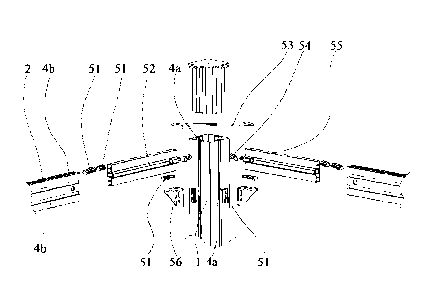
A specific mounted structure of the stand columns 1 and the ring beams 2
further includes
an assembly member, which may include a plurality of components according to
different
mounting positions and requirements. Specifically, the assembly member
includes a ring-
beam inner liner 52, a first anchor member 54, and a second anchor member 55.
The ring-
beam inner liner 52 is embedded at one end of the ring beam 2, until an end
face of the
ring-beam inner liner 52 and the end face of the ring beam 2 are at the same
level. The first
anchor member 54 is embedded in the ring-beam inner liner 52. In addition, an
anchor head
541 protrudes from the end face of the ring-beam inner liner 52. An anchor
embedding slot
cavity configured to match with the first anchor member 54 is disposed in the
ring-beam
inner liner 52. In addition, an inner limit hole 521 is disposed in the ring-
beam inner liner
52. The inner limit hole 521 communicates with the anchor embedding slot
cavity. An outer
limit hole 21 corresponding to the inner limit hole 521 is disposed on the
ring beam 2. In a
mounted structure, an assembly docking hole is disposed on the second anchor
member 55.
The second anchor member 55 penetrates through the outer limit hole 21 and the
inner limit
hole 521. After the first anchor member 54 is embedded, it penetrates through
the assembly
docking hole on the second anchor member 55, to implement the whole mounting
and
fixing. In another mounted structure, the alignment hole in the first anchor
member 54
matches with the inner limit hole 521 correspondingly. In this case, a docking
hole is
disposed on a part of the first anchor member 54 embedded in the ring-beam
inner liner 52.
After the first anchor member 54 is embedded, the outer limit hole 21, the
inner limit hole
521, and the docking hole communicate. By enabling the second anchor members
55 to
penetrate the outer limit holes 21, the inner limit holes 521, and the docking
holes, various
14
CA 03206242 2023- 7- 24
ZG10004
components are docked and mounted, and the assembly members and the ring beams
2 are
cooperatively mounted. In this case, the anchor head 541 of the first anchor
member 54 is
configured to enter the assembly slot 4a from the opening of the upper end
face of the stand
column 1, to be embedded with the assembly slot 4a, such the ring beams 2 are
cooperatively docked with the stand column 1.
To strengthen the mounting stability of the ring beams 2 and the stand columns
1, a
connection component unit 3 is added to reinforce and mount the ring beams 2.
Specifically,
the connection component unit 3 further includes an angle-iron member 56. In
this
embodiment, the connection component unit 1 includes a single fastening insert
member
51. The connection component unit 2 includes a single fastening insert member
51. The
corresponding size of the fastening insert member 51 may be selected according
to the
mounting position. The upper end face and the side end face of the angle-iron
member 56
match with the fixing parts 512. The fixing parts 512 are a fixing part 512 on
a fastening
insert member 51 configured to be cooperatively mounted with the ring beam 2
and a fixing
part 512 on a fastening insert member 51 configured to be cooperatively
mounted with the
stand column 1, respectively. The upper end face and the side end face of the
angle-iron
member 56 are each provided with a first matching hole thereon, and a
reinforcing plate
for tilting reinforcement. In a preferable embodiment, the first matching hole
generally
includes a round hole and a racetrack hole. The round hole is configured to
match with a
fixed hole 513 on the fixing part 512 first. The racetrack hole can be aligned
with the fixed
hole 513 on another fixing part 512, to increase assembly allowance. Through
the fixing of
the fastening bolts, the angle-iron member 56 can reinforce, support, and fix
the ring beams
2 and the lower parts of the stand columns 1.
CA 03206242 2023- 7- 24
ZG10004
In this case, to strengthen the mounting stability of the ring beams 2 and the
stand columns
1, the connection component unit 3 is added to reinforce and mount the ring
beams 2. The
ring beams 2 arranged at 900 on both sides of the stand column 1 are connected
and
strengthened. Specifically, the connection component unit 3 further includes a
reinforcing
rod 53. In this embodiment, the connection component unit 1 includes two
fastening insert
members 51 with different lengths. The connection component unit 2 also
includes two
fastening insert members 51 with different lengths. The corresponding size of
the fastening
insert member 51 may be selected according to the mounting position. The two
fastening
insert members 51 with different lengths are fixedly mounted with second
matching holes
at ends of the reinforcing rod 53. Two ends of the reinforcing rod 53 are
cooperatively
mounted with the fixing parts 512 respectively. The fixing parts 512 located
at the two ends
are, respectively, fixing parts 512 on fastening insert members 51
correspondingly mounted
with the assembly slots 4b on upper surfaces of two adjacent ring beams 2 in
cooperation
at two sides of the stand column 1. The second matching holes are disposed at
both ends
of the reinforcing rod 53. Preferably, the second matching hole may include
two round
holes, or a round hole and a racetrack hole. By using the fastening bolt, the
second matching
hole can match with the fastening insert member 51 cooperatively mounted with
the
assembly slot 4b at the top of the ring beam 2. By using the fastening bolt
and enabling the
fixed hole 513 in the fixing part 512 to be aligned with the second matching
hole, ring
beams 2 docked in cooperation at two sides of a stand column 1 are reinforced
and fixed.
In another embodiment, the connection component unit 1 further includes a
single
relatively long fastening insert member 51. The connection component unit 2
also includes
a single relatively long fastening insert member 51. The corresponding size of
the fastening
insert member 51 may be selected according to a mounting position. The
fastening insert
member 51 is fixedly mounted with the second matching hole at one end of the
reinforcing
16
CA 03206242 2023- 7- 24
ZG10004
rod 53. Two ends of the reinforcing rod 53 are respectively cooperatively
mounted with
fixing parts 512. The fixing parts 512 located at the two ends are,
respectively, fixing parts
512 on fastening insert members 51 correspondingly mounted with the assembly
slots 4b
on side surfaces of two adjacent ring beams 2 in cooperation at two sides of
the stand
column 1.
To further enhance the mounting stability of the column 1, preferably, a stand
column inner
liner 11 is disposed at the top of the stand column 1. The stand column inner
liner 11 is
configured to be embedded in an inner cavity of the stand column 1. An end
cover plate 12
is disposed on the upper surface of the stand column inner liner 11. The stand
column inner
liner 11 is usually injection-molded with a plastic material, and is
configured to fill the
upper part of the stand column 1, thereby making the upper part of the stand
column 1 more
stable.
In a preferable embodiment, due to the size of the tent frame 7, the ring beam
2 located
between two stand columns 1 is usually formed by docking two ring beam units
22. The
ring beams 22 are cooperatively mounted by using a second connection component
6. The
second connection component 6 includes a docking fastening insert member 61
and a
reinforcing plate 62. The docking fastening insert member 61 includes a
docking fastening
insert part 611 and a docking fixing part 612. The docking fastening insert
part 611 is
configured to match with the slot cavity 41. The docking fixing part 612 is
configured to
match with the open slot 42. A docking fixed hole 613 is disposed on an outer
surface of
the docking fixing part 612. The docking fixed hole 613 is configured to match
with the
reinforcing plate 62. A fastener is configured to realize reinforcing and
fixing. The docking
fastening insert member 61 is configured to be cooperatively mounted with
adjacent
17
CA 03206242 2023- 7- 24
ZG10004
docked ring beams 2, and the docking fastening insert member 61 is
symmetrically
mounted in assembly slots 4b of two adjacent docked ring beams 2.
Preferably, two assembly slots 4b are disposed on the side surface of the ring
beam unit 22.
The two assembly slots 4b are arranged at intervals in parallel. Two docking
fastening insert
members 61 are provided. A single docking fastening insert member 61 matches
with a
single assembly slot 4b, such that ends of two corresponding ring beam units
22 are docked.
Preferably, four docking fixed holes 613 are disposed on the docking fixing
part 612 on the
docking fastening insert member 61. The docking fixed holes are distributed on
a single
ring beam unit 22 two by two. The reinforcing plate 62 is of a single plate
structure and
provided with eight corresponding third matching holes. The third matching
hole
corresponds to the docking fixed hole 613. The fastening bolt is configured to
implement
fixing.
In addition, to increase the stability of the docked ring beam units 22, the
second connection
component further includes a docking ring-beam inner liner 63. The docking
ring-beam
inner liner 63 is divided into two symmetrical parts, and the two parts are
embedded in
inner cavities of two docked ring beam units 22 respectively.
In this embodiment, the docked structure of the stand column 1 and the ring
beams 2 in the
tent frame 7 is optimized, and a docked fixed structure of two ring beam units
22 in the
ring beam 2 is also optimized. The docking and mounting are implemented by
using the
assembly slots 4 in the stand column 1 and the ring beam 2, the first
connection component
5, and the second connection component 6, thereby realizing the generality of
a mounted
structure between components, and making the mounting more convenient and
efficient.
Embodiment 3
18
CA 03206242 2023- 7- 24
ZG10004
Based on any one of the foregoing embodiments, with reference to FIGS. 1, 29,
30, and 17
to 25, this embodiment discloses a variously expandable outdoor tent based on
an assembly
structure for a tent, including a tent frame 7 and a canopy 3 configured to be
cooperatively
mounted with the tent frame 7. The tent frame 7 includes at least one tent
frame unit 71,
and a single canopy 3 is cooperatively disposed in a single tent frame unit
71.
In a preferable embodiment, the tent frame 7 includes a single tent frame unit
71, and is
formed by four stand columns 1 and four ring beams 2. A single canopy 3 is
cooperatively
disposed. The canopy 3 is one of a tarpaulin canopy, a louver canopy, a tin
canopy, a sun
panel canopy, and an umbrella canopy.
As shown in FIGS. 1, 20, and 21, in the structure of the canopy 3, a tarpaulin
cover is
disposed on the top of the tarpaulin canopy, which can be a flat. Specific
canopy brackets
can be combined with the tarpaulin to form a dome canopy, a roof canopy, and
the like.
Various selections can be made according to the use requirement.
With reference to FIGS. 17 and 18, in the structure of the canopy 3, the
louver canopy is
of a structure with openable louvers, which is commonly used in the related
art.
With reference to FIGS. 19, 22, and 23, in the structure of the canopy 3, the
tin canopy is
mounted by combining the canopy frame and a tent frame, and is made by
clamping iron
sheets or fixing the sheets with fasteners, to match with the canopy frame.
Alternatively, a
double-tin canopy tent may be formed. For the structure of the tin canopy,
refer to the
design of the common hard canopy structure in the related art.
In the structure of the canopy 3, the sun panel canopy is mounted by combining
the canopy
frame and a tent frame, and made by clamping sun panels or fixing the sheets
with fasteners,
to match with the canopy frame. Alternatively, a double-sun panel canopy tent
may be
19
CA 03206242 2023- 7- 24
ZG10004
formed. For the structure of the sun panel canopy, refer to the design of the
common hard
canopy structure with the sun panels in the related art. The sun panel is made
of a light-
transmitting or semi-translucent material, preferably, a plastic material.
As shown in FIG. 24, in the structure of the canopy 3, the umbrella canopy is
usually of an
openable umbrella structure, and is made by combining the umbrella frame and
the tent
frame, and using the sun shading cloth covering the umbrella canopy.
With reference to FIG. 25, in the structure of the canopy 3, the inclined
canopy is usually
made with a tilted plane. The upper ends of the two stand columns on one side
are
heightened by using connection members, such that the canopy is arranged at an
inclined
angle.
In this embodiment, based on the basic structure of the tent frame 7,
different structures of
the canopy 3 can be used together to form outdoor tents with different
functions. In the
design of this embodiment, the outdoor tent can be expanded variously. In this
case, the
tent frame structure of the present invention can be used to mount the tent
frame
conveniently and quickly, improving the convenience and feasibility of the
various
expansion.
CA 03206242 2023- 7- 24
ZG10004
Embodiment 4
Based on any one of the foregoing embodiments, with reference to FIGS. 26 to
28, this
embodiment discloses an outdoor tent with a structure of a plurality of tent
frame units.
The tent frame 7 includes two or more tent frame units 71. Ring beams 2 on a
same side of
two adjacent tent frame units 71 are cooperatively mounted by using a same
stand column
1. A single canopy 3 is cooperatively disposed in a single tent frame unit 71.
According to the use requirement, the canopies 3 in different tent frame units
71 may be of
the same canopy structure or different canopy structures, thereby variously
expanding tents.
Embodiment 5
Based on any one of the foregoing embodiments, with reference to FIGS. 29 to
32, this
embodiment discloses an expandable outdoor tent with expansion units,
including at least
one expansion unit 8. The expansion unit 8 is cooperatively mounted with the
assembly
slot 4 by using the third connection component 9. The third connection
component 9
includes a clamping member 91. The expansion unit 8 is cooperatively fixed to
a fixing
mounting part on the clamping member 91 by using the fastener. They may be
integrally
fixed or welded. The clamping member 91 in the third connection component 9
and the
fastening insert member 51 in the first connection component 5 are of similar
structures.
The clamping member 9 includes a clamping part and the fixing mounting part.
The
clamping part is configured to match with the slot cavity 41. The fixing
mounting part is
configured to match with the open slot 42. The fixing mounting part may be
fixed to the
expansion unit 8 integrally. Alternatively, they may be separate structures.
If they are
separate structures, the fixing mounting part and the fastening insert member
51 in the first
21
CA 03206242 2023- 7- 24
ZG10004
connection component 5 are of a same structure. The length of the fixing
mounting part is
set correspondingly according to a requirement.
The expansion unit 8 is a functional component. The position of the side
cavity of the tent
may be selected and assembled according to the use requirement. The structure
of the
assembly slot 4 is optimally designed, and the quickly-mounted structure
formed by using
the assembly slot 4 and the third connection component 9 facilitates the
combined
mounting of the expansion units 8 and makes the products more diverse.
In a preferable embodiment, the expansion unit 8 includes a sunshade shutter.
The
expansion unit 8 is cooperatively mounted with an assembly slot 4b below the
ring beam
2 by using the third connection component 9, and the expansion unit 8 is
hanged below the
ring beam 2, such that sides of the tent are shaded to facilitate the
formation of an
independent space inside the tent.
In a preferable embodiment, the expansion unit 8 includes a sun-shedding
louver, the sun-
shedding louver is cooperatively mounted with the assembly slot 4b below the
ring beam
2 by using the third connection component 9, and the sun-shedding louver is
hanged below
the ring beam 2, such that sides of the tent are shaded to facilitate the
formation of an
independent space inside the tent.
In a preferable embodiment, the expansion unit 8 includes a grille assembly.
The grille
assembly is cooperatively mounted with an assembly slot 4a on a stand column 1
by using
the third connection component 9. A table board is cooperatively disposed on
an upper part
of the grille assembly, and at least one side of the table board is
cooperatively mounted
with the assembly slot 4a on the stand column 1 by using the third connection
component
9. By combining the foregoing structures, the tent can form a gazebo.
22
CA 03206242 2023- 7- 24
ZG10004
In a preferable embodiment, the expansion unit 8 includes a stool chair, and
the stool chair
is cooperatively mounted with the assembly slot 4a on the stand column 1 by
using the
third connection component 9.
In a preferable embodiment, the expansion unit 8 includes a decorative panel,
and the
decorative panel is integrally or separately fixed to the third connection
component 9 and
is cooperatively mounted with the assembly slot 4a of the stand column 1, to
decorate the
outer surface of the stand column 1, thereby improving the appearance
aesthetics.
Based on the above description, the expansion units 8 can be combined freely
and variously
according to the intention of the user, and a variety of expansion units with
different
functions can be combined in the tent frame to assemble the outdoor tent
variously.
By optimizing the structure of the tent frame and combining different
connection
components with the assembly slots, the present invention can carry out
diversified
optional design for the outdoor tent and expand the tent variously.
The above descriptions are only preferable embodiments of the present
invention, and do
not limit the present invention in any form. Any simple modifications,
equivalent changes
or modifications made to the above embodiments according to the technical
principles of
the present invention shall fall into the scope of the technical solutions of
the present
invention.
23
CA 03206242 2023- 7- 24