Note: Descriptions are shown in the official language in which they were submitted.
WO 2022/178179
PCT/US2022/016868
Fire Protection Systems and Methods
Using Fire Protection Devices Installed in Pipe Fittings
With an Internally Housed Seal Member
Priority Data & Incorporation by Reference
[0001]
This application claims the benefit of U.S. Provisional Application No.
63/150,421, filed February 17, 2021; U.S. Provisional Application No.
63/150,439, filed
February 17, 2021, and U.S. Provisional Application No. 63/247,630, filed
September 23,
2021, each of which is incorporated by reference in its entirety.
Technical Field
[0002]
The present invention relates generally to pipe fittings for fire
protection systems.
In particular, the present invention relates to a branch connector for
connecting a fire protection
device to a fluid supply pipe header in a network of pipes. Fire protection
devices include fire
protection sprinklers, mist devices, nozzles or any structure configured to
distribute a
firefighting fluid.
Background Art
[0003]
Fire protection devices, such as automatic fire protection sprinklers,
include a solid
metal body connected to a pressurized supply of water, and some type of
deflector spaced from
the outlet to distribute fluid discharged from the body in a defined spray
distribution pattern
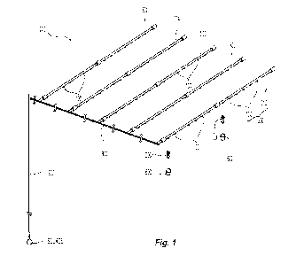
over an area to be protected. To control fluid discharge from the sprinkler
body is a fusible or
thermally responsive trigger assembly which secures a seal over the central
orifice. When the
temperature surrounding the sprinkler is elevated to a pre-selected value
indicative of a fire,
the trigger assembly releases the seal and water flow is initiated through the
sprinkler. The
spray pattern or distribution of a firefighting fluid from a sprinkler defines
sprinkler
performance. Several factors can influence the water distribution patterns of
a sprinkler
including, for example, the shape of the sprinkler frame and the geometry of
the deflector. The
deflector geometry can define the size, shape, uniformity, and water droplet
size of the spray
pattern.
[0004]
The fluid discharge from the sprinkler body also impacts sprinkler
performance.
The discharge or flow characteristics from the sprinkler body is defined by
the internal
geometry of the sprinkler including its internal passageway, inlet and outlet
(the orifice).
- 1 -
CA 03206616 2023- 7- 26
WO 2022/178179
PCT/US2022/016868
Generally, the size of the sprinkler discharge orifice is defined by the
nominal K-factor of a
sprinkler. For a given sprinkler assembly, the larger the K-factor, the larger
the discharge
orifice, and the smaller the K-factor, the smaller the discharge orifice.
Nominal K-factors for
sprinklers listed in the National Fire Protection Association Standard
Publication, NFPA 13:
Standard for the Installation of Sprinkler Systems, can range from 1 to 30
[GPM/(psi.)1/21 and
greater. As is known in the art, the K-factor of a sprinkler is defined as K =
Q/P1/2 , where Q
represents the flow rate (in gallons/min GPM) of water from the outlet of the
internal passage
through the sprinkler body and P represents the pressure (in pounds per square
inch (psi.)) of
water or firefighting fluid fed into the inlet end of the internal passageway
through the sprinkler
body. Accordingly, the designed performance of a sprinkler is a function of
the supply of a
minimum fluid pressure or flow. Thus, any restriction to the fluid flow supply
to a sprinkler
can negatively impact the performance of a sprinkler.
[0005]
Automatic fire protection sprinklers are used, for example, in the
protection of
storage commodities and occupancies. Storage fire protection systems include a
network of
pipes connected to a firefighting fluid supply source and installed above the
storage commodity
beneath the ceiling of the occupancy. The piping network includes one or more
branch lines
coupled to a cross-main which is connected to a fluid supply by a vertical
piping riser to supply
the branch line(s) with the firefighting fluid. Fire protection sprinklers are
connected to the
branch lines in an appropriate orientation and at an appropriate sprinkler-to-
sprinkler spacing.
[0006] To connect
the fire protection sprinklers to the branch lines, the branch lines are
configured as linear pipe headers with branch connectors extending from the
header for receipt
and threaded connection of a fire protection sprinkler. Known connectors have
one inlet end
configured for welded connection to the pipe header and an opposite outlet end
with a tapered
threaded end for connection of a sprinkler. In order to form a fluid tight
seal between the
threadedly engaged connector and the sprinkler, a sealing tape or putty is
applied to the
sprinkler. This can be labor intensive and add to the installation time.
Moreover, in order to
form a fluid tight seal between the cooperating tapered threads, the sprinkler
must be properly
torqued using a wrench. Although a fluid tight seal is formed, the sprinkler
may not be properly
rotationally oriented for sprinkler operation.
[0007] There are
known branch connectors which eliminate either or both of the tapered
thread connection or the need to apply a sealing tape or putty. For example,
each of U.S. Patent
Nos. 8,297,663 and 10,744,527, U.S. Patent Publication No. 2019/0175968 and
Korean Patent
-2-
CA 03206616 2023- 7- 26
WO 2022/178179
PCT/US2022/016868
Publication No. KR20040108608A show and describe connectors or adapters for
connecting a
fire protection sprinkler to a pipe header. Each of U.S. Patent No.
10,744,527, and U.S. Patent
Publication No. 2019/0175968 use an internal straight thread at the outlet to
connect the tapered
thread of the fire protection sprinkler, which allows the sprinkler to be
placed in a desired
rotational orientation without the interference of the thread engagement. To
form a fluid tight
seal between the connector and the sprinkler, each of U.S. Patent Nos.
8,297,663 and
10,744,527, U.S. Patent Publication No. 2019/0175968 and Korean Patent
Publication No.
KR20040108608A employ an internal annular seal member which eliminates the
need to apply
a separate sealing tape or putty. In forming the fluid tight seal, the seal
member is compressed
against the internal surface of the connector. One area of concern in using an
internal sealing
member is the need to make sure that the compression of the seal does not
restrict the fluid
flow supply through the connector to the sprinkler which can negatively impact
the discharge
and distribution from the sprinkler. Some of the patent documents describe a
geometric
solution to minimize fluid flow interference. For example, U.S. Patent No.
10344,527
describes seal member geometries that, in combination with the internal
geometry of the
connector, prevent or eliminate restriction to the fluid flow through the
connector that would
negatively impact sprinkler performance. U.S. Patent Publication No.
2019/0175968 describes
an alternate solution in which the connector includes an expansion volume
above or axially
adjacent the seal member into which the distorted seal member can expand.
[0008] The prior
art presents connectors that include a seal and provide methods to
eliminate or minimize a restrictive flow through the connector; however, the
prior art raises
additional concerns or problems in the connector structure. For example, U.S.
Patent No.
8,297,663 describes that the seal member is still permitted to distort
radially inwardly in the
direction of the fluid flow path. U.S. Patent Publication No. 2019/0175968,
KR20040108608A
and PCT Patent Publication No. WO 2021/186369 add complexity to the connector
assembly
because each of these patent documents show and describe connectors using a
multi-
component assembly in addition to the separate annular seal. For example, U.S.
Patent
Publication No. 2019/0175968 describes a branch connector with a multi-piece
tube or housing
that uses a threaded connection therebetween that relies on the same annular
seal to form a
fluid tight seal between the housing components. KR20040108608A shows and
describes an
internal locking ring in addition to an internal sealing member in order to
retain the fire
protection sprinkler in the branch connector.
-3-
CA 03206616 2023- 7- 26
WO 2022/178179
PCT/US2022/016868
[0009]
Additionally, branch connectors shown in each of U.S. Patent Nos.
8,297,663 and
10,744,527, U.S. Patent Publication No. 2019/0175968, Korean Patent
Publication No.
KR20040108608A and PCT Patent Publication No. WO 2021/186369 add complexity to
the
fire protection system installation. The connectors described in each of these
patent documents
receive a pipe fitting or conduit that is connected to the pipe header in
order to receive the
supplied firefighting fluid. The conduit is inserted into the inlet opening of
the connector and
firefighting fluid is then introduced internally downstream of the point of
insertion. These
known connectors have an internal surface that circumferentially surrounds the
conduit and
includes a stepped surface that provides an internal annular shelf to support
the inserted end of
the fluid carrying conduit. The annular shelf is defined by a transverse
portion of the stepped
surface that extends radially inward transverse to the internal passageway of
the connector.
The annular shelf is also defined by an axially extending portion of the
stepped surface that
runs parallel to the internal passageway of the connector. Collectively, the
transverse and
axially extending portions of the stepped surface form the annular shelf as a
cantilevered
structure off of the internal surface of the connector. These connectors can
be affixed to the
inserted supply conduit by an adhesive applied internally into the connector.
[0010]
Other known branch connectors are shown and described in PCT Patent
Publication No. WO 2021/198812 that are directly welded to the pipe header and
therefore
eliminate the need for an inlet surface configured for receipt of a supply
conduit. However,
the described connector adds complexity to the system assembly and
installation because the
connector is used with a fire protection sprinkler in which the seal member is
attached to the
sprinkler. Thus, branch connectors shown and described in PCT Patent
Publication No. WO
2021/198812 require a particular seal and sprinkler configuration to form a
proper seal. The
particular arrangement shows the internal thread of the connector between the
fluid inlet and
the annular seal. With the seal shown housed near the open end of the
connector, the seal can
be exposed to the surrounding environment which can damage the seal.
[0011]
Placement of the annular seal member is important to forming a proper seal
regardless of where the seal is in a branch connector. U.S. Patent No.
10,744,527 describes
positioning and orienting an annular seal member internally within the
connector to form a
proper seal with an inserted fire protection sprinkler. There are known
commercially available
tools to insert the seal member into the connector. These installation tools
employ a plunger
and nozzle that engage the connector to insert the seal member. The plunger
uses a handle
-4-
CA 03206616 2023- 7- 26
WO 2022/178179
PCT/US2022/016868
arrangement similar to a caulking gun to drive the plunger to drive the seal
member through
the nozzle and into the proper place and orientation within the connector. One
problem with
this known installation tool is that the gun-like handle is bulky and can be
difficult in tight
spaces in which there may be obstructions.
[0012] Given the
installation complexity and operational concerns with known branch
connectors, there remains a need for a simplified internal sealing assembly
and arrangement in
branch connectors that can couple fire protection devices to system piping in
a sustainable
fluid-tight manner while providing adequate fluid flow to the devices for
effective fire
protection.
Disclosure of the Invention
[0013]
Preferred embodiments of fire protection systems and methods are provided
in
which the systems and methods use preferred piping interconnections between
fire fluid
devices and a source of firefighting fluid. The piping interconnections
include a preferred
branch connector for connecting a fire protection device to a pipe header in a
network of pipes
of the fire protection system. Preferred embodiments of the branch connector
include a
preferably unitary tubular member having a first end for direct connection to
the supply pipe
header, a second end for connection to the fluid distribution device, and an
internal passageway
extending along a central longitudinal axis from the first end to the second
end. The internal
passageway preferably includes an internally threaded portion proximate the
second end for
coupling to the fluid distribution device, a fluid intake portion proximate
the first end for intake
of firefighting fluid from the pipe header and a preferred internal gasket
chamber formed
between the threaded and fluid intake portions to house an annular seal
member. The fluid
intake portion preferably extends from the first end to the gasket chamber and
is preferably
configured for direct fluid contact. Without the need to support an inserted
fluid supply
conduit, the internal surface defining the fluid intake portion of the branch
connector is stepless.
That is, as used herein, "stepless" means that the internal surface does not
include a surface
that extends transversely and axially parallel to the internal passageway to
provide an internal
annular shelf for support of an inserted conduit. The internal surface in
preferred embodiments
of the branch connector described herein define the gasket chamber with a
first restriction and
an axially spaced second restriction of the passageway to support the annular
seal member with
a relief wall between the first and second restriction to define an expansion
volume about the
annular seal member.
-5-
CA 03206616 2023- 7- 26
WO 2022/178179
PCT/US2022/016868
[0014]
A preferred embodiment of a fire protection system includes a network of
pipes for
interconnecting fire protection devices to a source of firefighting fluid. The
system and its
network of pipes include a pipe header having an internal fluid passageway
extending along a
longitudinal axis with an opening formed radially about the longitudinal axis.
A preferred
branch connector is connected to the pipe header. The branch connector
includes a unitary
tubular member having a first terminal end, and a second terminal end spaced
from the first
terminal end. The unitary tubular member includes a gasket chamber surface
between the first
terminal end and the second terminal end with a single annular seal member
housed in the
tubular member and supported therein by the gasket chamber surface. An
internally threaded
surface is formed between the gasket chamber surface and the second terminal
end, and an
internal stepless surface extends from the first terminal end to the gasket
chamber surface. The
first terminal end is preferably welded about the opening in the pipe header
with the stepless
surface in fluid communication with the internal fluid passageway of the pipe
header. The
system also includes a fire protection device coupled to the branch connector.
The device
includes a frame having a frame body with a frame inlet, a frame outlet and a
frame internal
passageway extending from the frame inlet to the frame outlet along a device
axis. The device
can include a fluid deflection member coupled to the device frame and the
frame body is in a
threaded engagement with the internally threaded surface of the tubular member
to compress
the annular seal member and establish the fire protection device in fluid
communication with
the fluid passageway of the pipe header.
[0015]
Another preferred embodiment of the fire protection system includes a
network of
pipes for connecting fire protection devices to a source of firefighting
fluid. The network of
pipes has branch lines that includes a pipe header having internal fluid
passageway extending
along a longitudinal axis with an opening formed therein radially about the
longitudinal axis.
The branch lines also include a branch connector having an annular seal member
and a unitary
tubular member. The tubular member has a first terminal end welded to the pipe
header, and a
second terminal end spaced from the first terminal end. The unitary tubular
member includes
an internal surface extending from the first terminal end to the second
terminal end and
circumscribed about a central axis of the tubular member extending
perpendicular to the
longitudinal axis of the pipe header. The internal surface includes a gasket
chamber surface
with the annular seal member housed and supported in the tubular member by the
gasket
chamber surface, an internally threaded surface between the gasket chamber
surface and the
-6-
CA 03206616 2023- 7- 26
WO 2022/178179
PCT/US2022/016868
second terminal end for engaging a fire protection device, and a stepless
surface in fluid
communication with the internal fluid passageway of the pipe header. The
stepless surface
extends from the first terminal end to the gasket chamber surface.
[0016]
Preferred methods of providing system fire protection include placing an
annular
seal member in an unloaded condition within an internal gasket chamber formed
along an
internal surface extending along and circumscribed about a central axis of a
preferred unitary
tubular member. The gasket chamber is preferably located between an internally
threaded
surface and an internal stepless surface of the internal surface. The
internally threaded surface
is between the gasket chamber and a terminal outlet end of the tubular member,
and the internal
stepless surface preferably extends from the gasket chamber to a terminal
inlet end of the
tubular member in a welded connection to a pipe header of a network of pipes.
The preferred
method includes placing the annular seal member in a loaded condition within
the internal
gasket chamber with a fire protection device frame in threaded engagement with
the internally
threaded surface and fluid communication with the pipe header.
[0017] One
preferred embodiment of a branch connector for fire protection systems and
methods described herein include an annular seal member having a first end
seal surface, a
second end seal surface, an inner surface defining an inner gasket diameter
and a peripheral
surface defining an outer gasket diameter. The tubular member has an inlet for
connection to
the supply pipe header, an outlet for connection to a fire protection fluid
distribution device,
and an internal surface defining an internal passageway extending along a
central longitudinal
axis from the inlet to the outlet. The internal passageway defines a minimum
diameter for
firefighting fluid to flow therethrough. The internal passageway also includes
a preferred
gasket chamber formed between the inlet and the outlet with the annular seal
member disposed
in the gasket chamber. The gasket chamber is preferably defined by a first
restriction proximate
the inlet; a second restriction proximate the outlet with a relief wall
between the first restriction
and the second restriction. The first and second restriction engaging the
peripheral surface of
the annular seal member to support the annular member within the gasket
chamber such that
the relief wall circumscribes the peripheral surface to define an expansion
volume
therebetween with a fluid flow path extending from the inlet to the outlet and
through the inner
surface of the annular seal member. Accordingly, a preferred method of
connecting a fire
protection fluid distribution device to a fluid supply pipe header is also
provided. The preferred
method includes providing an inlet end of a tubular member welded to the fluid
supply pipe
-7-
CA 03206616 2023- 7- 26
WO 2022/178179
PCT/US2022/016868
header; and radially expanding the annular seal member with the fluid
distribution device
threaded into an outlet of the tubular member such that the annular seal
member radially
expands into an expansion volume defined between two restrictions supporting
the seal
member about a central longitudinal axis of the tubular member.
[0018] Preferred
embodiments of a tool for installing an annular seal member in an
internal gasket chamber of a branch connector for fire protection fluid
distribution devices is
also provided. A preferred tool includes a nozzle member having a first end
face and a second
end face axially spaced from the first end face with an internal passageway
for holding an
annular seal member therein. The internal passageway extends axially from the
first end face
to the second end face along a central longitudinal axis. The tool also
includes a plunger
member having a rod portion with a handle portion at one end of the rod
portion and a free end
opposite the handle portion. The rod portion is disposed in the internal
passageway of the
nozzle member for a sliding engagement. The sliding engagement defines a first
position of
the plunger member with the handle portion axially spaced from the second end
face of the
nozzle member with the free end of the rod portion proximate the annular seal
member within
the second internal passageway and a second position of the plunger member
with the handle
portion proximate the second end face of the nozzle member such that the free
end of the rod
portion ejects the annular seal member out of the internal passageway. The
handle portion is
preferably centered and coaxially aligned in each of the first and second
positions. The rod
portion is affixed centrally to the handle portion so as to expose a base
surface of the handle
portion. More preferably, the handle portion has a periphery that uniformly
circumscribes a
central axis of the tool. The handle portion preferably has a diameter greater
than the rod
portion so that the exposed base surface of the handle portion contacts the
nozzle portion in the
second position of the plunger member. The first position of the plunger
member defines a
first operational length of the tool that ranges from three to 2-1/2 times a
length of the tubular
member of the branch connector from the inlet to the outlet and the second
position defines a
second operational length of the tool that ranges from 1.5 to 1 times the
length of the tubular
member of the branch connector.
Brief Description of Drawings
[0019] The
accompanying drawings, which are incorporated herein and constitute part of
this specification, illustrate exemplary embodiments of the invention, and
together, with the
general description given above and the detailed description given below,
serve to explain the
-8-
CA 03206616 2023- 7- 26
WO 2022/178179
PCT/US2022/016868
features of the invention. It should be understood that the preferred
embodiments are some
examples of the invention as provided by the appended claims.
[0020] FIG. 1 is an illustrative schematic view of a preferred
embodiment of a fire
protection system.
[0021] FIG. IA is an exploded cross-sectional view connecting a preferred
illustrative fire
protection device to a fluid supply pipe header and preferred branch connector
in the system of
FIG. 1.
[0022] FIG. 2 is a partial cross-sectional view illustrating
connection of the fire protection
device to the pipe header using the branch connector of FIG. IA.
[0023] FIG. 2A is a partial illustrative detailed cross-sectional view
showing an annular
seal member loaded by the connected device in the branch connector of FIG. 2.
[0024] FIG. 2B is a perspective exploded view of the preferred
embodiment of the device
of FIG. 1A and a preferred protective installation device for use in the
system of FIG. 1.
[0025] FIG. 2C is a partial illustrative cross-sectional
exploded view of the protected
device assembly of FIG. 2B, pipe header and the preferred branch connector of
FIG. 2.
[0026] FIG. 2D is a partial illustrative cross-sectional view of
the interconnected protected
device assembly of FIG. 2B, pipe header and the preferred branch connector of
FIG. 2.
[0027] FIG. 3A is a cross-sectional view of the branch connector
of FIG. lA with the
annular seal member in an unloaded state.
[0028] FIG. 3B is a detailed cross-sectional view of the branch connector
in FIG. 3A.
[0029] FIG. 4 is a cross-sectional view of a preferred annular
seal member for use in the
branch connector of FIG. 3A.
[0030] FIG. 5A is an exploded perspective view of a preferred
installation tool for use
with the branch connector of FIG. 3A.
[0031] FIG. 5B is a cross-sectional view of the preferred installation tool
and branch
connector of FIG. 5A.
[0032] FIG. 5C is another cross-sectional view of the preferred
installation tool and branch
connector of FIG. 5A.
-9-
CA 03206616 2023- 7- 26
WO 2022/178179
PCT/US2022/016868
Mode(s) For Carrying Out the Invention
[0033]
Shown in FIG. 1 is an illustrative schematic embodiment of a fire
protection system
that uses a preferred interconnection between a fire protection device 200 and
a network of
pipes 1000. Generally, the network of pipes 1000 couples the fire protection
devices 200 to a
supply of firefighting fluid (SOURCE), for example, a water main. Moreover,
the network of
pipes 1000 locate the devices 200 over an area or occupancy to be protected.
For example, the
system can be configured for protection of a storage occupancy by locating the
devices in the
ceiling above the storage and supplying the devices 200 with water. In the
system shown, the
network of pipes 1000 includes a vertical riser 900 coupled to the fluid
supply source, a cross-
member 800 coupled to the riser 900; and a plurality of spaced apart branch
pipes 300 to which
the devices 200 are connected. Each of the branch pipes 300 includes a pipe
header 310 and a
plurality of branch connectors 100 into which the devices are threadedly
connected. In each
branch pipe 300, the branch connectors 100 are welded to the pipe header 310
and are
preferably linearly spaced apart from one another. The preferred system 1000
includes a
preferred interconnection between externally threaded fire protection devices
200 and
internally threaded branch connectors 100 in which the devices can be threaded
into the fittings
and more preferably hand threaded into the fittings to engage an internal seal
to form a fluid-
tight engagement and rotationally orient the device in a manner for effective
fire protection.
As described herein preferred embodiments of a protective installation tool
600 can be used to
install the devices in the branch connectors 100.
[0034]
Shown in FIG. 1A is a cross-sectional exploded view of a preferred
embodiment
of a preferred interconnection in which an externally threaded fire protection
device 200,
illustratively shown as a sprinkler 200, is threaded into a preferred branch
connector 100 to
couple and place the sprinkler into fluid communication with a pipe header
310. The branch
connector 100 includes a generally tubular member 10 having a first inlet end
12 for fluid
connection to the pipe header 310 and a second outlet end 14 for receipt of a
fire protection
sprinkler 200. The branch connector also includes a preferably single annular
seal member
400 housed in a gasket chamber 30 positioned between the first and second ends
12, 14 for
forming a fluid tight sealed engagement with the sprinkler 200 that is in a
threaded engagement
with an internal thread 20 of the tubular member 10. In preferred embodiments
of the system,
the pipe header 310 has internal fluid passageway 312 extending along a
longitudinal axis Y--
Y with an opening 314 formed therein radially about the longitudinal axis Y--
Y. In the
-10-
CA 03206616 2023- 7- 26
WO 2022/178179
PCT/US2022/016868
preferred branch connector 100 the tubular member is a preferably unitary
tubular member 10
having a first terminal end 12, and a second terminal end 14 spaced from the
first terminal end
12. The first terminal end is preferably welded about the opening 314 in the
pipe header 310.
The unitary tubular member 10 includes an internal surface 15 that is
preferably circumscribed
about a central tubular axis X--X and the internal surface 15 extends from the
first terminal end
12 to the second terminal end 14 to define an internal passage 16 of the
tubular member 10.
The internal surface 15 preferably includes a gasket chamber surface 30
between the first
terminal end 12 and the second terminal end 14 to define the preferred
internal gasket chamber
for housing and supporting the annular seal member 40 therein. An internally
threaded surface
20 of the tubular member is preferably formed between the gasket chamber
surface 30 and the
second terminal end 14. In preferred embodiments of the tubular member 10, an
internal
stepless surface 15 extends from the first terminal end 12 to the gasket
chamber surface 30 for
fluid communication with the internal fluid passageway of the pipe header 310.
In the system
interconnections, a fire protection sprinkler 200 is in a threaded engagement
with the internally
threaded surface 20 of the tubular member 10 to compress the annular seal
member and
establish the fluid communication between the fire protection sprinkler 200
and the fluid
passageway 312 of the pipe header 310. With the tubular member preferably
welded to the
pipe header 310, the stepless surface is in direct contact with the supplied
firefighting fluid;
and thus, a stepped internal surface for engaging an inserted supply conduit
can be eliminated.
[0035] Generally,
a fire protection device 200 includes a frame 210 having a frame body
212 with a frame inlet 214, a frame outlet 216 and an internal sprinkler
passageway 218
extending from the frame inlet 214 to the frame outlet 216 along a central
sprinkler axis to
define a nominal K-factor of, for example, 8.0 lGPM/(psi.)1/21 or greater. The
body 212
preferably includes an external thread 220 for forming a preferred threaded
engagement with
the branch connector 100. The device, such as sprinkler 200 can include a
fluid deflection
member 222 coupled to the sprinkler frame 210 for distributing firefighting
fluid discharged
from the frame outlet 216 to effectively address a fire. The sprinkler 200
preferably is
configured as an automatic fire protection device in which a thermally
responsive assembly
224, in combination with a seal assembly 226, maintains the fluid outlet 216
sealed in an
unactuated state. In the presence of a sufficient level of heat, for example a
fire, the thermally
responsive assembly 224 actuates to release the seal 226 and open the frame
outlet 216 to
permit the discharge of firefighting fluid. The fluid deflection member 222
can be at a fixed
-11 -
CA 03206616 2023- 7- 26
WO 2022/178179
PCT/US2022/016868
distance from the frame outlet 216 as shown or alternatively be movable, for
example, to axially
translate with respect to the frame outlet 216 from an unactuated position to
an actuated
position to distribute the discharged firefighting fluid. Depending upon the
configuration of
the fluid deflection member, the device 200 can be a pendent, an upright or a
sidewall/horizontal device.
[0036]
The branch connector 100 is preferably a straight fitting or alternatively
can be
formed as a different type of fitting, such as for example, an elbow fitting
or tee fitting to
connect an appropriately configured sprinkler. With reference again to FIGS.
1A and 2,
preferred tubular member 10 of the branch connector 100 and its internal
surface 15 defines
the internal passageway 16 preferably extending along the central longitudinal
axis X--X from
the first end 12 to the second end 14. The internal passageway 16 preferably
includes a fluid
intake portion 18 proximate the inlet end 12 for intake of firefighting fluid
from the pipe header
310. The preferably stepless surfaces 15a, 15b defines the fluid intake
portion 18. The internal
surface 15 includes the preferred internally threaded portion 20 proximate the
outlet end 14 for
receipt of and coupling to the fire protection sprinkler 200. The internal
passageway 16
preferably includes the gasket chamber 30 formed between the fluid intake
portion 18 and the
internally threaded portion 20 to house an annular seal member 400. The
surfaces defining the
chamber 30 preferably include a backstop surface 40 against which the seal
member 400 forms
a fluid-tight sealed engagement when the seal member 400 is engaged and loaded
by the
sprinkler 200.
[0037]
As previously described the tubular member 10 is preferably formed as
single-
piece, monolithic or unitary structure. Moreover, the tubular member 10 is
preferably formed
or fabricated from a weldable material such as for example, steel or a
weldable grade iron for
welded connection to the pipe header 310. In preferred embodiments of the
tubular member
10, the first terminal inlet end 12 defines a saddle-shaped surface, as more
clearly seen in FIG.
3A, that is circumscribed about the central tubular axis X--X. The preferred
saddle-shaped
inlet end 12 defines a radius of curvature R about an axis extending
perpendicular to and
intersecting the central tubular axis X--X. The preferred saddle shaped inlet
end 12 is
configured to cradle the fluid supply pipe header 310 in a preferred welded
connection.
Moreover, as seen in FIG. 2, the inlet end surface 12 can be preferably tiered
to define a portion
that is disposed within the opening of the pipe header 310 and another portion
outside the
header opening that is incorporated in the preferred welded connection. With
reference again
-12-
CA 03206616 2023- 7- 26
WO 2022/178179
PCT/US2022/016868
to FIG. 3A, the inlet surface 15 is preferably contiguous with the inlet end
12 to define the
preferred fluid intake portion 18 of the internal passageway 16 and its first
internal diameter
Dial for fluid communication with the pipe header 310. The inlet end 12 and
the inlet diameter
Dial defines a preferred ratio of radius of curvature R-to-diameter Dial that
ranges from 1.3:1
to 1:1.
[0038]
With reference to FIG. 3A, the fluid intake portion 18 of the tubular
member
preferably extends from the first inlet end 12 to the gasket chamber 30 and
more preferably
axially extends from the first terminal inlet end 12, then tapers and
terminates at the sealing
surface 40 of the gasket chamber 30. In the preferred embodiment, the fluid
intake portion 18
includes a first portion 18a in which a first preferably stepless segment 15a
of the internal
surface 15 defines the preferably constant first internal diameter Dial of the
passageway 16.
A second portion 18b of the fluid intake portion 18 preferably defines a
second internal
diameter Dia2 that is variable and defined by a second preferably stepless
segment 15b of the
internal surface 15 that is preferably contiguous with the first segment. The
second segment
15b of the stepless internal surface 15 defining the second portion 18b of the
fluid intake portion
18 defines a profile from the first segment 15a to the backstop surface 40 to
define the tapering
second portion 18b of the fluid intake portion 18.
[0039]
The second portion 18b of the fluid intake portion 18 preferably forms a
tapering
portion of the internal passageway 16 that tapers between the first portion
18a of the fluid intake
portion 18 and the backstop surface 40 and preferably varies from a maximum
equal to the first
diameter Dial to a minimum equal to the minimum diameter MinDIA of the
internal
passageway 16. In the preferred tubular member 10, the first segment 15a of
the internal
surface 15 extends parallel to the central axis X--X to define a preferred
constant diameter first
part 18a of the fluid intake portion 18 over the first segment 15a. The first
segment 15a is
preferably between and contiguous with each of the first end 12 of the tubular
member 10 and
the second segment 15b of the internal surface. The second segment 15b is
skewed with respect
to the central axis X--X to define a preferred constant slope between and
contiguous with each
of the first segment 15a and the backstop surface 40 of the gasket chamber 30.
Accordingly,
the second segment 15b defines the preferred narrowly tapering diameter part
18b of the fluid
intake portion 18 with the second segment 15b being between and contiguous
with each of the
first segment and the backstop surface 40 of the gasket chamber.
-13-
CA 03206616 2023- 7- 26
WO 2022/178179
PCT/US2022/016868
[0040]
The second outlet end 14 of the tubular member 10 and the internally
threaded
portion 20 of the internal passageway 16 are preferably configured for receipt
and connection
with the sprinkler 200 of a nominal size. Accordingly, preferred embodiments
of the branch
connector 100 at the outlet end 14 can define a nominal size or diameter
ranging from 1/2 inch
to 1-1/2 inch and more particularly any one of 1/2 inch, 3/4 inch, and even
more preferably any
one of a nominal 1 inch, 1-1/4 inch or 1-1/2 inch and suitable for receipt of
a fire protection
device having a nominal K-factor of 8.0 [CIPM/(psi.)1/21 or greater and more
preferably, any one
of 22.4; 25.2; 28.0; 30.5; 33.6 I CiPM/(psi.)1/21. The overall length L of the
branch connector
between the inlet end 12 and the outlet end 14 preferably ranges from 1 inch
to 1-1/2 inch. The
second terminal outlet end 14 is preferably defined by a circular planar
surface circumscribed
and disposed orthogonally with respect to the central axis X--X. The length L
of the branch
connector 100 is preferably defined between the outlet end 14 and a mid-point
of the concave
portion of the saddle-shaped inlet 12. Moreover, the overall length L of the
branch connector
100 preferably corresponds or varies with the outlet nominal diameter size.
For example, for
a nominal outlet diameter of 1 inch, the length L is preferably 1-1/4 inch,
where the nominal
outlet diameter is 3/4 inch, the length L is preferably 1-1/8 inch and where
the nominal outlet
diameter is 1/2 inch, the length L is preferably 1-1/16 inch. Accordingly, the
preferred tubular
member 10 defines a preferred ratio of Length L-to-nominal outlet diameter
that ranges from
1.25-2.1, can be any one of 1.25:1; 1.125:1 or 1.06:1 and is preferably 1.25-
1.
[0041] With
reference again to FIGS. 1A, 2 and 2A, the frame body 212 of the sprinkler
200 includes an external thread 220 for a threaded engagement with the
internally threaded
portion or surface 20 of the tubular member 10 with the frame body 212 in
sealing engagement
with the annular seal member 400. The annular seal member 400 is axially
located between
the fluid intake portion 18 and the threaded engagement, to place the internal
passageway 218
of the sprinkler 200 in fluid communication with the internal passageway 16 of
the tubular
member 10. Generally, the external thread 220 of a fire protection sprinkler
200 is of a tapered
form, for example, NPT thread. The internal threaded portion 20 preferably
includes an
internal straight thread 22 for receipt of the tapered sprinkler thread of the
sprinkler 200. The
threaded engagement remains sealed from fluid supplied through the inlet end
12 by the proper
fluid tight seal sealed engagements between the seal member 400 and the
backstop surface 40
and between the sprinkler 200 and the annular seal member 400. The internal
diameter ID of
the internal straight thread 22 can be defined by any one of the pitch
diameter, minor diameter
-14-
CA 03206616 2023- 7- 26
WO 2022/178179
PCT/US2022/016868
or major diameter of the internal thread 22 provided the straight thread
engages the tapered
thread of the sprinkler 200. The internal straight thread can be for example,
a 1-11.5 NPSH
Thread; a 3/4 - 14 NPSH Thread; or a 1/2-14 NPS Thread for mating with a
correspondingly
nominal 1 inch, 3/4 inch or 1/2 inch fire protection sprinkler.
[0042] Use of
the preferred straight internal thread permits the tapered threaded sprinkler
200 to be rotatable about the axis X--X within the connector 10 such that the
device 200 can
be rotationally oriented, preferably by hand, in any desired position while
forming a proper
fluid tight seal. More preferably, the internal thread portion 20 and the seal
member 400 form
a proper fluid tight seal engagement with the device 200 upon sufficient
rotation by hand of
the device following contact with the seal member 400. Accordingly, in the
preferred branch
connector 100, the sprinkler 200 deforms the annular seal member 400 to
provide a leak-proof
fluid-tight seal between the device 200 and the connector 10 requiring a
preferred lower torque
as opposed to the higher torque that would be required in a typical fire
protection sprinkler
installation using a wrench and cooperating tapered threads. The preferred
connector 10 can
provide for a fluid tight seal between the connector 10 and a threaded device
200 under a fluid
pressure of up to 200 psi or more, for example, pressures of up to and
including at least 175
psi-
[0043]
Alternatively or additionally, the preferred interconnection can include a
preferred
hand operated protective device 600 disposed about the sprinkler 200 for
installing the fire
protection sprinkler 200. Shown in FIGS. 2B, 2C and 2D are varying views,
including
exploded, partial cross-sectional and perspective views, of the sprinkler
assembly 200 and a
protective device 600 for installation in the preferred branch connector 100.
Preferred
embodiments of the protective device 600 protects the sprinkler 200 from
unintentional impact
and damage during storage, transport, installation and/or when awaiting to be
placed into
service. Moreover, the protective device 600 also serves as a tool for
installing the sprinkler
200 into the branch connector 100. A preferred device 600 facilitates
installation of the
sprinkler 200 by transferring an applied hand torque to install the sprinkler
200 into the branch
connector 100 in a fluid tight manner as described herein.
[0044]
The protective installation device 600 is preferably formed from a polymer
or
plastic material such as, for example, polyethylene and formed by molding such
as, for
example, injection molding. The device 600 is preferably formed as a tubular
cap having a
first end 604 defining an opening for axially receiving the fire protection
sprinkler 200 and an
-15-
CA 03206616 2023- 7- 26
WO 2022/178179
PCT/US2022/016868
opposite second end 606 coaxially centered and axially spaced from the first
end 604. The
tubular cap 602 defines an internal void 608 and volume for housing a portion
of the received
sprinkler 200. The tubular cap 602 includes a shielding wall portion 612 that
preferably
extends between the first end 604 and the second end 606 to define the
internal void 608.
Moreover, preferred embodiments of the cap 600 and its wall portion 612 define
preferred
torque assist features 650 of the device 600. Generally, the torque assist
feature 650 includes
one, and preferably more than one, external rotational drive formations for
applying a torque
to the sprinkler 200 and one, and preferably more than one, internal
rotational drive formations
for transferring the applied torque to the sprinkler 200 for rotation within
the preferred threaded
branch connector 100 to form a fluid tight connection therebetween. For
example, the wall
612 of the cap 600 shown defines internal and external torque assist features
650 of the device
600. The external surface of the wall 612 preferably includes a formation in
the form of a
planar external surface 652 that can serve as a lever surface against which an
installer or user
can press a thumb or finger(s) to apply a preferred hand torque. Internally,
the device 600
includes at least one and preferably includes two diametrically opposed
internal gripping
formations or portions 654 to grip the sprinkler frame 210. Preferred
embodiments of the
sprinkler frame 210 include two frame 230a, 230b spaced apart the frame body
212. Each
gripping portion 654 defines an internal channel that extends axially
preferably from the first
end 604 to the second end 606 of the cap 600. The channels of the gripping
portion 654 also
defines a channel width in the angular direction about the device axis and a
channel depth in a
radial direction from the device axis. The frame arms 230a, 230b are axially
received within
the channels of the gripping formations 654. Preferred configurations of the
gripping portions
654 channels facilitate the protective device 600 forming a preferred
frictional surface
engagement with the sprinkler 200 that prevents or minimizes relative rotation
between the
device 600 and the sprinkler 200 in order to apply the torque to the sprinkler
200 for installation
into the preferred branch connector 100 in a fluid tight manner.
[0045]
With reference to FIGS. 2C and 2D, the protective device 600 is located
about the
sprinkler 200 to axially extend from the frame body 212 to the fluid
deflection member 222.
Additionally, the protective device 600 is preferably disposed about the frame
210 to expose
the wrench boss of the sprinkler frame for use of the protective device in
combination with a
wrench to install the sprinkler. Notwithstanding, preferred embodiments of the
protected
sprinkler assembly 200, 600 are configured for hand installation using the
device 600 to form
-16-
CA 03206616 2023- 7- 26
WO 2022/178179
PCT/US2022/016868
a fluid tight connection with the branch connector 100. The protective device
600 extends
axially to the fluid deflection member 222 to house the fluid deflection
member 222 and more
preferably peripherally surround the fluid deflection member 222. Moreover,
the preferred
protective device 600 houses and protects the thermally responsive trigger
224. The device
600 preferably tapers or narrows in the axial direction from the first end 604
toward the second
end 606. With reference to FIG. 2D, the internal surface of the device 600 can
include one or
more circumferentially extending ribs or projections to form a surface
engagement and more
preferably a snap-fit engagement with the fluid deflection member 222 of the
inserted sprinkler
200 to secure the device 600 to the sprinkler 200. Additional features of a
protective device
600 are shown and described in U.S. Provisional Application No. 63/247,630,
filed September
23, 2021, which is incorporated by reference in its entirety.
[0046]
As described herein, the branch connector 100 includes a preferred
internally
formed gasket chamber 30 in which an annular seal member 400 is disposed.
Firefighting fluid
fed into the inlet end 12 flows through the annular seal out the outlet end 14
to supply the
sprinkler 200 for discharge and distribution in accordance with the
performance specification
of the sprinkler 200. As shown in FIG. 3A, the gasket chamber 30 provides for
a preferred
expansion volume 38 or gap about the seal member 400 into which the seal can
expand and/or
deform radially outwardly. By providing the radial outward expansion volume
38, the inner
area of the annular seal member 400 is maintained and/or maximized so as to
minimize or
prevent any restriction to the flow therethrough, thereby supplying a flow of
fluid to the
sprinkler 200 that maintains the discharge and distribution of fluid from the
sprinkler 200.
[0047]
Generally, the preferred internal gasket surfaces of the tubular member 10
that
form the chamber 30 include two axially spaced apart radial restrictions 32,
34 to radially
compress, support and locate the seal member 400 within the gasket chamber 30.
The internal
surface 15 defining the gasket chamber 30 includes a preferred relief wall 36
that preferably
extends between the two restrictions 32, 34 that circumscribes the supported
seal member 400
to define a preferred radial expansion volume 38 therebetween. As shown in
FIG. 4, the
annular seal member 400 includes a peripheral or outer wall surface profile
that defines an
outer gasket diameter OGD and an inner wall surface profile that defines an
internal gasket
diameter IGD. Either one or both of the outer and inner gasket diameters OGD,
IGD can be
constant or alternately vary over the axial length or height of the seal
member 400. In preferred
embodiments of the annular seal member 400, the inner gasket diameter IGD is
80% of the
-17-
CA 03206616 2023- 7- 26
WO 2022/178179
PCT/US2022/016868
maximum outer gasket diameter OGD. FIG. 3A illustrates the preferred branch
connector
without a sprinkler threaded into the outlet end 14. Under such a condition,
the annular seal
member 400 is housed within the chamber 30 in an undeformed unloaded state.
[0048]
Shown in FIGS. 2 and 2A is the cross-sectional view of the connector 10
with the
sprinkler 200 threaded into the outlet end 14 and in sealed engagement with
the seal member
400. In this loaded state, the annular seal member 400 compresses and deforms
by expanding
radially outward into the expansion volume 38 increasing the outer diameter of
the gasket
OGD. Moreover, by providing the radial outward expansion, the inner diameter
IGD of the
seal member 400 in the loaded state is preferably greater than or equal to a
preferred minimum
diameter MinDIA of the internal passageway 16 to maintain a preferred fluid
flow through the
annular member 400 and supplied to the fluid distribution device 200. The
minimum diameter
MinDIA of the internal passageway 16 is preferably larger than the nominal
size of the
sprinkler thread received at the internally threaded portion 20 preferably by
a difference that
ranges from 5-25%. Moreover, the difference between the minimum diameter
MinDIA varies
inversely with the nominal sprinkler size threaded into the outlet end 14. In
a preferred
example, for a nominal sprinkler size of 1/2 inch, the minimum diameter MinDIA
of the
internal passageway 16 is 20-25% greater; for a nominal sprinkler size of 3/4
inch, the
minimum diameter MinDIA is about 10% greater; and for a nominal sprinkler size
one inch,
the minimum diameter MinDIA of the internal passageway 16 is slightly less by
about 10%
and more preferably less within a range of 5% to 10%.
[0049]
Preferably, a portion of the second segment 15b of the internal surface 15
proximate to or along the tapering part 18b of the fluid intake portion 18
defines the preferred
minimum diameter MinDIA of the internal passageway 16. The backstop surface 40
of the
gasket chamber 30, against which the annular seal member 40 seals, is
preferably formed
between the first restriction 32 and the fluid intake portion 18. Preferably,
the backstop surface
40 is a planar annular surface formation that is disposed perpendicular to and
circumscribed
about the central longitudinal axis X--X and is contiguous with a terminal end
of the second
segment 15b of the internal surface 15 forming the tapering part 18b of the
fluid intake portion
18. In preferred embodiments of the internal gasket chamber 30, the annular
backstop surface
40 and its internal diameter defines the preferred minimum diameter MinDIA of
the internal
passageway 16.
-18-
CA 03206616 2023- 7- 26
WO 2022/178179
PCT/US2022/016868
[0050]
Shown in FIGS 3A and 3B are cross-sectional and detailed cross-sectional
views
of the branch connector 100 and the gasket chamber 30. The first restriction
32 of the internal
gasket chamber 30 is preferably formed proximate the fluid intake portion 18
and the second
restriction 34 is preferably formed proximate the internal threaded portion
20. More preferably,
the first restriction 32 and the second restriction 34 are formed between the
backstop 40 and
the internal threaded portion 20. The relief wall 36 preferably approximates a
concave surface
that axially extends between the first restriction 32 and the second
restriction 34 for defining
the expansion volume 38 about the annular seal member 400. The preferred
concave relief
wall 36 is preferably defined by a plurality of adjacent surfaces of the
internal surface 15 that
circumscribe the central longitudinal axis X--X. The surfaces defining the
relief wall 36 can
also provide bearing surfaces against which the annular seal member 400 can
rest in the loaded
state of the seal member 400.
[0051]
As seen in FIG. 3B, the plurality of adjacent surfaces preferably includes
a central
surface 42 that in cross-section extends axially parallel to the central
longitudinal axis X--X
and a pair of skewed surfaces 44, 46 disposed about and preferably contiguous
with the central
planar surface 42 that are circumscribed about and skewed with respect to the
central
longitudinal axis X--X. The concave relief wall 36 is preferably symmetrical
about a plane
disposed perpendicular to the central connector axis X--X and bisecting the
central surface 42.
In the preferred embodiment, the first skewed surface 44 is preferably
proximate the backstop
surface 40 with the second restriction 32 therebetween. The second skewed
surface 46 is
preferably adjacent and contiguous with the second restriction 34. Each of the
restrictions 32,
34 are annular surfaces preferably circumscribed about the central
longitudinal sprinkler axis
X--X. Each of the annular restrictions 32, 34 or a portion thereof can extend
axially parallel to
the central longitudinal axis X--X. In the preferred embodiment, the
restrictions 32, 34 are
variably configured. For example, as seen in FIG. 3B, the first restriction 32
includes a first
portion 32a disposed perpendicular to the central longitudinal axis X--X and a
second portion
32b adjacent and contiguous with the backstop surface 40, with the second
portion 32b being
skewed with respect to the central longitudinal axis. In a dissimilar manner,
the second
restriction 34 is defined by a surface extending axially parallel to and
circumscribed about the
central longitudinal axis X--X.
[0052]
Under load, the preferred geometry of gasket chamber 30 in combination
with the
preferred geometry of the seal member 400 provides for radial outward
deformation of the seal
-19-
CA 03206616 2023- 7- 26
WO 2022/178179
PCT/US2022/016868
member 400 minimizing or eliminating interference with the flow of water
through the annular
seal member 400. The annular seal member 400 is preferably configured as the
seal shown
and described in U.S. Patent No. 10,744,527 to provide a preferred leak-proof
connection
between a fire protection sprinkler or other fire protection device 200 and
the branch connector
100. The material employed for seal member 400 is an EPDM material having a
durometer
hardness of from 65 to 80, and preferably 70, to provide the desired sealing
function and
maintain sprinkler position. With reference to FIG. 4, the preferred annular
seal member 400
preferably includes a first annular seat 402 for sealing against the backstop
surface 40 of the
connector 10 and a second annular seat 404 axially spaced from the first seat
402 for receipt of
a fluid distribution device 200 in a sealed engagement. The first annular seat
402 and the
second annular seat 404 are axially spaced apart from one another to define an
overall height
OH of the annular seal member 400. The first annular seat 402 is preferably
planar and
disposed perpendicular to the longitudinal axis. The second annular seat 404
preferably
includes a first planar portion 404a that is parallel to the first seat 402
and a second portion
404b that is skewed with respect to the first portion 404a to define an
annular lip that is
configured to surround the thread of the received fluid distribution device
200. The first planar
portion 404a engages the annular tip of the frame body 212 of a threaded fire
protection device
200 to seal the connection between frame body 212 and the tubular member 10.
The preferably
skewed second portion 404b is tapered outwardly to allow easy insertion of the
tip of the frame
body 212 into the seal 400 without damage. The first planar portion 404a is
preferably spaced
from the first annular seat 402 at a distance of 90%-95% of the overall height
OH of the seal
member 400 and more preferably spaced from the first annular seat 402 at a
distance of 91%-
92% of the overall height OH. Extending between the first and second seats
402, 404 is a
preferred inner surface or wall 406 and a preferred peripheral surface or wall
408. The inner
wall 406 is preferably skewed with respect to the first planar annular seat
402 to define a
tapering flow through region of the seal member 400 that narrows in the
direction from the first
seat 402 toward the second seat 404. In a preferred embodiment, the inner wall
406 defines a
preferred skew angle with the first seat 402 that ranges from 85-90 degrees;
and more
preferably is preferably 88 degrees. The outer peripheral wall 408 includes a
first cylindrical
portion 408a and a second conical frustum shaped portion 408b. Accordingly,
the first
cylindrical portion 408a defines a preferred constant outer diameter OGD and
the conical
portion 408b defines a variable outer diameter OGD that preferably decreases
from a maximum
at the diameter of the cylindrical portion to a minimum at the first seat 402.
When the seal
-20-
CA 03206616 2023- 7- 26
WO 2022/178179
PCT/US2022/016868
member 400 is installed in the branch connector 100, the first restriction 32
preferably engages
the second portion 408b of the seal member and the second restriction 34
preferably engages
the first portion 408a of the seal member to support the seal member 400
within the gasket
chamber 30. In a preferred embodiment where the second portion 408b of the
peripheral wall
defines a preferred minimum outer diameter OGD of the seal member 400, the
minimum outer
diameter OGD is preferably 95%-96% of the constant outer diameter OGD defined
by the first
portion 408a of the peripheral wall 408. In a preferred embodiment of the
branch connector
100, the internally threaded portion 20 defines a nominal one inch internal
straight thread, the
overall seal member height is about 0.2 inches, the constant outer diameter of
the seal member
is about 1.3 inches and the inner gasket diameter is about 1.1 inches.
[0053]
Dimensionally, each of the first restriction 32 and second restriction 34
defines an
internal diameter of the passageway 16 that is respectively preferably
slightly less than the
outer diameter OGD of the engaged portion 408a, 40811 seal member 400 to
radially compress
the seal member 400. Preferably, the outer diameter of the seal member 400 and
the smaller
of the internal diameters of the restrictions 32, 34 define a differential
therebetween that ranges
from 0.01-0.1 inch. Moreover, in the preferred embodiment of the connector 10,
the first
restriction 32 defines an internal diameter DI that is less than the internal
diameter of the
second restriction 34. The preferred central surface 42 of the relief wall 36
defines an internal
diameter D3 that is greater than the maximum outer diameter of the unloaded
seal member 400
to define the radial thickness of the expansion void 38 therebetween. In a
preferred
embodiment of the branch connector 100, the relief wall 36 defines an internal
diameter D3
that is about 3% greater than the maximum gasket outer diameter OGD of the
unloaded seal
member 400. Preferably, the outer diameter of the unloaded seal member 400 and
the larger
inner diameter D3 of the central surface 42 define a preferred differential
therebetween of about
0.05.
[0054]
The gasket chamber 30 of the branch connector 100 defines a surface
geometry
and internal volume that supports and houses the annular seal member 400 in
the unloaded
state and provides the expansion volume 38 in which the seal member 400 is
displaced in the
loaded state of the annular seal member 400. Shown in FIGS. 5A, 5B and 5C is a
preferred
installation tool 500 for installing and locating the preferred annular seal
member 400 within
the gasket chamber 30. The preferred installation tool 500 includes a nozzle
member 510 and
a plunger member 550. The nozzle member 510 is generally a tubular body 512
having a first
-21 -
CA 03206616 2023- 7- 26
WO 2022/178179
PCT/US2022/016868
end face 514 and a second end face 516 axially spaced from the first end face
514 with an
internal passageway 518 that extends axially from the first end face 514 to
the second end face
516 along a central longitudinal axis Y--Y. The plunger member 550 is
generally an axially
extending member having a rod portion 552 with a handle portion 554 preferably
formed or
affixed at one end of the rod portion 552 with a free end 556 formed or
provided opposite the
handle portion 554.
[0055]
In the preferred interconnection assembly, the branch connector 100 and
its inlet
end 12 can be coupled or affixed to a pipe header 310 or otherwise free for
connection at a later
time. The annular seal member 400 is disposed or held within and coaxially
aligned within the
internal passageway 518 of the nozzle member 510. The first end face 514 of
the nozzle
member is inserted into the outlet end 14 of the branch connector 100 which
coaxially aligns
the internal passageway 518 of the nozzle member 510 with the internal
passageway 16 of the
branch connector 100. The plunger member 550 is also coaxially aligned with
the internal
passageways of the nozzle member 510 and branch connector 100 by locating the
rod portion
552 of the plunger member 550 within the nozzle 510 proximate the seal member
400 in a
preferred sliding engagement. In operation, the plunger member 550 is axially
depressed to
axially slide or drive the rod portion 552 within the internal passageway 518
to drive and eject
the annular seal member 400 out of the nozzle member 510 and into the
preferred branch
connector 100. More preferably, the relative translation between the nozzle
and plunger
members 510, 550 defines a first position of the handle portion 554, as seen
in FIG. 5B, axially
spaced from the second end face 516 of the nozzle member 510 with the free end
556 of the
rod portion 552 proximate the annular seal member 400 within the internal
passageway 518.
The first position defines a first operational length OL between the handle
portion 554 and the
first end face 514. The sliding engagement also defines a second position of
the handle portion
554 proximate, and more preferably abutting, the second end face 516 of the
nozzle member
510, as seen for example in FIG. 5C, such that the free end 556 ejects the
annular seal member
400 out of the internal passageway 518 and into the desired location within
the internal gasket
chamber 30 of the branch connector 100. In each of the first and second
positions, the handle
portion remains centered and coaxially aligned with the central axis Y--Y. In
a preferred aspect
of the second position, the free end 556 of the rod portion 552 is flush with
the first end face
514 of the nozzle member. Alternatively or additionally, the rod portion 552
of the plunger
member 550 can form an interference fit within the internal passageway 518 of
the nozzle 510
-22-
CA 03206616 2023- 7- 26
WO 2022/178179
PCT/US2022/016868
to limit the axial travel of the plunger 550 within the nozzle 510 and define
the second position
of the handle portion 554.
[0056]
The tool assembly 500 is preferably configured for use to replace an
annular seal
member 400 of a branch connector 100 connected to an installed pipe header
310. Accordingly,
the tool assembly 500 is preferably dimensioned to be sized and operate within
a space that
may include obstructions around the pipe header. Each of the nozzle member 510
and plunger
member 550 defines an axial length that is 0.75 to 1.25 times the axial length
L of the branch
connector 100. Moreover, the operational length OL of the installation tool
500 preferably
ranges from a maximum length of three to two and one-half times (3x - 2-1/2 x)
the axial length
L of the branch connector 100 when the handle portion 554 is in the first
position to a minimum
of 1.5 to 1 times (1.5x- 1 x) the length L of the branch connector 100 when
the handle portion
554 is in the second position. The preferred operational length OL of the tool
assembly allows
operation of the tool assembly in close proximity of obstructions to the pipe
header 310 such
as, for example, ceilings or ducts. The handle portion 554 is preferably
configured for
peripheral gripping with a continuous preferably uniform peripheral contour
circumscribed
about the device axis. The handle portion 554 has a preferred width diameter
that is greater
than the collective diameter or width of the rod portion 552 and its
projection members.
Accordingly, the handle portion 554 includes a transvers base surface 554a to
which the
projection members are preferably affixed. The exposed radially extending base
surface
contacts the nozzle 510 in the second operational position of the handle 550.
Moreover, the
handle portion 554 has a preferred diameter that is preferably less than the
operational length
of the tool assembly and preferably 50% to 100% of the axial length of the
tool length when
the handle 554 is in the second position. Moreover, the handle portion 554 has
a preferred
axial thickness or height that is less than the rod portion 552 of the plunger
550 and more
preferably has an axial length that is 25% to 33% the axial length of the rod
portion 552 and
even more preferably 15% to 25% the axial length of the rod portion 552.
[0057]
Preferred features of the branch connector 100 and the installation tool
500 are
shown. The rod portion 552 preferably includes a plurality of spaced apart
projection members
558 that extend axially from the handle portion 554. More preferably, each of
the axially
extending projection members 558 are elongated and arcuate having a common
central axis of
curvature shown coaxially aligned with the central axis Y--Y. In the preferred
embodiment,
the rod portion 552 is defined by four arcuate members 558a, 558b, 558c, 558d
that are
-23-
CA 03206616 2023- 7- 26
WO 2022/178179
PCT/US2022/016868
arranged to partially circumscribe the central axis Y--Y. The free end of each
member 558
provides a planar surface to contact the seal member 400 and displace it out
of the nozzle
member 510.
[0058]
The internal passageway 518 of the nozzle member 510 defines a preferred
guidance channel for holding the annular seal member and through which the
plunger member
slides to displace the annular member 400 in a preferred orientation for
insertion into the gasket
chamber 30 of the branch connector 100. In the preferred embodiment, the
guidance channel
518 is preferably tapered in the direction from the receiver or second end 516
of the nozzle
member toward the insertion or first end 514. More preferably, the guidance
channel 518
includes a first tapering portion having an internal diameter that is
preferably wide enough at
the receiver end 516 to sequentially insert the annular seal member 400 and
the plunger 550.
A second portion of the channel 518 is defined by the narrowest portion of the
channel to permit
the annular seal member 400 to be coaxi ally oriented and centered about the
central axis of the
nozzle member 510 while being wide enough to permit the seal member 400 to be
ejected under
the displacement of the plunger member 550. The narrowest portion of the
guidance channel
518 can support the annular seal member 400 in the preferred orientation.
Moreover, the
narrowest portion of the channel 518 preferably radially compresses the spaced
apart projection
members 558 towards one another to collectively present the free end 556 of
the plunger
member 550 to the sealing surface of the seal member 400. The narrowest
portion of the
passageway 518 preferably extends axially to the insertion end 514 at a
constant internal
diameter to maintain the seal in the preferred coaxially aligned orientation
for ejection from
the insertion end 514 and into the gasket chamber 30 of the branch connector
100. In a
preferred aspect of the tool 500, the seal does not fold upon itself so that
it may be ejected and
inserted in the desired orientation.
[0059] The
preferred nozzle member 510 has an outer geometry that facilitates its use
with
the branch connector 100 and the plunger member 550. The tubular body 512 of
the nozzle
member 510 preferably includes a first portion 512a defining a first outer
diameter preferably
sufficient to be axially inserted into the branch connector 100 and a second
portion 512b
defining a second larger outer diameter that limits the insertion of the
nozzle 510 into the branch
connector 100. The first outer diameter OD1 of the first portion 512a is
preferably sized so
that the first portion 512a can be inserted by sliding the first portion 512a
into the threaded
outlet portion at the outlet 14 of the branch connector 100. More preferably,
the first outer
-24-
CA 03206616 2023- 7- 26
WO 2022/178179
PCT/US2022/016868
diameter OD1 is sized to form a sliding contact engagement with the internal
thread of the
outlet portion 20 of the branch connector 100 which facilitates the coaxial
alignment of the
internal passageway 518 of the nozzle member 510 with the internal passageway
16 of the
branch connector 100. To axially limit the insertion of the nozzle member 510,
the second
outer diameter 0D2 is preferably larger than the outlet opening 14 of the
branch connector 100.
As seen in FIG. 5B, the second portion 512b preferably defines a stop surface
about the body
512 that abuts the outlet end face of the branch connector upon the insertion
of the first portion
512a into the threaded portion of the branch connector 100.
[0060]
The insertion portion 512a of the nozzle member 510 defines an axial
length that
is preferably equal to the axial length of the internal thread of the branch
connector 100. In the
preferred embodiment, the complete insertion of the first portion of the
nozzle member 510
into the branch connector 100 preferably locates the inserted end face 514 of
the nozzle member
outside and proximate to, and even more preferably immediately next to, the
internal gasket
chamber of the branch connector 100. The preferred inserted location of the
end face of the
nozzle facilitates the insertion of the annular member 400 into the gasket
chamber 30 upon the
ejection from the nozzle guidance channel 518.
[0061]
It should be understood that any numerical range, value, dimension or
percentage
value or approximation thereof provided herein can vary by 10% unless
otherwise already
understood and established by accepted industry or manufacturing standards.
[0062] While the
present invention has been disclosed with reference to certain
embodiments, numerous modifications, alterations, and changes to the described
embodiments
are possible without departing from the sphere and scope of the present
invention, as defined
in the appended claims. Accordingly, it is intended that the present invention
not be limited to
the described embodiments, but that it has the full scope defined by the
language of the
following claims, and equivalents thereof.
-25-
CA 03206616 2023- 7- 26