Note: Descriptions are shown in the official language in which they were submitted.
WO 2022/169610
PCT/US2022/013154
- 1 -
PRODUCT RELEASE MECHANISMS AND VENDING MACHINES HAVING
PRODUCT RELEASE MECHANISMS
FIELD
[0001] Embodiments described herein relate to product release
mechanisms for vending
machines. Specifically, embodiments described herein relate to product release
mechanisms that include one or more gates for controlling release of a product
and a
delivery bin for receiving the product and providing a consumer with access to
the
product.
BACKGROUND
[0002] Vending machines are often used to dispense products to
consumers in an
unattended manner. Products are stored in a product compartment of the vending
machine
and are released to a dispensing area for access by the consumer. Various
mechanisms
exist for releasing products from the product compartment and for transporting
the
product to the dispensing area. It is important for the vending machine to
consistently and
reliably release and dispense products to consumers so that the consumers
receive the
purchased product. As the vending machine is unattended, the consumer may have
no
recourse in the event the consumer does not receive the product.
SUMMARY OF THE INVENTION
[0003] Some embodiments described herein relate to a vending machine
that includes a
housing defining a product compartment, wherein the housing includes a front
wall
having a transparent portion, and a product release mechanism. The product
release
mechanism includes a platform arranged within the product compartment for
storing a
product, wherein the platform includes a first end opposite a second end, and
a gate
arranged on the platform that is movable from a closed position to an open
position to
release the product from the platform. The vending machine further includes a
delivery
bin having an open front end, wherein the delivery bin is arranged at the
first end of the
platform such that when the first gate is moved to the open position, the
product falls
CA 03206698 2023- 7- 27
WO 2022/169610
PCT/US2022/013154
- 2 -
under a force of gravity from the platform into the delivery bin for access by
a consumer
through the open front end.
[0004] In any of the various embodiments described herein, the vending
machine may
further include a gate control mechanism configured to selectively control
movement of
the gate from the closed position to the open position. In some embodiments,
the gate
control mechanism may include a rack engaged with a pinion of the gate.
[0005] In any of the various embodiments described herein, the vending
machine may
further include a second product release mechanism arranged within the product
compartment for storing a second product, wherein the second product release
mechanism
is arranged at a different elevation than the first product release mechanism,
and a second
delivery bin arranged at a different elevation than the delivery bin, wherein
the second
delivery bin is configured to receive a product released from the second
product release
mechanism.
[0006] In any of the various embodiments described herein, the product
may be a
beverage container, and wherein the platform may be configured to support the
beverage
container in an upright orientation.
[0007] In any of the various embodiments described herein, the platform
may be arranged
at an incline such that the product moves from the second end of the platform
toward the
first end of the platform under a force of gravity.
[0008] In any of the various embodiments described herein, the vending
machine may
further include an advancing mechanism configured to automatically advance
products
toward the first end of the platform.
[0009] In any of the various embodiments described herein, the platform
may be one of a
plurality of platforms arranged at different elevations within the product
compartment,
and the delivery bin may be one of a plurality of delivery bins.
[0010] In any of the various embodiments described herein, the delivery
bin may include
a flap that movably covers the open front end of the delivery bin.
[0011] In any of the various embodiments described herein, the delivery
bin may include
a drawer that is movable from a closed position to an open position such that
a product
within the drawer is accessible to a consumer in the open position.
[0012] Some embodiments described herein relate to a vending machine
that includes a
housing defining a product compartment, wherein the housing includes a front
wall
CA 03206698 2023- 7- 27
WO 2022/169610
PCT/US2022/013154
- 3 -
having a transparent portion, and a platform arranged within the product
compartment for
storing a product, wherein the platform comprises a first end opposite a
second end. The
vending machine further includes a product release mechanism configured to
selectively
release the product from the platform, a delivery bin arranged below the
platform such
that when the product release mechanism is operated, the product falls from
the platform
into the delivery bin for access by a consumer, and a buffering mechanism
configured to
control the fall of the product from the platform into the delivery bin.
[0013] In any of the various embodiments described herein, the product
release
mechanism may include a gate and a gate control mechanism configured to move
the gate
from a closed position to an open position.
[0014] In any of the various embodiments described herein, the
buffering mechanism
may include a guide channel extending from an upper end of the product
compartment
toward a lower end of the product compartment, wherein the delivery bin may be
arranged below the platform.
[0015] In any of the various embodiments described herein, the
buffering mechanism
may include a cushion.
[0016] In any of the various embodiments described herein, the
buffering mechanism
may include a plurality of bristles extending transverse to a longitudinal
axis of the
housing.
[0017] In any of the various embodiments described herein, the
buffering mechanism
may include one or more pads arranged on the front wall of the housing or on
the first end
of the platform.
[0018] Some embodiments described herein relate to a product release
mechanism for a
vending machine that includes a platform having a first end opposite a second
end and
configured to support a first product and a second product, a first gate
arranged at the first
end of the platform and movable from a closed position in which the first
product is not
accessible to a consumer to an open position in which the first product is
accessible to a
consumer, a second gate arranged on the platform and spaced from the first
gate and
movable from a closed position to an open position, and a gate control
mechanism
configured to control the first gate and the second gate, such that the first
gate is arranged
in the open position and the second gate is moved to the closed position to
provide a
CA 03206698 2023- 7- 27
WO 2022/169610
PCT/US2022/013154
- 4 -
consumer with access to the first product on the platform while preventing
access to the
second product on the platform.
[0019] In any of the various embodiments described herein, the product
release
mechanism may further include an advancing assembly configured to
automatically
advance the first product and the second product toward the first end of the
platform.
[0020] In any of the various embodiments described herein, the product
release
mechanism may further include a third gate spaced from the second gate and
configured
to control an advance of products on the platform toward the first end of the
platform.
[0021] In any of the various embodiments described herein, the product
release
mechanism may further include a gate control mechanism configured to control
opening
and closing of the first gate and the second gate.
BRIEF DESCRIPTION OF THE DRAWINGS/FIGURES
[0022] The accompanying drawings, which are incorporated herein and
form a part of the
specification, illustrate the present disclosure and, together with the
description, further
serve to explain the principles thereof and to enable a person skilled in the
pertinent art to
make and use the same.
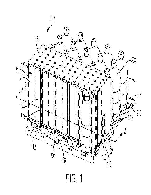
[0023] FIG. 1 shows a perspective view of product release mechanisms
according to an
embodiment.
[0024] FIGS. 2A and 2B show perspective cross-sectional views of the
product release
mechanisms of FIG. 1 as taken along line 2-2 in FIG. 1 showing gates in
different
positions.
[0025] FIG. 3 shows a bottom perspective view of the product release
mechanisms of
FIG. 1.
[0026] FIG. 4 shows a bottom perspective view of product release
mechanisms according
to an embodiment.
[0027] FIG. 5 shows a perspective view of product release mechanisms
having a gate
according to an embodiment.
[0028] FIG. 6 shows a perspective view of product release mechanisms
having a gate
according to an embodiment.
[0029] FIG. 7 shows a top-down view of product release mechanisms
having a gate
according to an embodiment.
CA 03206698 2023- 7- 27
WO 2022/169610
PCT/US2022/013154
- 5 -
[0030] FIG. 8 shows a top-down view of product release mechanisms
having a gate
according to an embodiment.
[0031] FIG. 9 shows a perspective view of a vending machine having
product release
mechanisms according to an embodiment.
[0032] FIG. 10 shows a top-down view of the product release
mechanism of FIG. 9.
[0033] FIG. 11 shows a perspective view of product release mechanisms
having a gate
according to an embodiment.
[0034] FIG. 12 shows a cross-sectional view of the product release
mechanism of FIG. 11
as taken along lines 12-12 in FIG. 11.
[0035] FIG. 13 shows a perspective view of a vending machine according
to an
embodiment.
[0036] FIG. 14 shows a cross sectional view of the vending machine of
FIG. 13 as taken
along lines 14-14 in FIG. 13.
[0037] FIGS. 15A and 15B show cross sectional views of a vending
machine having
gates according to an embodiment.
[0038] FIG. 16A shows a perspective view of a vending machine having a
delivery bin
according to an embodiment.
[0039] FIG. 16B shows a cross sectional view of the vending machine of
FIG. 16A taken
along lines 16B-16B in FIG. 16A.
[0040] FIG. 17 shows a close-up perspective view of a platform having a
sensor
according to an embodiment.
[0041] FIG. 18 shows a diagrammatic view of a vending machine having a
distance
sensor according to an embodiment.
[0042] FIG. 19 shows an exemplary method of determining removal of
products from a
vending machine according to an embodiment.
[0043] FIG. 20 shows a perspective view of a vending machine having a
delivery
mechanism according to an embodiment.
[0044] FIG. 21 shows a perspective view of a vending machine having a
delivery
mechanism according to an embodiment.
[0045] FIG. 22 shows a perspective view of a vending machine having
delivery bins
according to an embodiment.
CA 03206698 2023- 7- 27
WO 2022/169610
PCT/US2022/013154
- 6 -
[0046] FIG. 23 shows a longitudinal cross sectional view of the vending
machine of FIG.
22 as taken along line 23-23 in FIG. 22
[0047] FIG. 24 shows a perspective view of a vending machine having
delivery bins
according to an embodiment.
[0048] FIG. 25 shows a longitudinal cross sectional view of the vending
machine of FIG.
24 as taken along line 25-25 in FIG. 24.
[0049] FIG. 26 shows a longitudinal cross sectional view of a
vending machine having a
buffering mechanism that includes pads according to an embodiment.
[0050] FIG. 27 shows a longitudinal cross sectional view of a
vending machine having a
buffering mechanism that includes a flap according to an embodiment.
[0051] FIG. 28 shows a longitudinal cross sectional view of a vending
machine having a
buffering mechanism that includes a receiver according to an embodiment.
[0052] FIG. 29 shows a perspective view of a vending machine
having a buffering
mechanism that includes a Y-mechanism according to an embodiment
[0053] FIG. 30 shows an exploded view of a vending machine
having a buffering
mechanism that includes guide channels according to an embodiment.
[0054] FIG. 31 shows a front perspective view of a vending machine
having a buffering
mechanism that includes bristles according to an embodiment.
[0055] FIG. 32 shows a longitudinal cross sectional view of the vending
machine of FIG.
31 as taken along line 32-32 in FIG. 31.
[0056] FIG. 33 shows a longitudinal cross sectional view of a vending
machine having a
buffering mechanism that includes a constriction and additionally a cushion
according to
an embodiment.
DETAILED DESCRIPTION
[0057] Reference will now be made in detail to representative
embodiments illustrated in
the accompanying drawings. It should be understood that the following
descriptions are
not intended to limit the embodiments to one preferred embodiment. To the
contrary, it is
intended to cover alternatives, modifications, and equivalents as can be
included within
the spirit and scope of the described embodiments as defined by the claims.
[0058] Vending machines may include a product release mechanisms for
releasing a
product from a product storage area. When a consumer selects a product, such
as by a
CA 03206698 2023- 7- 27
WO 2022/169610
PCT/US2022/013154
- 7 -
user interface, the product release mechanism may release a product from the
product
storage area to be dispensed to a consumer, If the product release mechanism
fails to
function properly, the consumer's product may not be dispensed. As a result
the
consumer may have a negative experience and may not use the vending machine
again in
the future. If the release mechanisms releases more than the purchased number
of
products, the vending machine operator may lose money. Further, a
malfunctioning
product release mechanism may require repair, preventing the vending machine
from
being used until the repair is completed.
[0059] Some vending machines may provide consumers with access to the
product
compartment so that the consumers may hand select a product. However, it may
be
desirable to limit the consumer' s access to products within the storage
compartment to
prevent theft or tampering. In such vending machines, it may be desirable to
provide a
product release mechanism that allows for access to a single product while
limiting access
to additional products.
[0060] In vending machines having closed doors, and thus that are not
accessible by
consumers, the vending machine may allow a product to simply fall from a shelf
under
the force of gravity to a dispensing bin or portal. However, dropping a
product under the
force of gravity may result in damage to products, such as fragile or
breakable products,
such as chips or crackers, or may result in an increase in pressure in
carbonated
beverages. As a result, the carbonated beverage may overflow when opened or
the
consumer may have to wait to consume the beverage to allow the pressure to
dissipate,
which can be undesirable. Accordingly, mechanisms for controlling a drop of
the product
in a vending machine are desired.
[0061] Some vending machines may include separate delivery mechanisms
for conveying
the product released from the shelf to a delivery bin or portal. Delivery
mechanisms may
add expense to the capital costs of manufacturing the vending machine, and may
provide
another source of potential malfunction. Thus, it is desired to provide a
delivery
mechanism that is simple and that may reliably convey a product to a delivery
bin or
portal.
[0062] Some embodiments described herein relate to a product release
mechanism for a
vending machine that includes a first gate for releasing a product from a
platform and a
second gate for preventing access to additional products on the platform in
order to
CA 03206698 2023- 7- 27
WO 2022/169610
PCT/US2022/013154
- 8 -
provide a consumer with access to a purchased product while limiting the
consumer's
access the additional products on the platform. Some embodiments described
herein relate
to delivery mechanisms for conveying products to a delivery bin or portal in a
simple and
reliable manner. Some embodiments described herein relate to buffering
mechanisms for
vending machines that may control the gravitational drop of a product released
from a
shelf or platform in order to prevent or minimize damage to the dispensed
product.
[0063] As used herein, the term "product" may refer to any of various
items, including
but not limited to snacks, such as bags or boxes of chips, pretzels, crackers,
cookies,
granola bars, energy bars; packaged beverages such as beverages contained in
bottles,
cans, cartons, or pouches, such as water, sparkling water, carbonated soft
drinks, energy
drinks, coffee- or tea-based beverages, dairy-based beverages, or sports
drinks, among
others; and retail merchandise, such as small electronics, among others.
[0064] Product release mechanisms as described herein may be used in
vending machines
that provide consumers with direct access to the product compartment, such as
for hand
selecting a product, which may be referred to as "open door vending machines."
Product
release mechanisms described herein may also be incorporated into vending
machines
that do not provide consumers with direct access to the product compartment,
which may
be referred to as "closed door vending machines."
[0065] Some embodiments described herein relate to a product release
mechanism 100
for a vending machine. As shown in FIG. 1, each row of products may include a
product
release mechanism 100 for controlling release of products in that row. Each
product
release mechanism 100 may include a platform 110 having a first end 112
opposite a
second end 114. In some embodiments, a plurality of product release mechanisms
100
may be arranged in a side-by-side manner so as to form a shelf_ Products 500
may be
arranged in a single row from first end 112 to second end 114 of platform 110.
For
example, products 500 may be beverage containers arranged in an upright
orientation in a
single row. Platform 110 may include a rail 111, 113 on each side of platform
110 that
extends from first end 112 to or toward second end 114 of platform 110. Rails
111, 113
may help to maintain products in a row on platform 110 and gates of product
release
mechanism may be secured to a rail 111, 113 as discussed herein.
[0066] Products may be automatically advanced toward first end 112 of
platform 110,
such as by gravity or by an advancing mechanism 210. In this way, once a
product is
CA 03206698 2023- 7- 27
WO 2022/169610
PCT/US2022/013154
- 9 -
removed from first end 112 of platform 110, the remaining products may be
automatically
advanced toward first end 112 of platform 110 by gravity or by advancing
mechanism
210. For example, platform 110 may be arranged at an angle relative to a
horizontal
plane, such that second end 114 is arranged at a greater elevation than first
end 112 of
platform 110 so that products advance from second end 114 toward first end 112
under
the force of gravity. In such embodiments, as shown in FIG. 1, platform 110
may include
an advancing mechanism 210 formed as rollers 212 or bearings to facilitate
movement of
products toward first end 112 under the force of gravity. In some embodiments,
a pusher,
such as pusher 220 may be arranged at second end 114 of platform 110 and may
be
biased toward first end 112 (see, e.g., FIG. 18). When a product is removed,
the pusher
may automatically move the remaining products toward first end 112. The pusher
may be
spring-biased, driven by a motor, or the like. In another example, platform
110 may
include a conveyor assembly for automatically advancing products toward first
end 112.
Various advancing mechanisms are known as will be appreciated by one of
ordinary skill
in the art.
[0067] In some embodiments, a first gate 120 may be arranged at first
end 112 of
platform 110, and a second gate 150 may be spaced from first gate 120 at a
position
between first end 112 and second end 114 of platform 110, as best shown in
FIGS. 2A
and 2B. In operation, first gate 120 may remain in a closed position until a
product is
dispensed, and second gate 150 may remain in an open position to allow
products to
move along platform 110, as shown in FIG. 2A. When dispensing a product, first
gate
120 may open to allow the consumer to access a first product, while second
gate 150 may
move to a closed position to prevent consumer from retrieving any additional
products, as
shown in FIG 2B As second gate 150 closes, second gate 150 may also help to
push first
product toward first end 112 of platform 110. After a consumer removes the
first product,
first gate 120 may return to the closed position to prevent the consumer from
accessing
products, and second gate 150 may return to the open position to allow a
second product
to advance toward first end 112 of platform 110.
[0068] In some embodiments, product release mechanism 100 may further
include a third
gate 160 rearward of second gate 150 that is arranged between second gate 150
and
second end 114 of platform 110, as best shown in FIGS. 2A and 2B. Third gate
160 may
be movable from an open position in which products may advance toward first
end 112 of
CA 03206698 2023- 7- 27
WO 2022/169610
PCT/US2022/013154
- 10 -
platform 110 to a closed position in which products on platform 110 are
prevented from
advancing toward first end 112 of platform 110. First and second gates 120,
150 may be
used to control access to products, whereas third gate 160 may control
advancing of
products. In operation, third gate 160 may remain in an open position (see,
e.g., FIG. 2A)
until a product is dispensed in order to allow products to move along platform
110. When
dispensing a product, third gate 160 may move to a closed position (see, e.g.,
FIG. 2B) to
prevent products from advancing toward first end 112, which may interfere with
operation of second gate 150.
[0069] In some embodiments, as shown in FIG. 1, platform 110 may
include a stopper
105 arranged at a first end 112 of platform 110. Stopper 105 may extend from
platform
110 in an upright orientation to prevent a product from moving beyond first
end 112 of
platform 110, and thus from falling off of platform 110. In some embodiments,
stopper
105 may include an extension 106 such that stopper 105 is arranged in front of
first end
112 of platform 110. In this way, a product may be released through first gate
120 onto
extension 106 and held in place by stopper 105 (see, e.g., FIG. 2B). This may
facilitate
retrieval of the product by the consumer, and closing of second gate 150
behind the
released product.
[0070] Product release mechanism 100 may include a gate control
mechanism 170
configured to control opening and closing of one or more of first, second, and
third gates
120, 150, 160, as shown for example in FIG. 3. In some embodiments, gate
control
mechanism 170 may include a rack and pinion wherein a rack 171 having a
plurality of
teeth 173 engages a pinion 174 connected to a gate. As rack 171 is moved
linearly, such
as in a longitudinal direction of platform 110 (e.g., a direction from first
end to second
end or from second end to first end), pinions 174 rotate which in turn causes
rotation or
opening and closing of the associated gate.
[0071] In some embodiments, rack 171 of gate control mechanism 170 may
be connected
to a linkage 176 rather than a pinion that controls opening and closing of a
gate, as shown
for example in FIG. 4. As rack 171 is moved linearly, the movement of rack 171
may
actuate the linkage 176 to cause opening and closing of the gate connected to
linkage 176,
such as gate 120 in FIG. 4. Rack 171 may be linearly actuated in forward and
backward
directions by a solenoid 178. Gate control mechanism 170 may be arranged on a
bottom
surface 119 of platform 110. In this way, gate control mechanism 170 has a
compact
CA 03206698 2023- 7- 27
WO 2022/169610
PCT/US2022/013154
- 11 -
configuration and is not readily visible to a consumer using vending machine
having
product release mechanism 100.
[0072] In some embodiments, a single gate control mechanism 170 may
control both first
and second gates 120, 150. Alternatively, first and second gates 120, 150 may
each have
their own gate control mechanism 170. Additionally, third gate 160 may be
controlled by
the same gate control mechanism 170 used to control one or both of first and
second gates
120, 150 or third gate 160 may have its own gate control mechanism 170.
[0073] First gate 120 of product release mechanism 100 may be have any
of various
shapes and configurations as described herein. First gate 120 may include one
or more
panels individually movable from a closed position to an open position. First
gate 120
may be movable from the closed position to the open position such as by
pivoting about a
hinge, rotating around an axis, or sliding along a track. First gate 120 may
include a
transparent material, an opaque material, or a combination thereof. First gate
120 may
have a height that is the same as or less than a height of the product. First
gate 120 may
be generally planar or may have a curvature, such as a convex curvature.
[0074] Second gate 150 may include a single panel or may include a pair
of panels 151,
152, as shown in FIG. 2A. In some embodiments, second gate 150 may be
pivotally
connected to a first rail 111 or a second rail 113 of product release
mechanism 100. In
embodiments having a pair of panels, first panel 151 may be pivotally
connected to first
rail 111 and a second panel 152 may be pivotally connected to second rail 113.
In some
embodiments, second gate 150 may be arranged in an opening formed in first
rail 111 or
second rail 113 in the open configuration (see, e.g., FIG. 2A). In this way,
second gate
150 forms a portion of the rail and does not interfere with advancement of
products along
platform 110 Second gate 150 may rotate to a closed position in which second
gate 150
is arranged transversely to platform 110 and rails 111, 113 (see, e.g., FIG.
2B). When
second gate 150 has a pair of panels 151, 152, the pair of panels may meet in
an end-to-
end manner in the closed position to block access to products rearward of
second gate
150.
[0075] Third gate 160 may include a pair of arms, with a first arm
connected to a first rail
111 and a second arm connected to a second rail 113. Arms 161, 162 may be
arranged in
a recess of the rail in the open position and may extend inward from rail 111,
113 in the
closed position. In the closed position, arms 161, 162 may extend at an angle
relative to
CA 03206698 2023- 7- 27
WO 2022/169610
PCT/US2022/013154
- 12 -
rails 111, 113 such as an angle of about 10 degrees to about 60 degrees. In
the closed
position, arms 161, 162 of third gate 160 may not meet so that an opening is
formed
between arms 161, 162.
[0076] In some embodiments, product release mechanism 100 may include
first gate 120
that includes a single panel 122 pivotable about a hinge 121 arranged at a
side of panel
122, as shown in FIG. 5. Hinge 121 may connected to a rail 111, 113 of
platform 110,
such that panel 122 rotates about a vertical axis Z defined by hinge 121.
Panel 122 may
be substantially planar and may have a rectangular shape. Panel 122 of first
gate 120 may
have a width that corresponds to a width of platform 110 so that panel 122
extends from
first rail 111 to second rail 113 in the closed position to block access to
product from first
end 112 of platform 110. Panel 122 of first gate 120 may have a height that is
the same as
or slightly greater than a height of the product. In this way, when first gate
120 is in the
closed position, first gate 120 may prevent consumers from accessing a product
to prevent
theft of products. In some embodiments, however, panel 122 may have a height
that is
less than a height of the product, such as a height of about 50% of a height
of the product,
as shown for example in FIG. 14. Panel 122 may be shorter than product 500 so
that first
gate 120 allows a portion of the product above or below first gate 120 to be
viewed by the
consumer. Panel 122 may be formed of an opaque material to obscure the view of
product
500. However, in some embodiments, first gate 120 may include transparent or
translucent materials so that products are visible and can be seen by
consumers through
first gate 120.
[0077] In some embodiments, product release mechanism 100 may include a
first gate
120 and a second gate 150, as shown in FIG. 6. First gate 120 may include a
single panel
125 similar to the embodiment of FIG 5, but panel 125 of first gate 120 may
have a
curvature. Panel 125 may have a hinge 121 along a side thereof that is
connected to a rail,
such as first rail 111. However, in alternate embodiments, panel 125 may
instead have a
hinge 121 on the opposing side that is connected to second rail 113. Panel 125
may have a
height that is about the same as or greater than a height of the product.
Panel 125 may
have a convex curvature, so as to match a curvature of a product, such as a
bottle or can.
However, in some embodiments, panel 125 may have a concave curvature or a wave-
like
curvature to provide visual interest. Panel 125 may extend from first rail 111
to second
rail 113 in the closed position in order to block access to product 500. Panel
125 may
CA 03206698 2023- 7- 27
WO 2022/169610
PCT/US2022/013154
- 13 -
include a solid or opaque material and may include a window 125A having a
transparent
material so that a portion of product is visible through window 125A.
[0078] In some embodiments, product release mechanism 100 may include a
first gate
120 having two panels 123, 124, as shown in FIG. 1. In such embodiments, a
first panel
123 may be rotatably coupled to a first rail 111 and a second panel 124 may be
rotatably
coupled to a second rail 113. In a closed position, first and second panels
123, 124 meet
in an end-to-end manner to form a barrier that blocks access to a product. In
an open
position, first and second panels 123, 124 may pivot about hinges to allow the
product to
be accessed. In some embodiments, first and second rails 111, 113 may have a
height that
is the same as or slightly greater than a height of the product, and a cover
115 may be
arranged at an upper end of rails 1 I I, 113 so as to form an enclosure around
a product or
products at or adjacent first end 112 of platform 110.
[0079] In some embodiments, product release mechanism 100 may include a
single gate
120 that provides access to a product and that also prevents access to
additional products,
as shown in FIG. 7. In some embodiments, gate 120 may include a first panel
126 and a
second panel 127 connected to and perpendicular to first panel 126. Thus, gate
120 may
have an L-shape. In a closed position, first panel 126 may be arranged
transversely to
platform 110 so as to block access to a product on platform 110, and second
panel 127
may extend rearwardly toward second end 114 of platform 110 and parallel to
first rail
111. To dispense a product, gate 120 may rotate toward first end 112 of
platform 110
such that second panel 127 helps to push product 500 toward first end 112 to
dispense the
product, and first panel 126 rotates outwardly to provide access to the
product. In the
open position, second panel 127 may be arranged transversely to platform 110
to block
access to additional products on platform 110 Gate 120 may rotate by about 90
degrees
from the closed position to the open position and vice versa. In such
embodiments,
product release mechanism 100 may include a third gate 160 for controlling
advance of
additional products as described above. Third gate 160 may be open when gate
120 is in
the closed position and may move to a closed position to prevent advance of
products
when gate 120 is in the open position. The use of a single gate 120 to release
a product
and prevent access to additional products may simplify construction and
operation of
product release mechanism 100. Gates 120, 160 may be controlled by a gate
control
mechanism 170 as described above.
CA 03206698 2023- 7- 27
WO 2022/169610
PCT/US2022/013154
- 14 -
[0080] In some embodiments, gate 120 may include a pair of L-shaped
panels with a first
L-shaped panel pivotably connected to a first rail 111 and a second L-shaped
panel
pivotably connected to the opposing second rail 113, similar to first gate 120
of FIG. 1
but having a pair of L-shaped panels.
[0081] In some embodiments, product release mechanism 100 may include a
first gate
120 formed as a turnstile, as shown for example in FIG. 8. First gate 120 may
serve to
release a product while blocking access to additional products. First gate 120
may include
a central post 128 with a plurality of panels 129 extending therefrom. In FIG.
8, four
panels 129 extend from central post 128 so as to form an X- or plus-sign-
shape. When
first gate 120 has four panels 129, first gate 120 defines four product areas.
In some
embodiments, first gate 120 may be used to release products from two platforms
110 and
two rows of products, as shown in FIG. 8. As products advance toward first end
112 of
platform 110, products enter rear product areas defined by first gate 120,
wherein the rear
product areas are not accessible by consumers. As first gate 120 rotates about
central post
128 the products are advanced to forward areas of first gate 120 that are
accessible by the
consumer. To release a product, first gate 120 may rotate by a fixed number of
degrees,
e.g., 90 degrees. In such embodiments, product release mechanism 100 may
include a
third gate 160 for controlling advancement of products toward first gate 120
as described
above.
[0082] In some embodiments, product release mechanism 100 may include a
single gate
formed by a pair of curved panels 133, 134, as shown in FIGS. 9 and 10. Curved
panels
133, 134 may each be formed as an arc of a circle. Curved panels 133, 134 may
be
configured to rotate along a circular path at a first end 112 of platform 110.
First and
second curved panels 133, 134 may be arranged side-by-side in front of product
500 in
the closed position to form a barrier that blocks access to product. Product
release
mechanism 100 may include a third gate 160 arranged rearward of first gate 120
that
controls advancing of products along platform 110 as described above.
[0083] First and second curved panels 133, 134 may rotate about a
central axis Z, as
shown in FIG. 10. In order to move from closed position to open position, a
first curved
panel 133 may rotate in a clockwise direction, while a second curved panel 134
may
rotate in an opposing, counterclockwise direction such that first and second
curved panels
133, 134 meet in a side-by-side manner at a location behind or rearward of a
first product
CA 03206698 2023- 7- 27
WO 2022/169610
PCT/US2022/013154
- 15 -
500A to allow a consumer to access the first product 500A while blocking
access to a
second product 500B (and any additional products). In some embodiments, gate
120 may
instead include a single C-shaped panel that may be arranged in front of a
product in the
closed position to block access to all products, and may rotate approximately
180 degrees
in a clockwise or counterclockwise direction to a position behind the product
to provide
access to a single product while preventing access to additional products.
[0084] In some embodiments, product release mechanism 100 may include a
gate 120
configured to provide access to a product and also to prevent access to
additional
products, as shown in FIGS. 11 and 12. Gate 120 may include a panel 135
configured to
pivot or tilt outwardly along a horizontal axis Y. In some embodiments, panel
135 may
include arms 136 that slide along slots 116 defined by first and second rails
111, 113.
Panel 135 may have a hinge 137 along a bottom edge of panel 135 that is
connected to
first end 112 of platform 1 1 0 to allow panel 135 to tilt outwardly. In this
way, panel 135
may rotate about horizontal axis Y defined by hinge 137. In a closed position,
panel 135
may be arranged perpendicular to platform 110 in a vertical orientation to
block access to
products on platform 110. In an open position, panel 135 may rotate or tilt
outwardly to
provide access to a frontmost product on platform 110. In some embodiments,
gate 120
may be spring-biased so as to be biased in the closed configuration.
[0085] In some embodiments, gate 120 may include a base 139 on which
product rests, as
best shown in FIG. 12. Base 139 may be parallel to or flush with platform 110
when gate
120 is in the closed position such that a product may advance from platform
110 onto
base 139. When gate 120 is moved to the open position, product resting on base
139 tilts
forward for retrieval by the consumer. Base 139 may further include a flange
140 at a rear
end opposite panel 135 that extends above a plane of platform 110 to prevent
additional
products from advancing forward when gate 120 is open. In some embodiments,
panel
135 may include a handle 138 to allow the consumer to more easily rotate and
open gate
120.
[0086] In some embodiments, first and second rails may have a height
that is the same as
or greater than a height of products, and a cover 115 may be arranged at upper
end of rails
to form an enclosure around product at first end 112 of platform 110. This may
help to
further limit access to and theft of products.
CA 03206698 2023- 7- 27
WO 2022/169610
PCT/US2022/013154
- 16 -
100871 Any of the various product release mechanisms 100 described
herein may be
arranged in a product compartment of a vending machine for releasing and
products from
a platform or for controlling access to products. Product release mechanisms
100 may be
incorporated into a newly constructed vending machine, or may be retrofitted
into an
existing vending machine. For example, gates of product release mechanisms 100
may be
arranged on a shelf of the existing vending machine and gate control mechanism
may be
arranged on a lower surface of the shelf of the vending machine. In newly
constructed
vending machines, gates and gate control mechanism may be pre-assembled on a
platform or shelf.
[0088] The vending machine may include a user interface for receiving a
payment,
receiving a user selection of a product, or both. Product release mechanism
may be
actuated to release a product corresponding to the user selection. In some
embodiments,
user interface may include a touch screen display, a keypad, or a plurality of
actuators,
e.g., buttons, levers, switches, each corresponding to a single product
release mechanism.
In some embodiments, vending machine may be configured to communicate
wirelessly
with a mobile electronic device of a consumer, such as a smartphone, or may
include a
reader or scanner to read a barcode displayed by the consumer, such as by
displaying a
QR code on a smartphone of the consumer, wherein the QR code may encode a
product
selection, a payment method, or both. The user interface may be arranged on an
exterior
of vending machine or may be accessed once door of vending machine is opened.
In some
embodiments, the actuator may mechanically control actuation of a gate control
mechanism.
[0089] In an exemplary method of operation, a vending machine may
receive payment
from a consumer. Payment may be received via a user interface of the vending
machine,
such as by receipt of paper money, reading a payment card, scanning a barcode,
such as a
QR code, or by wireless communication, among other payment methods. When
payment
is received, a gate control mechanism of a product release mechanism of
vending
machine may release a product for access by consumer while restricting access
to
additional products. In some embodiments, each product release mechanism may
include
an indicator light, such as an LED light, that may blink or illuminate to
indicate to the
consumer that a gate is opened or unlocked for access by the consumer. In some
embodiments, the gate may remain open only for a predetermined period of time
and may
CA 03206698 2023- 7- 27
WO 2022/169610
PCT/US2022/013154
- 17 -
automatically close or lock upon expiration of the predetermined period of
time. In some
embodiments, a gate may remain open or unlocked until a product is removed, as
may be
detected by a product removal sensor, and upon removal of the product, the
gate may
close or lock.
[0090] Some embodiments described herein relate to a vending machine
300 having a
delivery mechanism, as shown for example in FIG. 13. Vending machine 300 may
include a housing 310 defining a product compartment 320, and a door 330
movably
connected to housing 310 to selectively provide access to product compartment
320.
Product compartment 320 may not be fully accessible to consumer, and a product
compartment panel 322 may at least partially cover product compartment 320 to
prevent
access to product compartment 320. Product compartment panel 322 may extend
from a
first side 321 of product compartment 320 toward an opposing second side 323.
Product
compartment panel 322 may include a transparent material so that products
within
product compartment 320 are visible to consumers using vending machine 300 A
product
retrieval area 324 may not be covered by product compartment panel 322 to
provide a
consumer with limited access to product compartment 320.
[0091] Vending machine 300 may include a plurality of rows of products
and product
release mechanisms 100, as best shown in FIG. 14. Each product release
mechanism 100
may include a platform 110 having a first end 112 opposite a second end 114 as
described
above. A release gate 180 may be arranged at first end 112 of platform 110
that is
movable from an open position to a closed position. Release gate 180 may have
any of
the configurations described above for gate 120. As shown in FIG. 14, release
gate 180
includes a single panel 182 having a hinge on a side of panel 182 and
connected to a rail
of product release mechanism 100, similar to gate 120 of FIG 5. Release gate
180 has a
height that is less than a height of product 500 As product compartment 320 is
not
directly accessible by consumers, gate 180 need not fully cover product to
prevent theft or
tampering, as product compartment panel 322 prevents access to products in
product
compartment 320. Vending machine 300 may include a user interface with a
plurality of
actuators 390 to be operated by a consumer to initiate dispensing of a
product, and each
actuator 390 may correspond to a specific release gate 180.
[0092] A delivery mechanism 380 may be arranged at first end 112 of
platforms 110
within product compartment 320 and may be arranged transversely to platforms
110 so as
CA 03206698 2023- 7- 27
WO 2022/169610
PCT/US2022/013154
- 18 -
to extend between a first side 321 and opposing second side 323 (e.g., right
and left side)
of product compartment 320 of vending machine 300. Delivery mechanism 380 may
convey a product released from a platform 110 to product retrieval area 324. A
dispensing
gate 190 may be arranged at product retrieval area 324 that is movable from a
closed
position in which product retrieval area 324 is inaccessible to an open
position in which
product retrieval area 324 is accessible to the consumer.
[0093] Delivery mechanism 380 may include a conveyor assembly that
includes a
conveyor belt 382 that forms a continuous loop around one or more rollers 384.
At least
one of the rollers 384 may be driven by a motor 386 so as to cause rotation of
the
conveyor belt 382. In operation, a product may be released by product release
mechanism
100 by opening release gate 180 so that product is released from platform 110
onto
conveyor belt 382. Conveyor belt 382 may convey product to product retrieval
area 324.
The consumer may manually move dispensing gate 190 from the closed position to
the
open position to access the product in the product retrieval area 324.
[0094] In some embodiments, dispensing gate 190 may include a central
hinge 193 and a
first panel 192 arranged opposite a second panel 194, such that dispensing
gate 190 has a
planar configuration. In a closed position, first panel 192 blocks product
retrieval area
324 and spans a distance from product compartment panel 322 to second side 323
of
product compartment 320, and second panel 194 is arranged generally parallel
to product
compartment panel 322 inside of product compartment 320. Dispensing gate 190
may
rotate approximately 90 degrees about central hinge 193 so that first panel
192 is
perpendicular to product compartment panel 322 to provide access to product
retrieval
area 324, and second panel 194 may be arranged transversely to conveyor belt
382 to
prevent the user from reaching into product compartment 320 when dispensing
gate 190
is in the open configuration.
[0095] In some embodiments, vending machine 300 may include a release
gate 180 and
dispensing gate 190 having alternate configurations, as shown in FIGS. 15A and
15B. For
example, release gate 180 may include a panel having a hinge along a bottom
edge of
panel and connected to platform 110. Dispensing gate 190 may include a pair of
curved
panels 196, 197 configured to rotate about a central axis, as described above
with respect
to FIGS. 9 and 10. Thus, dispensing gate 190 may include a first curved panel
196 and a
second curved panel 197 that may rotate from a closed position to an open
position. In the
CA 03206698 2023- 7- 27
WO 2022/169610
PCT/US2022/013154
- 19 -
closed position, first and second curved panels 196, 197 are arranged side by
side in front
of product retrieval area 324 to block access to a product. First and second
curved panels
196, 197 rotate in opposing directions to move to the open position in which
curved
panels 196, 197 are arranged side-by-side behind the product. In the closed
position,
curved panels 196, 197 may also block access to product compartment 320, as
shown in
FIG. 15B.
[0096] In some embodiments, vending machine 300 may include one or more
delivery
bins 350 for providing a consumer with access to a dispensed product, as shown
for
example in FIGS. 16A and 16B. Vending machine 300 may include a housing 310
defining a product compartment 320 for storing products and a door 330 movably
connected to housing 310 for providing access to delivery bins 350. Product
compartment
320 may include a plurality of product release mechanisms 100 arranged at
different
elevations. A delivery bin 350 may be arranged at a front end 112 of one or
more of the
product release mechanisms 100 so that a product released from a platform 110
may fall
under a force of gravity into delivery bin 350. A product compartment panel
322 may
cover product compartment 320 to prevent a consumer form accessing products in
product compartment 320. Consumer may thus have access only to delivery bin
350.
[0097] Delivery bin 350 may extend from first side 321 to an opposing
second side 323
of product compartment 320 so as to receive a product from any of various
product
release mechanisms 100. Delivery bin 350 may include a body 351 having an open
upper
end 352, with the upper end 352 at or below a level of front end 112 of
platform 110 such
that a product may fall into delivery bin 350 through open upper end 352.
Delivery bin
360 may include an open front wall 354 to provide a consumer with access to
the product
in delivery bin 350 Delivery bin 350 may include one or more flaps 355 movably
connected to body 351 of delivery bin 350 and movable from an open position to
a closed
position. Flaps 355 may be biased in the closed configuration (shown in dotted
lines in
FIG. 16B) so that upper end 352 is closed, and may open to allow a product to
pass
therethrough. Flap 355 may help to break the fall of the product into delivery
bin 350 to
minimize damage or shaking of the product, and may also prevent a consumer
from
reaching into product compartment 320 through delivery bin 350.
[0098] Some embodiments described herein relate to a vending machine
having a sensor
for detecting removal of a product from the product compartment, as shown in
FIGS. 17
CA 03206698 2023- 7- 27
WO 2022/169610
PCT/US2022/013154
- 20 -
and 18. Sensors may be used to detect removal of products to track product
inventory and
prevent theft of products. Information from sensors regarding the number of
products
removed may be used to update the vending machine inventory, to determine when
restocking is needed, and to determine the total price to charge a consumer.
[0099] In such embodiments, vending machine 300 may include a housing
310 defining a
product compartment 320 and a door 330 movably secured to housing 310. Product
compartment 320 may include a platform 110 on which products are arranged from
a first
end 112 to an opposing rear end. Each platform 110 may include an advancing
mechanism, such as a pusher, roller, or gravity feed. Further, each platform
110 may
include a stopper 105 at first end 112 of platform 110 to prevent products
from advancing
off of platform 110. The consumer may manually retrieve the desired products
when the
door 330 of vending machine 300 is opened. Product compartment 320 may include
a
sensor configured to detect a product removed from platform 110. In this way,
vending
machine 300 may automatically track removal of products without concern of
theft of
products.
[0100] In some embodiments, sensor 199 may be arranged on platform 110
at a first end
112 of platform 110, as shown in FIG. 17. Product sensor 199 may be an
infrared sensor,
or a photosensor, among others. A product 500 at first end 112 of platform 110
may rest
on product sensor 199, and product sensor 199 may detect when a product 500 is
removed
from the position on top of product sensor 199 to determine product removal.
As products
are automatically advanced from second end of platform 110 toward first end
112, a
second product on platform 110 may move into position on top of product sensor
199
when a first product is removed.
[0101] In some embodiments, sensor 199 may be a distance sensor
arranged at a second
end 114 of each platform 110, as shown in FIG. 18. Distance sensor 199 may be
arranged,
for example, on an interior wall of product compartment 320 at second end 114
of
platform 110. As a product is removed from a row of products on platform 110,
the
remaining products are advanced toward first end 112 of platform 110. Distance
sensor
199 may detect the distance D of the advancing mechanism, such as a pusher
220, to
distance sensor 199. In embodiments not having a pusher, distance sensor 199
may detect
the distance of the rearmost product to distance sensor 199. When a product is
removed,
the remaining products advance toward first end 112 of platform 110,
increasing the
CA 03206698 2023- 7- 27
WO 2022/169610
PCT/US2022/013154
-21 -
distance D. The change in distance D may be used to determine the number of
products
removed. When distance D is equal to a predetermined maximum distance, such as
a
distance at which pusher 220 is at the first end 112 of platform 110 and no
products
remain, vending machine 300 may send a signal to an operator to indicate that
restocking
is needed.
[0102] In some embodiments, an advancing mechanism 210 for
automatically advancing
products towards first end 112 of platform 110 may include a one-way advancing
assembly that may move in a direction toward first end 112 of platform 110 but
may not
move in a direction toward second end 114 of platform 110. One-way advancing
assembly may help to avoid interference with operation of sensors 199 and
inaccurate
product recognition, such as if a consumer attempts to return a product
removed from
platform 110.
[0103] An exemplary method of detecting removal of a product from a
vending machine
is shown in FIG. 19. The method may include detecting a first distance from a
distance
sensor to a product in a row of products 610. A second distance from the
distance sensor
to the product in the row of products may be detected after a consumer removes
one or
more products 620. A difference between the second distance and the first
distance may
be determined 630. A number of products removed may be determined based on the
difference between the first distance and the second distance 640. A consumer
may be
charged for the products removed based on the determination of the number of
products
removed 650. An inventory may be updated based on the number of products
removed
660.
[0104] Some embodiments described herein relate to closed door vending
machines 400
that include product compartments that are not directly accessible by a
consumer. In FIG
20, vending machine 400 includes a housing 410 defining a product compartment
420.
Product compartment 420 is inaccessible to consumers using vending machine
400. Front
wall 412 of housing 410 may include a transparent panel 414 to allow consumers
to view
product compartment 420 and products contained therein. Vending machine 400
may
further include one or more product delivery bins or portals 440 for providing
access to a
dispensed product.
[0105] Products may be arranged on a platform of a product release
mechanism 100 as
described herein. In some embodiments, a plurality of product release
mechanisms 100
CA 03206698 2023- 7- 27
WO 2022/169610
PCT/US2022/013154
-22 -
are arranged within product compartment 420, such as on a shelf A delivery
mechanism
480 may be extend along first ends 112 of a plurality of platforms 110 and may
extend
from a first side 421 to an opposing second side 423 of product compartment
420. In FIG.
20, delivery mechanism 480 includes a conveyor assembly, as descried above
with
respect to FIG. 13. Rather than conveying a product to a product retrieval
area 324 having
a dispensing gate 190 as in FIG. 13, delivery mechanism 480 may convey the
product to a
delivery portal 440 arranged on housing 410 of vending machine 400. Delivery
portal 440
may include a door 442 movably covering delivery portal 440 to provide a
consumer with
access to product within delivery portal 440.
[0106] In some embodiments, delivery mechanism 480 may include a sloped
surface 490
that directs a product toward a delivery portal 440, as shown in FIG. 21.
Delivery portal
440 may be arranged on a side of housing 410. Sloped surface 490 may be
arranged at an
angle relative to a transverse plane, such as an angle of about 5 degrees to
about 45
degrees, such that sloped surface 490 has a higher elevation at second side
423 than at
first side 421 of product compartment 420. Sloped surface 490 may be planar to
allow a
product to move under the force of gravity along the sloped surface 490 to
delivery portal
440. In some embodiments, sloped surface 490 may include rollers or bearings
to
facilitate movement of product toward delivery portal 440. Sloped surface 490
may
include a sidewall 492 to prevent product from falling off of a side of the
sloped surface
490. Sidewall 492 may be transparent so that the product may be viewed by the
consumer
throughout the dispensing process. Sloped surface 490 may be inexpensive and
requires
little to no maintenance due to no electrical components or moving parts. In
some
embodiments, each shelf may include a delivery mechanism 480 configured to
convey a
product dispensed from that shelf into a delivery portal 440_
[0107] In some embodiments, vending machine 400 may include one or more
delivery
bins 450, as shown in FIG. 22. Thus, vending machine 400 may be similar to
vending
machine 300 of FIGS. 16A and 16B, except vending machine 400 does not include
an
openable door. Vending machine 400 includes a housing 410 defining a product
compartment 420 for storing products. Housing 410 includes a front wall 412
having a
transparent panel 414 configured to allow a consumer to view product
compartment 420
of vending machine 400. Products may be stored in product compartment 420 on a
shelf
or platform. A product release mechanism 100 as described herein may be
arranged in
CA 03206698 2023- 7- 27
WO 2022/169610
PCT/US2022/013154
- 23 -
product compartment 420 so as to selectively control release of a product from
a platform
110 to a delivery bin 450 for access by a consumer. Product release mechanism
100 may
include a platform 110 having a first end 112 opposite a second end 114, and a
gate
arranged at first end 112 configured to move from a closed configuration in
which
products are retained on platform 110 to an open position in which a product
may fall off
of first end 112 of platform 110. Products may advance along platform 110 of
product
release mechanism 100 under a force of gravity due to an incline of platform
110 or
product release mechanism 100 may include an advancing assembly configured to
automatically advance products toward first end 112 of platform 110.
[0108] In some embodiments, delivery bin 450 may be arranged at first
end 112 of one or
more platforms 110 such that a product released from platform 110 may fall
under the
force of gravity into delivery bin 450. Delivery bin 450 may extend between
opposing
sides of product compartment 420 such that delivery bin 450 is configured to
receive a
product from any of various product release mechanisms 100. Delivery bin 450
may have
a body 451 defining an open upper end that is arranged at or below first end
112 of
platform 110 so that product may fall into delivery bin 450 via the open upper
end.
Delivery bin 450 may be arranged along front wall 412 of housing 410 of
vending
machine 400 and may be integrally formed with front wall 412. Front wall 412
may
define an opening 454 of delivery bin 450 through which a consumer may access
a
product in delivery bin 450.
[0109] In some embodiment, delivery bin 450 may include a flap 455
movably covering
opening 454, as shown in FIGS. 22 and 23. Flap 455 may be movably connected to
front
wall 412 or to body 451 of delivery bin 450. Flap 455 may rotate into delivery
bin 450
when a consumer retrieves a product such that flap 455 helps to prevent a
consumer from
reaching into product compartment 420. In some embodiments, each shelf of
vending
machine 400 may have an associated delivery bin 450, such that when a product
is
released from a shelf, the product falls into the delivery bin 450 for that
shelf In some
embodiments, one delivery bin 450 may be associated with two or more shelves
as shown
in FIGS. 22 and 23. For example, vending machine 400 may include four shelves,
and
two delivery bins 450. This may help to conserve space in product compartment
420
relative to a vending machine 400 having additional delivery bins 450 while
helping to
reduce a distance that each product falls to reach delivery bin 450. In some
embodiments,
CA 03206698 2023- 7- 27
WO 2022/169610
PCT/US2022/013154
-24 -
vending machine 400 may include a single delivery bin 450 arranged at a lower
end of
product compartment 420 to receive a product released from any shelf The use
of one
delivery bin 450 may reduce the cost of manufacturing vending machine 400 and
may
conserve space within product compartment 420.
[0110] In some embodiments, delivery bin 450 may include a drawer 458
as shown for
example in FIGS. 24 and 25. Rather than a flap 455 as shown in FIGS. 22 and
23, drawer
458 is movably connected to delivery bin 450 from a closed configuration in
which a
front wall 459 of drawer 458 is aligned with front wall 412 of housing 410,
and drawer
458 may pivot or rotate outwardly to provide a consumer with access to a
product held
within drawer 458. When drawer 458 is in the open configuration, a rear wall
457 of
drawer 458 may help to block the opening of front wall 412 of vending machine
400 to
prevent a consumer from accessing product compartment 420.
[0111] Some embodiments described herein relate to vending machine 400
having a
buffering mechanism 460 configured to control or slow a fall of a product in
vending
machine 400. Vending machine 400 may include one or more delivery bins 450 and
may
include a delivery bin 450 arranged at a lower end of product compartment 420.
Product
compartment 420 may include a plurality of product release mechanisms 100 as
described
herein, and may include a space between a first end 112 of platforms 110 of
product
release mechanisms 100 and front wall 412 of housing 410 to provide room for a
product
to fall to delivery bin 450. In this way, when a product is released from a
platform 110,
the product may fall under the force of gravity into delivery bin 450 and may
be retrieved
by a consumer through a front opening 454 of delivery bin 450. Products
falling from
platforms 110 that are located toward an upper end of product compartment 420
fall a
greater distance to reach delivery bin 450 and as a result may be damaged,
broken, or
shaken by the fall. In order to control the gravitational fall of the product,
and to reduce
the speed of the product, vending machine 400 may include one or more
buffering
mechanisms 460.
[0112] In some embodiments, as shown in FIG. 26, buffering mechanism
460 may
include one or more pads 462. Pad 462 may be configured to break the fall of
the product
toward delivery bin 450. Each pad 462 may be composed of a soft material, such
as a
foam or rubber to provide cushioning for the product as it falls. In some
embodiments,
each pad 462 may extend from a first side of product compartment 420 to or
toward an
CA 03206698 2023- 7- 27
WO 2022/169610
PCT/US2022/013154
- 25 -
opposing second side of product compartment in a transverse direction of
housing 410.
Pad 462 may have a semi-circular cross sectional area as shown for example in
FIG. 26.
However, in alternate embodiments, pad 462 may have alternate cross sectional
areas,
such as a triangular cross sectional area.
[0113] Pads 462 may be arranged at a first end 112 of platforms 110,
pads 462 may be
arranged on front wall 412 of housing 410, or both. In some embodiments,
buffering
mechanism 460 may include a plurality of pads 462 spaced from one another
between
upper end and lower end of product compartment 420. In such embodiments, pads
462
may alternate locations on front wall 412 and first end 112 of platforms 110,
as shown in
FIG. 26. This may help to ensure product contacts one or more pads 462 as it
falls.
[0114] In some embodiments, buffering mechanism 460 may include a flap
464 movable
from a closed position to an open position, as shown in FIG. 27. Flap 464 may
be
connected to a front wall 412 of housing 410 and may extend toward first end
112 of
platforms 110. In the closed position, flap 464 may be arranged along a
transverse axis X
of vending machine 400. Flap 464 may be biased in the closed position. Flap
464 may be
movable to an open position in which flap 464 is arranged generally parallel
to a plane of
front wall 412 of housing 410 and a closed position in which flap 464 is
transverse to a
plane of front wall 412 of cabinet. Flap 464 may be biased in the closed
position by a
biasing mechanism, such as a spring, among others. Flap 464 may include a
cushion or
pad to provide a soft landing for product as it contacts flap 464.
[0115] In some embodiments, buffering mechanism 460 may include a
pulley 466, as
shown for example in FIG. 28. A receiver 468 may be arranged in front of
platforms 110
so as to receive a product thereon. A cable 470 may be arranged around a
pulley 466 and
connected at a first end to receiver 468 and connected at a second end to a
counterweight
472. As product falls from a platform 110 onto receiver 468, receiver 468 may
lower the
product to the delivery bin 450 balanced by counterweight 472 to reduce the
speed at
which the product moves to delivery bin 450.
[0116] In some embodiments, buffering mechanism 460 may include a Y-
mechanism
474, as shown for example in FIG. 29. Y-mechanism 474 may include a receiver
476
movable along a tracks 478. Receiver 476 may have a V-shape to receive and
hold a
product. In some embodiments, receiver 476 may have a U-shape, among other
configurations. A pair of tracks 478 may be arranged on opposing sides 421,
423 of
CA 03206698 2023- 7- 27
WO 2022/169610
PCT/US2022/013154
- 26 -
product compartment 420 and may extend from lower end 425 toward upper end 427
of
product compartment 420. Opposing ends of receiver 476 may include pinions
that
engage with teeth of tracks 478. However, in some embodiments, receiver 476
may be
movable along tracks, or may be lifted by a pulley and cable system. Receiver
476 may
be automatically movable along tracks 478, such as by a motor. When a product
has been
selected for dispensing, Y-mechanism 474 may move receiver 476 to the location
of the
shelf containing the product to be dispensed so that the product falls a short
distance into
receiver 476. Y-mechanism 474 may then move receiver 476 containing the
dispensed
product to the delivery bin 450 for access by a consumer.
[0117] In some embodiments, buffering mechanism 460 may include guide
channels 480
defined by vertical walls 482, as shown in FIG. 30. A pair of vertical walls
482 may
define a channel 480 such that when a product is released from a product
release
mechanism 100, movement of product is constrained by channels 480. Channels
480 may
help to ensure products move only in a vertical direction and does not spin or
move
laterally across product compartment 420 when falling. In some embodiments,
channels
480 may have a width that is similar to a width of the product such that
channel 480
defines a narrow passage through which product travels which may result in
slowing the
fall of the product. Channels 480 may extend from upper end 427 of product
compartment 420 to or toward lower end 425. In some embodiments, a lower end
of each
wall 482 may have a bend or curvature and may include a cushion or pad.
[0118] In some embodiments, buffering mechanism 460 may include a
plurality of
bristles 484, as shown in FIGS. 31 and 32. Bristles 484 may extend from a
front wall 412
to or toward first end 112 of platforms 110. Bristles 484 may be flexible so
as to bend or
flex when contacted by a product In this way, as a product falls from a
platform 110
under the force of gravity toward delivery bin 450, bristles 484 may slow the
fall of the
product to prevent damage to the product or shaking of carbonated beverages.
In some
embodiments, vending machine 400 may include a combination of buffering
mechanisms
as described herein. For example, FIGS. 31 and 32 show a combination of guide
channels
480 and bristles 484. Bristles 484 may be secured to guide channels 480 and
may be
arranged at various locations within guide channels 480. Further, as shown in
FIG. 31,
channels may not extend entirely to lower end of product compartment 420.
Products on
platforms 110A adjacent lower end 425 may fall a shorter distance relative to
products on
CA 03206698 2023- 7- 27
WO 2022/169610
PCT/US2022/013154
- 27 -
upper platforms 110B and may not require buffering mechanisms 460 to break
their fall
due to the short distance traveled.
[0119] In some embodiments, buffering mechanism 460 may include a
constriction 486,
as shown in FIG. 33. Constriction 486 may be a narrow passageway configured to
slow a
fall of a product from a platform 110 to delivery bin 450. Constriction 486
may be
defined by one or more panels 488 extending from platforms 110 toward front
wall 412
of housing 410, or extending from front wall 412 of housing 410 toward
platforms 110.
As a product falls from a platform 110, product may fall freely until reaching
constriction
486 and may be deflected by panel 488 through constriction 486. In some
embodiments,
constriction 486 may be arranged at a lower end of a guide channel 480, such
that a
product falls through a guide channel 480 and is then deflected through
constriction 486
to control and slow a fall of a product toward delivery bin 450.
[0120] In some embodiments, vending machine 400 may include a cushion
494 arranged
in delivery bin 450, as shown in FIG. 33. Cushion 494 may soften the impact of
the
product with delivery bin 450 to minimize damage or breakage of a product.
Cushion 494
may include a soft material, such as a foam, among others, that may absorb the
impact of
the product.
[0121] Vending machine 400 may include a combination of buffering
mechanism 460 as
described herein. In some embodiments, vending machine 400 may include one or
more
of guide channels 480, a constriction 486, pads 462, flaps 464, bristles 484,
and a cushion
494.
[0122] In any of the various embodiments described herein, a vending
machine may
include a cooling unit configured to maintain the product compartment or a
portion
thereof at a predetermined temperature, such as may be necessary for providing
the stored
products at a desired temperature for consumption, for storing perishable
products, or for
extending shelf-life of the stored products. The cooling unit may be a vapor-
compression
refrigeration unit, a thermoelectric cooling unit, or a cold plate, among
other cooling
units. In some embodiments, a product compartment of the vending machine may
be
maintained at ambient temperature, such as when vending machine is used to
store retail
merchandise.
[0123] It is to be appreciated that the Detailed Description section,
and not the Summary
and Abstract sections, is intended to be used to interpret the claims. The
Summary and
CA 03206698 2023- 7- 27
WO 2022/169610
PCT/US2022/013154
- 28 -
Abstract sections may set forth one or more but not all exemplary embodiments
of the
present invention(s) as contemplated by the inventors, and thus, are not
intended to limit
the present invention(s) and the appended claims in any way.
[0124] The present invention has been described above with the aid of
functional building
blocks illustrating the implementation of specified functions and
relationships thereof.
The boundaries of these functional building blocks have been arbitrarily
defined herein
for the convenience of the description. Alternate boundaries can be defined so
long as the
specified functions and relationships thereof are appropriately performed.
[0125] The foregoing description of the specific embodiments will so
fully reveal the
general nature of the invention(s) that others can, by applying knowledge
within the skill
of the art, readily modify and/or adapt for various applications such specific
embodiments, without undue experimentation, and without departing from the
general
concept of the present invention(s). Therefore, such adaptations and
modifications are
intended to be within the meaning and range of equivalents of the disclosed
embodiments,
based on the teaching and guidance presented herein. It is to be understood
that the
phraseology or terminology herein is for the purpose of description and not of
limitation,
such that the terminology or phraseology of the present specification is to be
interpreted
by the skilled artisan in light of the teachings and guidance herein.
[0126] The breadth and scope of the present invention(s) should not be
limited by any of
the above-described exemplary embodiments, but should be defined only in
accordance
with the following claims and their equivalents.
CA 03206698 2023- 7- 27