Note: Descriptions are shown in the official language in which they were submitted.
CA 03206891 2023-06-27
WO 2022/150807 PCT/US2022/070020
TISSUE REMODELING SYSTEMS AND METHODS
BACKGROUND
Field
[0001] The present disclosure relates to systems and methods for
remodeling
tissue. In particular, the present disclosure relates to systems and methods
for heart valve
remodeling, such as mitral valve remodeling.
Description of Related Art
[0002] Heart valves lie at the exit of each of the four heart
chambers. Heart valves
work as one-way valves to prevent blood from flowing in the wrong direction.
Each valve has
a set of flaps, called leaflets or cusps. Valve regurgitation is when blood
leaks through an
incompletely closed valve, allowing blood flow in two directions during
contraction.
Regurgitation may be caused either due to an abnormality of the leaflets
themselves (called
primary regurgitation), such as valve prolapse, damaged chordae, rheumatic
fever,
endocarditis, trauma or congenital heart defects. On the other hand, in
secondary regurgitation,
the valve itself is intact and only the surrounding structures the valve
leaflets insert into are
abnormal, resulting in regurgitation. Examples for secondary regurgitation are
history of heart
attack, cardiomyopathy, prolong use of certain drugs, radiation, atrial
fibrillation, etc.
Regurgitation can result in congestive heart failure, which is the most common
hospital
admission diagnosis in the United States. Symptoms of congestive heart failure
include fatigue,
shortness of breath, swelling of feet and legs. Valve regurgitation leads to a
vicious cycle of
heart failure, arrhythmias, and worsening cardiomyopathy (weakening of the
heart muscle),
which results in more regurgitation.
[0003] Historically, open surgical valve repair or replacement is
performed to treat
diseases such as regurgitation. More recently, catheter-based technologies
have been
developed and introduced into clinical practice for the repair of the mitral
valve. In general,
repair is deemed superior to valve replacement to restore coaptation of the
leaflets.
-1-
CA 03206891 2023-06-27
WO 2022/150807 PCT/US2022/070020
SUMMARY
[0004] The systems, methods and devices described herein have
innovative
aspects, no single one of which is indispensable or solely responsible for
their desirable
attributes. Without limiting the scope of the claims, some of the advantageous
features will
now be summarized.
[0005] An aspect of the present disclosure involves a system for
mitral valve
remodeling that includes a first tissue anchor and a second tissue anchor. The
first tissue anchor
is configured to be implanted into tissue at a first location at or near an
annulus of a mitral
valve of a patient. The first tissue anchor comprises an anchor portion, a
drive portion and a
suture mount portion. The anchor portion engages the tissue and is implanted
by rotation about
a longitudinal axis of the first tissue anchor. The drive portion is rotatably
fixed with respect
to the anchor portion and is configured to removably engage with a drive
member of a catheter.
The suture mount portion is rotatable relative to the anchor portion and the
drive portion and
is located between the drive portion and the anchor portion along the
longitudinal axis. The
second tissue anchor is configured to be implanted into tissue at a second
location at or near
the annulus of the mitral valve across from the first location. The second
tissue anchor
comprises an anchor portion, a drive portion and a suture mount portion. The
anchor portion
engages the tissue and is implanted by rotation about a longitudinal axis of
the second tissue
anchor. The drive portion is rotatably fixed with respect to the anchor
portion and is configured
to removably engage with the drive member of the catheter. The suture mount
portion is
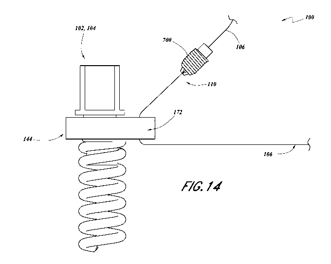
rotatable relative to the anchor portion and the drive portion and is located
between the drive
portion and the anchor portion along the longitudinal axis. A suture has a
tensioned portion
that extends between a first suture mount location on the suture mount portion
of the first tissue
anchor and a second suture mount location on the suture mount portion of the
second tissue
anchor. The suture mount portions of the first and second tissue anchors
rotate to align with
one another in response to tension applied to the suture.
[0006] In an embodiment, each of the first and second suture mount
locations of
the first and second tissue anchors comprises a passage that accommodates the
suture, wherein
the tensioned portion of the suture extends from an end of the passage
relatively closer to the
anchor portion.
-2-
CA 03206891 2023-06-27
WO 2022/150807 PCT/US2022/070020
[0007] In an embodiment, a suture lock is configured to secure a
portion of the
suture relative to the second tissue anchor to fix a length of a tensioned
portion of the suture
between the first tissue anchor and the second tissue anchor.
[0008] In an embodiment, the suture lock comprises a first portion and
a second
portion movable relative to the first portion, wherein a lock portion of the
suture is captured
between the first portion and the second portion.
[0009] In an embodiment, the first portion comprises a passage,
wherein the lock
portion of the suture passes through the passage.
[0010] In an embodiment, the first portion of the suture lock is
configured to
contact the suture mount portion of the second tissue anchor to fix the length
of the tensioned
portion of the suture.
[0011] In an embodiment, the passage of the suture lock is aligned
with a passage
of the second suture mount location of the second tissue anchor when the
suture lock is in
contact with the second tissue anchor.
[0012] In an embodiment, the first portion of the suture lock is
rotationally fixed
relative to the second portion.
[0013] In an embodiment, a threaded fastener is configured to move the
first
portion of the suture lock relative to the second portion.
[0014] In an embodiment, the threaded fastener is configured to move
the first
portion of the suture lock toward and away from the second portion.
[0015] In an embodiment, a suture cutter is configured to cut the
suture.
[0016] In an embodiment, the suture cutter comprises a tip having an
axial slot and
a radial passage, wherein the axial slot intersects the radial passage,
wherein the suture passes
through the radial passage, the suture cutter further comprising a blade that
is movable within
the slot to cut the suture.
[0017] In an embodiment, the anchor portion comprises one or more
barbs.
[0018] In an embodiment, each of the barbs comprises a tubular element
having an
angled end with a tip of the angled end located radially outward.
[0019] An aspect of the present disclosure involves a system for
implanting a tissue
anchor in heart tissue of a patient. The system includes a delivery catheter
comprising an
anchor delivery tip. The tip comprises a stationary portion and a rotatable
portion. The
-3-
CA 03206891 2023-06-27
WO 2022/150807 PCT/US2022/070020
stationary portion comprises a suture passage having a first end and a second
end. The rotatable
portion comprises a drive portion. The system further includes a tissue anchor
comprising an
anchor portion, a drive portion and a suture mount portion. The anchor portion
engages the
heart tissue and is implanted by rotation about a longitudinal axis of the
tissue anchor. The
drive portion is rotatably fixed with respect to the anchor portion and is
configured to
removably engage with the drive portion of the catheter. The suture mount
portion is rotatable
relative to the anchor portion and the drive portion. A suture is secured to
the suture mount
portion. The tissue anchor is configured to be engaged with the delivery
catheter with the drive
portion of the tissue anchor engaged with the drive portion of the delivery
catheter. The suture
extends through the suture passage of the tip of the delivery catheter such
that the suture can
be tensioned to restrain the suture mount portion of the tissue anchor from
rotating as the
rotatable portion of the tip of the delivery catheter is rotated to rotate the
drive portion and the
anchor portion of the tissue anchor to thereby implant the tissue anchor into
the heart tissue.
[0020] In an embodiment, the suture passage of the stationary portion
is located
radially outward of the rotatable portion.
[0021] In an embodiment, the suture mount portion is located between
the drive
portion and the anchor portion.
[0022] In an embodiment, the delivery catheter comprises a distal tip
cover
configured to surround the tissue anchor prior to deployment.
[0023] In an embodiment, the distal tip cover comprises a slot through
which the
suture passes from exterior the distal tip cover to interior the distal tip
cover such that the suture
can be secured to the suture mount portion.
[0024] In an embodiment, the distal tip cover comprises a slit that
extends from the
slot to a distal end of the distal tip cover, wherein the slit is configured
such that the suture can
move from the slot, pass through the slit, and be separated from the distal
tip cover when the
tissue anchor is deployed from the delivery catheter.
[0025] In an embodiment, the anchor portion comprises one or more
barbs.
[0026] In an embodiment, each of the barbs comprises a tubular element
having an
angled end with a tip of the angled end located radially outward.
[0027] An aspect of the present disclosure involves a tissue anchor
including an
anchor portion comprising a helical thread configured to be implanted into
bodily tissue by
-4-
CA 03206891 2023-06-27
WO 2022/150807 PCT/US2022/070020
rotation about a longitudinal axis of the tissue anchor. The tissue anchor
further includes a
drive portion that is rotatably fixed with respect to the anchor portion. The
drive portion is
configured to removably engage with a drive member of a catheter such that
rotation of the
drive member rotates the drive portion and the anchor portion of the tissue
anchor. The tissue
anchor further includes a suture mount portion is rotatable relative to the
anchor portion and
the drive portion. The suture mount portion is configured to connect to a
suture at a suture
mount location. The suture mount portion is configured to rotate to align the
suture mount
location with a direction of force of the suture. The suture mount portion is
located between
the drive portion and the anchor portion along the longitudinal axis.
[0028] In an embodiment, the helical thread of the anchor portion is a
helical coil
defining a hollow interior space.
[0029] In an embodiment, the helical coil comprises a circular cross-
sectional
shape.
[0030] In an embodiment, the drive portion defines a radially outward-
facing drive
surface that is configured to engage the drive member of the catheter.
[0031] In an embodiment, the drive portion comprises a square cross-
sectional
shape that defines the radially outward-facing drive surface.
[0032] In an embodiment, the suture mount portion has a peripheral
surface
surrounding the longitudinal axis of the tissue anchor, the peripheral surface
defining a
geometric center of the suture mount portion, wherein an axis of rotation of
the suture mount
portion is spaced from the geometric center.
[0033] In an embodiment, the suture mount location is on an opposite
side of the
geometric center from the axis of rotation.
[0034] In an embodiment, the suture mount location comprises a passage
extending
through the suture mount portion in a direction substantially aligned with the
longitudinal axis
of the tissue anchor.
[0035] In an embodiment, a length of the anchor portion along the
longitudinal axis
is greater than a length of one or both of the drive portion and the suture
mount portion.
[0036] In an embodiment, the length of the drive portion is greater
than the length
of the suture mount portion.
[0037] In an embodiment, the anchor portion comprises one or more
barbs.
-5-
CA 03206891 2023-06-27
WO 2022/150807 PCT/US2022/070020
[0038] In an embodiment, each of the barbs comprises a tubular element
having an
angled end with a tip of the angled end located radially outward.
[0039] An aspect of the present disclosure involves a tissue anchor
including an
anchor portion comprising a helical thread configured to be implanted into
bodily tissue by
rotation about a longitudinal axis of the tissue anchor. The tissue anchor
further includes a
drive portion that is rotatably fixed with respect to the anchor portion. The
drive portion is
configured to removably engage with a drive member of a catheter such that
rotation of the
drive member rotates the drive portion and the anchor portion of the tissue
anchor. The tissue
anchor further includes a suture mount portion that is rotatable relative to
the anchor portion
and the drive portion. The suture mount portion is configured to connect to a
suture at a suture
mount location. The suture mount portion is configured to rotate to align the
suture mount
location with a direction of force of the suture. The suture mount portion is
located above the
anchor portion along the longitudinal axis. The suture mount portion has a
first end surface
and a second end surface opposite the first end surface. The second end
surface is closer to the
anchor portion than the first end surface along the longitudinal axis. The
suture mount portion
is configured such that suture extends from the tissue anchor at or below the
second end
surface.
[0040] In an embodiment, the suture mount portion is located
immediately adjacent
the anchor portion.
[0041] In an embodiment, the helical thread of the anchor portion is a
helical coil
defining a hollow interior space.
[0042] In an embodiment, the helical coil comprises a circular cross-
sectional
shape.
[0043] In an embodiment, the drive portion defines a radially outward-
facing drive
surface that is configured to engage the drive member of the catheter.
[0044] In an embodiment, the drive portion comprises a square cross-
sectional
shape that defines the radially outward-facing drive surface.
[0045] In an embodiment, the suture mount portion has a peripheral
surface
surrounding the longitudinal axis of the tissue anchor, the peripheral surface
defining a
geometric center of the suture mount portion, wherein an axis of rotation of
the suture mount
portion is spaced from the geometric center.
-6-
CA 03206891 2023-06-27
WO 2022/150807 PCT/US2022/070020
[0046] In an embodiment, the suture mount location is on an opposite
side of the
geometric center from the axis of rotation.
[0047] In an embodiment, the suture mount location comprises a passage
extending
through the suture mount portion from the first end surface to the second end
surface in a
direction substantially aligned with the longitudinal axis of the tissue
anchor.
[0048] In an embodiment, a length of the anchor portion along the
longitudinal axis
is greater than a length of one or both of the drive portion and the suture
mount portion.
[0049] In an embodiment, the length of the drive portion is greater
than the length
of the suture mount portion.
[0050] In an embodiment, the anchor portion comprises one or more
barbs.
[0051] In an embodiment, each of the barbs comprises a tubular element
having an
angled end with a tip of the angled end located radially outward.
[0052] An aspect of the present disclosure involves a suture lock for
a tissue
remodeling system. The suture lock includes a first portion comprising a base
flange and a hub
extending in an axial direction from the base flange. The base flange
comprises a suture
passage configured to accommodate a suture of the tissue remodeling system.
The suture lock
also includes a second portion comprising an end wall and at least one side
wall defining a
space to slidably engage the hub of the first portion. The end wall and the at
least one side wall
are configured to prevent rotation of the first portion when the hub is
positioned within the
space. The second portion further comprising a clamping surface located
adjacent an end of
the suture passage of the base flange and configured to clamp a portion of the
suture against
the base flange to fix the suture relative to the suture lock. The second
portion is movable
toward and away from the first portion to selectively clamp and release the
suture.
[0053] In an embodiment, the at least one sidewall comprises a first
side wall and
a second side wall, wherein the first and second side walls are parallel and
spaced apart from
one another to receive the hub therebetween.
[0054] In an embodiment, the first portion comprises a threaded cavity
extending
in the axial direction within the hub and the second portion comprises an
opening within the
end wall, the suture lock further comprising a threaded fastener that passes
through the opening
and threadably engages the threaded cavity, wherein the threaded fastener is
configured to
move the first portion toward the second portion in response to rotation in a
first direction and
-7-
CA 03206891 2023-06-27
WO 2022/150807 PCT/US2022/070020
to allow the first portion to move away from the second portion in response to
rotation in a
second direction.
[0055] An aspect of the present disclosure involves a method of
remodeling a
mitral valve. The method includes implanting, using at least one catheter, a
first tissue anchor
at a first location at or near an annulus of a mitral valve of a patient. The
method further
includes implanting, using the at least one catheter, a second tissue anchor
at a second location
at or near the annulus of the mitral valve of the patient across from the
first location. The
method also includes extending a suture between the first tissue anchor and
the second tissue
anchor and using the suture to move the first tissue anchor and the second
tissue anchor toward
one another. The method includes fixing a tension length of the suture between
the first tissue
anchor and the second tissue anchor using a suture lock that is lockable using
the at least one
catheter. The method further includes observing the function of the mitral
valve and, if desired,
unlocking the suture lock, increasing or decreasing the tension length of the
suture, and
relocking the suture lock.
[0056] In an embodiment, the method further comprises cutting an
excess portion
of the suture using a suture cutter.
[0057] An aspect of the present disclosure involves a method of
tensioning a suture
of a mitral valve remodeling system. The method includes slidably engaging a
suture lock with
a suture that has an end fixed to a first tissue anchor implanted at a first
location at or near an
annulus of the mitral valve and is slidably engaged with a second tissue
anchor implanted at a
second location at or near the annulus of the mitral valve. The method further
includes sliding
the suture lock along the suture toward the second tissue anchor using a
catheter until the suture
lock contacts the second tissue anchor. The method also includes applying a
pulling force to
the suture while holding the suture lock in contact with the second tissue
anchor to tension a
portion of the suture extending between the first tissue anchor and the second
tissue anchor.
[0058] In an embodiment, the method further includes locking the
suture lock on
the suture to maintain the tension of the portion of the suture extending
between the first tissue
anchor and the second tissue anchor.
[0059] In an embodiment, the method further includes disengaging the
catheter
from the suture lock after the suture lock is locked on the suture.
-8-
CA 03206891 2023-06-27
WO 2022/150807 PCT/US2022/070020
[0060] An aspect of the present disclosure involves a tissue anchor
having an
anchor portion comprising a helical thread configured to be implanted into
bodily tissue by
rotation in a first direction about a longitudinal axis of the tissue anchor.
One or more barbs
are configured to permit rotation of the tissue anchor in the first direction
and inhibit rotation
of the tissue anchor in a second direction opposite the first direction. The
tissue anchor also
comprises a drive portion that is rotatably fixed with respect to the anchor
portion. The drive
portion is configured to removably engage with a drive member of a catheter
such that rotation
of the drive member rotates the drive portion and the anchor portion of the
tissue anchor. The
tissue anchor also comprises a suture mount portion configured to connect to a
suture at a
suture mount location.
[0061] In an embodiment, the suture mount portion is rotatable
relative to the
anchor portion and the drive portion.
[0062] In an embodiment, the suture mount portion is configured to
rotate to align
the suture mount location with a direction of force of the suture.
[0063] In an embodiment, the suture mount portion is located between
the drive
portion and the anchor portion along the longitudinal axis.
[0064] In an embodiment, the one or more barbs comprises a plurality
of barbs
spaced from one another along a length of the helical thread.
[0065] In an embodiment, each of the one or more barbs comprises an
angled end
having a tip that is located radially outward on the barb.
[0066] In an embodiment, the angled end has an angle between 30-60
degrees.
[0067] In an embodiment, each of the one or more barbs is or comprises
a tubular
element secured to the helical thread.
[0068] In an embodiment, the tubular element is straight.
[0069] In an embodiment, the tubular element defines an interior
passage having a
diameter that is larger than a diameter of the helical thread to allow the
tubular element to be
advanced along the helical thread during manufacture.
BRIEF DESCRIPTION OF THE DRAWINGS
[0070] Throughout the drawings, reference numbers can be reused to
indicate
general correspondence between reference elements. The drawings are provided
to illustrate
-9-
CA 03206891 2023-06-27
WO 2022/150807 PCT/US2022/070020
example embodiments described herein and are not intended to limit the scope
of the
disclosure.
[0071] Figure 1 is a perspective view of a mitral valve remodeling
system
implanted in a mitral valve of a patient.
[0072] Figure 2 is a perspective view of a tissue anchor of the system
of Figure 1.
[0073] Figure 2A is a side elevation view of the tissue anchor of
Figure 2.
[0074] Figure 2B is a top plan view of a suture mount portion of the
tissue anchor
of Figure 2.
[0075] Figure 3 is perspective view of a suture lock of the system of
Figure 1.
[0076] Figure 4 is a sectional view of the suture lock of Figure 3.
[0077] Figure 5 is a view of a guide catheter and delivery catheter
for use in
implanting the system of Figure 1.
[0078] Figure 6 is a perspective view of the delivery catheter of
Figure 5.
[0079] Figure 7 is a perspective view of a first tissue anchor being
implanted at a
first location in the mitral valve of a patient.
[0080] Figure 8 is a perspective view of a second tissue anchor being
implanted at
a second location in the mitral valve of the patient.
[0081] Figure 8A is a partial sectional view of a tip of a delivery
catheter for
delivering the tissue anchors.
[0082] Figure 9 is a perspective view of a suture lock being placed at
the second
location in the mitral valve of the patient.
[0083] Figure 9A is a sectional view of a tip of a delivery catheter
for delivering
the suture lock.
[0084] Figure 10 is a perspective view of an excess portion of the
suture being
trimmed.
[0085] Figure 11 is a process flow of a method for implanting and,
optionally,
adjusting a mitral valve remodeling system.
[0086] Figure 12A is a perspective view of a portion of an alternative
delivery
catheter having a distal tip cover in which the tissue anchor is stowed.
[0087] Figure 12B illustrates the tissue anchor deployed from the
distal tip cover
with the suture extending through a slot in the distal tip.
-10-
CA 03206891 2023-06-27
WO 2022/150807 PCT/US2022/070020
[0088] Figure 12C illustrates the suture passing through a slit in the
distal tip cover.
[0089] Figure 13 illustrates an alternative tissue anchor having a
plurality of barbs
on the anchor portion.
[0090] Figure 14 illustrates a tissue anchor and suture lock
configured to be secured
to the tissue anchor separately from the suture.
[0091] Figure 15 illustrates a remodeling system having a blocking
element that is
configured to retain a portion of the suture and the suture lock relative to
the associated tissue
anchor.
DETAILED DESCRIPTION
[0092] Embodiments of systems, components and methods of assembly and
manufacture will now be described with reference to the accompanying figures,
wherein like
numerals refer to like or similar elements throughout. Although several
embodiments,
examples and illustrations are disclosed below, it will be understood by those
of ordinary skill
in the art that the inventions described herein extends beyond the
specifically disclosed
embodiments, examples and illustrations, and can include other uses of the
inventions and
obvious modifications and equivalents thereof. The terminology used in the
description
presented herein is not intended to be interpreted in any limited or
restrictive manner simply
because it is being used in conjunction with a detailed description of certain
specific
embodiments of the inventions. In addition, embodiments of the inventions can
comprise
several novel features and no single feature is solely responsible for its
desirable attributes or
is essential to practicing the inventions herein described.
[0093] Certain terminology may be used in the following description
for the
purpose of reference only, and thus are not intended to be limiting. For
example, terms such
as "above" and "below" refer to directions in the drawings to which reference
is made. Terms
such as "front," "back," "left," "right," "rear," and "side" describe the
orientation and/or
location of portions of the components or elements within a consistent but
arbitrary frame of
reference which is made clear by reference to the text and the associated
drawings describing
the components or elements under discussion. Moreover, terms such as "first,"
"second,"
"third," and so on may be used to describe separate components. Such
terminology may
-11-
CA 03206891 2023-06-27
WO 2022/150807 PCT/US2022/070020
include the words specifically mentioned above, derivatives thereof, and words
of similar
import.
[0094] The percutaneous technology described in this application is
designed to
treat valve regurgitation by structurally changing the heart to increase
leaflet coaptation. The
technology may be applied to either atrio-ventricular valve of the heart
(mitral and tricuspid
valve). The concept of repair is an annular approach of valve repair.
[0095] There are several advantages of one or more embodiments of the
technology
described within this application compared to currently either commercially
available or
currently developed, experimental technology. Those advantages include one or
more of the
following:
1. In one or more embodiments, the disclosed technology allows
individualization of
regurgitation reduction, depending on the underlying pathology and valve size
(specifically, where anchors are placed and how much the chord is tethered).
From a
practical point of view, the disclosed technology eliminates the need for
hospitals to
acquire a large range of devices of different sizes. Substantially the only
equipment
necessary is delivery catheters, anchors, and chord.
2. The disclosed technology conceptually may be particularly helpful in so far
unstudied
patient populations, such as those with secondary mitral regurgitation due to
atrial
pathologies or patients with tricuspid regurgitation due to pacemaker or
defibrillator
leads. Nevertheless, one or more embodiments of the disclosed technology may
also
prove effective in secondary mitral regurgitation due to ventricular disease,
or even in
select cases of primary mitral regurgitation.
3. In one or more embodiments, the disclosed technology may be used as an
adjunct to
existing technology (edge to edge repair) in cases where suboptimal results
are present
or anticipated.
4. Further advantages of one or more embodiments of the disclosed technology
is its
ability to permit other, future catheter-based valve repair or replacement
strategies due
to the ability to cut the repair chord.
5. As with most percutaneous repair strategies, one or more embodiments of the
disclosed
technology is anticipated to have a much shorter recovery time and better
safety profile
compared to open surgical repair or replacement.
-12-
CA 03206891 2023-06-27
WO 2022/150807 PCT/US2022/070020
6. Comparing the disclosed technology to other currently available or tested
repair
devices, the simplicity is striking. Procedure time and learning curve likely
are
favorable due to its simple design.
7. Finally, the smaller access of the delivery system of one or more
embodiments of the
disclosed technology likely will eliminate concerns about residual iatrogenic
atrial
septal defects following percutaneous, transseptal access for mitral valve
repair and
allows easy access via the right internal jugular vein for repair of the
tricuspid valve.
[0096] The figures illustrate systems and methods for stabilizing or
remodeling
tissue. Preferably, the systems and methods disclosed are configured for
remodeling soft tissue,
such as heart tissue, for example. The illustrated systems and related methods
are configured
for remodeling the mitral valve. However, the system, components thereof
and/or related
methods could be used for other purposes or could be modified for use in other
applications.
For example, the disclosed systems, components or methods could be modified
for use in
stabilizing or remodeling other soft (e.g., muscle or connective tissue) or
hard (e.g., bone)
bodily tissues.
[0097] The illustrated systems are configured for percutaneous
transvascular
delivery using one or more catheters or other suitable conduits. However, in
alternative
arrangements or applications, the systems or components thereof as disclosed
or as modified
by one skilled in the art could be delivered to or installed at the desired
bodily location by other
means, such as by using a direct approach.
System Overview
[0098] The illustrated system 100 for remodeling a mitral valve
includes a first
tissue anchor 102, a second tissue anchor 104, a suture 106 and a suture lock
110. The suture
106 extends between the first tissue anchor 102 and the second tissue anchor
104. The suture
106 can be secured relative to the first tissue anchor 102 and the second
tissue anchor 104 to
fix a distance between the tissue anchors 102, 104. The distance between the
anchors 102, 104
can be adjusted to achieve a desired level of performance of the mitral valve.
The suture lock
110 secures the suture 106 relative to the second tissue anchor 104 to
maintain the desired
distance between the anchors 102, 104.
-13-
CA 03206891 2023-06-27
WO 2022/150807 PCT/US2022/070020
[0099] The first tissue anchor 102 is implanted at a first location
112 in the heart
tissue of a patient, which can be at or near the mitral valve 114. The second
tissue anchor 104
is implanted at a second location 116, which can be at or near the mitral
valve 114. Preferably,
the first tissue anchor 102 and the second tissue anchor 104 are each
implanted at or near the
annulus 120 of the mitral valve 114. Preferably, each of the tissue anchors
102, 104 are located
close enough to the annulus 120 so that the tissue has sufficient strength to
support the tissue
anchors 102, 104 without tearing or otherwise being compromised under normal
or expected
conditions.
[0100] In the illustrated arrangement, the first tissue anchor 102 and
the second
tissue anchor 104, or the first location 112 and the second location 116, are
located on opposite
sides of the mitral valve 114. In particular, the first tissue anchor 102 is
located on the posterior
leaflet 122 and the second tissue anchor 104 is located on the anterior
leaflet 124. However,
these positions could also be reversed. The first tissue anchor 102 can be
located within a
central region or at or near a midpoint of the posterior leaflet 122 in a
direction along the
sealing edge 126 of the mitral valve 114. The second tissue anchor 104 can be
located within
a central region or at or near a midpoint of the anterior/posterior leaflet
124 in a direction along
the sealing edge 126 of the mitral valve 114.
[0101] The suture 106 has a first end 130 that is secured to the first
tissue anchor
102. As used herein, the term suture can refer to any suitable line capable of
connecting the
tissue anchors 102, 104 and maintaining the tissue anchors 102, 104 at the
adjusted separation
distance (e.g., not stretching) under the expected conditions and for the
expected life of the
system 100, unless otherwise indicated. The suture 106 extends from the first
tissue anchor
102 to the second tissue anchor 104. The suture 106 engages the second tissue
anchor 104 such
that the relative movement is permitted between the suture 106 and the second
tissue anchor
104. In the illustrated configuration, the suture 106 slides within or
relative to the second tissue
anchor 104. A length of the suture 106 located between the tissue anchors 102,
104 can be
adjusted to achieve a desired distance between the tissue anchors 102, 104.
The distance
between the tissue anchors 102, 104 can be adjusted to achieve a desired level
of remodeling
of the mitral valve 114 or a desired performance of the mitral valve 114.
[0102] The suture lock 110 can be secured at a desired location along
a length of a
portion of the suture 106 that is not located between the tissue anchors 102,
104. The suture
-14-
CA 03206891 2023-06-27
WO 2022/150807 PCT/US2022/070020
lock 110 can contact the second tissue anchor 104 to limit a length of the
suture 106 located
between the tissue anchors 102, 104. When the suture 106 is used to remodel
the mitral valve
114 by moving the first location 112 closer to the second location 116, the
resiliency of the
tissue of the mitral valve 114 will exert a force in a direction tending to
move the anchors 102,
104 apart thereby tensioning the portion of the suture 106 located between the
first tissue
anchor 102 and the second tissue anchor 104. Accordingly, this portion of the
suture 106 can
be referred to herein as the tensioned length 132. Thus, in some
configurations, the suture lock
110 is held against the second tissue anchor 104 by the tension of the
tensioned length 132 of
the suture 106. The suture lock 110 only fixes the maximum separation distance
of the first
tissue anchor 102 and the second tissue anchor 104, but permits the tissue
anchors 102, 104 to
move closer to one another.
[0103] In some configurations, as described further below, the suture
lock 110 is
reversible. That is, the suture lock 110 can be secured at a location along
the length of the
suture 106 to define a desired tensioned length 132. The performance of the
mitral valve 114
can then be observed and, if desired, the suture lock 110 can be unsecured
from the suture 106,
moved to another location and once again secured to the suture 106 to define a
different
tensioned length 132. This process can be repeated until a desired level of
remodeling or
performance of the mitral valve 114 is obtained.
Tissue Anchor
[0104] In some configurations, the tissue anchors 102, 104 are
identical or
substantially identical to one another. Accordingly, the first tissue anchor
102 is described. The
second tissue anchor 104 can be identical or substantially identical, or can
be of another
suitable arrangement.
[0105] The illustrated tissue anchor 102 includes an anchor portion
140, a drive
portion 142 and a suture mount portion 144 arranged along a longitudinal axis
148 of the tissue
anchor 102. In some configurations, the suture mount portion 144 is located
adjacent the
anchor portion 140. In the illustrated configuration, the suture mount portion
144 is located
between the anchor portion 140 and the drive portion 142 along the
longitudinal axis 148.
[0106] The anchor portion 140 is configured to be implanted into
tissue. Preferably,
the anchor portion 140 is configured to be implanted into soft tissue, such as
heart tissue. In
some configurations, the anchor portion 140 is a threaded member that is
implanted by rotation
-15-
CA 03206891 2023-06-27
WO 2022/150807 PCT/US2022/070020
about the longitudinal axis 148. The illustrated anchor portion 140 comprises
a helical member
150. The helical member 150 comprises an elongate member having a circular
cross-section,
which is wound about the longitudinal axis 148 to define an elongate hollow
space 152
extending along the longitudinal axis 148. The anchor portion 140 defines a
length 151 that is
sufficient for the anchor portion 140 to be secured in the desired tissue.
[0107] The drive portion 142 is configured to be engaged by a catheter
or other
implantation tool to allow for implantation of the tissue anchor 102. The
drive portion 142 is
fixed for rotation with the anchor portion 140 such that rotation of the drive
portion 142 results
in rotation of the anchor portion 140.
[0108] The drive portion 142 includes a drive surface 154 configured
to engage
with a drive member of a catheter. In the illustrated arrangement, the drive
surface 154 is non-
circular in shape. In the illustrated arrangement, the drive surface 154 is
defined by an outward-
facing surface of the drive portion 142. The drive surface 154 is configured
to be engaged by
an inward-facing surface of a drive member of a catheter. The illustrated
drive surface 154 has
a square shape in a plane that is perpendicular to the longitudinal axis 148.
However, other
shapes can also be used. Moreover, although the illustrated drive surface 154
is an outward-
facing surface, the drive surface 154 could be defined by an inward-facing
surface of, for
example, a tool cavity.
[0109] The drive portion 142 defines a length 156 that is sufficient
to permit the
drive portion 142 to be engaged by a tool, such as a drive member of a
catheter. In some
configurations, a length of the drive surface 154 is equal to the length 156
of the drive portion
142.
[0110] The suture mount portion 144 is movable relative to one or both
of the
anchor portion 140 and the drive portion 142. In some configurations, the
suture mount portion
144 is movable relative to both the anchor portion 140 and the drive portion
142. In the
illustrated arrangement, the suture mount portion 144 is rotatable relative to
one or both of the
anchor portion 140 and the drive portion 142. Preferably, the suture mount
portion 144 is
rotatable about the longitudinal axis 148 of the tissue anchor 102.
[0111] In some configurations, the suture mount portion 144 comprises
a
cylindrical body portion 158 having a relatively small length 160 or dimension
extending along
the longitudinal axis 148. In some configurations, the length 160 is smaller
than a diameter
-16-
CA 03206891 2023-06-27
WO 2022/150807 PCT/US2022/070020
162 or a maximum dimension in a direction perpendicular to the longitudinal
axis 148. The
body portion 158 includes a cylindrical sidewall 164 that defines a peripheral
surface of the
body portion. The cylindrical sidewall 164 surrounds and, preferably, extends
in a direction
parallel to the longitudinal axis 148. The cylindrical sidewall 164 defines a
center point or axis
168. Preferably, the center point or axis 168 is offset from the longitudinal
axis 148 of the
tissue anchor 102.
[0112] The suture mount portion 144 comprises a suture mount location
170
configured to connect to, engage or otherwise support a suture, line or other
tension member.
The suture mount location 170 allows the suture 106 to extend from the tissue
anchor 102 in a
generally perpendicular direction relative to the longitudinal axis 148. As
used herein, the
suture 106 extending in a generally perpendicular direction means that the
suture 106 is
oriented closer to the perpendicular direction than a parallel direction.
[0113] In some configurations, the suture mount location 170 is
configured to allow
the suture mount portion 144 and the tissue anchor 102 to slide on the suture
106. In the
illustrated arrangement, the suture mount location 170 comprises a passage 172
that extends
through the body portion 158 of the suture mount portion 144 from a first
surface 174 to a
second surface 176. The first surface 174 is nearer the drive portion 142 and
the second surface
176 is nearer the anchor portion 140. In some configurations, the passage 172
extends in a
direction generally parallel to the longitudinal axis 148. The passage 172 of
the first tissue
anchor 102 allows the suture 106 to be tied or otherwise fixedly secured to
the first tissue
anchor 102. The passage 172 of the second tissue anchor 104 allows the second
tissue anchor
104 to slide along the suture 106 so that the tensioned length 132 can be
adjusted. As used
herein, the term connect when used to describe the interaction between the
suture 106 and the
suture mount portion 144 can cover both of these situations unless indicated
otherwise.
[0114] Preferably, the passage 172 is located on an opposite side of
the center point
or axis 168 from the longitudinal axis 148. Accordingly, a portion of the body
portion 158 that
includes the passage 172 is oriented in the direction of force acting on the
suture 106. The body
portion 158 protrudes from the longitudinal axis 148 a greater distance on the
side of the
passage 172 in comparison to the side opposite the passage 172. In the
illustrated arrangement,
the suture 106 extends from an end of the passage 172 closest to the anchor
portion 140. Such
-17-
CA 03206891 2023-06-27
WO 2022/150807 PCT/US2022/070020
an arrangement advantageously positions the suture 106 close to the tissue
surface to inhibit
or reduce leaning of the tissue anchor 102 when the suture 106 is tensioned.
[0115] In some configurations, the length 151 of the anchor portion
140 is greater
than one or both of the length 156 of the drive portion 142 and the length 160
of the suture
mount portion 144. In the illustrated arrangement, the length 151 of the
anchor portion 140 is
greater than both the length 156 of the drive portion 142 and the length 160
of the suture mount
portion 144. In some configurations, the length 156 of the drive portion 142
is greater than the
length 160 of the suture mount portion 144.
Suture Lock
[0116] The suture lock 110 includes a first portion or base 180. A
second portion
or cap 182 of the suture lock 110 is movable relative to the base 180 along a
longitudinal axis
184 of the suture lock 110. The base 180 and the cap 182 are rotationally
fixed relative to one
another. A threaded fastener 186 passes through an opening 190 in the cap 182
and engages a
threaded cavity 192 of the base 180. Rotation of the threaded fastener 186 in
a first direction
moves the cap 182 toward the base 180 and rotation of the threaded fastener
186 in a second,
opposite direction moves the cap 182 away from the base 180. Accordingly, the
suture lock
110 can clamp a lock portion 188 of the suture 106 between the base 180 and
the cap 182,
release the suture 106 to allow for adjustment of the position of the suture
lock 110 relative to
the suture 106, and then re-clamp the suture 106.
[0117] The base 180 and the cap 182 include cooperating structures
that inhibit or
prevent relative rotation. The cooperating structures can be one or more flat
surfaces or non-
circular surfaces relative to the longitudinal axis 184.
[0118] In the illustrated arrangement, the base 180 is generally
cylindrical in shape.
The base 180 includes a protruding portion in the form of a central hub 200
that defines at least
one non-circular surface (e.g., a flat surface 202). In the illustrated
arrangement, the hub 200
defines a pair of flat surfaces 202 that are spaced from one another on
opposite sides of the
longitudinal axis 184. The illustrated base 180 is symmetrical about the
longitudinal axis 184.
Accordingly, the flat surfaces 202 as shown are equidistant from the
longitudinal axis 184. As
used herein with respect to a structure that inhibits or prevents rotation, a
non-circular surface
is one in which the surface can cooperate with another surface to inhibit or
prevent rotation
-18-
CA 03206891 2023-06-27
WO 2022/150807 PCT/US2022/070020
about the longitudinal 184. Such surfaces can include, for example, flat
surfaces or curved
surfaces that have a curvature about a center that is not located on the
longitudinal axis 184.
[0119] The flat surfaces 202 each have at least a component that
extends in a
direction parallel to the longitudinal axis 184. In the illustrated
arrangement, the flat surfaces
202 each are oriented parallel to the longitudinal axis 184. Accordingly, the
flat surfaces 202
permit axial movement of the cap 182 relative to the base 180 but inhibit or
prevent rotational
movement of the cap 182 relative to the base 180.
[0120] Each of the flat surfaces 202 is created by a cutout section of
a cylindrical
work piece that extends only partially through the work piece in a
longitudinal direction such
that the base 180 also includes at least one flange portion or a base flange
204. In the illustrated
arrangement, the base 180 includes a pair of flange portions, which are
referred to for
convenience hereinafter as flanges 204. Each flange 204 defines a shoulder
surface or shoulder
206 adjacent the flat surfaces 202. The shoulders 206 provide a stop surface
to limit axial
movement of the cap 182 along the longitudinal axis 184. The shoulders 206
also provide a
surface against which the suture 106 can be clamped, as is described further
below.
[0121] The cap 182 is generally cylindrical in shape with a central
cut-out defining
a space 210 that receives a portion of the base 180. In particular, the space
210 receives the
hub 200 of the base 180. The illustrated cap 182 defines an end wall portion
212 and a pair of
(e.g., a first and a second) depending side wall portions 214 that cooperate
to define the space
210. The end wall portion 212 defines the opening 190 through which the
threaded fastener
186 passes. The first and second side wall portions 214 each define a surface
216 that
cooperates with one of the flat surfaces 202 to inhibit or prevent relative
rotation between the
base 180 and the cap 182. The surfaces 216 can be non-circular. In the
illustrated arrangement,
the surfaces 216 of the side wall portions 214 are flat. Thus, in the
illustrated arrangement,
both the surfaces 202 of the base 180 and the surfaces 216 are flat. However,
other
arrangements are possible in which only one of the surfaces 202, 216 are flat
or in which neither
of the surfaces 202, 216 are flat, but are otherwise configured to cooperate
with one another to
inhibit or prevent rotation between the base 180 and the cap 182. The
illustrated flat surfaces
216 of the cap 182 are in sliding contact with the flat surfaces 202 of the
base 180 to permit
axial movement and inhibit or prevent rotational movement of the cap 182
relative to the base
180.
-19-
CA 03206891 2023-06-27
WO 2022/150807 PCT/US2022/070020
[0122] The ends of the side wall portions 214 opposite the end wall
portion 212
terminate in outwardly or radially-extending flanges 220. The portions of the
side wall portions
214 adjacent the flanges 220 define flat surfaces 222. The flat surfaces 222
are parallel to one
another in the illustrated arrangement but could be non-parallel in other
configurations. The
flat surfaces 222 are located radially inward from an outermost extent of the
flanges 220 to
define a stop surface or shoulder 224. The flat surfaces 222 can be utilized
so that a tool (e.g.,
a catheter) can hold the cap 182 against rotation while the threaded fastener
186 is rotated to
move the base 180 and the cap 182 toward or away from one another along the
longitudinal
axis 184.
[0123] As described above, the suture 106 can be captured or clamped
between the
base 180 and the cap 182. The suture 106 can be captured or clamped between
the flange 204
of the base 180 and the corresponding flange 220 of the cap 182. In some
configurations, one
or both of the base 180 and the cap 182 include a suture retention feature
configured to retain
the suture 106 to the base 180 and/or cap 182 or at least inhibit or prevent
complete separation
of the suture 106 from the base 180 and/or cap 182. In the illustrated
arrangement, at least one
of the flanges 204 of the base 180 includes a suture passage 226 configured to
accommodate
the suture 106. However, in other arrangements, at least one of the flanges
220 of the cap 182,
or both the flange(s) 204 of the base 180 and the flange(s) 220 of the cap
182, can include a
suture passage 226.
[0124] In the illustrated arrangement, the suture passage 226 extends
through the
flange 204 from an end surface 230 to the shoulder surface 206. In some
configurations, the
passage 226 extends in a direction generally parallel to the longitudinal axis
184. As used
herein, generally parallel means that the passage 226 is oriented closer to
the parallel direction
than a perpendicular direction. The passage 226 allows the suture 106 to be
retained to the base
180 of the suture lock 110. The passage 226 allows the tissue anchor 110 to
slide along the
suture 106. The passage 226 retains a portion of the suture 106 between the
flange 204 of the
base 180 and the flange 220 of the cap 182 so that the suture 106 can be
selectively clamped
by movement of the cap 182 toward the base 180.
[0125] The threaded fastener 186 can be, or can be similar to, a
socket head cap
bolt. The threaded fastener 186 has a threaded shaft portion or shaft 232 and
a head portion or
head 234. The head 234 has a larger diameter or cross-sectional size than the
shaft 232. The
-20-
CA 03206891 2023-06-27
WO 2022/150807 PCT/US2022/070020
head 234 can define a surface or surfaces configured to engage a tool. In the
illustrated
arrangement, the head 234 defines a tool cavity 236, such as a hexagon-shaped
tool cavity. The
shaft 232 passes through the opening 190 of the cap 182 and engages the
threaded cavity 192
of the base 180. The head 234 contacts the end wall portion 212 of the cap 182
to retain the
cap 182 on the base 180. As described previously, contact between the head 234
and the end
wall portion 212 allows the threaded fastener 186 to selectively move the cap
182 toward the
base 180 to clamp the suture 106 or to allow the cap 182 to move away from the
base 180 to
release the suture 106.
Delivery Catheter(s)
[0126] As described previously, the system 100 utilizes one or more
catheters to
deliver and implant or install the components of the system 100 within the
desired anatomy of
the patient, such as the mitral valve 114 of the heart in the illustrated
application. The catheters
can be steerable catheters, as is known in the art. In some implementations,
the system 100
includes an anchor delivery catheter 250 configured to deliver one or both of
the tissue anchors
102, 104 from outside of the patient to within the heart of the patient. The
delivery catheter
250 is configured to implant the tissue anchors 102, 104 within the desired
tissue of the patient,
such as the mitral valve 114.
[0127] The delivery catheter 250 includes an elongate catheter body or
tube 252.
A handle 254 can be connected to the external end of the tube 252 and can be
configured to
allow a user to control the delivery catheter 250. A delivery end of the tube
252 that is inserted
into the patient includes a tip 256 that is configured to engage the tissue
anchors 102, 104. The
illustrated tip 256 has a first portion 260 and a second portion 262. The
first portion 260 is a
stationary portion that is secured to the tube 252 in a rotationally fixed
manner. The second
portion 262 is a rotatable portion that is rotatable relative to the first
portion 260 and, thus, to
the tube 252.
[0128] The delivery catheter 250 includes a drive element configured
to selectively
rotate the second portion 262 of the tip 256. In the illustrated arrangement,
the drive element
is an elongate drive shaft 264 that extends through the tube 252 from the
handle 254 to the
second portion 262 of the tip 256. The drive shaft 264 is coupled to the
second portion 262 of
the tip 256 in a manner such that torque can be transferred from the drive
shaft 264 to the
second portion 262 of the tip 256. Accordingly, rotation of the drive shaft
264 causes rotation
-21-
CA 03206891 2023-06-27
WO 2022/150807 PCT/US2022/070020
of the second portion 262 of the tip 256. Rotation of the drive shaft 264 can
be actuated from
the handle 254, such as via a dial or knob 266 or other suitable control
member. The handle
254 in Figure 7 is not shown to scale.
[0129] The first portion 260 of the tip 256 can have a diameter or
cross-sectional
dimension that is larger than the diameter or cross-sectional dimension of the
second portion
262 of the tip 256 and/or the tube 252. Preferably, the diameter or cross-
sectional dimension
of the first portion 260 of the tip 256 is larger than the diameter or cross-
sectional dimension
of both the second portion 262 of the tip 256 and the tube 252. The first
portion 260 of the tip
256 can include a suture passage 270 configured to accommodate the suture 106.
The suture
passage 270 can extend generally in an axial direction of the delivery
catheter 250. Preferably,
the delivery catheter 250 is a "rapid exchange" type catheter in which the
suture 106 passes
through only a small portion of the catheter 250 and is otherwise external of
the catheter 250.
In the illustrated configuration, the suture 106 passes only through the
suture passage 270 of
the tip 256 and is completely external of the tube 252.
[0130] The second portion 262 of the tip 256 defines an engagement
portion
configured to engage the tissue anchor 102, 104 and to transfer torque from
the second portion
262 of the tip 256 to the tissue anchor 102, 104. In the illustrated
arrangement, the second
portion 262 of the tip 256 defines a tool cavity 272 configured to receive the
drive portion 142
of the tissue anchor 102, 104. The tool cavity 272 and the drive portion 142
each have non-
circular cross-sectional shapes that are complementary to one another. In the
illustrated
arrangement, each of the tool cavity 272 and the drive portion 142 have a
square cross-sectional
shape. Thus, the drive portion 142 of the tissue anchor 102, 104 can slide
into the tool cavity
272 of the second portion 262 of the tip 256. Accordingly, the tissue anchor
102, 104 can be
selectively engaged to and disengaged from the tip 256 of the delivery
catheter 250. In addition,
rotation of the second portion 262 of the tip 256 causes rotation of the drive
portion 142 of the
tissue anchor 102, 104.
[0131] The illustrated system 100 also includes a suture lock delivery
catheter 280
configured to deliver and install the suture lock 110. The delivery catheter
280 can be similar
to the delivery catheter 250 that delivers the tissue anchors 102, 104. The
illustrated delivery
catheter 280 includes an elongate catheter body or tube 282. A handle 284 can
be connected to
the external end of the tube 282 and can be configured to allow a user to
control the delivery
-22-
CA 03206891 2023-06-27
WO 2022/150807 PCT/US2022/070020
catheter 280. A delivery end of the tube 282 that is inserted into the patient
includes a tip 286
that is configured to engage the suture lock 110. The tip 286 is secured to
the tube 282 in a
rotationally fixed manner.
[0132] The tip 286 can have a diameter or cross-sectional dimension
that is larger
than the diameter or cross-sectional dimension of the tube 282. The tip 286
can include a suture
passage 290 configured to accommodate the suture 106. The suture passage 290
can extend
generally in an axial direction of the delivery catheter 280. Preferably, the
delivery catheter
280 is a "rapid exchange" type catheter in which the suture 106 passes through
only a small
portion of the catheter 280 and is otherwise external of the catheter 280. In
the illustrated
configuration, the suture 106 passes only through the suture passage 290 of
the tip 286 and is
completely external of the tube 282.
[0133] The tip 286 defines an engagement portion configured to engage
the suture
lock 110. In particular, the tip 286 is configured to hold the cap 182 of the
suture lock 110 and
inhibit or prevent rotation of the cap 182 so the threaded fastener 186 can be
rotated relative to
the cap 182 to move the base 180 toward or away from the cap 182. In the
illustrated
arrangement, the tip 286 defines a cavity 292 configured to receive the cap
182 of the suture
lock 110. The cavity 292 includes engagement surfaces 294 that engage the flat
surfaces 222
of the cap 182 of the tissue anchor 110. Thus, the cap 182 of the suture lock
110 can slide into
the cavity 292 of the tip 286. Accordingly, the cap 182 of the suture lock 110
can be selectively
engaged to and disengaged from the tip 286 of the delivery catheter 280. In
addition, the tip
286 can hold the cap 182 of the suture lock 110 against rotation.
[0134] The delivery catheter 250 includes a drive element configured
to selectively
rotate the threaded fastener 186 of the suture lock 110. In the illustrated
arrangement, the drive
element is an elongate drive shaft 296 that extends through the tube 282 from
the handle 284
to the tip 286. The drive shaft 296 carries a drive element, such as a drive
tip or drive tool 298
that is configured to transfer torque from the drive shaft 296 to the threaded
fastener 186. In
the illustrated arrangement, the drive tool 298 has a shape that is
complementary to the tool
cavity 236 of the threaded fastener 186. Accordingly, rotation of the drive
shaft 296 causes
rotation of the threaded fastener 186. Rotation of the drive shaft 296 can be
actuated from the
handle 284, such as via a dial or knob 300 or other suitable control member.
The handle 284
in Figure 9 is not shown to scale.
-23-
CA 03206891 2023-06-27
WO 2022/150807 PCT/US2022/070020
Suture Trimmer
[0135] The system 100 can also include a suture trimmer 350 configured
to cut off
or trim the excess portion of the suture 106. In the illustrated arrangement,
the suture trimmer
350 includes an elongate catheter body or tube 352. A handle 354 can be
connected to the
external end of the tube 352 and can be configured to allow a user to control
the suture trimmer
350. A trimming end of the tube 352 that is inserted into the patient includes
a tip 356 that is
configured to trim the suture 106.
[0136] The illustrated tip 356 has a first portion 360 and a second
portion 362. The
second portion 362 is axially movable relative to the first portion 360. The
first portion 360
supports or houses a cutting blade 364. The second portion 362 is configured
to receive and
retain the suture 106 for cutting by the cutting blade 354. The second portion
362 defines a
suture passage 366 configured to accommodate the suture 106. The suture
passage 366 extends
in a radially or a generally radial direction of the tube 352. That is, the
suture passage 366 can
extend in a radial direction or a direction that is oblique relative to a
longitudinal axis of the
tube 352.
[0137] The illustrated second portion 362 of the tip 356 also includes
a slot 370
configured to receive the cutting blade 364when the second portion 362 is
moved axially
toward the first portion 360. The slot 370 intersects the suture passage 366.
Accordingly, when
the suture 106 is located within the suture passage 366, the cutting blade 364
can be moved
into the slot 370 to cut the suture 106 by movement of the second portion 362
of the tip 356
toward the first portion 360. In the illustrated arrangement, the slot 370
extends through the
end of the second portion 362 of the tip 356. However, in other arrangements,
the slot 370
could have a closed end. In other arrangements, the second portion 362 of the
tip can be
stationary and the blade 364 can be configured to move.
[0138] The suture trimmer 350 includes an actuator for moving the
second portion
362 toward the first portion 360 for advancing the cutting blade 364 into the
slot 370. In the
illustrated arrangement, the suture trimmer 350 includes an actuation wire or
shaft 372. The
actuation wire 372 extends from the handle 354 to the second portion 362 of
the tip 356. A
user control element, such as a button, knob, dial or lever 374, can be
located on the handle
374 and coupled to the actuation wire 372. The control element 374 can apply a
pulling force
on the actuation wire 372 tending to move the second portion 362 of the tip
356 in an axial
-24-
CA 03206891 2023-06-27
WO 2022/150807 PCT/US2022/070020
direction toward the first portion 360. As a result, the cutting blade 364 is
advanced through
the slot 370 to cut the suture 106. The handle 354 in Figure 10 is not shown
to scale.
[0139] Advantageously, the illustrated arrangement allows the suture
106 to be
trimmed at a location close to the suture lock 110. As a result, a relatively
short length of excess
suture 106 remains within the patient. For example, the excess portion of the
suture 106 can
be equal to or less than a radius of the tip 356, such as a second portion 362
of the tip 356, if
the slot 370 is located in a center of the tube 352 or the tip 356 and the
suture passage 366 is
oriented in a radial direction of the tube 352 or the tip 356. Accordingly,
the second portion
362 of the tip 356 can be configured to have a smaller diameter or cross-
sectional dimension
than one or both of the first portion 360 of the tip 356 and the tube 352.
Method
[0140] The components of the system 100 can be delivered to the mitral
valve 114
of the patient by any suitable method. In some configurations, the components
of the system
100 are routed to the left atrium via a transeptal approach, wherein an
incision is made in the
atrial portion of the septum to allow access from the right atrium, such as
via the inferior or
superior vena cava. A guide catheter 310 can be routed to the left atrium by
any suitable
method, such as any transvascular approach as is known in the art. The guide
catheter 310 can
be configured to receive the delivery catheters 250, 280.
[0141] In one method of implantation of the system 100, the suture 106
is attached
to the first tissue anchor 102 by any suitable arrangement or method, as
indicated at block 400.
For example, the suture 106 can be passed through the passage 172 of the
suture mount location
170 of the first tissue anchor 102 and tied to itself using a suitable knot.
Preferably, the suture
106 extends from the second surface 176 of the anchor portion 140 so that the
suture 106 is
located adjacent to the tissue of the mitral valve 114.
[0142] At block 402, the first tissue anchor 102 can be loaded onto
the delivery
catheter 250. For example, the suture 106 can be passed through the suture
passage 270 of the
first portion 260 of the tip 256 of the catheter 250. The suture 106 can be
passed through the
passage 270 in a direction from the tip 256 toward the tube 252. The drive
portion 142 of the
first tissue anchor 102 can be inserted into the tool cavity 272 of the tip
256 of the catheter
250.
-25-
CA 03206891 2023-06-27
WO 2022/150807 PCT/US2022/070020
[0143] At block 404, the delivery catheter 250 can be used to deliver
the first tissue
anchor 102 to the first location 112. For example, the delivery catheter 250
can be passed
through the guide catheter 310 to the first location 112, using a suitable
guidance technique.
During delivery, the suture 106 can be tensioned to help maintain the first
tissue anchor 102 in
engagement with the tip 256.
[0144] At block 406, the first tissue anchor 102 is implanted at the
first location
112. For example, the knob 266 can be used to rotate the drive shaft 264,
which rotates the
second portion 262 of the tip 256 of the catheter 250. Rotation of the second
portion 262, in
turn, rotates the drive portion 142 and anchor portion 140 of the first tissue
anchor 102.
Rotation of the anchor portion 140 screws the first tissue anchor 102 into the
tissue of the mitral
valve 114 at the first location 112. Tension can be kept on the suture 106 to
inhibit or prevent
rotation of the mount portion 144 of the first tissue anchor 102, which can
keep the suture 106
from wrapping around the delivery catheter 250.
[0145] At block 408, the delivery catheter 250 is withdrawn from the
guide catheter
310 leaving the first tissue anchor 102 in place at the first location 112 of
the mitral valve 114.
The suture 106 can be removed from the tip 256 of the delivery catheter 250.
[0146] At block 410, the second tissue anchor 104 can be loaded onto
the delivery
catheter 250. For example, the suture 106 can be passed through the suture
passage 172 of the
second tissue anchor 104. The suture 106 can be passed through the suture
passage 172 in a
direction from the second surface 176 to the first surface 174 so that the
suture 106 is located
adjacent to the tissue of the mitral valve 114. The suture 106 can be passed
through the suture
passage 270 of the first portion 260 of the tip 256 of the catheter 250. The
suture 106 can be
passed through the passage 270 in a direction from the tip 256 toward the tube
252. The drive
portion 142 of the second tissue anchor 104 can be inserted into the tool
cavity 272 of the tip
256 of the catheter 250.
[0147] At block 412, the delivery catheter 250 can be used to deliver
the second
tissue anchor 104 to the second location 116. For example, the delivery
catheter 250 can be
passed through the guide catheter 310 to the second location 116, using a
suitable guidance
technique. During delivery, the suture 106 can be tensioned to help maintain
the second tissue
anchor 102 in engagement with the tip 256.
-26-
CA 03206891 2023-06-27
WO 2022/150807 PCT/US2022/070020
[0148] At block 414, the second tissue anchor 104 is implanted at the
second
location 116. For example, the knob 266 can be used to rotate the drive shaft
264, which rotates
the second portion 262 of the tip 256 of the catheter 250. Rotation of the
second portion 262,
in turn, rotates the drive portion 142 and anchor portion 140 of the second
tissue anchor 104.
Rotation of the anchor portion 140 screws the second tissue anchor 104 into
the tissue of the
mitral valve 114 at the second location 116. Tension can be kept on the suture
106 to inhibit
or prevent rotation of the mount portion 144 of the second tissue anchor 104,
which can keep
the suture 106 from wrapping around the delivery catheter 250.
[0149] At block 416, the delivery catheter 250 is withdrawn from the
guide catheter
310 leaving the second tissue anchor 104 in place at the second location 116
of the mitral valve
114. The suture 106 can be removed from the tip 256 of the delivery catheter
250.
[0150] At block 418, the suture lock 110 can be loaded onto the
delivery catheter
280. For example, the suture 106 can be passed through the suture passage 226
of the base 180
of the suture lock 110. The suture 106 can be passed through the suture
passage 226 in a
direction from the end surface 230 to the shoulder surface 206. The suture 106
can be passed
through the suture passage 290 of the tip 286 of the delivery catheter 280.
The drive tool 298
can be inserted into the tool cavity 236 of the threaded fastener 186. The cap
182 can be inserted
into the cavity 292 of the tip 286 of the delivery catheter 280.
[0151] At block 420, the suture lock 110 can be delivered to the
second location
116 using the delivery catheter 280. For example, the delivery catheter 280
can be passed
through the guide catheter 310 to the second location 116, using a suitable
guidance technique.
During delivery, the suture 106 can be tensioned to help maintain the suture
lock 110 in
engagement with the tip 286.
[0152] At block 422, the tension length 132 of the suture 106 can be
adjusted. For
example, the end surface 230 of the suture lock 110 can be positioned against
the first surface
174 of the suture mount portion 144 of the second tissue anchor 104. The
suture 106 can be
pulled and the column strength of the delivery catheter 280 can hold the
second tissue anchor
104 and suture lock 110 in place. Thus, the suture 106 can be pulled through
the respective
suture passages 172, 226, 290 of the second tissue anchor 104, the suture lock
110 and the tip
286 of the catheter 280. As a result, the first tissue anchor 102 is pulled
toward the second
tissue anchor 104 and the tension length 132 is reduced. The suture 106 can
also be released
-27-
CA 03206891 2023-06-27
WO 2022/150807 PCT/US2022/070020
and the inherent resiliency of the tissue of the mitral valve 114 can increase
the tension length
132.
[0153] At block 424, once a desired tension length 132 has been
achieved, the
suture lock 100 can be locked to secure the fix the suture 106 relative to the
suture lock 110.
For example, the knob 300 can be used to rotate the drive shaft 296. Rotation
of the drive shaft
296 rotates the drive tool 298, which rotates the threaded fastener 186 of the
suture lock 110.
Rotation of the threaded fastener 186 causes the base 180 and cap 182 of the
suture lock 110
to move toward one another thereby clamping the suture 106 between the
shoulder surface 206
of the base 180 and the flange 220 of the cap 182.
[0154] At block 430, once the suture lock 110 has been locked, but
before the
delivery catheter 280 has been removed from the suture lock 100, the
performance or operation
of the mitral valve 114 can be monitored by any suitable imaging process.
[0155] At block 426, the delivery catheter 280 can be withdrawn
leaving the suture
lock 110 in place. For example, the catheter tip 286 and the drive tool 298
can be removed
from the cap 182 and the threaded fastener 186, respectively, and the delivery
catheter 280 can
be withdrawn from the guide catheter 310.
[0156] At block 428, the excess portion of the suture 106 can be
trimmed. For
example, the suture 106 can be passed through the suture passage 366 of the
suture trimmer
350. The end of the suture trimmer 350 comprising the tip 356 can be inserted
into the guide
catheter 310 and advanced to the second location 116. The tip 356 slides along
the suture 106
such that an end of the suture 106 remains outside of the patient. The suture
106 can guide the
tip 356 of the suture trimmer 350 to the suture lock 110. Once the tip 356 of
the suture trimmer
350 is located adjacent the suture lock 110, the control element 374 can be
actuated to advance
the cutting blade 364 within the slot 370 and cut the suture 106. The external
end of the suture
106 can be held to maintain tension in the excess portion of the suture 106 to
allow for easier
cutting.
[0157] As described above, the system 100 is configured such that the
tension
length 132 can be set, the operation of the mitral valve 114 monitored and, if
desired, the
tension length 132 changed. This process can be repeated until a desired
result is achieved.
[0158] Optionally, returning to block 430, once the suture lock 110
has been
locked, but before the delivery catheter 280 has been removed from the suture
lock 100, the
-28-
CA 03206891 2023-06-27
WO 2022/150807 PCT/US2022/070020
performance or operation of the mitral valve 114 can be monitored by any
suitable imaging
process.
[0159] Optionally, at block 432, if an adjustment is desired, the
suture lock 110 can
release the suture 106 to allow for adjustment of the tension length 132. For
example, the knob
300 can be used to rotate the drive shaft 296 and drive tool 298 in a counter-
clockwise direction
(or opposite the direction used to clamp the suture 106). Rotation of the
drive tool 298 rotates
the threaded fastener 186, which allows the cap 182 to move away from the base
180. As a
result, the suture 106 is no longer clamped between the cap 182 and the base
180 and is
permitted to move relative to the suture lock 110 and second tissue anchor
104.
[0160] The tension length 132 can be adjusted as described above with
respect to
block 422. Once a desired tension length 132 is obtained, the suture 106 can
be locked as
described with respect to block 424. The method can then return to block 430
to permit further
monitoring and, if desired, further adjustment. If the desired operation or
performance of the
mitral valve 114 has been achieved, the method can move to block 426 and block
428 to release
the suture lock 110 and trim the suture 106, as described above.
Tissue Anchor Cover
[0161] Figures 12A-12C illustrate an alternative delivery catheter 250
having a
distal tip cover 500 located at the distal end or delivery end of the catheter
tube 252. The cover
500 can be configured to accommodate (e.g., cover) the tissue anchor 102, 104
to inhibit or
prevent the tissue anchor 102, 104 from damaging tissue (e.g., vasculature or
heart tissue) prior
to deployment. The cover 500 can be connected, such as bonded or otherwise
secured, to or
around the tip 256 of the catheter tube 252 at a connection 501. The cover 500
can be generally
tubular in form and can define an interior space that receives the tissue
anchor 102, 104. The
cover 500 can have an open distal end through which the tissue anchor 102, 104
can be
deployed.
[0162] The cover 500 includes a through hole in the form of a slot 502
that passes
in a radial direction through a sidewall of the cover 500. The slot 502
accommodates the suture
106 such that the suture 106 can pass from external of the cover 500 to
internal of the cover
500. As described above, the suture 106 engages the tissue anchor 102, 104
that is initially
located within the cover 500 prior to deployment. Thus, the suture 106 is
located outside of the
-29-
CA 03206891 2023-06-27
WO 2022/150807 PCT/US2022/070020
catheter tube 252 and passes through the slot 502 to engage the tissue anchor
102, 104, as
illustrated in Figure 12B.
[0163] The cover 500 also includes a slit 504 that extends lengthwise
from the slot
502 to the distal or free end of the cover 500. The slit 504 passes entirely
through the sidewall
of the cover 500. As a result, the suture 106 can pass from the slot 502
through the slit 504 as
the tissue anchor 102, 104 is deployed from the cover 500 thereby allowing the
suture 106 can
separate or disengage from the cover 500 and the catheter 250. Figure 12C
illustrates the suture
106 passing through the slit 504.
[0164] Such an arrangement advantageously provided protection to the
tissue
anchor 102, 104 and protects other tissues from the sharp end of the tissue
anchor 102, 104
until deployment. The cover 500 also allows for simple disengagement of the
suture 106 from
the cover 500. The cover 500 can be constructed from any suitable material or
combination of
materials. For example, the cover 500 can be constructed from a suitable
medical grade
polymer material or materials. The cover 500 can be implemented with the
system 100 or
components of the system 100 described with respect to Figures 1-11, such as
the delivery
catheter 250 of Figures 1-11. Alternatively, the catheter 250 of Figures 12A-
12C can be
utilized with the system 100 of Figures 1-11.
Tissue Anchor with Barbs
[0165] Figure 13 illustrates an alternative tissue anchor 102 that
provides for
improved retention within tissue relative to the tissue anchors 102, 104
described above. The
tissue anchor 102 of Figure 13 is similar to the prior tissue anchors 102, 104
and, therefore, the
same reference numbers are used to refer to the same or corresponding
components or features.
The alternative tissue anchor 102 is described in the context of the
differences relative to the
previously described tissue anchors 102, 104. Any components or features of
the alternative
tissue anchor 102 not described in detail can be assumed to be the same as or
similar to the
component or feature of the tissue anchors 102, 104, or can be of another
suitable arrangement.
Moreover, the tissue anchor 102 of Figure 13 can replace either one or both of
the tissue
anchors 102, 104 in the systems and methods described above.
[0166] The illustrated tissue anchor 102 includes an anchor portion
140, a drive
portion 142 and a suture mount portion 144 arranged along a longitudinal axis
148 of the tissue
-30-
CA 03206891 2023-06-27
WO 2022/150807 PCT/US2022/070020
anchor 102. In the illustrated configuration, the suture mount portion 144 is
located between
the anchor portion 140 and the drive portion 142 along the longitudinal axis
148.
[0167] The anchor portion 140 is configured to be implanted into soft
tissue, such
as heart tissue, as described above. The illustrated anchor portion 140
comprises a helical
member 150 that is implanted by rotation (e.g., clockwise rotation) about the
longitudinal axis
148. The helical member 150 comprises an elongate member having a circular
cross-section,
which is wound about the longitudinal axis 148 to define an elongate hollow
space 152
extending along the longitudinal axis 148.
[0168] The anchor portion 140 of the tissue anchor 102 of Figure 13
includes at
least one barb 600 or other similar projection that is configured to impede
rotation of the anchor
portion 140 in a direction tending to remove the tissue anchor 102 from tissue
(e.g.,
counterclockwise rotation). Preferably, the anchor portion 140 includes a
plurality of barbs 600
spaced from one another along a length of the helical member 150 and/or along
the longitudinal
axis 148. In the illustrated arrangement, the anchor portion 140 includes
three barbs 600.
However, other numbers of barbs 600 could also be used, such as one, two,
four, five, six or
more barbs 600, for example and without limitation. The number of barbs 600
can be selected
to provide a desired amount of resistance to removal of the tissue anchor 102
for the intended
use.
[0169] Each barb 600 is configured to permit implantation of the
tissue anchor 102
with a first level of resistance and to inhibit removal of the tissue anchor
102 with a second
level of resistance that is greater than the first level of resistance. For
example, each barb 600
can be configured to allow rotation in an implantation direction (e.g.,
clockwise rotation) to
permit implantation of the tissue anchor 102 and to resist rotation in a
removal direction (e.g.,
counterclockwise rotation). In some configurations, each barb 600 includes an
end 602
configured to engage tissue to resist rotation of the anchor portion 140 of
the tissue anchor 102
in the removal direction. In some configurations, the end 602 is an angled end
that is oriented
at an angle relative to the tangential direction of the location on the
helical member 150 at
which the barb 600 is provided. The angled end 602 is oriented with the tip
603 located radially
outward on the barb 600. With such an arrangement, the barb 600 permits
rotation in the
implantation direction (e.g., clockwise rotation) and resists rotation in the
opposite removal
direction (e.g., counterclockwise rotation).
-31-
CA 03206891 2023-06-27
WO 2022/150807 PCT/US2022/070020
[0170] In some configurations, each barb 600 is constructed of or
comprises a
tubular element or tube 604. The tube 604 can define an interior passage that
is equal to or
somewhat larger in diameter and/or cross-sectional area than the diameter
and/or cross-
sectional area of the helical member 150. The tube 604 can be formed
separately from the
helical member 150 an assembled thereto. Preferably, the tube 604 is
configured to be movable
along the helical member 150 so that the tube 604 can be assembled onto the
helical member
150. For example, the tube 604 can be pushed onto the terminal end of the
helical member 150
and advanced along the helical member towards the drive portion 142 and suture
mount portion
144 of the tissue anchor 102. The tube 604 can be secured at a desired
location along the helical
member 150 by any suitable arrangement or method. For example, the tube 604
can have an
interference fit with the helical member 150 and/or can be secured by
soldering, welding or
adhesives, for example and without limitation.
[0171] In some configurations, the tube 604 may be straight or linear.
The angled
end 602 can define an angle relative to a longitudinal axis 606 of the tube
604. In some
configurations, the tube 604 may be curved along its length. In such
configurations, the angle
of the angled end 602 can be measured relative to an axis that passes through
the geometric
center of the cross-section of the tube 604 and is oriented perpendicular to
the cross-sectional
plane. In some configurations the angle can be between 20-70 degrees, 30-60
degrees, 40-50
degrees, or about 45 degrees.
[0172] Although the illustrate barbs 600 are created by member that is
formed
separately from the helical member 150, other suitable methods or structures
for creating the
barb(s) 600 can also be used. For example, the barb(s) 600 can be formed in a
unitary manner
along with the helical member 150. In some configurations, the helical member
150 can be
formed with the barb(s) 600 in place, such as by a forming or three-
dimensional printing
process. In other configurations, a workpiece used to create the helical
member 150 could be
notched or cut such that the barb(s) 600 are formed when the workpiece is
wound to create the
helical shape of the helical member 150. Alternatively, the barb(s) 600 could
be created by
notching or cutting of the helical member 150 after it is provided in the
helical form.
Furthermore, although the illustrated barbs 600 are integral with and rotation
along with the
helical member 150, in other configurations the barb(s) 600 or other anti-
rotation features
-32-
CA 03206891 2023-06-27
WO 2022/150807 PCT/US2022/070020
could be deployed and/or engaged separately once the tissue anchor 102 has
been implanted
by a suitable actuation arrangement (e.g., a push rod).
[0173] As in the tissue anchors 102, 104 described above, the drive
portion 142 of
the tissue anchor 102 of Figure 13 is configured to be engaged by a catheter
or other
implantation tool to allow for implantation of the tissue anchor 102. The
drive portion 142 is
fixed for rotation with the anchor portion 140 such that rotation of the drive
portion 142 results
in rotation of the anchor portion 140.
[0174] As in the tissue anchors 102, 104 described above, the suture
mount portion
144 of the tissue anchor 102 of Figure 13 is rotatable relative to one or both
of the anchor
portion 140 and the drive portion 142. Preferably, the suture mount portion
144 is rotatable
about the longitudinal axis 148 of the tissue anchor 102. The suture mount
portion 144
comprises a suture mount location 170 configured to connect to, engage or
otherwise support
a suture, line or other tension member. The suture mount location 170 allows
the suture 106 to
extend from the tissue anchor 102 in a generally perpendicular direction
relative to the
longitudinal axis 148.
[0175] In the illustrated arrangement, the suture mount location 170
comprises a
passage 172 that extends through the body portion 158 of the suture mount
portion 144 from a
first surface 174 nearer the drive portion 142 to a second surface 176 nearer
the anchor portion
140. In some configurations, the passage 172 extends in a direction generally
parallel to the
longitudinal axis 148. The passage 172 of the tissue anchor 102 allows the
suture 106 to be
tied or otherwise fixedly secured to the first tissue anchor 102 or allows the
tissue anchor 102
to slide along the suture 106 so that the tensioned length 132 (Figure 1) can
be adjusted, as
described above. Accordingly, the tissue anchor 102 of Figure 13 can perform
the function of
either one of the previously described tissue anchors 102, 104.
[0176] The tissue anchor 102 of Figure 13 provides increased
resistance to removal
from tissue via one or both of straight pull out or backing out by rotation.
Accordingly, under
at least some conditions, it is preferably for one or both of the tissue
anchors 102, 104 described
previously to be replaced with the tissue anchor of Figure 13 in any of the
systems or methods
described herein to provide increased resistance to removal from the tissue
into which the
tissue anchor 102 is implanted. Therefore, any tissue anchor 102, 104
described herein can be
-33-
CA 03206891 2023-06-27
WO 2022/150807 PCT/US2022/070020
replaced by the tissue anchor 102 of Figure 13 or otherwise modified to
include similar barbs
or other projections or features that increase retention.
Suture Lock Retention
[0177] In some situations, it may be desirable to retain the suture
lock 110 relative
to one of the tissue anchors 102, 104. For example, in the event that the
suture 106 is severed,
it may be desirable to prevent the suture lock 110 from being unrestrained or
free floating
within the heart or other organ or anatomical location. In some cases, further
interventions may
be desirable in the place of the remodeling system 100. Such interventions may
include
additional valve repair or valve replacement. The implementation of these
further interventions
may necessitate cutting of the suture to reduce or remove the influence of the
remodeling
system 100. In the remodeling system 100 illustrated in Figure 1, the suture
lock 110 is not
permanently coupled to the associated tissue anchor 104, but is held in
position against tissue
anchor 104 by the tension of the suture 106. Once the suture 106 is cut, the
suture lock 110 is
no longer held in place relative to the tissue anchor 104 and is capable of
moving within the
patient's anatomy. In order to avoid this situation, certain embodiments of
the remodeling
system 100 may be configured to retain the suture lock 110 relative to another
component of
the system 100, which preferably is an implanted component (e.g., one of the
tissue anchors
102, 104) that is secured within the patient's anatomy. The suture lock 110
may be coupled
directly or indirectly relative to an associated component (e.g., tissue
anchor 102, 104).
[0178] As illustrated in Figure 14, a suture lock 110 may be
configured to be
secured to the tissue anchor 102, 104. In particular, the suture lock 110 may
be directly secured
to the tissue anchor 102, 104. In the illustrated arrangement, the suture lock
110 is configured
to be directly secured to the suture mount portion 144 of the tissue anchor
102, 104. For
example, the suture lock 110 may be a clamp, such as a chuck or collet, that
surrounds the
suture 106 and is configured to apply a clamping force to the suture 106 when
the suture lock
110 is secured to the tissue anchor 102, 104. However, the clamping force and
the coupling to
the tissue anchor 102, 104 could also be accomplished separately.
[0179] In the illustrated arrangement, the suture lock 110 includes an
outer
threaded surface 700 that is configured to engage with an inner threaded
surface (not shown)
of the passage 172 of the tissue anchor 102, 104. The outer threaded surface
700, the inner
threaded surface, or both may be tapered or include a tapered portion, or
another suitable
-34-
CA 03206891 2023-06-27
WO 2022/150807 PCT/US2022/070020
arrangement may be provided, such that the suture lock 110 clamps the suture
106 as the suture
lock 110 is advanced into the passage 172 to both couple the suture 106 to the
suture lock 110
and couple the suture lock 110 to the tissue anchor 102, 104. Advantageously,
with such an
arrangement, if the suture 106 is severed, the suture lock 110 remains secured
to the tissue
anchor 102, 104. Because the tissue anchor 102, 104 is securely implanted, the
suture lock 110
also remains secured in place within the patient's anatomy.
[0180] Figure 15 illustrated another retention arrangement to secure
the suture lock
110. In particular, the arrangement of Figure 15 is configured to retain the
suture lock 110 in
proximity to the associated tissue anchor 104 using a portion of the suture
106. In the illustrated
arrangement, a stop, block or blocking element 750, such as a metal band or
ferrule, is secured
to the suture 106 between the tissue anchors 102, 104 or on an opposite side
of the suture mount
portion 144 of the associated tissue anchor 104 from the suture lock 110. The
blocking element
750 is configured to be unable to pass through the passage 172 (see, Figures
2B and 14) of the
tissue anchor 104. As a result, once cut, a portion of the suture 106 that
passes through the
passage 172 is secured to the tissue anchor 104 by the blocking element 750 on
one end and
the suture lock 110 on the other end, each being unable to pass through the
passage 172.
[0181] The blocking element 750 can be any suitable structure that can
be secured
to the suture and unable to pass through the passage 172. In the illustrated
arrangement, the
blocking element 750 is a metal band, which is placed onto the suture 106 and
can be crimped
or otherwise secured in place at a particular location on the suture 106.
Preferably, the metal
band 750 is threaded onto the suture 106 before the second tissue anchor 104
and suture lock
110 are threaded onto the suture 106 in the delivery method described above.
However, it may
also be possible to attach the metal band 750 after delivery of both tissue
anchors 102, 104,
including after delivery of the suture lock 110. Preferably, the metal band
750 is crimped after
it has been moved to the implantation site. The metal band 750 may be crimped
after the second
tissue anchor 104 is delivered or implanted. In some cases, the metal band 750
may be crimped
after the entire remodeling system 100 is implanted and adjusted.
[0182] The position of the metal band 750 on the suture 106 can
influence the
degree of permitted movement of the suture lock 110. That is, the length of
the suture 106
between the suture lock 110 and the metal band 750 influences or defines the
degree of
permitted movement of the suture lock 110. Thus, it may be desirable for the
metal band 750
-35-
CA 03206891 2023-06-27
WO 2022/150807 PCT/US2022/070020
to be as close as possible or practical to the tissue anchor 104 associated
with the suture lock
110.
[0183] As indicated above, the blocking element 750 can be or comprise
suitable
structures other than a metal band. For example, the blocking element 750 can
be any type of
clamp having a body portion large enough to prevent the body portion from
passing through
the passage 172 of the tissue anchor. Other suitable blocking elements 750 can
include a
retention portion or function that allows the blocking element 750 to be
secured in place on the
suture 160 and a blocking portion or function that prevents the blocking
element 750 from
passing through the passage 172 of the tissue anchor 104.
[0184] Conditional language used herein, such as, among others, "can,"
"could,"
"might," "may," "e.g.," and the like, unless specifically stated otherwise, or
otherwise
understood within the context as used, is generally intended to convey that
certain
embodiments include, while other embodiments do not include, certain features,
elements
and/or states. Thus, such conditional language is not generally intended to
imply that features,
elements and/or states are in any way required for one or more embodiments.
[0185] The term "plurality" refers to two or more of an item.
Recitations of
quantities, dimensions, sizes, formulations, parameters, shapes and other
characteristics should
be construed as if the term "about" or "approximately" precedes the quantity,
dimension, size,
formulation, parameter, shape or other characteristic. The terms "about" or
"approximately"
mean that quantities, dimensions, sizes, formulations, parameters, shapes and
other
characteristics need not be exact, but may be approximated and/or larger or
smaller, as desired,
reflecting acceptable tolerances, conversion factors, rounding off,
measurement error and the
like and other factors known to those of skill in the art. Recitations of
quantities, dimensions,
sizes, formulations, parameters, shapes and other characteristics should also
be construed as if
the term "substantially" precedes the quantity, dimension, size, formulation,
parameter, shape
or other characteristic. The term "substantially" means that the recited
characteristic,
parameter, or value need not be achieved exactly, but that deviations or
variations, including
for example, tolerances, measurement error, measurement accuracy limitations
and other
factors known to those of skill in the art, may occur in amounts that do not
preclude the effect
the characteristic was intended to provide.
-36-
CA 03206891 2023-06-27
WO 2022/150807 PCT/US2022/070020
[0186] Numerical data may be expressed or presented herein in a range
format. It
is to be understood that such a range format is used merely for convenience
and brevity and
thus should be interpreted flexibly to include not only the numerical values
explicitly recited
as the limits of the range, but also interpreted to include all of the
individual numerical values
or sub-ranges encompassed within that range as if each numerical value and sub-
range is
explicitly recited. As an illustration, a numerical range of "1 to 5" should
be interpreted to
include not only the explicitly recited values of about 1 to about 5, but
should also be
interpreted to also include individual values and sub-ranges within the
indicated range. Thus,
included in this numerical range are individual values such as 2, 3 and 4 and
sub-ranges such
as "1 to 3," "2 to 4" and "3 to 5," etc. This same principle applies to ranges
reciting only one
numerical value (e.g., "greater than 1") and should apply regardless of the
breadth of the range
or the characteristics being described.
[0187] A plurality of items may be presented in a common list for
convenience.
However, these lists should be construed as though each member of the list is
individually
identified as a separate and unique member. Thus, no individual member of such
list should
be construed as a de facto equivalent of any other member of the same list
solely based on their
presentation in a common group without indications to the contrary.
Furthermore, where the
terms "and" and "or" are used in conjunction with a list of items, they are to
be interpreted
broadly, in that any one or more of the listed items may be used alone or in
combination with
other listed items. The term "alternatively" refers to selection of one of two
or more
alternatives, and is not intended to limit the selection to only those listed
alternatives or to only
one of the listed alternatives at a time, unless the context clearly indicates
otherwise.
[0188] The invention may also be said broadly to consist in the parts,
elements and
features referred to or indicated in the specification of the application,
individually or
collectively, in any or all combinations of two or more of said parts,
elements or features.
[0189] It should be noted that various changes and modifications to
the presently
preferred embodiments described herein will be apparent to those skilled in
the art. Such
changes and modifications may be made without departing from the spirit and
scope of the
invention and without diminishing its attendant advantages. For instance,
various components
may be repositioned as desired. It is therefore intended that such changes and
modifications
be included within the scope of the invention. Moreover, not all of the
features, aspects and
-37-
CA 03206891 2023-06-27
WO 2022/150807 PCT/US2022/070020
advantages are necessarily required to practice the present invention.
Accordingly, the scope
of the present invention is intended to be defined only by the claims that
follow.
-38-