Note: Descriptions are shown in the official language in which they were submitted.
PROSTHESIS SUPPORTED TISSUE REPAIR SYSTEM AND METHOD
FIELD OF THE DISCLOSURE
[0001] The present disclosure relates to deploying of a suture anchor and
use of suture for
tissue repair surgery that can occur during an arthroplasty procedure.
BACKGROUND
[0002] In the human body, tissue can require repair. Such tissue includes
bone, muscles,
tendons, ligaments and cartilage. Forceful twisting, trauma or rotation of the
knee, shoulder (or
other joint) can tear or otherwise damage tissue. Disease can also necessitate
replacement of
bone(s) of the joint with one or more prosthetic components. Such replacement
can require repair
of soft tissue during the surgery. Thus, a surgical repair of the tissue may
be required in various
circumstances. Such repair can include suturing. Various suture assemblies
have been developed
for facilitating suturing and are effective for their intended purposes.
Nevertheless, tissue repair
assemblies for facilitating suturing are still desirable.
[0003] The human shoulder includes a rotator cuff, which is a group of
tendons and muscles
connecting the upper arm (humerus) to the shoulder blade (scapula). The
rotator cuff tendons
cover the shoulder joint and joint capsule and provide stability to the
shoulder. The muscles allow
the shoulder to rotate. The rotator cuff tendons also encircle the humeral
head (ball) and help to
keep the humeral head in the glenoid (socket) when the arm is elevated. These
tendons also help
to rotate the humerus on the glenoid so the arm can be raised. Without normal
function of the
rotator cuff, the humeral head may move upward out of the glenoid socket,
which makes it difficult
or impossible to raise the arm up.
[0004] A conventional or reverse joint replacement may be use used in a
situation where the
bone is diseased and/or the rotator cuff is damaged or lacking. This can
provide some pain relief
and return the shoulder joint to normal kinematic function (e.g., the patient
can again raise their
arm above their head).
1
Date Recue/Date Received 2023-07-19
SUMMARY
[0005] The present disclosure provides systems including suture(s),
anchor(s), prosthesis and
other components. Such systems and methods that can be used to stabilize a
joint including by
suturing soft tissue such as the rotator cuff.
[0006] The present inventor has realized that certain aspects of
arthroplasty procedures such
as reattaching a sub-scapular tendon of the rotator cuff to the humerus during
a shoulder
replacement procedure can be overly complex and time consuming. In particular,
the surgeon
needs to anchor the rotator cuff back to the humerus with suture(s).
[0007] Some surgeons will anchor the rotator cuff by pre-drilling holes in
the humerus. These
holes can be used for suture anchor(s). This process can be done prior to
resecting the proximal
end of the humerus to receive a humeral prosthesis. Such drilling may be
imprecise as they are
dependent upon bone quality. This imprecision can result in drilling multiple
holes or larger holes
in the humerus, which is undesirable as the process is time consuming and
removes bone
unnecessarily. Alternatively, other surgeons will prepare the proximal end of
the humerus to
receive a humeral prosthesis but prior to implantation of the humeral
prosthesis, will place
suture(s) within the recess created in the humerus. These suture(s) will be
anchored by the
humeral prosthesis within the recess of the humerus and will extend out of a
proximal end of the
resected humerus adjacent the humeral prosthesis. This technique has potential
drawbacks. First,
the process of implanting the humeral prosthesis into the humerus can damage
or cut the suture(s).
If the suture(s) are damaged, this may require removal of the humeral
prosthesis and replacing the
suture(s). Alternatively, the suture(s) may be too loosely anchored, which can
result in the suture
being pulled through the bone or other complication.
[0008] The present inventor has recognized a prosthesis with one or more
pre-formed passages
therein. These one or more passages can be used to allow for passage of suture
to a desired position
on the prosthesis (and relative to the bone) with the suture anchored to the
prosthesis. This
configuration can save time and can reduce surgical complexity. This can
result in lower surgical
costs among other benefits.
[0009] Further benefits are recognized by the present inventor and can
include that the hole(s)
used by the suture(s) in the bone can be smaller than would be used if anchors
were placed in the
2
Date Recue/Date Received 2023-07-19
bone, a curved bone cutting needle may not be necessary (although it may still
be used with the
systems and methods discussed herein), the system can include components such
as the suture(s),
anchor(s), needle(s) or any one thereof that can be packaged with the
prostheses and the present
systems and methods eliminate the need for suture anchors to be placed in
bone. Rather, the suture
anchor(s) contemplated herein need only to be deployed against the prosthesis.
[0010] The above discussion is intended to provide an overview of subject
matter of the
present patent application. It is not intended to provide an exclusive or
exhaustive explanation of
the invention. The description below is included to provide further
information about the present
patent application
[0011] To better illustrate the systems and methods disclosed herein, a non-
limiting list of
examples is provided here:
[0012] Example 1 includes a system for tissue repair. The system optionally
includes any one
or combination of: one or more sutures, a suture anchor configured to couple
with the one or more
sutures and a prosthesis. The prosthesis can optionally be configured to be
inserted in a bone of a
patient. The prosthesis can have a first surface and at least one passage
therein. The at least one
passage can have a first opening at the first surface and a second opening.
The suture anchor can
be configured to couple with the prosthesis at one or more of the first
surface or the at least one
passage. The one or more sutures can be configured to pass through the
prosthesis via the at least
one passage.
[0013] Example 2 is the system of Example 1, optionally further comprising
a guide element
configured to couple with the one or more sutures at a first end thereof,
wherein the first end
opposes a second end of the one or more sutures that is coupled with the
suture anchor, wherein
the guide element is configured to facilitate passage of the one or more
sutures through the at least
one passage.
[0014] Example 3 is the system of Example 2, wherein optionally the guide
element comprises
a bone cutting needle configured to cut and pass through the bone of the
patient.
[0015] Example 4 is the system of Example 3, wherein optionally the bone
cutting needle is
crimped to the first end of the one or more sutures.
[0016] Example 5 is the system of Example 3, wherein optionally the bone
cutting needle is
one of straight or curved with respect to a longitudinal axis thereof.
3
Date Recue/Date Received 2023-07-19
[0017] Example 6 is the system of any one of Examples 1-5, wherein
optionally, when the
prosthesis is inserted in the bone of the patient, the first surface and first
opening are at a proximal
side of the prosthesis and the second opening is at one of: a lateral side
surface, a medial side
surface, an anterior side surface, a posterior side surface or a distal side
of the prosthesis.
[0018] Example 7 is the system of any one of Examples 1-6, wherein
optionally the suture
anchor comprises one of a non-deformable member or a deformable member having
a passage
therethrough, and wherein the deformable member is configured to be
collapsible upon
engagement with the prosthesis to form an anchoring mass having a locking
profile.
[0019] Example 8 is the system of any one of Examples 1-7, wherein
optionally the prosthesis
comprises a humeral component of shoulder prosthesis assembly and the one or
more sutures are
configured to connect a rotator cuff to the bone via the suture anchor coupled
to the humeral
component of the shoulder prosthesis assembly.
[0020] Example 9 is the system of Example 8, wherein the humeral component
of the shoulder
prosthesis assembly is configured for stem-free anchoring to the bone.
[0021] Example 10 is a method of repairing tissue optionally including any
one or combination
of: preparing a bone facing a joint of a patient by removing a first portion
of the bone, implanting
a prosthesis into the bone, guiding a bone cutting instrument through the
prosthesis once implanted
in the bone to create a passage through a second portion of the bone, passing
one or more sutures
through the prosthesis and through the second portion of bone, anchoring the
one or more sutures
to the prosthesis and coupling the one or more sutures to a tissue of the
patient.
[0022] Example 11 is the method of Example 10, wherein optionally the bone
cutting
instrument comprises a needle that is configured for passing the one or more
sutures through the
prosthesis and through the second portion of bone.
[0023] Example 12 is the method of any one of Examples 10-11, wherein
optionally the second
portion of the bone is distal of a proximal surface of the prosthesis and
distal of a position of the
anchoring of the one or more sutures to the prosthesis.
[0024] Example 13 is the method of any one of Examples 10-12, wherein
optionally anchoring
the one or more sutures to the prosthesis includes deforming an anchor to
collapse upon
engagement with the prosthesis to form an anchoring mass having a locking
profile.
4
Date Recue/Date Received 2023-07-19
[0025] Example 14 is the method of any one of Examples 10-13, wherein
optionally the
prosthesis comprises a humeral component of shoulder prosthesis assembly and
coupling the one
or more sutures to the tissue includes passing the one or more sutures through
a rotator cuff.
[0026] Example 15 is the method of Example 14, wherein optionally the
humeral component
of the shoulder prosthesis assembly is configured for stem-free anchoring to
the bone.
[0027] Example 16 is a system for tissue repair. The system can optionally
include any one
or combination of: one or more sutures, a prosthesis, a suture anchor and a
bone cutting needle.
The prosthesis can optionally be configured to be inserted in a bone of a
patient. The prosthesis
can have at least one passage therein. The at least one passage can have a
first opening on a first
side of the prosthesis and a second opening at a second side of the
prosthesis. The suture anchor
can be configured to couple with the one or more sutures and is configured to
deploy against the
prosthesis. The bone cutting needle can be configured to cut and pass through
the bone of the
patient. The bone cutting needle can be configured to guide the one or more
sutures to pass through
the prosthesis via the at least one passage.
[0028] Example 17 is the system of Example 16, wherein optionally, when the
prosthesis is
inserted in the bone of the patient, the first side is a proximal side of the
prosthesis and the second
side is at one of: a lateral side surface, a medial side surface, an anterior
side surface, a posterior
side surface or a distal side of the prosthesis.
[0029] Example 18 is the system of any one of Examples 16-17, wherein
optionally the suture
anchor comprises a deformable member having a passage therethrough, and
wherein the
deformable member is configured to be collapsible upon engagement with the
prosthesis to form
an anchoring mass having a locking profile.
[0030] Example 19 is the system of any one of claims 16-18, wherein
optionally the prosthesis
comprises a humeral component of shoulder prosthesis assembly and the one or
more sutures are
configured to connect a rotator cuff to the bone via the suture anchor coupled
to the humeral
component of the shoulder prosthesis assembly.
[0031] Example 20 is the system of Example 19, wherein optionally the
humeral component
of the shoulder prosthesis assembly is configured for stem-free anchoring to
the bone.
[0032] Example 21 is any one or combination of the systems and method
examples above
including any one or combination of the features disclosed herein.
Date Recue/Date Received 2023-07-19
BRIEF DESCRIPTION OF THE FIGURES
[0033] The above-mentioned and other features and advantages of this
disclosure, and the
manner of attaining them, will become more apparent and the disclosure itself
will be better
understood by reference to the following description of examples taken in
conjunction with the
accompanying drawings, wherein:
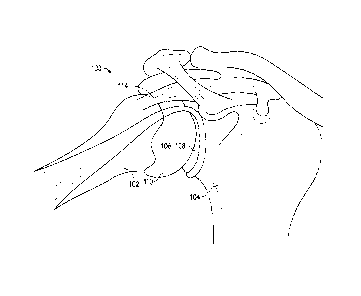
[0034] FIG. 1 is an anatomic view of a shoulder joint of a patient.
[0035] FIG. 2 is a schematic diagram of a prosthesis assembly installed
within the patient and
forming at least a portion of the shoulder joint.
[0036] FIGS. 3-3B show a humeral implant portion of the prosthesis assembly
having one or
more passages therein according to an example of the present application.
[0037] FIGS. 4-4B show a humeral implant portion of the prosthesis assembly
having one or
more passages therein according to another example of the present application.
[0038] FIG. 5 is a schematic diagram of a system for tissue repair and/or
joint replacement
including one or more sutures, a guide element, a part of the prosthesis
assembly and a suture
anchor, according to an example of the present application.
[0039] FIG. 6 is a schematic diagram of another a system for tissue repair
and/or joint
replacement, according to an example of the present application.
[0040] FIGS. 7A and 7B show another example of the guide element comprising
a bone cutting
needle, according to an example of the present application.
[0041] Corresponding reference characters indicate corresponding parts
throughout the several
views. The exemplifications set out herein illustrate examples of the
disclosure, and such
exemplifications are not to be construed as limiting the scope of the
disclosure any manner.
DETAILED DESCRIPTION
[0042] In describing the examples of the disclosure illustrated and to be
described with respect
to the drawings, specific terminology will be used for the sake of clarity.
However, the disclosure
is not intended to be limited to any specific terms or illustrations used
herein, and it is to be
understood that each specific term includes all technical equivalents.
[0043] The present disclosure is directed to systems and methods that can
be used in joint
replacement procedures to anchor soft tissue such as ligaments. The joint
replacement procedures
6
Date Recue/Date Received 2023-07-19
can be total or partial procedure such as an anatomic shoulder arthroplasty or
reverse shoulder
arthroplasty (RSA) procedure. Although the present methods, apparatuses and
systems are being
described in reference to a shoulder arthroplasty, the methods, apparatuses
and systems can be
used for other joints such as stems for the knee, hip, ankle or the like.
[0044] FIG. 1 illustrates a shoulder joint 100 with several ligaments
stripped away. As shown,
the shoulder joint 100 includes a humerus 102 and a scapula 104 that has a
glenoid 106 with a
socket 108 for interacting with a humeral head 110 of humerus 102. Humeral
head 110 can
articulate within socket 108 to allow for normal motion of the shoulder joint
100. A critical
ligament for maintaining humeral head 110 within socket 108 is the rotator
cuff 114. When rotator
cuff 114 becomes damaged (e.g., torn or degraded), normal shoulder joint
function can become
compromised. Since rotator cuff 114 is not functioning correctly, humeral head
110 can become
dislodged from glenoid 106 during normal motion. Alternatively, disease can
degenerate the bone
or soft tissue of the humeral head 110 and/or scapula 104. These can cause
pain and/or can
negatively impact shoulder joint function. Typically, in these cases a
surgical intervention may be
required. Surgical intervention can repair function of the rotator cuff 114.
If bone from the
shoulder joint 100 must be removed, the rotator cuff 114 must be detached from
the humerus 102
during the procedure and then reattached thereto. This surgical process can be
complex and time
consuming.
[0045] FIG. 2 illustrates a schematic diagram of a prosthesis assembly 116
installed at the
shoulder joint 100. The prosthesis assembly 116 can include a humeral implant
component 118
(also called a humeral component, humeral implant or humeral prosthesis
component, component
or similar herein) and a head component 120.
[0046] The humeral implant component 118 can be fitted into a recess 119
formed at a
proximal end portion 122 of the humerus 102. The embodiment of FIG. 2 (and
indeed the
embodiments of FIGS. 3-4B) show a stem-less or stem-free design for the
prosthesis assembly
116. Thus, the humeral implant component 118 does not couple with a stem,
which would be
typical in a total shoulder replacement procedure. The humeral implant
component 118 without
the stem can be used in a partial shoulder replacement procedure. It is
contemplated that the
systems and methods disclosed herein could be used with any applicable joint
replacement
procedure including a total shoulder replacement procedure. Thus, the concepts
of the present
application are not limited by the examples provided herein. Similarly, the
term "bone" as used
7
Date Recue/Date Received 2023-07-19
herein is not limited to the humerus but can include any applicable bone of
the body including the
scapula, for example.
[0047] As shown in FIG. 2, a proximal side 124 of the humeral implant
component 118 can
interface with the head component 120. The head component 120 can couple with
the humeral
implant component 118 using known mechanisms such as mating taper features or
the like. The
head component 120 can be semi-spherical or otherwise shaped to replicate the
head of the
humerus (which is removed during the joint replacement procedure).
[0048] FIGS. 3-3B show an example of a humeral implant component 218. The
humeral
implant component 218 (and indeed, the humeral implant component 318 of FIGS.
4-4B) can be
configured in the manner of the Sidus0 Stem-Free Shoulder prosthesis or
Comprehensive Nano
Stemless Shoulder commercially available and manufactured by Zimmer Biomet
Inc., of Warsaw
Indiana. The humeral implant component designs shown in FIGS. 2-4B are purely
exemplary and
are provided merely to facilitate practitioner understanding.
[0049] However, the humeral implant component 218 has been modified from
the commercial
products referenced above as further discussed herein. As shown in FIGS. 3,
the humeral implant
component 218 includes a proximal side 202 having a proximal surface 204, a
coupling component
208, a body 210 and distal anchoring features 212 including fins 214. FIG. 3A
shows a distal side
of the humeral implant component 218 including the body 210 and the distal
anchoring features
212 with fins 214. FIG. 3B shows the proximal side 202 with the proximal
surface 204.
[0050] The term "proximal" refers to the general orientation of the side
and/or surface when
the humeral implant component 218 is implanted in the bone. Thus, "proximal"
refers to a
direction or location generally in the direction of or toward the head of a
patient, and "distal" refers
to the opposite direction of proximal, i.e., away from the head of a patient.
As used herein, the
terms "anterior" and "posterior" should be given their generally understood
anatomical
interpretation. Thus, "posterior" refers to a location or direction generally
toward a rear of the
patient. Similarly, "anterior" refers to a location or direction generally
toward a front of the patient.
Thus, "posterior" refers to the opposite direction of "anterior." Similarly,
the terms "medial" and
"lateral" should be given their generally understood anatomical
interpretation. "Medial" refers to
the more inward facing (inner part) of the prosthesis (when in the implanted
orientation) and
"lateral" refers to the outer part or outward facing part. "Medial" refers to
the opposite direction
of "lateral."
8
Date Recue/Date Received 2023-07-19
[0051] As shown in FIGS. 3-3B, the humeral implant component 218 can also
include one or
more passages 216. The one or more passages 216 can include a first opening
220A, 220B (FIG.
3B only) and a second opening 222A, 222B (FIGS. 3 and 3A).
[0052] The first opening 220A, 220B of the one or more passages 216 can be
located at the
proximal side 202 in the proximal surface 204, for example. However, the first
opening could be
on other sides or in other components of the humeral implant component 218
according to other
examples. The second opening 222A, 222B can be located at any one or
combination of a lateral
side surface, a medial side surface, an anterior side surface, a posterior
side surface or a distal side
of the humeral implant component 218. As shown in FIGS. 3 and 3A, the second
opening 222A,
222B can be on both a side surface 224 and a distal side 226 of the humeral
implant component
218 such as at a lower side surface of the fins 214.
[0053] The one or more passages 216 can extend through the humeral implant
component 218
from the first opening 220A, 220B FIG. 3B only) to the second opening 222A,
222B (FIGS. 3 and
3A). The one or more passages 216 can be configured to direct a guide element
and can receive
suture(s) as further discussed herein.
[0054] The embodiment of FIGS. 3-3B shows a cementless design for the
humeral implant
component 218 with the coupling component 208 extending from the body 210. The
proximal side
202 can be formed by interconnected fins 214. The fins 214 can be part of the
anchoring features
212, which can extend from the body 210.
[0055] FIGS. 4-4B show a cemented design for the humeral implant component
318. The
humeral implant component 318 can be constructed in a manner similar to that
of the humeral
implant component 318 but a proximal side 302 with a proximal surface 304 can
be formed by
part of fins 314.
[0056] As shown in FIGS. 4-4B, the humeral implant component 318 can also
include one or
more passages 316. The one or more passages 316 can include a first opening
320A, 320B (FIG.
4B only) and a second opening 322A, 322B (FIGS. 4 and 4A).
[0057] The first opening 320A, 320B of the one or more passages 316 can be
located at the
proximal side 302 in the proximal surface 304 (a top part of the fins 314),
for example. However,
the first opening 320A, 320B could be on other sides or in other components of
the humeral implant
component 318 according to other examples. The second opening 322A, 322B can
be located at
any one or combination of a lateral side surface, a medial side surface, an
anterior side surface, a
9
Date Recue/Date Received 2023-07-19
posterior side surface or a distal side of the humeral implant component 318.
As shown in FIGS.
4 and 4A, the second opening 322A, 322B can be on both a side surface 324 and
a distal side 326
of the humeral implant component 318 such as at a lower side surface of the
fins 314.
[0058] The one or more passages 316 can extend through the humeral implant
component 318
from the first opening 320A, 320B FIG. 4B only) to the second opening 322A,
322B (FIGS. 4 and
4A). The one or more passages 316 can be configured to direct a guide element
(or instrument)
and can receive suture(s) as further discussed herein.
[0059] FIG. 5 shows a cross-section of a bone 400 of a patient along with a
portion of a
humeral implant component 418, which can be configured similar to any of the
humeral implant
components 118, 218 or 318, discussed previously). FIG. 5 show a proximal end
402 of the bone
400, which can comprise the humerus 102 according to one example. The bone 400
can include
cancellous bone 404 and cortical bone 406.
[0060] FIG. 5 shows a system 408 for tissue repair related to the joint
replacement. The system
408 can include the humeral implant component 418, one or more sutures 410, a
guide element
412, and a suture anchor 414. The humeral implant component 418 can include
one or more
passages 416 similar to those previously discussed and illustrated in FIGS. 3-
4B. The humeral
implant component 418 can additionally include a first opening 420, a second
opening 422 and a
first surface 424 (e.g., a proximal surface when implanted into the bone 400
as illustrate in FIG.
5) at a first side 425 (e.g., a proximal side when implanted into the bone
400).
[0061] The first opening 420 of the one or more passages 416 can be at the
first surface 424
as discussed with prior examples. The second opening 422 can be distal of the
first opening 420
on a second side 427 of the humeral implant component 418. The second opening
422 can be one
or more of lateral, medial, anterior or posterior side (at a periphery)
relative to the first opening
420. Location of the first opening 420 and the second opening 422 can be as
desired based upon
an anatomic location of the soft tissue to be repaired with the one or more
sutures 410.
[0062] The one or more passages 416 can guide the one or more sutures 410
and the guide
element 412 (or alternate instrument). The guide element 412 can be configured
to ease passage
of the one or more sutures 410 through the one or more passages 416.
Additionally, as shown in
the example of FIG. 5, the guide element 412 can be configured as a bone
cutting needle 426. The
bone cutting needle 426 can be configured to cut the bone 400 to form a
passage 428 therein. This
passage 428 can have an opening distal of the proximal end 402. The passage
428 can facilitate
Date Recue/Date Received 2023-07-19
the passage of the one or more sutures 410 from the one or more passages 416
outward from the
bone 400 at a location distal of the proximal end 402 of the bone 400.
[0063] The passage 428 can be formed after implantation of the humeral
implant component
418 and with the guiding aid of the one or more passages 416. Although FIG. 5
shows the guide
element 412 as the bone cutting needle 426, according to other embodiments
another tool or tools
capable of cutting bone and/or passing suture could be utilized. For example,
the guide element
412 could be a drill that can be guided through the one or more passages 416
to the bone 400 to
form the passage 428. A second element such as a suture passer could then be
utilized to ease or
facilitate passage of the one or more sutures 410 through the one or more
passages 416 and the
passage 428.
[0064] The configuration of the one or more passages 416 and the passage
428 provided is
purely exemplary and other angles, sizes, shapes, number, etc. are
contemplated in other examples.
[0065] The one or more sutures 410 can be coupled to the bone cutting
needle 426 at a first
end 430 and can be coupled to the suture anchor 414 at a second end 432. The
bone cutting needle
426 can be crimped or otherwise coupled to the first end 430 of the one or
more sutures 410. The
second end 432 may be a loop, such that a single suture can be utilized
according to some
examples. Multiple sutures of different sizes, types, colors and shapes are
contemplated. Any
type of suture as known in the art, (e.g., broadband, ribbon, round, mesh,
braided, monofilament,
metal, polymer, etc.) can be utilized. Thus, the system 408 can utilize multi-
loaded or single-
loaded suture.
[0066] The suture anchor 414 can be of any suitable construct as known in
the art. Thus, the
suture anchor 414 can be hard sided so as to be substantially non-deformable
upon deployment
into/against the tissue of the patient (e.g., constructed as a button or
another feature as known in
the art). As shown in FIG. 5 the suture anchor 414 can be "soft" (e.g., they
can be made from a
relatively soft material such as fabric or suture), and thus they can bend,
flex and/or deform under
the force of a suture. In some examples, the suture anchor 414 can be
nominally shaped as
cylinders, or tubes having a circular or elongated cross-section with a
passage therethrough.
However, the suture anchor 414 can be configured to deform during deployment
such as by
bending (as shown in FIG. 5) knotting (as shown in FIG. 6), or otherwise
changing shape. Put
another way, the suture anchor 414 can comprise a deformable member having a
passage
therethrough. This deformable member can be configured to be collapsible upon
engagement with
11
Date Recue/Date Received 2023-07-19
the prosthesis to form an anchoring mass having a locking profile. As shown in
FIG. 5, the locking
profile of the suture anchor 414 can be configured to engage and anchor
against the first surface
424 and/or parts of the one or more of the one or more passages 416. The
suture anchor 414 can
initially be freely placed on the first surface 424 or another location
without the need for an inserter
or other instrument prior to deployment of the suture anchor 414 to stabilize
and hold the one or
more suture 410 as shown in FIG. 5. This eliminates the need for dedicated
deployment
instruments for the suture anchor 414. According to the example of FIG. 5, the
one or more sutures
410 and the suture anchor 414 can be a self-locking and/or adjustable loop
suture assembly such
as described in U.S. Patent Pub. Nos. 2014/0330311 and 2014/0046368, the
disclosures of each of
which is incorporated by reference herein in its entirety. Further examples of
a self-locking and/or
adjustable loop suture are exemplified in Applicant's ZipLoop0 and/or
ToogleLocTm Technology,
which is commercially available and manufactured by Zimmer Biomet Inc., of
Warsaw Indiana.
[0067] As discussed previously, it is also contemplated herein that one or
more anchors
utilized in the system may not be "soft" in the manner of the ZipLoop0.
Rather, these anchors
can be made from substantially non-deformable material such as a hard plastic,
metal alloy, etc.
Thus, according to some examples the anchor(s) can have a cross-section or
other geometry that
is substantially invariant. These non-deformable anchor(s) can have a hollow
interior formed by
a tubular or other shape of the anchor(s).
[0068] Although a single suture anchor is illustrated in FIG. 5, in some
embodiments it is
contemplated that further anchors (e.g., two, three, four or more) could be
used with the humeral
implant component 418. The suture anchors could be differently sized/shaped
relative to one
another and/or can be formed of different material relative to one another
according to some
examples.
[0069] The system 408 include the suture anchor 414, which can be
configured to couple with
the one or more sutures. The humeral implant component 418 (example of a
prosthesis) can be
configured to be inserted in the bone 400. The suture anchor 414 can be
configured to couple with
the humeral implant component 418 at one or more of the first surface 424, the
one or more
passages 416 or another location. The one or more sutures 410 can be
configured to pass through
the humeral implant component 418 via the one or more passages 416. The one or
more sutures
410 can be anchored to the humeral implant component 418, and hence the bone
400, via the suture
anchor 414 when the suture anchor 414 is deployed against the humeral implant
component 418.
12
Date Recue/Date Received 2023-07-19
[0070] To restore normal shoulder function, the one or more sutures 410 can
engage with the
rotator cuff (see FIG. 1) to lock the rotator cuff into position and anchor it
relative to the bone 400.
The one or more sutures 410 can thus provide tension and/or constraint needed
during healing of
the rotator cuff. The length of the one or more sutures 410 can be 12 inches
to 48 inches, inclusive.
However, other lengths as appropriate are contemplated.
[0071] The one or more sutures 410 can be spaced around part or the
entirety of or only a
portion of humeral implant component 418. A surgeon can choose to place the
one or more sutures
410 along a certain location(s) and certain of the one or more passages 416
may not be utilized. A
surgeon may choose to tension certain of the one or more sutures 410 (and/or
one or more suture
anchors 414) differently to apply an appropriate amount of tension to the soft
tissue.
[0072] In operation, as discussed above, the bone 400 would be prepared to
receive the
humeral implant component 418 by forming a recess therein. The humeral implant
component
418 would be implanted in the bone 400. Once the humeral implant component 418
is implanted,
the bone cutting needle 426 would be guided by the one or more passages 416 to
form the passage
428. The one or more sutures 410 would be passed through the one or more
passages 416 and the
passage 428 with the bone cutting needle 426. The bone cutting needle 426 can
then be removed
from coupling with the one or more sutures 410. The one or more sutures 410
can then be coupled
to the soft tissue and tensioned as desired and this process can deploy the
suture anchor 414 to
anchor against the humeral implant component 418. In this manner, the soft
tissue via the one or
more sutures 410 can be anchored to the bone 400 (via the humeral implant
component 418
engaged by the suture anchor 414).
[0073] FIG. 6 shows the system 408 including the humeral implant component
418, one or
more sutures 410, the guide element 412, and the suture anchor 414. FIG. 6
differs from FIG. 5 in
that the suture anchor 414 is captured by a dedicated surface, surface 429,
which is not part of the
first surface 424. Thus, the surface 429 can be recessed from the first
surface 424 (formed by a
counterbore). Although a counterbore with recessed surface 429 is shown,
alternative surface(s)
such as side, dedicated or projecting surfaces could be utilized for anchoring
the suture anchor
414. Additionally, the suture anchor 414 of FIG. 6 is deformed into a knot
structure 500 as the
locking profile. According to other examples, the knot structure 500 can be at
least partially
engaging the surface 429 adjacent the first side 425 in addition to engaging
sides of the one or
more passages 416. Although not illustrated in FIGS. 5 or 6, the one or more
passages 416 can be
13
Date Recue/Date Received 2023-07-19
configured as desired to facilitate engagement by the suture anchor 414 (e.g.,
the one or more
passages 416 can be provided with a restricted section, counterbore or the
like). The guide element
412 can be an inserter 502 rather than a bone cutting needle. A second guide
element such as a
drill for forming passages in the bone is not illustrated in FIG. 6. It is
contemplated that the terms
"first surface" and "first side" need not be limited to a proximal surface and
proximal side unless
so specified. Rather, these terms can be another surface (e.g., recessed,
proud, dedicated, side,
distal, etc.) and can be on any side of the implant.
[0074] FIGS. 7A and 7B show examples of a curved bone cutting needle 626
that can be
utilized according to some examples. The bone cutting needle 626 is curved
relative to a
longitudinal axis LA. The bone cutting needle 626 can be configured for
crimping connection to
the one or more sutures (not shown).
[0075] It will be readily understood to those skilled in the art that
various other changes in the
details, material, and arrangements of the parts and method stages which have
been described and
illustrated in order to explain the nature of the inventive subject matter can
be made without
departing from the principles and scope of the inventive subject matter as
expressed in the
subjoined claims. For example, the order of method steps or stages can be
altered from that
described above, as would be appreciated by a person of skill in the art.
[0076] It will also be appreciated that the various dependent claims,
examples, and the features
set forth therein can be combined in different ways than presented above
and/or in the initial
claims. For instance, any feature(s) from the above examples can be shared
with others of the
described examples, and/or a feature(s) from a particular dependent claim may
be shared with
another dependent or independent claim, in combinations that would be
understood by a person of
skill in the art.
[0077] The above detailed description includes references to the
accompanying drawings,
which form a part of the detailed description. The drawings show, by way of
illustration, specific
embodiments in which the invention can be practiced. These embodiments are
also referred to
herein as "examples." Such examples can include elements in addition to those
shown or
described. However, the present inventors also contemplate examples in which
only those
elements shown or described are provided. Moreover, the present inventors also
contemplate
examples using any combination or permutation of those elements shown or
described (or one or
14
Date Recue/Date Received 2023-07-19
more aspects thereof), either with respect to a particular example (or one or
more aspects thereof),
or with respect to other examples (or one or more aspects thereof) shown or
described herein.
[0078] In the event of inconsistent usages between this document and any
documents so
incorporated by reference, the usage in this document controls. In this
document, the terms
"including" and "in which" are used as the plain-English equivalents of the
respective terms
"comprising" and "wherein." Also, in the following claims, the terms
"including" and
"comprising" are open-ended, that is, a system, device, article, composition,
formulation, or
process that includes elements in addition to those listed after such a term
in a claim are still
deemed to fall within the scope of that claim.
[0079] In this document, the terms "a" or "an" are used, as is common in
patent documents, to
include one or more than one, independent of any other instances or usages of
"at least one" or
"one or more." In this document, the term "or" is used to refer to a
nonexclusive or, such that "A
or B" includes "A but not B," "B but not A," and "A and B," unless otherwise
indicated. In this
document, the terms "including" and "in which" are used as the plain-English
equivalents of the
respective terms "comprising" and "wherein." Also, in the following claims,
the terms "including"
and "comprising" are open-ended, that is, a system, device, article,
composition, formulation, or
process that includes elements in addition to those listed after such a term
in a claim are still
deemed to fall within the scope of that claim. Moreover, in the following
claims, the terms "first,"
"second," and "third," etc. are used merely as labels, and are not intended to
impose numerical
requirements on their objects.
[0080] The above description is intended to be illustrative, and not
restrictive. For example,
the above-described examples (or one or more aspects thereof) may be used in
combination with
each other. Other embodiments can be used, such as by one of ordinary skill in
the art upon
reviewing the above description. The Abstract is provided to comply with 37
C.F.R. 1.72(b), to
allow the reader to quickly ascertain the nature of the technical disclosure.
It is submitted with the
understanding that it will not be used to interpret or limit the scope or
meaning of the claims. Also,
in the above Detailed Description, various features may be grouped together to
streamline the
disclosure. This should not be interpreted as intending that an unclaimed
disclosed feature is
essential to any claim. Rather, inventive subject matter may lie in less than
all features of a
particular disclosed embodiment. Thus, the following claims are hereby
incorporated into the
Detailed Description as examples or embodiments, with each claim standing on
its own as a
Date Recue/Date Received 2023-07-19
separate embodiment, and it is contemplated that such embodiments can be
combined with each
other in various combinations or permutations. The scope of the invention
should be determined
with reference to the appended claims, along with the full scope of
equivalents to which such
claims are entitled.
16
Date Recue/Date Received 2023-07-19