Note: Descriptions are shown in the official language in which they were submitted.
CA 03207739 2023-07-10
Device for the manufacture of skewers of food products
comprising a mobile skewer picker synchronized with the
movement of the trays for receiving the food products
1. Field of the invention
The invention relates to a device for manufacturing
skewers including two mobile trays positioned on top of
each other by forming aligned cavities intended to
receive foodstuffs. The invention relates more
particularly to the fact that it includes a mechanism
for transferring and positioning spikes in the axis of
the cavities when the latter skewer the foodstuffs.
2. Prior art
The invention is in the field of food. Professionals
have portioning apparatuses that allow to produce
individual portions from a product produced in large
quantities by disposing them on spikes to facilitate
cooking. More specifically, the present invention
relates to a device for manufacturing skewers wherein
various and varied foodstuffs are aligned and skewered
on a straight spike.
Producing skewers first involves cutting compact
food products such as: pieces of meat, whole or cut
vegetables, fruit, sausages, diced cheese, etc. These
different foods can be skewered manually on a spike, one
after the other. Spikes can be simple, thin pieces of
wood elongated and sharpened at one end, bamboo for
example, these spikes being generally disposable. In
some cases, the non-pointed end has a flattened end for
better grip, or a sculpted head with a pattern.
Date Regue/Date Received 2023-07-10
CA 03207739 2023-07-10
2
Other spikes exist in metal. They have the same
elongated shape and have a pointed end and another
forming a loop for gripping.
The skewering operation done by hand is delicate
and takes considerable time. Indeed, it is difficult for
an operator to centre the spike in the middle of pieces
of food products that are not immobilised, the risk being
to sink the spike into the hand. On the other hand, food
products have very different consistencies, viscosities
and shapes and therefore the force to pass therethrough
must be adapted accordingly. Finally, there is a large
multitude of spikes of different shapes and diameters
which increase the difficulty of the operation.
A device for manually manufacturing skewers aiming
at facilitating the skewering of foodstuffs on spikes in
order to constitute skewers is known in particular from
patent application FR 3 076 185, belonging to the
applicant of the present application. Such a device
comprises a fixed base and a mobile assembly mounted to
slide on the fixed base. The mobile assembly comprises
lower and upper trays carrying at least one mould and at
least one counter mould respectively. When the trays are
positioned on top of each other, the mould and the
counter-mould form longitudinal cavities capable of
containing the food products previously disposed on the
mould. The fixed base further carries a retractable guide
system formed of three plates each comprising notches
made so as to hold the spikes coaxially with the axes of
the cavities. Once the food products are held in the
cavities and the spikes placed in the guide system, the
skewering of the food products on the spikes is carried
Date Regue/Date Received 2023-07-10
CA 03207739 2023-07-10
3
out by sliding the mobile assembly towards the spike
guiding system. The spikes are thus correctly centred in
the middle of the food products. Such a device is
advantageous but does not entirely satisfy the fact that
it requires the manual positioning of the spikes which
can be time-consuming. Indeed, after or before
depositing and positioning the foodstuffs in the
dedicated cavities, the operator must take then position
the skewering spikes one by one in the notches of the
guide system. The operation of positioning the spikes
intervenes in the cycle of the operations of pulling and
pushing the trays and of the operations of opening the
trays and removing the skewers produced. The repetition
of these actions therefore generates a certain muscular
fatigue for the operator who becomes less rapid and/or
precise during the execution of the operation of
positioning the spikes.
There is therefore a real need for a solution
allowing to simplify the operation and improve the rate
of skewer production devices to properly align
foodstuffs so that the spikes pass therethrough right in
the centre.
3. Objectives of the invention
The invention aims at proposing a new apparatus for
manufacturing skewers, including a mould and a counter-
mould allowing to immobilise the foodstuffs during
skewering and to centre them in the middle of the spikes
of the skewers, allowing the automatic positioning of a
spike in the skewering position, thus minimising
operator interventions.
Date Regue/Date Received 2023-07-10
CA 03207739 2023-07-10
4
4. Disclosure of the invention
In order to solve at least the problems mentioned
above, the present invention proposes a device for
manufacturing at least one skewer comprising a frame and
a carriage mounted to slide on the frame between a front
position and a rear position, and vice versa, the mobile
carriage comprising a lower tray cooperating with an
upper tray, forming a cover, the upper tray being mounted
to move between an open position and a closed (or folded)
position, the lower and upper trays having recesses for
receiving foodstuffs forming at least one row of aligned
cavities when the upper tray is folded onto the lower
tray and at least one orifice for passing a spike opening
into the axis of the at least one row of aligned cavities,
the skewering of the spike in the foodstuffs housed in
the at least one row of aligned cavities being carried
out by moving the mobile carriage from the rear position
(also called the retracted position) to the front
position (also called the forward position).
According to the invention, the skewer production
device comprises at least one spike reservoir and one
mobile spike extractor configured to selectively take at
least one spike from said at least one reservoir, and to
extract said at least one spike taken from the reservoir
so as to position it facing the at least one orifice
when the mobile carriage is in the rear position, and
further comprises first synchronisation means configured
to synchronise the movement of the mobile spike extractor
with the movement of the mobile carriage comprising the
trays.
Date Regue/Date Received 2023-07-10
CA 03207739 2023-07-10
The spike extractor is therefore, within the
meaning of the proposed technique, a mobile element which
ensures the removal or disengagement of at least one
spike from the reservoir. For this purpose, the mobile
5 spike extractor therefore engages at least partially,
and temporarily, inside the reservoir to take a spike,
then to extract it from the reservoir.
A device for manufacturing skewers having such
means for synchronising the movement of the mobile spike
extractor with the movement of the mobile carriage,
allows the automatic placement of the spikes in the
skewering position. With a device in accordance with the
proposed technique, except for disposing the foodstuffs
in the cavities and recovering the produced skewers, the
operator advantageously keeps his or her hands on the
handles of the mobile carriage throughout the production
process. This is advantageous compared to the prior art
wherein the manual deposition of the spikes is time-
consuming and requires special attention from the
operator.
The movement of the mobile spike extractor being
carried out during the movement of the mobile carriage
(because it is connected thereto), the placement of the
spikes is also immediate in the sense that it does not
cause any interruption, or a negligible interruption, in
the handling of the mobile carriage. Therefore, this
results in particular in an increase in production rates
and in an improvement in the comfort and working
conditions of the operator.
Moreover, the automatic placement of the spikes in
the skewering position is carried out by the device for
Date Regue/Date Received 2023-07-10
CA 03207739 2023-07-10
6
manufacturing skewers itself. This allows the device to
be autonomous, that is to say not to depend on an
external installation dedicated to positioning the
spikes. The device is thus easily transportable and,
once it is installed, quickly usable.
According to a particular embodiment, the mobile
spike extractor is mounted to slide on the frame between
a low position and a high position, and vice versa, the
extraction and the positioning of the spikes facing the
at least one orifice being carried out by moving the
mobile spike extractor from the low position to the high
position. Furthermore, the synchronisation means are
configured to synchronise:
- the raising of the mobile spike extractor from
the low position to the high position with the movement
of the mobile carriage from the front position to the
rear position, corresponding to a backward movement of
the mobile carriage, and
- the lowering of the mobile spike extractor from
the high position to the low position with the movement
of the mobile carriage from the rear position to the
front position, corresponding to a forward movement of
the mobile carriage.
The back and forth horizontal movement of the trays
allows to raise and lower the blade(s) which select the
spike(s) in the spike reservoir. In other words, the
steps of pushing the trays away from the operator and
pulling the trays towards the operator are synchronised
with the raising and lowering of the spike selection
system.
Date Regue/Date Received 2023-07-10
CA 03207739 2023-07-10
7
Such an arrangement, which is particularly
advantageous when the spike reservoir is located below
the mobile carriage, allows to minimise the space
requirement of the device for manufacturing skewers.
Thus, the device can be easily transported. It can also
be easily stored and/or installed in relatively confined
storage and/or work spaces.
According to another particular embodiment, the
synchronisation means comprise at least one
synchronisation lever pivotally mounted on the frame and
having:
- a first end connected to the mobile spike
extractor, and
- a second end, supporting a second roller disposed
inside a synchronisation track formed on the mobile
carriage, the synchronisation track having a first end,
associated with the low position of the mobile spike
extractor, and a second end, associated with the high
position of the mobile spike extractor.
Such mechanical synchronisation means allow to
ensure precise and efficient synchronisation of the
movement of the mobile spike extractor with the movement
of the mobile carriage. The absence of electronic means
further allows a device comprising such synchronisation
means to be used in a cold and/or humid working
environment, in particular while minimising the risk of
breakdowns and/or malfunctions, for example. Such
mechanical synchronisation means are moreover simple in
design and therefore simple to maintain.
According to another particular embodiment, the
synchronisation lever has at its first end an oblong
Date Regue/Date Received 2023-07-10
CA 03207739 2023-07-10
8
aperture cooperating with a first roller carried by the
mobile spike extractor so that the pivoting of the
synchronisation lever causes the movement of the first
roller and the movement of the mobile spike extractor
between the high and low positions, and vice versa.
Such a structure of the synchronisation lever
constitutes a simple and effective solution for
obtaining fluid, therefore non jerky, and precise
guiding of the mobile spike extractor between the high
and low positions, and vice versa. In particular, this
reduces the risk of undesired ejection of the spikes
from the mobile spike extractor when the latter is raised.
According to another particular embodiment, the
mobile spike extractor comprises a crosspiece carrying
the first roller, the frame and the crosspiece carrying
sliding means allowing the vertical movement of the
mobile spike extractor between the high and low positions,
and vice versa.
According to another particular embodiment, the
synchronisation track comprises first and second paths
extending between the first and second ends of the
synchronisation track, the first path being configured
to be taken by the second roller when the mobile carriage
moves back, the second path being configured to be taken
by the second roller when the mobile carriage moves
forward.
Such a configuration of the synchronisation track
allows to prevent the spike carried by the mobile spike
extractor from hitting the mobile carriage while
allowing the mobile spike extractor to hold the spike in
a stable position until it begins to enter the cavities
Date Regue/Date Received 2023-07-10
CA 03207739 2023-07-10
9
comprising the foodstuffs. This eliminates the need to
implement a dedicated system for guiding and positioning
the spike in accordance with previous solutions. This
allows in particular to simplify the construction of the
device.
According to another particular embodiment, the
production device comprises at least one one-way shutter
allowing the movement of the second roller inside the
first path when the mobile carriage moves back and
preventing the second roller from moving inside the first
path when the mobile carriage moves forward to guide the
second roller in the second path.
According to another particular embodiment, the
mobile spike extractor further comprises at least one
spike extraction blade having on its upper face a groove
for receiving and holding a spike from the reservoir.
The use of a blade, which is intrinsically a thin
element, allows to prevent other spikes present in the
reservoir from remaining balanced on a portion of the
extraction blade or on the spike engaged on the blade in
question. Such a blade further allows to limit the number
of spikes moved in the reservoir when raising and
lowering the blades therethrough. Therefore, this
results in a reduction in the risk of ejection of the
spikes outside the reservoir.
Moreover, the implementation of a groove on the
upper part of the blade allows to minimise the risk of
the extracted spike falling back into the reservoir when
handling the device by the operator.
According to another particular embodiment, the
spike extraction blade is disposed inside a slot formed
Date Regue/Date Received 2023-07-10
CA 03207739 2023-07-10
in the bottom of the spike reservoir when the mobile
spike extractor is in the low position, the extraction
blade having a lower portion disposed inside the slot
when the mobile spike extractor is in the high position.
5 Such a lower portion allows to avoid, in the absence
of the extraction blade in the slot, that the spikes
present in the reservoir escape therefrom through the
slots under the effect of gravity, or that unused spikes
block the lowering of the extraction blade. Such a lower
10 portion thus allows to minimise the risk of accident for
the operator, by preventing him from falling after having
walked on spikes that have fallen to the ground, for
example, and to minimise the risk of malfunction, or
even deterioration, of the skewer production device.
According to another particular embodiment, the
frame comprises at least one stop for positioning a spike
against which the spike, disposed in the groove for
receiving and holding the extraction blade in the high
position of the mobile spike extractor, bears at the
start of skewering the spike in the foodstuffs housed in
the row of aligned cavities.
Such a positioning stop allows, after the
initiation of the skewering operation, to immobilise the
base of the spike in order to prevent it from becoming
misaligned, or even that it breaks or is ejected. This
allows in particular to prevent the operator from having
to manually reposition or replace the spike. This further
allows to minimise the risk of damage to the skewer
production device, if for example a shard of a spike
were to jam in the synchronisation means.
Date Regue/Date Received 2023-07-10
CA 03207739 2023-07-10
11
According to another particular embodiment, the
production device comprises at least one deformable tab
capable of holding the spike in the groove for receiving
and holding the extraction blade in the high position of
the mobile spike extractor.
Such a deformable tab allows to hold the spike in
position in order to prevent it from being accidentally
ejected at the end of the backward movement phase of the
mobile carriage, and therefore when the mobile spike
extractor reaches the high position. It has indeed been
observed by the inventors that the device for
manufacturing skewers was subject to vibrations mainly
when the mobile carriage and/or the mobile spike
extractor contact the end-of-stroke stops. Such
vibrations can also appear when the mobile carriage
and/or the mobile spike extractor are subject to
significant decelerations or accelerations. These
decelerations or accelerations essentially appear when
the mobile carriage and/or the extractor arrive in the
vicinity of the end-of-stroke stops, in order to avoid
a shock against the latter. The implementation of the
tabs allows to optimise the operation of the device by
avoiding interrupting the production process to ensure
manual repositioning of the spike and allows the operator
to use the device dynamically without having to adjust
or control how to push or pull the mobile carriage.
According to another particular embodiment, the
deformable tab is positioned on said frame below the
positioning stop, and the deformable tab is in the shape
of a loop having an opening for the passage of a spike
carried by an extraction blade of the mobile spike
Date Regue/Date Received 2023-07-10
CA 03207739 2023-07-10
12
extractor, the deformable tab being bent towards the
reservoir when the mobile spike extractor is in the low
position and bent in the opposite direction when the
mobile spike extractor is in the high position, a spike
passing through the passage opening in the high position
of the mobile spike extractor.
Such an arrangement and such a configuration of the
deformable tab allow in particular the passage of the
spike through the opening dedicated to this purpose. The
advantage of this configuration is twofold, namely to
allow the spike to bear against the positioning stop at
the start of skewering, and therefore not to disturb the
operation of the device, and to allow the upper and side
edges of the spike to be held in order to optimise
holding the spike in the skewering position.
According to another particular embodiment, the
recesses of the lower and upper trays respectively
support at least one mould and at least one counter mould
made of a flexible material.
This allows not to damage the foodstuffs disposed
in the cavities. Preferably, the mould(s) and counter
mould(s) are made of silicone.
5. List of the figures
Other features and advantages of the invention will
appear more clearly upon reading the following
description of particular embodiments, given by way of
simple illustrative and non-limiting examples, and the
appended drawings, among which:
- [Fig.1A], [Fig.1B] and [Fig.1C]: Figures 1A to 1C
show, according to perspective views and in different
Date Regue/Date Received 2023-07-10
CA 03207739 2023-07-10
13
positions, an example of a skewer production device
according to a first embodiment of the proposed technique;
- [Fig.2]: Figure 2 shows, in a partial perspective
view, an example of mobile spike extractor mounted on
the frame of the skewer production device according to
Figures 1A to 1C;
- [Fig.3A], [Fig.3B], [Fig.3C] and [Fig.3D]:
Figures 3A to 3D show, according to partial perspective
views, an example of means for synchronising a device
for manufacturing skewers according to Figures 1A to 1C;
- [Fig.4A] and [Fig.4B]: Figures 4A and 4B show,
according to different focused perspective views, an
example of a one-way shutter mounted in a synchronisation
track forming part of the synchronisation means of
Figures 3A to 3D;
- [Fig.5A], [Fig.5B], [Fig.5C] and [Fig.5D]:
Figures 5A to 5D show, in different views, the operation
of the one-way shutter of Figures 4A and 4B;
- [Fig.6]: Figure 6 shows, in a perspective view,
an example of a spike reservoir of the skewer production
device according to Figures 1A to 1C;
- [Fig.7A] and [Fig.7B]: Figures 7A and 7B show, in
cross-sectional views, the interactions between the
spike extraction blades carried by the mobile spike
extractor according to Figure 2 and the spike reservoir
according to Figure 6;
- [Fig.8A], [Fig.8B] and [Fig.8C]: Figures 8A to 8C
show, in different views and in different positions,
deformable tabs of the skewer production device
according to Figures 1A to 1C;
Date Regue/Date Received 2023-07-10
CA 03207739 2023-07-10
14
- [Fig.9]: Figure 9 is a flowchart of the main
operating steps of a skewer production device according
to Figures 1A to 1C;
- [Fig.10A], [Fig.10B],
[Fig.10C], [Fig.11A],
[Fig.11B], [Fig.11C], [Fig.12A], [Fig.12B], [Fig.12C],
[Fig.13A], [Fig.13B], [Fig.13C], [Fig.14A], [Fig.14B],
[Fig.14C], [Fig.15A], [Fig. 15B] and [Fig.15C]: [Fig.9]:
Figures 10A to 15C show, according to different views,
the skewer production device according to Figures 1A to
1C in different operating positions.
6. Description of an embodiment of the invention
For the sake of clarity, the same elements were
designated by the same references in the various figures.
Moreover, in the present description, the terms of
orientation and positioning "lower", "upper", "front",
"rear", etc. are used by arbitrarily referring to a
normal position of use of a skewer production device,
wherein two trays positioned on top of each other are
mobile in a plane approximately parallel to the ground
(horizontal) and slide between a proximal (front) and
distal (rear) position relative to positioning stops of
the spikes in the trays. When using such a device, the
operator is located on the side of the positioning stops.
6.1 General principle
The invention relates to a device for manufacturing
one or more skewers. Such a device comprises a frame and
a mobile carriage mounted to slide on the frame between
a front position and a rear position, and vice versa.
The mobile carriage comprises a lower tray cooperating
Date Regue/Date Received 2023-07-10
CA 03207739 2023-07-10
with an upper tray, forming a cover. The upper tray is
mounted to move between an open position and a closed or
folded position. The lower and upper trays have recesses
for receiving foodstuffs forming a row of aligned
5 cavities when the upper tray is folded onto the lower
tray and an orifice for passing a spike opening into the
axis of the row of aligned cavities. The skewering of
the spikes in the food products housed in the aligned
cavities is carried out by moving the mobile carriage
10 from the rear position to the front position. The device
further comprises a spike reservoir, a mobile spike
extractor configured to selectively extract one or more
spikes from the reservoir. For this purpose, the
extractor is configured to be introduced at least
15 partially and temporarily into the reservoir in order to
take and extract one or more spikes therefrom, and
position the spike(s) facing the corresponding passage
orifice when the mobile carriage is in the rear position.
The device also comprises synchronisation means
configured to synchronise the movement of the mobile
spike extractor with the movement of the mobile carriage.
In this way, the front-to-back movement of the
mobile carriage allows to extract spikes from the
reservoir by means of the mobile extractor and to place
them in position for skewering while the back-to-front
movement of this same mobile carriage allows the
skewering of the foodstuffs disposed between the trays
on the spikes.
This front-to-back movement of the mobile carriage,
and vice versa, is ensured by an operator using handles
disposed on the mobile carriage. Without removing his
Date Regue/Date Received 2023-07-10
CA 03207739 2023-07-10
16
hands from the handles, the operator can on the one hand
automatically extract spikes from the reservoir by
pushing back the mobile carriage (this step being ensured
by the extractor which passes through the reservoir and
takes, as it passes, one or more spikes in order to
extract them from the reservoir), then skewer the food
products on the spikes thus extracted by bringing the
mobile carriage towards him.
In other words, certain steps in the operation of
the skewer production device are carried out
simultaneously, and in particular the movement of the
mobile carriage which is synchronised with the movement
of the spikes stored in the reservoir. The operator is
no longer forced to manually position spikes facing the
trays before skewering.
Therefore, this translates into a simplification of
the use of the skewer production device and an
improvement in productivity.
6.2 Description of an embodiment
6.2.1 Device for manufacturing skewers
Figures 1A to 1C show in perspective, according to
different views, an example of a device for manufacturing
skewers wherein the movement of a mobile spike extractor,
configured to take and extract spikes from a reservoir
of the device and place the extracted spikes in position
for skewering foodstuffs, is synchronised with the
movement of a mobile carriage carrying pivoting trays,
in accordance with the proposed technique.
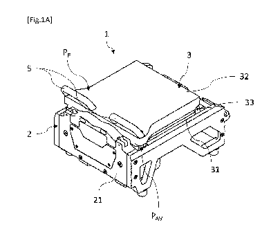
The device 1 for manufacturing skewers comprises a
frame 2 equipped with feet intended to place the device
Date Regue/Date Received 2023-07-10
CA 03207739 2023-07-10
17
1 on a surface, which is preferably horizontal. The frame
2 further comprises a rectangular empty space (not
referenced) intended to receive other elements of the
device as will be seen in more detail later.
The device 1 also comprises a mobile carriage 3
comprising a first tray 31, called the lower tray, and
a second tray 32, called the upper tray. The lower tray
31 is disposed in the rectangular empty space of the
frame 2. The upper tray 32, forming a cover, is pivotally
mounted on the mobile carriage 3, by means of a hinge
33, between a closed or folded position PE, shown in
Figure 1A, and an open position P., shown in Figures 1B
in particular.
The lower and upper trays 31, 32 respectively have
recesses 310, 320 for receiving foodstuffs forming, when
the upper tray 32 is folded onto the lower tray 31,
parallel rows of aligned cavities. Each recess, and
therefore each cavity formed by the superposition of two
recesses belonging respectively to the lower and upper
trays, extends longitudinally along an axis X. The axis
X further defines the longitudinal axis of the device 1.
Furthermore, the lower and upper trays 31, 32 have
respectively on one of their edges complementary notches
forming, when the upper tray 32 is folded onto the lower
tray 31, orifices 34 for the passage of a spike. Each
orifice 34 is oriented along the longitudinal axis X of
a cavity and opens inside the latter, as illustrated in
relation to Figure 1C in particular.
Moreover, the mobile carriage 3 is mounted to slide
on the frame 2 along the longitudinal axis X between a
front position PNyand a rear position PAR, and vice versa.
Date Regue/Date Received 2023-07-10
CA 03207739 2023-07-10
18
In the front position PAv, as illustrated in
relation to Figure 1A in particular, the mobile carriage
3 is substantially pressed against the positioning stops
4 of the spikes, on the side of the user. These
positioning stops 4 of the spikes, which are more visible
in Figure 8A in particular, are carried by a front
portion 21 of the frame 2 on the side of which the user
is positioned to handle the device. The positioning stops
4 are configured to immobilise the base of the spikes,
that is to say the end of the spike opposite the tip, so
as to prevent the unwanted movement of the spikes along
the longitudinal axis X during the operation of skewering
the foodstuffs on the spikes. When the mobile carriage
3 is moved by the operator using handles from the rear
position PAR to the front position PAv, that is to say
when the operator pulls the mobile carriage towards him,
the foodstuffs is thus skewered on the spikes.
In the rear position PAR, as illustrated in relation
to Figure 1C in particular, the mobile carriage 3 is
moved away from the positioning stops 4 by a distance
greater than the length of the spikes P so as to allow
the positioning of a spike extracted from the reservoir
facing each of the orifices 34 of the mobile carriage 3.
The skewering of the food products housed in the cavities
on the spikes is therefore carried out by moving the
mobile carriage 3 from the rear position PAR to the front
position Pmi.
The device 1 for manufacturing skewers further
comprises two handles 5 placed at the front of the upper
tray 32, that is to say opposite the hinge 33. The
handles 5 allow to animate the pivoting of the upper
Date Regue/Date Received 2023-07-10
CA 03207739 2023-07-10
19
tray 32 as well as the sliding of the mobile carriage 3
relative to the frame 2. Alternatively, the device may
comprise a single handle when it allows the
aforementioned operations to be carried out.
Moreover, the device 1 comprises a reservoir 10 of
unused spikes which extends along the longitudinal axis
X of the device 1. The reservoir 10 is disposed inside
the rectangular empty space of the frame 2, below the
lower tray 31 of the mobile carriage 3, and is
irremovably fixed to the frame 2.
According to the invention, the device 1 further
comprises a mobile spike extractor, configured to
selectively take and extract spikes from the reservoir
10 initially, then to position a spike extracted from
the reservoir facing each of the orifices 34 when the
mobile carriage 3 is in the rear position PAR. The device
1 moreover comprises synchronisation means configured to
synchronise the movement of the mobile spike extractor
with the movement of the mobile carriage 3. The mobile
spike extractor and the synchronisation means, not
visible in Figures 1A, 1B and 1C, will be described in
detail later.
In the exemplary embodiment illustrated in relation
to the figures, the device 1 comprises two aligned
cavities for receiving food products, which are formed
by the recesses 310, 320, and is thus capable of
manufacturing two skewers at the same time. This number
is only given by way of example, the device according to
the invention can also be adapted to the production of
a single or three or nine, or any number of skewers,
depending in particular on the number of aligned cavities
Date Regue/Date Received 2023-07-10
CA 03207739 2023-07-10
for receiving food products provided in the mobile
carriage 3. Preferably, the recesses 310, 320 of the
lower and upper trays 31, 32 respectively support a
removable mould 311 and counter mould 321 made of a
5 flexible material, such as silicone or a thermoplastic
elastomer, so as not to damage the foodstuffs during the
skewering operation. The hardness of the flexible
material is determined in such a way as to ensure correct
support while preserving the integrity of the foodstuffs.
10 The rotation hinge 33 of the upper tray 32 is
disposed at the rear of the mobile carriage 3 so as to
simplify the handling of the device 1.
The carriage 3 is mounted to slide on the frame 2
by means of two slides 22 carried by the frame 2. The
15 slides 22 are formed by two rods, extending along the
longitudinal axis X of the device 1, disposed inside the
rectangular empty space of the frame 2 below the lower
tray 31 of the mobile carriage 3. The longitudinal ends
of each rod 22 are integral on either side of the frame
20 2, namely with the front portion 21, forming a front
sliding stop, and with a rear portion (not visible),
forming a rear sliding stop.
Moreover, the device 1 advantageously comprises
deformable tabs 12 able to hold the spike on the mobile
spike extractor. Such deformable tabs, more visible in
Figures 8A to 8C, will be detailed subsequently.
6.2.2 Mobile spike extractor
Figure 2 shows in perspective, and in isolation, an
example of a mobile spike extractor slidably mounted on
the frame of the skewer production device.
Date Regue/Date Received 2023-07-10
CA 03207739 2023-07-10
21
The mobile spike extractor 6 is, according to the
example shown, slidably mounted on the frame 2 between
a low position and a high position, and vice versa so
that the extraction and positioning of the spikes (not
shown) facing the orifices of the mobile carriage are
carried out by moving the mobile spike extractor 6 from
the low position to the high position.
Extraction blades 61, carried by the mobile spike
extractor 6, ensure the removal and extraction of the
spikes stored in the reservoir then the positioning of
these spikes facing the orifices of the mobile carriage.
The mobile spike extractor 6 has as many extraction
blades 61 as there are rows of cavities present in the
mobile carriage. The extraction blades respectively have
a length shorter than the length of the spikes to avoid
any contact with the mobile carriage during operation of
the device. These blades are disposed in such a way as
to be able to pass through the spike reservoir.
Furthermore, the mobile spike extractor 6 carries
a first roller 62 forming part of the means for
synchronising the movements of the mobile spike
extractor 6 and the mobile carriage 3 which will be
detailed later.
As illustrated, the mobile spike extractor 6
comprises a main body, substantially of rectangular
parallelepiped shape, also called a crosspiece 60,
slidably mounted on the frame 2.
For this purpose, the mobile spike extractor 6 has
two through-holes 63 configured to cooperate with two
vertical slides 23 carried by the front portion 21 of
the frame 2. The slides are formed by two vertical rods
Date Regue/Date Received 2023-07-10
CA 03207739 2023-07-10
22
23 the longitudinal ends of which are integral on either
side of the front portion 21 of the frame 2, namely with
an upper part 211, forming an upper sliding stop, and
with a lower part 212, forming a lower sliding stop.
Moreover, the mobile spike extractor 6 comprises
two parallel extraction blades 61 projecting
perpendicularly from the crosspiece 60 and being
oriented along the longitudinal axis X of the device 1
in the direction of the mobile carriage 3.
The rim of each extraction blade 61 is oriented
vertically and has a thickness corresponding
substantially to the diameter of the spikes so as to
ensure that each extraction blade 61 grabs a single spike
at a time within the reservoir and then extract it from
the reservoir. Indeed, such a thickness allows to prevent
other spikes of the reservoir from remaining balanced on
a portion of the extraction blade or on the spike engaged
on the blade. Such an arrangement further allows to limit
the number of spikes moved in the compartments of the
reservoir during the raising and lowering of the blades
therethrough. Therefore, this results in a reduction in
the risk of ejection of the spikes outside the reservoir.
The extraction blades 61 each have, on their upper
face 610, a groove 611 intended to receive and hold a
spike present in the reservoir 10. Such a groove 611
allows to minimise the risk that the extracted spike
falls back into the reservoir 10 during handling of the
device 1 by the operator.
In the example illustrated, the first roller 62 is
integral with a support element projecting
perpendicularly from the crosspiece 60 and being
Date Regue/Date Received 2023-07-10
CA 03207739 2023-07-10
23
oriented along the longitudinal axis of the device 1.
The first roller 62 is arranged substantially in the
middle of the crosspiece 60. A channel 66 is further
formed in the crosspiece 60, facing the first roller 62,
so as to allow the passage of the synchronisation means,
namely the first end of the synchronisation lever as
illustrated in relation to Figures 10B and 13B in
particular.
Moreover, each extraction blade 61 carries a lower
portion 64, formed by a plate, configured to prevent the
spikes present in the reservoir from accidentally being
introduced inside a slot 102 for receiving the extraction
blade 61, as illustrated in relation to Figures 7A and
7B in particular.
6.2.3 Synchronisation means
Figures 3A to 3D are different views of an example
of means for synchronising the movement of the mobile
spike extractor with the movement of the mobile carriage
in a device for manufacturing skewers in accordance with
the invention.
In the case where the reservoir of unused spikes is
disposed under the mobile carriage, in accordance with
the example illustrated, the synchronisation means are
configured to connect the vertical sliding of the mobile
spike extractor to the horizontal sliding of the mobile
carriage.
More specifically, the synchronisation means are
configured to synchronise the raising of the mobile spike
extractor 6 from the low position to the high position
with the movement of the mobile carriage 3 from the front
Date Regue/Date Received 2023-07-10
CA 03207739 2023-07-10
24
position to the rear position, corresponding to a
backward movement of the mobile carriage 3, and the
lowering of the mobile spike extractor 6 from the high
position to the low position with the movement of the
mobile carriage 3 from the rear position to the front
position, corresponding to a forward movement of the
mobile carriage 3.
In the example illustrated, such coupling of the
movements of the mobile carriage 3 and of the mobile
spike extractor 6 is obtained by the implementation of
synchronisation means comprising a synchronisation lever
7, a second roller 8 carried by the synchronisation lever
7, a synchronisation track 9 formed on the mobile
carriage 3 wherein the second roller 8 is slidably
movable and a first roller 62 of the mobile spike
extractor 6 cooperating with the synchronisation lever
7.
As illustrated, the synchronisation lever 7 has a
substantially "L" shape and is pivotally mounted, at its
elbow, on the frame (not shown).
The synchronisation lever 7 has a first
longitudinal end 71, called the first end, and a second
longitudinal end 72, called the second end, located
opposite the first end 71.
The first end 71 has an oblong aperture 710
configured to receive the first roller 62 carried by the
mobile spike extractor 6. The first roller 62 is
configured to be mobile inside the oblong aperture 710
during operation of the device. More specifically, and
as described and illustrated in more detail below, the
oblong aperture 710 allows the vertical movement of the
Date Regue/Date Received 2023-07-10
CA 03207739 2023-07-10
first roller 62 during the pivoting of the
synchronisation lever 7.
The second end 72 of the synchronisation lever 7
carries the second roller 8, partially visible in Figure
5 3B, configured to move inside the synchronisation track
9 formed on the mobile carriage 3.
More specifically, the synchronisation track 9 is
formed on a side face 350 of a plate 35 fixed under the
lower tray 31. The plate 35 is oriented along the
10 longitudinal axis of the device 1 so as to have a first
longitudinal end 351 located at the rear of the mobile
carriage 3 and a second longitudinal end 352 located at
the front of the mobile carriage 3.
As illustrated, the synchronisation track 9 has a
15 first end 91 associated with the low position of the
mobile spike extractor 6, and a second end 92 associated
with the high position of the mobile spike extractor 6.
The first end 91 of the synchronisation track 9 is
located at the first longitudinal end 351 of the plate
20 35 in the vicinity of the lower tray 31. In other words,
the first end 91 of the synchronisation track 9 is
located in the upper rear part of the plate 35.
The second end 92 of the synchronisation track 9 is
located at the second longitudinal end 352 of the plate
25 35, at a distance from the lower tray 31. In other words,
the second end 92 of the synchronisation track 9, which
is diagonally opposite the first end 91, is located in
the lower part of the second longitudinal end 352 of the
plate 35.
The synchronisation track 9 also has a first path
93, configured to be taken by the second roller 8 when
Date Regue/Date Received 2023-07-10
CA 03207739 2023-07-10
26
the mobile carriage 3 moves back, and a second path 94,
configured to be taken by the same second roller 8 when
the mobile carriage 3 moves forward. These paths both
extend between the first and second ends 91, 92.
As illustrated in relation to Figure 3D, the first
path 93 comprises a first segment 930 starting from the
first end 91 and extended by a second segment 931 opening
into the second end 92. The second roller 8 when it
circulates in this first path thus describes a downward
trajectory.
The first segment 930 is configured to initiate a
slow rise of the mobile spike extractor as long as the
mobile carriage is positioned above the extraction
blades and the spikes carried by said blades. The second
segment 931 is configured to allow the rapid rise of the
mobile spike extractor as soon as the mobile carriage is
far enough from the extraction blades and the spikes
carried by said blades.
For this purpose, the first segment 930 has, with
respect to the longitudinal axis of the device, that is
to say with respect to a horizontal axis, a first slope
of angle a and the second segment 931 has a second slope
of angle p. The value of angle p is greater than the
value of angle a.
The second path 94 in turn comprises a first segment
940 starting from the second end 92 and extended by a
second segment 941, itself extended by a third segment
942 opening into the first end 91. The second roller 8
thus describes an upward trajectory when it circulates
in this second path.
Date Regue/Date Received 2023-07-10
CA 03207739 2023-07-10
27
When the operator pulls the carriage towards him,
the first segment 940 is configured to hold the mobile
spike extractor in the high position until the spikes
carried by the extraction blades enter the passage
orifices opening into the cavities of the mobile carriage.
The second segment 941 is configured to initiate a rapid
lowering of the mobile spike extractor to prevent the
mobile carriage from colliding with the extraction
blades when it approaches the operator. The third segment
942 is configured to continue the slow lowering of the
mobile spike extractor to the low position so as to
prepare the extraction of the spikes for the next
operating cycle of the device.
For this purpose, the first segment 940 has,
relative to the longitudinal axis of the device, a slope
of zero angle, the second segment 941 has a slope of
angle y and the third segment 942 has a slope of angle
a. Furthermore, the first segment 940 of the second path
94 has a length less than the first segment 930 of the
first path 93 and the value of the angle y of the second
segment 941 of the second path 94 is substantially
greater than the value of the angle p of the second
segment 931 of the first path 93.
The angle p is determined so as to ensure rapid
lowering of the extraction blades 61 to compensate for
their immobility when the roller 8 slides in the first
segment 940 of the second path 94. In other words, the
angle p is determined to prevent the extraction blades
61 from colliding with the mobile carriage 3. Such
constraints cause the second segment 941 of the second
path 94 to open into the first segment 930 of the first
Date Regue/Date Received 2023-07-10
CA 03207739 2023-07-10
28
path 93 and therefore the third segment 942 of the second
path 94 to coincide with a portion of the first segment
930 of the first path 93.
The respective function of each segment of the
synchronisation track explains why the first and second
paths have different arrangements and curvatures.
6.2.4 One-way shutter
An example of a one-way shutter structure disposed
inside the synchronisation track of the skewer
production device is presented in relation to Figures 4A
to 5D.
Figures 4A and 4B show according to different
perspective views, and in a focused manner, the structure
of a one-way shutter. Figures 5A to 5D illustrate the
movement of the one-way shutter as the second roller
moves through the synchronisation track.
The one-way shutter 11, also called valve, is
configured, on the one hand, to allow the movement of
the second roller 8 inside the first path 93 of the
synchronisation track when the mobile carriage 3 moves
back, and to guide the second roller 8 towards the second
end of the synchronisation track 9. The one-way shutter
11 is configured, on the other hand, to prevent the
movement of the second roller 8 inside this same first
path 93 when the mobile carriage 3 moves forward and to
guide the second roller 8 towards the second path 94.
As illustrated, the one-way shutter 11 is located
between and at the intersection of the second segment
931 of the first path 93 and the first segment 940 of
Date Regue/Date Received 2023-07-10
CA 03207739 2023-07-10
29
the second path 94. It is arranged so as to separate the
two paths 93, 94.
The one-way shutter 11 has, at a first end 110, a
rotation shaft (not visible) disposed in an orifice (not
visible) of the plate 35 and integral with the latter by
means of a screw 13 to allow the pivoting of the one-way
shutter 1, as illustrated in relation to Figure 4B.
A spring 14 is integral, on the one hand, with the
one-way shutter 11 and, on the other hand, with the plate
35. The spring 14 is configured to bring back and hold
the one-way shutter 11 through the first path 93 in the
absence of pressure exerted by the second roller 8 on
the shutter 11. In the example shown, the turns 140 of
the spring 14 are carried by the rotation shaft of the
one-way shutter 11 and the two rectilinear ends 141, 142
of the spring 13, also called strands, are coupled to
the plate 35 and to the one-way shutter 11. More
specifically, the one-way shutter 11 has a lug 112
projecting parallel to the rotation shaft, disposed in
an orifice 353 of the plate 35 to retain the end 142 of
the spring 14.
The one-way shutter 11 further has a second end 111,
opposite the first end 110, an upper face 113, disposed
facing the first path 93, and a lower face (not visible),
disposed facing the second path 94.
During the movement of the second roller 8 in the
second segment 931 of the first path 93, as illustrated
in relation to Figures 5A and 5B, the second roller 8
gradually puts pressure on the upper face 113 of the
one-way shutter 11, causing the latter to pivot and the
compression of the spring 14, until it presses the second
Date Regue/Date Received 2023-07-10
CA 03207739 2023-07-10
end 111 of the one-way shutter 11 against the wall of
the first segment 940 of the second path 94. Thus, the
upper face 113 locally extends an edge of the second
segment 931 of the first path 93 thus guiding the second
5 roller 8 towards the second end 92 of the synchronisation
track 9.
When the second roller 8 joins the second end 92 of
the synchronisation track 9, as illustrated in relation
to Figure 5C, the spring 14, which is no longer
10 compressed, brings back the one-way shutter 11 through
the first path 93 to obstruct it. In such a position,
the lower face of the one-way shutter 11 locally extends
an edge of the first segment 940 of the second path 94
prompting the second roller 8 to take the second path
15 94, as illustrated in relation to Figure 5D.
6.2.5 Spike reservoir
An example of a spike reservoir structure of the
device for manufacturing skewers, described above, is
20 presented in relation to Figures 6 to 7B.
Figure 6 shows in perspective, and in isolation, an
example of reservoir storing a batch of unused spikes P.
Figures 7A and 7B are cross sections of an extraction
blade, in the low PB and high PH position respectively,
25 cooperating with the reservoir.
As illustrated, the reservoir 10 is divided into
two substantially symmetrical compartments 100 extending
longitudinally. Each compartment 100 comprises an
inclined bottom 101 ending in its lowest part with a
30 slot 102, of rectangular parallelepiped shape, arranged
vertically. Such an inclination allows to direct the
Date Regue/Date Received 2023-07-10
CA 03207739 2023-07-10
31
spikes towards the extraction blades when they are
disposed in the slots.
Each slot 102 is configured to receive, on the one
hand, an extraction blade 61 which, when mounted within
the reservoir, ensures the removal and extraction of a
spike from the reservoir and, on the other hand, a lower
portion 64 intended to prevent the spikes from entering
the slot 102 in the absence of the extraction blade 61.
Figure 7A shows the extraction blade 61 in the low
position PH. In such a position, each extraction blade
61 is preferably entirely housed in the associated slot
102 so as to ensure the positioning of a spike P in the
dedicated reception groove 611.
Figure 7B shows the extraction blade 61 in the high
position PH. In such a position, the extraction blade 61
ensures the positioning of the spike P positioned in the
groove 611 for the skewering operation. Despite the fact
that the extraction blade 61 has left the slot 102, the
lower portion 64 remains partially disposed inside the
slot.
Although this is not illustrated, it is understood
that the lower portion 64 of the blade remains partially
disposed inside the slot 102 throughout the movement of
the extraction blade 61 from the low position PH to the
high position PH, and vice versa.
Such an arrangement allows to prevent the unused
spikes present in the reservoir from escaping therefrom
through the slots, under the effect of gravity, or the
unused spikes from blocking the lowering of the
extraction blade.
Date Regue/Date Received 2023-07-10
CA 03207739 2023-07-10
32
6.2.6 Deformable tabs
Figures 8A to 8C show, in different views, an
example of deformable tabs shown in different positions.
The deformable tabs 12 are capable of holding the
spike facing the orifices when the mobile carriage
reaches the rear position, and therefore when the mobile
spike extractor 6 reaches the high position PH, in order
to prevent a sudden use of the device 1 from ejecting
the spikes from the grooves 611 of the extraction blades
61.
For this purpose, the deformable tabs 12 are
positioned on the frame 2 below the positioning stops 4
and are bent towards the reservoir 10 when they are not
biased (at rest). This occurs as soon as the extraction
blades 61 begin to be lowered sufficiently to no longer
contact them, as illustrated in relation to Figures 8A
and 8B.
Each deformable tab has a passage opening 120
configured to allow the passage of a part of the
associated extraction blade 61 and of the spike P carried
by the latter.
More specifically, during the raising of the mobile
spike extractor 6, the spike carried by each extraction
blade 61 contacts a portion of the corresponding
deformable tab 12 causing its progressive deformation
until it is bent in the opposite direction allowing the
spike to pass through the passage opening 120. Thus,
when the mobile spike extractor 6 is in the high position,
as illustrated in Figure 8C, the deformable tab 12, which
tends to resume its non-deformed position downwards,
Date Regue/Date Received 2023-07-10
CA 03207739 2023-07-10
33
presses the spike into the groove of the extraction blade
61.
As illustrated, the deformable tabs 12 here are in
the shape of loops made of elastomer. The deformable
tabs are fixed by means of screws 13 on an inclined wall
210 of the front part 21 of the frame 2, located under
each positioning stop 4. Such an arrangement encourages
the deformable tabs 12 to be bent towards the reservoir
when they are not biased by the mobile spike extractor
10 6.
6.2.7 Operation of the skewer production device
The main operating steps of the device for
manufacturing skewers, described above, will now be
presented in relation to Figures 9 to 15C.
The flowchart of Figure 9 focuses on the main
operating steps of the device for manufacturing food
product skewers. Figures 10A to 15C are views of the
skewer production device illustrating the main operating
steps, for a better understanding of the proposed
technique.
In the initial position, illustrated in relation to
Figures 10A to 10C, the mobile carriage 3 is pressed
against the front portion 21 of the frame 2 so as to be
in the front position PTx, close to the user. In such a
position, the second roller (not visible) carried by the
second end 72 of the synchronisation lever 7 is
positioned in the first end 91 of the synchronisation
track 9. Furthermore, the upper tray 32 is folded onto
the tray 31.
Date Regue/Date Received 2023-07-10
CA 03207739 2023-07-10
34
Moreover, the mobile spike extractor 6 is pressed
against the lower part 212 of the front portion 21 of
the frame 2 so as to be in the low position PB. In such
a position, the first roller 62 of the mobile spike
extractor 6 is located close to the rear end of the
oblong aperture 710 provided on the first end 71 of the
synchronisation lever 7. In this position again, the
extraction blades 61 of the mobile spike extractor 6 are
housed in the slots 102 of the compartments 100 of the
reservoir so that a spike fits into the groove 611 of
each extraction blade 61.
During a first step, referenced Si and illustrated
in relation to Figures 11A to 11C, the operator disposes
the foodstuffs in the depressions of the lower tray 31
of the mobile carriage. If an operating cycle of the
skewer production device has previously been implemented,
the operator obviously removes the produced skewers from
the lower tray 31 before inserting foodstuffs into the
depressions of the lower tray 31.
For this purpose, the operator manipulates the
handles 5 of the device 1 to bring the upper tray 32
into the open position P., deposits the foodstuffs (shown
in broken lines) on the moulds 311 of the lower tray 31
so as to centre them with respect to the orifices 34
then folds the upper tray 32 against the lower tray 31
to return to the closed position PE. The foodstuffs
disposed in the cavities of the mobile carriage 3 are
thus held without being crushed by the moulds 311 and
counter moulds 321 of the lower 31 and upper 32 trays
respectively.
Date Regue/Date Received 2023-07-10
CA 03207739 2023-07-10
After folding the upper tray 32 against the lower
tray 31, the operator manipulates the handles 5 to move
back or push the mobile carriage 3 in order to place the
spikes in the skewering position (second step,
5 referenced S2 and illustrated in relation to Figures 12A
to 13C).
During a first phase, illustrated in relation to
Figures 12A to 12C, the backward movement of the mobile
carriage 3 along the slides 22 forces the second roller
10 8 to leave the first end 91 of the synchronisation track
9 to take the first segment 930 of the first path 93.
The slope of the first segment 930 being low, the
movement of the second roller 8 causes a slow pivoting
of the synchronisation lever 7. The first end 71 of the
15 synchronisation lever 7 therefore moves the first roller
62 to slide the crosspiece 60 slowly along the slides
23. The mobile spike extractor 6 leaves the low position
allowing the extraction blades 61 to leave the slots 102
of the compartments 100 of the reservoir in order to
20 extract spikes P. The slow rise of the mobile spike
extractor allows to prevent the extraction blades 61 and
the extracted spikes from hitting the mobile carriage 3
located above them.
Furthermore, the deformable tabs 12, which are not
25 biased, are bent towards the spike reservoir.
During a second backward movement phase, the
extraction blades 61 carrying a spike are sufficiently
far from the mobile carriage 3, the second roller 8 takes
the second segment 931 of the first path 93 until
30 reaching the second end 92 of the synchronisation track
9 having previously crossed the one-way shutter 11, as
Date Regue/Date Received 2023-07-10
CA 03207739 2023-07-10
36
described in relation to Figures 5A to 5D. The slope of
the second segment 931 being greater than that of the
first segment 930, the movement of the second roller 8
causes a rapid pivoting of the synchronisation lever 7
and therefore a rapid rise of the mobile spike extractor
6 and its extraction blades 61. The rapid rise of the
extraction blades 61 each carrying a spike P allows to
compensate for the slow rise of the first phase.
During this second phase, before the mobile spike
extractor 6 reaches the high position PH, the spikes are
gradually inserted into the passage openings of the
deformable tabs 12 and the raising of the mobile
extractor then causes the progressive deformation of the
deformable tabs 12 upwards.
When the mobile carriage 3 is in the rear position
PAH, as illustrated in relation to Figures 13A to 13C,
the second roller 8 is located in the second end 92 of
the synchronisation track 9, the pivoting of the
synchronisation lever 7 is finished and the mobile spike
extractor 6 is pressed against the upper part 211 of the
front portion 21 of the frame 2 so that it is in the
high position PH thus allowing the spikes to be in the
skewering position.
In such a position, the first roller 62 of the
mobile spike extractor 6 is located close to the front
end of the oblong aperture 710 formed on the first end
71 of the synchronisation lever 7. In such a position
again, the lower portions 64 of the extraction blades 61
are partially disposed in the slots 102 of the
compartments 100 of the reservoir to prevent the spikes
from being introduced into the slots 102. Furthermore,
Date Regue/Date Received 2023-07-10
CA 03207739 2023-07-10
37
the deformation of the deformable tabs 12 is such that
they hold the base of the spikes to prevent the shocks
occurring when the carriage arrives at the rear stop
from removing the spikes from the channels of the
extraction blades 61.
During a third skewering step, referenced S3 and
illustrated in relation to Figures 14A to 15C, the
operator manipulates the handles 5 to pull or move
forward, that is to say towards him, the mobile carriage
3 in order to carry out the skewering of the foodstuffs
on the spikes, that is to say the insertion of the spikes
in the food products located between the trays in the
mobile carriage.
During a first forward movement phase, illustrated
in relation to Figures 14A to 14C, the forward movement
of the mobile carriage 3 forces the second roller 8 to
leave the second end 92 of the synchronisation track 9
to take the first segment 940 of the second path 94. The
one-way shutter 11 prevents the second roller 8 from
taking the first path 93, as described in relation to
Figures 5A to 5D. The slope of the first segment 940 of
the second path 94 being zero, the movement of the second
roller 8 in this portion does not cause any pivoting of
the synchronisation lever 7. The mobile spike extractor
6 therefore remains in the high position PH so that the
extraction blades 61 hold the spikes P at the start of
the skewering operation, as described below.
During this first forward movement phase, the
spikes are introduced into the orifices 34 of the mobile
carriage. When the spikes contact the first foodstuffs,
initially, the spikes slightly move back and the bases
Date Regue/Date Received 2023-07-10
CA 03207739 2023-07-10
38
of the spikes are positioned in the positioning stops 4.
It is only after such a bearing that the spikes begin to
skewer in foodstuffs.
During a second forward movement phase, initiated
when the mobile carriage 3 arrives close to the
extraction blades, the rapid lowering of the extraction
blades 61 occurs, as illustrated in relation to Figures
15A to 15B.
In this second phase, the second roller 8 takes the
second segment 941 of the second path 94. The slope of
the second segment 941 of the second path 94 being
significant, as described in relation to Figure 4A in
particular, the movement of the second roller generates
a rapid pivoting of the synchronisation lever 7. The
first end 71 of the synchronisation lever 7 therefore
moves the first roller 62 to cause the crosspiece 60 to
slide rapidly along the slides 23. The mobile spike
extractor 6 thus leaves the high position in order to
allow the extraction blades 61 to emerge quickly while
leaving the spikes P in the skewering position. A rapid
lowering of the extraction blades 61 is necessary to
compensate for their immobility during the first
lowering phase in order to prevent them from colliding
with the mobile carriage 3.
During this second phase, the spikes continue to be
inserted into the cavities containing the foodstuffs.
Moreover, the lower portions 64 of the extraction blades
61 are inserted into the slots 102 of the compartments
100 of the reservoir.
During a third forward movement phase, initiated
when the extraction blades 61 are sufficiently far from
Date Regue/Date Received 2023-07-10
CA 03207739 2023-07-10
39
the mobile carriage 3, the second roller 8 takes the
third segment 942 of the second path 94 until it reaches
the first end 91 of the synchronisation track 9 to bring
the device 1 to the forward position. Since the third
segment 942 of the second path 94 corresponds to a
portion of the first segment 930 of the first path 93
and therefore has the same slope, as described in
relation to Figure 3D in particular, the movement of the
second roller causes a slow pivoting of the
synchronisation lever 7 and therefore a slow lowering of
the mobile spike extractor 6 and its extraction blades
61.
During this third phase, the mobile carriage 3
gradually bends the deformable tabs 12 upwards (opposite
the reservoir) until they are pressed against the front
part 21 of the frame 2. Thus, the deformable tabs 12 do
not disturb the skewering operation.
When this third forward movement phase is finalised,
the device 1 is then in the initial position, as
illustrated in relation to Figures 10A to 10C and the
spikes are housed in the mobile carriage through the
foodstuffs, the skewers obtained then being able to be
retrieved by the user.
The production of the skewers is finalised and can
be repeated according to the order of the steps
previously described.
It is noted that with such a device for
manufacturing skewers, the placement of the spikes in
the skewering position is done automatically without the
intervention of the operator.
Date Regue/Date Received 2023-07-10
CA 03207739 2023-07-10
Furthermore, the placement of the spikes is carried
out during the movement of the mobile carriage having
the cavities containing the foodstuffs. This automatic
placement of the spikes does not lengthen the duration
5 of the skewer production process but, on the contrary,
reduces it. This is reflected in particular by an
increase in production rates and an improvement in the
comfort and working conditions of the operator.
Moreover, except for disposing the foodstuffs in
10 the cavities of the mobile carriage, the operator can
keep his hands on the manipulation handle(s) throughout
the skewer production process. Again, this allows for
improved operator comfort.
15 6.3 Other embodiments and various features
Preferably, the holes made in the crosspiece of the
mobile spike extractor which are configured to cooperate
with the vertical rods of the frame, carry ball sockets
to ensure precise guiding of the mobile spike extractor
20 with respect to the frame.
In a particular embodiment, the lower portions of
the extraction blades are made of a plastic material in
order to limit the weight and the production costs of
the skewer production device.
25 According to particular implementations, not
illustrated, the means allowing to synchronise the
movement of the mobile spike extractor with the movement
of the mobile carriage implement electronic and/or
electromechanical means. Thus, the synchronisation means
30 comprise, according to a particular embodiment, first
sensors configured to determine the horizontal position
Date Regue/Date Received 2023-07-10
CA 03207739 2023-07-10
41
of the mobile carriage and the speed of movement thereof,
second sensors configured to determine the vertical
position of the extraction blades and the speed of
movement thereof, at least one actuator, which is linear
or rotary, configured to move the extraction blades
vertically and a processing unit, such as an automaton,
configured to control, in position and speed, the
movement of the extraction blades relative to the
position and speed of movement of the mobile carriage
carrying the trays.
It is possible not to implement speed sensors.
In a particular embodiment, the device further
comprises an interface allowing an operator to adjust
all or part of the operating parameters of the device,
and in particular the electronic synchronisation means.
For example, the device can comprise electronically
adjustable stops so as to block the sliding of the mobile
carriage at a predetermined position according to the
length of the spikes entered on the interface. Thus, the
sliding amplitude of the mobile carriage will be reduced
for short spikes for example. This allows in particular
to improve the operator's comfort and work rate and
minimises unnecessary actions.
According to a particular implementation, not
illustrated, the spike reservoir comprises a single
compartment having a convex bottom and the lower parts
of which end in vertical slots.
According to a particular approach, not illustrated,
the lower portion of each extraction blade has
substantially the shape of a comb so as to further reduce
the weight of the skewer production device. According to
Date Regue/Date Received 2023-07-10
CA 03207739 2023-07-10
42
another particular approach, not illustrated, each
extraction blade and its lower portion are made in one
single piece.
In another embodiment, not illustrated, each
deformable tab has one end fixed above a positioning
stop and a free end on which the passage opening is
formed. Thus, when the mobile spike extractor is in the
high position, the deformable tab which tends to return
to its undeformed position, exerts pressure on the spike
allowing it to be held in the groove of the extraction
blade.
In another embodiment, not shown, the deformable
tabs are carried by the mobile carriage either by the
upper tray or by the lower tray. The choice of the
positioning of the deformable tabs essentially depends
on their shape and/or the positioning of the passage
openings, if they are present, of the extraction blades.
Obviously, the invention is not limited to the
embodiments described above and provided only by way of
examples. It encompasses various modifications,
alternative forms and other variants that a person
skilled in the art may consider in the context of the
present invention and in particular all combinations of
the various modes of operation described previously,
which may be taken separately or in combination.
For example, the person skilled in the art will
know how to adapt the shape and disposition of the mobile
spike extractor, as well as the elements which compose
it, according to the overall structure of the skewer
production device, and in particular the number of
skewers that it must produce. For example, if the skewer
Date Regue/Date Received 2023-07-10
CA 03207739 2023-07-10
43
production device is configured to allow the
simultaneous production of four skewers, the device can
comprise two mobile spike supports in accordance with
the one illustrated or only one mobile spike extractor
carrying four extraction blades and one or even several
first rollers, for a better distribution of the forces.
The person skilled in the art will further know how to
determine the length and/or the slope of each segment
forming the synchronisation track so as to obtain the
operation described according to the dimensions and the
structural variants of the device in particular.
According to another example, the disposition of
the synchronisation lever and of the synchronisation
track is reversed, by providing the synchronisation
track in/on the mobile extractor and pivotally fixing
the synchronisation lever to the mobile carriage.
According to yet another example, the device for
manufacturing skewers comprises a fixed support carrying
the lower and upper trays and a mobile frame/chassis.
Thus, the operator therefore no longer slides the trays
but the mobile chassis carrying the mobile spike
extractor.
More generally, the proposed technique covers all
the implementations of the principle according to which
the movement of a member for extracting at least one
spike present in a reservoir and positioning said at
least one spike facing at least one cavity of the trays
containing the foodstuffs, is synchronised with the
movement of the mobile carriage carrying the trays.
The solution of the proposed technique therefore
allows to have a device for manufacturing skewers
Date Regue/Date Received 2023-07-10
CA 03207739 2023-07-10
44
allowing automatic and immediate positioning of the
spikes, without manual intervention, in the sense that
it generates no interruption, or a negligible
interruption, in the handling of the mobile carriage.
The device allows the production of food skewers
such as meat and/or vegetables, fish, fruit or others.
Spikes can be made of wood, plastic or metal.
Moreover, the upper tray can move parallel to the
lower tray and not pivotally relative to the latter.
According to various aspects, the proposed
technique therefore has all or part of the following
advantages, depending on the embodiments adopted:
- allow the automatic placement of spikes in the
skewering position;
- allow the immediate placement of spikes in the
skewering position;
- guarantee the autonomy of the device for
manufacturing at least one skewer with respect to
external systems and/or installations;
- allow simplified use;
- allow limited space requirement;
- allow easy transport;
- allow a simplified and quick installation;
- guarantee a significant longevity;
- require limited maintenance;
- guarantee simplified maintenance;
- improve operator comfort;
- guarantee the safety of the operator;
- limit the loss of consumables;
- etc.
Date Regue/Date Received 2023-07-10