Note: Descriptions are shown in the official language in which they were submitted.
WO 2022/170388
PCT/AU2022/050080
1
INTRA- STIMULUS RECRUITMENT CONTROL
Technical Field
[0001] The present invention relates to neurostimulation, and in
particular the invention
relates to the use of neural response measurements obtained during application
of a stimulus in
order to control ongoing application or cessation of that same stimulus.
Background of the Invention
[0002] There are a range of situations in which it is desirable to
apply neural stimuli in order
to give rise to an evoked compound action potential (ECAP). For example,
neuromodulation is
used to treat a variety of disorders including chronic pain, Parkinson's
disease, and migraine. A
neuromodulation system applies an electrical pulse to tissue in order to
generate a therapeutic
effect. When used to relieve chronic pain, the electrical pulse is applied to
the dorsal column
(DC) of the spinal cord, referred to as spinal cord stimulation (SCS).
Neuromodulation systems
typically comprise an implanted electrical pulse generator, and a power source
such as a battery
that may be rechargeable by transcutaneous inductive transfer. An electrode
array is connected
to the pulse generator, and is positioned in the dorsal epidural space above
the dorsal column.
An electrical pulse applied to the dorsal column by an electrode causes the
depolarisation of
neurons, and the generation of propagating action potentials. The fibres being
stimulated in this
way inhibit the transmission of pain from that segment in the spinal cord to
the brain. To sustain
the pain relief effects, stimuli are applied substantially continuously, for
example at a frequency
in the range of 10-100 Hz.
[0003] Neuromodulation may also be used to stimulate efferent
fibres, for example to induce
motor functions. In general, the electrical stimulus generated in a
neuromodulation system
triggers one or more neural action potentials, which then have either an
inhibitory or excitatory
effect, or otherwise electrically alters the neural conditions to achieve a
desired effect. Inhibitory
effects can be used to modulate an undesired process such as the transmission
of pain, or
excitatory effects may for example cause a desired effect such as the
contraction of a muscle.
[0004] There are a range of circumstances in which it is desirable
to obtain an electrical
measurement of an ECAP evoked on a neural pathway by an electrical stimulus
applied to the
neural pathway. However, this can be a difficult task as an observed ECAP
signal will typically
CA 03207784 2023- 8-8
WO 2022/170388
PCT/AU2022/050080
2
have a maximum amplitude of a few tens of microvolts or less, whereas a
stimulus applied to
evoke the ECAP is typically several volts. Electrode artefact usually results
from the stimulus,
and manifests as a decaying output of several millivolts or hundreds of
microvolts throughout the
time that the ECAP occurs, presenting a significant obstacle to isolating the
much smaller ECAP
of interest. As the neural response can be contemporaneous with the stimulus
and/or the
stimulus artefact, ECAP measurements present a difficult challenge of implant
design. In
practice, many non-ideal aspects of a circuit lead to artefact, and as these
mostly have a decaying
exponential characteristic which can be of either positive or negative
polarity, identification and
elimination of sources of artefact can be laborious. A number of approaches
have been proposed
for recording an ECAP, including those of King (US Patent No. 5,913,882),
Nygard (US Patent
No. 5,758,651), Daly (US Patent Application No. 2007/0225767) and the present
Applicant (US
Patent No 9,386,934).
[0005] Evoked responses are less difficult to detect when they
appear later in time than the
artefact, or when the signal-to-noise ratio is sufficiently high. The artefact
is often restricted to a
time of 1 ¨ 2 ms after the stimulus and so, provided the neural response is
detected after this time
window, data can be obtained. This is the case in surgical monitoring where
there are large
distances between the stimulating and recording electrodes so that the neural
response
propagation time from the stimulus site to the recording electrodes exceeds 2
ms. However,
neurostimulation implants are by necessity compact devices. To characterize
responses evoked
by a single implant such as responses from the dorsal columns to SCS, for
example, high
stimulation currents and close proximity between electrodes are required, and
therefore the
measurement process must overcome contemporaneous stimulus artefact directly,
greatly
exacerbating the difficulty of neural measurement.
[0006] Similar considerations can arise in deep brain stimulation
where it can be desirable to
stimulate a neural structure and immediately measure the evoked compound
action potential
produced in that structure before the neural response propagates elsewhere in
the brain. Artefact
remains a significant obstacle to measurement of neural responses proximal to
the stimulus
location, with the consequence that most neurostimulation implants do not take
any
measurements whatsoever of neural responses evoked by the implant' s stimuli.
CA 03207784 2023- 8-8
WO 2022/170388
PCT/AU2022/050080
3
[0007] Any discussion of documents, acts, materials, devices,
articles or the like which has
been included in the present specification is solely for the purpose of
providing a context for the
present invention. It is not to be taken as an admission that any or all of
these matters form part
of the prior art base or were common general knowledge in the field relevant
to the present
invention as it existed before the priority date of each claim of this
application.
[0008] Throughout this specification the word 'comprise", or
variations such as "comprises"
or "comprising", will be understood to imply the inclusion of a stated
element, integer or step, or
group of elements, integers or steps, but not the exclusion of any other
element, integer or step,
or group of elements, integers or steps.
[0009] In this specification, a statement that an element may be
"at least one of' a list of
options is to be understood that the element may be any one of the listed
options, or may be any
combination of two or more of the listed options
Summary of the Invention
[0010] According to a first aspect the present invention provides a
device for recording
evoked neural responses, the device comprising:
a plurality of electrodes including one or more stimulus electrodes and one or
more
sense electrodes;
a stimulus source for providing a stimulus to be delivered from the one or
more stimulus
electrodes to a neural pathway in order to give rise to an evoked compound
action potential
(ECAP) on the neural pathway;
measurement circuitry for recording a neural compound action potential signal
sensed
at the one or more sense electrodes, the measurement circuitry being operable
to record the neural
compound action potential signal during delivery of at least part of the
stimulus; and
a control unit configured to process the recording of the neural compound
action
potential signal to determine at least one characteristic of the ECAP, the
control unit further
configured to define at least one characteristic of the stimulus based on the
determined at least one
characteristic of the ECAP.
[0011] According to a second aspect the present invention provides
a method for recording
evoked neural responses, the method comprising:
CA 03207784 2023- 8-8
WO 2022/170388
PCT/AU2022/050080
4
delivering a stimulus from one or more stimulus electrodes to a neural pathway
in order
to give rise to an evoked compound action potential (ECAP) on the neural
pathway;
recording with measurement circuitry, during delivery of at least part of the
stimulus, a
neural compound action potential signal sensed at one or more sense
electrodes;
processing the recording of the neural compound action potential signal to
determine at
least one characteristic of the ECAP; and
defining at least one characteristic of the stimulus based on the determined
at least one
characteristic of the ECAP.
[0012] According to a further aspect the present invention provides
a non-transitory computer
readable medium for performing the method of the second aspect, comprising
instructions
which, when executed by one or more processors, causes performance of the
steps of the second
aspect.
[0013] The at least one characteristic of the ECAP is preferably
selected or predetermined as
being a characteristic which reflects an efficacy of the stimulus. For
example, the least one
characteristic may reflect a therapeutic efficacy of neural recruitment
achieved by the stimulus.
The at least one characteristic of the ECAP may comprise a binary
characteristic, such as a
presence or absence of an ECAP or a comparison of the ECAP to a threshold.
Additionally or
alternatively, the at least one characteristic may comprise a gradated or
scalar indication of an
observed feature of the recording. The at least one characteristic of the ECAP
may comprise one
or more of. an indication as to whether or not the stimulus has recruited an
ECAP; a measure of
ECAP onset delay time; a measure of ECAP slope; a measure of ECAP amplitude
such as an
instantaneous amplitude of the recording, an averaged amplitude of the
recording over 2 or more
digital samples, and/or an ECAP peak amplitude; a measure of ECAP duration
such as ECAP
peak width, ECAP zero crossing spacing, or ECAP half height width; a measure
of ECAP
spectral components such as may be obtained by fast Fourier transform (FFT);
or the like. The
at least one characteristic of the action potential may comprise any such
characteristic of a late
response arising contemporaneously with the stimulus.
[0014] In some embodiments, recording of the neural compound action
potential signal may
cease upon detection of a threshold, or may cease when the stimulus ceases, or
may cease at a
time defined relative to such occasions. Alternatively, recording of the
neural compound action
CA 03207784 2023- 8-8
WO 2022/170388
PCT/AU2022/050080
potential signal may continue after the step of defining at least one
characteristic of the stimulus
is completed, for example in order to retrieve a lengthier recording of
improved quality, for use
by secondary processes such as a supervisory process providing feedback
improvements of the
process for determining the at least one characteristic of the evoked action
potential.
[0015] The present invention in some embodiments may thus provide
for the at least one
characteristic of the ECAP to be determined prior to cessation of the
stimulus, and may further
provide for the determined the at least one characteristic of the ECAP to be
used to control the
manner in which a remainder of the stimulus is applied. That is, in some
embodiments the
present invention provides for characteristic(s)) of the stimulus to be
controlled by observing the
neural response which the stimulus itself has generated.
[0016] In some embodiments of the invention, the at least one
characteristic may comprise an
observation that the ECAP recording has reached a threshold amplitude. In such
embodiments,
defining the at least one characteristic of the stimulus may comprise
immediately ceasing the
stimulus upon observing that the ECAP recording has reached the threshold
amplitude
Alternatively, defining the at least one characteristic of the stimulus may
comprise ceasing the
stimulus a predetermined time after observing that the ECAP recording has
reached the threshold
amplitude.
[0017] In some embodiments of the invention, defining at least one
characteristic of the
stimulus based on the determined efficacy of the stimulus may comprise
altering or defining at
least one stimulus parameter in order to control the stimulus to deliver a
desired dose of neural
recruitment. For example the at least one parameter may be adjusted in a
manner so as to control
the amount of charge delivered to the tissue by the stimulus. For example a
duration of the
stimulus may be adjusted on the basis of the determined efficacy of the
stimulus. Additionally or
alternatively an amplitude, intensity, voltage, current and/or morphology of
the stimulus may be
adjusted on the basis of the determined efficacy of the stimulus.
[0018] In some embodiments of the invention, defining at least one
characteristic of the
stimulus based on the determined efficacy of the stimulus may comprise
altering or defining a
number of pulses of the stimulus. For example, based on the first controlled
pulse, a series of
subsequent pulses may be generated, wherein a relationship between the first
and subsequent
CA 03207784 2023- 8-8
WO 2022/170388
PCT/AU2022/050080
6
pulses may be that a pulse shape is identical, or that subsequent pulses decay
in either pulse
width or amplitude at some rate for a number N of pulses, or that subsequent
pulses are different
to the first pulse but all the same as each other.
[0019] In some embodiments, defining at least one characteristic of
the stimulus based on the
determined at least one characteristic of the evoked action potential may
result in the delivered
stimulus not being charge balanced. Accordingly, in such embodiments charge
balancing may
be effected by thereafter delivering charge balancing in a sub-threshold
manner, or by active
charge recovery using a charge recovery pulse of the same shape as the
stimulus, or by using a
charge recovery pulse of reduced amplitude and longer duration than the
stimulus. Alternatively,
charge balancing may in some embodiments be effected via passive charge
recovery.
Additionally or alternatively, charge balancing may in some embodiments be
effected by
delivering a cathodic phase prior to an anodic phase so that characteristics
of both phases can be
adjusted in order to optimise neural recruitment dose as well as maintain
charge balancing.
[0020] Some embodiments of the invention may further provide for
jointly considering both
(a) a during-stimulation ECAP measurement and (b) at least one previous ECAP
measurement.
Such embodiments may for example provide for improved signal-to-noise-ratio
(SNR)
assessment of slowly changing stimulus transfer function characteristics,
while also providing
for rapid assessment of rapidly changing stimulus transfer function
characteristics at a lower
SNR. For example, when a patient coughs such embodiments may provide for a
stimulus to be
rapidly cut short upon detection of an unexpected ECAP, even if the detection
has a poor SNR.
Such embodiments may thus serve as a supplemental function to conventional
closed loop
control.
[0021] In some embodiments of the invention, measuring the neural response may
be done on
the same electrode as is delivering the stimulation. That is to say that in
such embodiments, the
one or more stimulus electrodes also serve as the one or more recording
electrodes. Such
embodiments are advantageous in allowing for most rapid detection of any
recruited neural
response by eliminating any neural propagation delay, noting that the finite
conduction velocity
of neural responses necessarily results in the neural response arising on more
distant electrodes
at a later time.
CA 03207784 2023- 8-8
WO 2022/170388
PCT/AU2022/050080
7
[0022] In alternative embodiments, measuring the neural response may be
effected by way of
a sense electrode which is a non-stimulating electrode near the stimulus
electrode. To permit
observation of a neural response to commence prior to cessation of the
stimulus, the sense
electrode(s) may be positioned at a distance from the stimulus electrodes
which is less than 120
mm, preferably less than 100 mm, more preferably less than 80 mm, and most
preferably less
than 60 mm. The sense electrodes may be mounted on an electrode lead upon
which the
stimulus electrodes are mounted.
[0023] In some embodiments of the invention, measuring the neural
response and defining at
least one characteristic of the stimulus may be programmed to occur only at a
certain interval,
amongst periods of open loop operation or non-adaptive operation. For example,
measuring the
neural response and defining at least one characteristic of the stimulus may
be triggered to occur
based on one or more factors, such as a physiological trigger, activity of the
patient or inputs
from other sensors.
[0024] Some embodiments of the invention may apply multi-phase
stimulus control, so as
configure a later phase of the stimulus based upon measurements of neural
activation obtained in
response to a previous phase of the stimulus.
[0025] Additionally or alternatively, some embodiments of the
invention may also apply
multi-stimulus feedback control, so as also configure the stimulus based upon
measurements of
neural activation obtained in response to a previous stimulus.
[0026] In some embodiments of the invention, the measurement circuitry may be
blanked for
some portion or portions of a period in which the stimulus crosstalk voltage
arises, whereby
during blanking some or all of the measurement circuitry is disconnected from
the sense
electrodes, whereby during blanking an output of the measurement circuitry
does not carry
useful measurement information but also does not suffer from stimulus
crosstalk. For example,
the measurement circuitry may be blanked during one or more stimulus
transients, referred to
herein as transient blanking. Transient blanking may be imposed during one or
more of an onset
of a stimulus phase and cessation of a stimulus phase, for one or more anodic
stimulus phase(s)
and/or for one or more cathodic stimulus phase(s). Transient blanking may be
imposed for
example for a period in the range of 10-50 [Is either side of a stimulus
transient. Noting that a
CA 03207784 2023- 8-8
WO 2022/170388
PCT/AU2022/050080
8
stimulus phase width may be around 0.1 ¨ 1 ms, such embodiments may thus
provide for the
measurement circuitry to be unblanked for 80-95% of the duration of each
stimulus phase, while
being blanked to avoid exposure to stimulus transients, allowing for evoked
neural responses to
be observed for a significant portion of the stimulus period while avoiding
non-linearity, clipping
or saturation of the measurement circuitry.
[0027] To permit observation of a neural response to commence prior
to cessation of the
stimulus, the measurement circuitry is preferably unblanked or activated
immediately following
a stimulus feature which is expected to cause neural activation, such as the
leading edge of a
cathodic portion of the stimulus. For example, the measurement circuitry may
be unblanked or
activated within 50 is, more preferably 20 p..s, more preferably 10 [is, after
such a stimulus
feature.
[0028] Some embodiments of the invention may provide for a stimulus
protocol to be applied
whereby stimuli are delivered at high frequency and low current, in which a
single stimulation is
not expected to elicit a neural response but the temporal summation of several
stimulations is
intended to recruit an ECAP. Such embodiments of the invention may provide for
the stimulus
protocol to be halted once an ECAP is observed or once the ECAP amplitude,
peak width or the
like reaches a threshold.
[0029] In some embodiments of the invention, the detection/measurement of the
ECAP may
be carried out in parallel on more than one recording electrode, to improve
signal detection due
to the spatial and temporal variations which will occur.
[0030] Some embodiments of the invention may provide for a stimulus
intensity, such as
stimulus current and/or stimulus voltage, to be progressively raised from a
sub-threshold level so
as to search for an ECAP recruitment threshold.
[0031] Some embodiments of the invention may compare the ECAP
intensity to an
overstimulation threshold and, upon the ECAP being observed to exceed the
overstimulation
threshold, may immediately trigger cessation of the stimulus
[0032] The neuromodulation may comprise spinal cord stimulation,
sacral nerve stimulation,
deep brain stimulation (DB S), vagus nerve stimulation or other form of
neuromodulation.
CA 03207784 2023- 8-8
WO 2022/170388
PCT/AU2022/050080
9
[0033] The method may be applied in respect of a single stimulus
applied in isolation, or in
respect of multiple stimuli applied repeatedly, sporadically or continuously,
such as at less than
Hz, at tens of Hz or at hundreds of Hz.
[0034] Some embodiments may comprise DBS monitoring of beta band
oscillations, whereby
the intra-stimulus response is measured continuously. For example DB S may be
applied at tens
or hundreds of Hz, and beta band oscillations variations may be computed and
compared to
changes of stimulus intensity or frequency or the like.
[0035] The stimulus may comprise a continuous or piecewise continuous
waveform, wherein
responses evoked by the continuous waveform can be used to adjust ongoing
application of the
waveform.
Brief Description of the Drawings
[0036] An example of the invention will now be described with
reference to the
accompanying drawings, in which:
Fig. 1 schematically illustrates an implanted spinal cord stimulator in
accordance with
one embodiment of the invention;
Fig. 2 is a block diagram of the implanted neurostimulator of Fig. 1;
Fig. 3 is a schematic illustrating interaction of the implanted stimulator
with a nerve;
Fig. 4 depicts simplified waveforms of a prior art blanked ECAP recording
system;
Fig. 5 depicts the sequential nature of prior art closed loop neuromodulation;
Fig. 6 depicts a method for single stimulus closed loop neuromodulation in
accordance
with an embodiment of the invention;
Fig. 7 is a flowchart depicting the operation of intra-stimulus ECAP detection
and
feedback control in accordance with one embodiment of the invention;
Fig. 8 depicts component waveforms as may arise in the embodiment of Fig. 7;
and
Fig. 9 is a plot of results from experimental implementation of a system for
recording
during a stimulus.
Description of the Preferred Embodiments
[0037] Fig. 1 schematically illustrates an implanted spinal cord
stimulator 100_ Stimulator
100 comprises an electronics module 110 implanted at a suitable location in
the patient's lower
CA 03207784 2023- 8-8
WO 2022/170388
PCT/AU2022/050080
abdominal area or posterior superior gluteal region, and an electrode assembly
150 implanted
within the epidural space and connected to the module 110 by a suitable lead.
Numerous aspects
of operation of implanted neural device 100 are reconfigurable by an external
control device 192.
Moreover, implanted neural device 100 serves a data gathering role, with
gathered data being
communicated to external device 192 via any suitable transcutaneous
communications channel
190.
[0038] Fig. 2 is a block diagram of the implanted neurostimulator
100. Module 110 contains
a battery 112 and a telemetry module 114. In embodiments of the present
invention, any suitable
type of transcutaneous communication 190, such as infrared (IR),
electromagnetic, capacitive
and inductive transfer, may be used by telemetry module 114 to transfer power
and/or data
between an external device 192 and the electronics module 110. Module
controller 116 has an
associated memory 118 storing patient settings 120, control programs 122 and
the like
Controller 116 controls a pulse generator 124 to generate stimuli in the form
of current pulses in
accordance with the patient settings 120 and control programs 122. Electrode
selection module
126 switches the generated pulses to the appropriate electrode(s) of electrode
array 150, for
delivery of the current pulse to the tissue surrounding the selected
electrode(s). Measurement
circuitry 128 is configured to capture measurements of neural responses sensed
at sense
electrode(s) (also referred to as measurement electrodes or recording
electrodes) of the electrode
array as selected by electrode selection module 126.
[0039] Fig. 3 is a schematic illustrating interaction of the
implanted stimulator 100 with a
nerve 180, in this case the spinal cord however alternative embodiments may be
positioned
adjacent any desired neural tissue including a peripheral nerve, visceral
nerve, parasympathetic
nerve or a brain structure. The pulse generator 124 produces a suitable
stimulus pulse, which in
Fig. 3 is shown as a biphasic pulse, although alternative embodiments of the
invention may
utilise a triphasic pulse or other multiphasic pulse for example in accordance
with the teachings
of in International Patent Publication No. WO 2017/219096 by the present
applicant, the content
of which is incorporated herein by reference. Electrode selection module 126
selects a
stimulation electrode 2 of electrode array 150 to deliver the electrical
current pulse to
surrounding tissue including nerve 180, and selects return electrodes 1 and 3
for stimulus current
recovery to maintain a zero net charge transfer. In this manner electrode
selection module 126
effects tripolar stimulation via electrodes 1, 2, 3, for example in accordance
with the teachings of
CA 03207784 2023- 8-8
WO 2022/170388
PCT/AU2022/050080
11
the above-noted WO 2017/219096, and/or in accordance with the teachings of
International
Patent Application Publication No. WO 2020/082118 by the present applicant,
the content of
which is incorporated herein by reference. Alternative embodiments may utilise
bipolar
stimulation by use of two electrodes.
[0040] Delivery of an appropriate stimulus to the nerve 180 evokes
a neural response
comprising a compound action potential which will propagate along the nerve
180 as illustrated,
for therapeutic purposes which in the case of a spinal cord stimulator for
chronic pain might be
to create paraesthesia at a desired location. To this end the stimulus
electrodes are used to deliver
stimuli at any therapeutically suitable time(s) or frequency(ies). To fit the
device, a clinician
typically applies stimuli of various configurations which seek to produce a
sensation that is
experienced by the user as a paraesthesia, or generally to provide a desirable
therapy. When a
stimulus configuration is found which evokes paraesthesia, which is in a
location and of a size
which is congruent with the area of the user' s body affected by pain, the
clinician nominates that
configuration for ongoing use.
[0041] The device 100 is further configured to sense the existence
and intensity of compound
action potentials (CAPs) propagating along nerve 180, whether such CAPs are
evoked by the
stimulus from electrodes 2 and 4, or otherwise evoked. To this end, any
electrodes of the array
150 may be selected by the electrode selection module 126 to serve as
measurement electrode 6
and measurement reference electrode 8. Signals sensed by the measurement
electrodes 6 and 8
are passed to measurement circuitry comprising one or more amplifiers 128a,
which for example
may operate in accordance with the teachings of International Patent
Application Publication No.
WO 2012/155183 by the present applicant, the content of which is incorporated
herein by
reference, and/or the measurement circuitry may operate in accordance with the
teachings of
International Patent Application Publication No. WO 2021/232091, the content
of which is
incorporated herein by reference. The output of the amplifier(s) 128a is then
digitised by analog
to digital converter 128b and passed to the controller 116. Digital-to-analog
converter 130,
which receives digital input from controller 116 and converts the received
digital input into an
analog output, modifies the operation of amplifier 128a as described in
International Patent
Application Publication No. WO 2021/232091. Nevertheless, artefact remains a
significant
obstacle to measurement of neural responses proximal to the stimulus location.
The present
Applicant has previously presented a model of the neurostimulation
environment, in
CA 03207784 2023- 8-8
WO 2022/170388
PCT/AU2022/050080
12
International Patent Application Publication No. WO 2020/082126, the contents
of which are
incorporated herein by reference.
[0042] Recording evoked compound action potentials thus requires the delivery
of an
electrical stimulus, and the recording of electrical potentials produced by
the stimulated nerves.
This is challenging because the evoked potentials can be much smaller than the
stimuli, for
example around six orders of magnitude smaller. Unless special measures are
taken the
stimulus, and its after-effects such as stimulus artefact, obscures the
response. For example, in
spinal cord stimulation, where a distance d between the electrode array 150
and the nerve 180
can be several millimetres, a therapeutically optimal stimulus applied by
electrodes 1, 2, 3 can be
on the order of 10 volts, while the evoked potential observed on the
measurement electrodes 6, 8
can be on the order of 10 microvolts. The evoked responses generally must be
recorded very
quickly after the stimulus, as the duration of the evoked responses is
typically quite short, the
recording electrodes 6,8 are close to the stimulus electrodes 1, 2, 3 due to
the limited size of the
implanted device, and the conduction velocity of the nerve 180 is quite high
(e.g. in the range
15-70 m.s-1). As a result, depending on the electrode configuration and the
conduction velocity
of the nerves stimulated, a 1.5 millisecond duration of evoked responses is
typical. Building a
system to directly digitise a waveform with this dynamic range is impractical;
in this example,
resolving the ECAP to just 4 bits of resolution would require a signal chain
and ADC with no
less than 24 bits of effective resolution, sampling on the order of 1 kHz.
This is not practical with
present technology, particularly for a compact implantable device with limited
power budget.
[0043]
Existing ECAP amplifiers avoid this problem using blanking. Blanking
involves
disconnecting the recording amplifier(s) 128a, which have high gain, from the
recording
electrodes 6, 8 during the stimulus and for a short period immediately
thereafter. Shortly after the
stimulus is completed, the amplifiers 128a are reconnected, and thereafter the
signal from the
recording electrodes 6, 8 is recorded, including the ECAP and any extant
artefact. The blanking
period must be sufficiently long that the extant artefact has reduced
sufficiently after cessation of
the stimulus that the amplifiers 128a are not saturated However, a consequence
of blanking is
that any component of neural response which occurs during the blanking period
is not recorded
Depending on the length of the blanking period, the conduction velocity of the
nerve fibres
recruited by the stimulus, and the physical extent (e.g. length) of the
recording electrode array
150, the imposition of such a blanking period can result in a significant loss
of information. Fig.
CA 03207784 2023- 8-8
WO 2022/170388
PCT/AU2022/050080
13
4 depicts simplified waveforms of such a blanked ECAP recording system. For
the blanking
period 402 surrounding the stimulus, the amplifier input is disconnected from
the recording
electrodes, so the amplifier output carries no useful signal. After
reconnection, the amplifier
output takes some time to come out of blanking. Only after this time does the
amplifier output
actually represent the ECAP (if any) and the stimulus artefact present at the
recording electrodes
6,8.
[0044] As a consequence of the blanking approach to ECAP measurement, existing
approaches to closed-loop (CL) neurostimulation require that a stimulus pulse
is delivered to
tissue and then, after completion of the stimulus, a neural response to the
delivered pulse is
measured. A controller then adjusts a subsequent stimulus pulse's intensity
(current, charge,
etc.), based on this measurement obtained from the preceding stimulus. This
process is
illustrated in Fig. 5, wherein the parameters of each stimulus are defined on
the basis of the
neural response evoked by the preceding stimulus. In more detail, a first
stimulus 502 is applied,
the stimulus 502 comprising a cathodic portion 504 which evokes a neural
response. The
stimulus 502 is necessarily configured so that the stimulus 502 concludes
quickly, prior to a time
506, so that the evoked neural response can be recorded. Thus, a first
recording 508 of a first
ECAP is obtained after the stimulus 502 has concluded. Characteristics of the
first ECAP
recording 508, such as the ECAP amplitude 510, are then used by the closed
loop controller to
define the parameters of a subsequent second stimulus 522, such as the
amplitude 525 of the
second stimulus 522. The second stimulus 522 is then applied, after which a
second recording
528 of a second ECAP can be obtained, and the process can be repeated to
define a third
stimulus 542, and so on, so as to effect closed loop control of
neuromodulation.
[0045]
However, a neural response evoked by a first stimulus, such as stimulus
502, can
swiftly become irrelevant to understanding or predicting the neural response
which will be
evoked by a subsequent stimulus, such as stimulus 522. There are a range of
situations where
rapid changes can occur in the stimulus transfer function, the stimulus
transfer function being the
relationship of an applied stimulus intensity to the resulting evoked neural
response. The
stimulus transfer function can rapidly change, for example when the patient
coughs or sneezes
This imposes practical limits on how swiftly the next adjusted stimulus pulse
is required to be
delivered, because ideally the stimulus frequency is sufficiently high to
allow the device to
possess a suitably fast response time to cater for the fastest expected
changes in electrode-cord
CA 03207784 2023- 8-8
WO 2022/170388
PCT/AU2022/050080
14
distance, and to cater for the concomitant rapid changes in the stimulus
transfer function. Such
conventional closed loop neuromodulation approaches are thus confined to
operation at a
stimulus frequency greater than 10-20 Hz, referred to hereinafter as the
conventional closed loop
minimum frequency. The system will suffer a reduced ability to adapt to a
changing stimulus
transfer function, and will thus deliver suboptimal performance if the
stimulation frequency is
less than the conventional closed loop minimum frequency.
[0046] Regarding spinal cord stimulation (SCS), it is unknown what
the lowest rate (periodic
or otherwise) of stimulus pulses is, required to deliver an efficacious
therapy. Such a rate is
likely to differ between patients. Since SCS generally elicits a percept,
there is a necessity to
deliver a regular pulse train in order for the therapy to be tolerated by the
patient. For neural
targets other than the spinal cord, there is also generally a lack of
fundamental knowledge around
the lowest efficacious stimulation rate For those therapies that do not elicit
a percept, there may
be more scope, depending on that therapy's mechanism of action, for a lower
stimulation rate
than is currently offered as a treatment.
[0047] In general, it can be observed that if, for a given patient,
the lowest efficacious
stimulation rate is less than the conventional closed loop minimum frequency,
then during closed
loop operation a conventional closed loop device must operate at a higher
frequency than is
therapeutically necessary, merely in order to sustain the stimulus rate above
the conventional
closed loop minimum frequency. Thus, in such cases excess power must be
consumed to deliver
this higher stimulus rate, for no therapeutic benefit. And, power consumption
is a critical factor
in battery-powered implanted devices. In the particular case where a
neuromodulation therapy
does not evoke a side effect related to stimulus rate, such as a percept such
as paraesthesia, then
reducing the stimulus rate below the conventional closed loop minimum
frequency towards the
lowest efficacious stimulation rate would bring the benefit of reduced power
consumption, with
no therapeutic disadvantage. Even in cases where the therapy does elicit a
side effect related to
stimulus rate, such as a percept such as paraesthesia, the therapeutic
disadvantage of reducing the
stimulus rate can be clinically balanced against the power consumption
savings.
[0048] Accordingly, the present disclosure recognises that in
therapies where the lowest
stimulation rate which is required in order to be suitably efficacious (whilst
avoiding side-effects
or otherwise maintaining patient acceptance) is lower than the rate required
by existing closed-
CA 03207784 2023- 8-8
WO 2022/170388
PCT/AU2022/050080
loop algorithms, there is an opportunity to save power by delivering
stimulation at that lower
rate. However, there is still a need to control the dose of therapy delivered,
in order to avoid
dose-related side-effects. So simply lowering the stimulation rate in an open
loop stimulation
mode is not necessarily an option for optimising the therapeutic outcome.
[0049] The following embodiments recognise that an approach to
solving this problem is by
measuring the neural response whilst a first stimulus is delivered,
ascertaining what neural
response the first stimulus itself is generating or has generated, and
controlling some aspect of
the first stimulus based on that neural response. For example, the amount of
charge delivered to
the tissue by the first stimulus may be controlled in this way.
[0050] In this manner, these embodiments of the invention decouple
(a) the necessity of
having a train of pulses from (b) controlling the dose based on the neural
response (of the
previous pulse). Instead, it becomes possible to have a temporally-independent
dose-controlled
stimulation pulse, or in other words, a single-stimulus ECAP-controlled
therapy. One
embodiment of this is shown in Fig. 6. This depicts single-stimulus ECAP-
controlled therapy, in
which a cathodic pulse is commenced at time 610. This causes the neural tissue
to start to
depolarise, and after a short time an ECAP 625 will become measurable at time
620. This is
observed by a controller in real time and, once the controller detects that
the amplitude of the
ECAP 625 reaches a defined amplitude 630, the controller uses this as a
trigger to cease the input
stimulus pulse at 640. Any unbalanced charge can be recovered after the
measurement is
complete. In other embodiments, an alternative or additional control feature
other than threshold
630 may be implemented, such as comparing a rate of rise of an initial portion
of the ECAP 625
to a threshold, and reducing or ceasing the stimulus if the rate of rise
exceeds the threshold.
[0051] In particular, the stimulus cessation time 640 is not known
when application of the
stimulus commences. Instead the stimulus cessation time is determined on the
fly in response to
the initial portion of the observed neural response 625, after time 620 and
before time 640. This
approach thus allows for the stimulus to be abbreviated if the neural
recruitment is larger than
desired, or for the stimulus to be extended and/or altered to thereafter be of
greater
amplitude/intensity if the neural recruitment is less than desired. More than
one such alteration
to the stimulus may occur prior to cessation of the stimulus.
CA 03207784 2023- 8-8
WO 2022/170388
PCT/AU2022/050080
16
[0052] In the embodiment of Fig. 6, removing the need for stimulus
control to be predicated
on a previous stimulus removes the requirement to have a pulse train of
frequency greater than or
equal to the conventional closed loop minimum frequency in order to effect
closed loop
operation. Thus closed loop operation, involving stimulus control in response
to observed neural
recruitment, can still be provided at low frequencies below the conventional
closed loop
minimum frequency by way of the embodiment of Fig. 6 or other similar
embodiments. The
freedom thus achieved may for example be exploited in order to reduce power
consumption.
[0053] Further embodiments similar to that of Fig. 6 may
distinguish the electrical pulses
generated by the system as being either a therapy pulse or an ECAP detection
pulse. The therapy
pulse may be delivered to the anatomy of the patient based on the dose
requirements of the
patient. The ECAP detection pulse may be delivered to measure an ECAP and take
remedial
actions if necessary. In some cases, the therapy pulse may act as an ECAP
detection pulse.
[0054] An ECAP detection pulse of the type shown in Fig. 6 may be programmed
to occur at a
certain interval or may be triggered based on one or more factors. The factors
triggering ECAP
recording may include, for example: a physiological trigger such as heart
rate, blood pressure;
neural activity such as slow responses or doublets; time of day; activity of
the patient; location of
the patient such as proximity to a home logging device, posture of the
patient; and inputs from
sensors such as accelerometers, heart rate monitors, sleep monitors, ECG
monitors and EEG
monitors.
[0055] This technique is thus particularly useful in applications
where a therapeutic
requirement for the stimulus frequency is low. Nevertheless, the system may be
configured to
work for virtually any practical stimulus rate including rates higher than the
conventional closed
loop minimum frequency. This method of stimulation may result in increased
battery life due to
low battery consumption.
[0056] The ECAP recordings used for the present invention may be obtained by
any suitable
technique for recording neural response data during some or all of the
blanking period 402. For
example, the measurement circuitry may operate in accordance with the
teachings of the
aforementioned International Patent Application Publication No. WO
2021/232091, or any other
suitable techniques. Embodiments of the present invention thus provide for
using neural
CA 03207784 2023- 8-8
WO 2022/170388
PCT/AU2022/050080
17
response recordings obtained during some or all of the stimulus itself for the
purpose of
improved neuromodulation control.
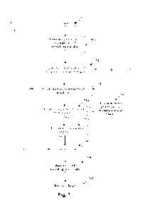
[0057] Fig. 7 is a flowchart illustrating a method 700 of intra-
stimulus ECAP detection and
feedback control in accordance with one embodiment of the present invention.
The method 700
may be carried out by the controller 116 as configured by the control programs
122. The method
700 starts at step 710, then proceeds to step 720, which commences the
delivery of stimulus
according to predefined stimulus parameters. Step 730 then records an ECAP
signal during at
least part of the stimulus delivery of step 720. Step 740 then checks whether
the ECAP intensity
(e.g. amplitude) in the recorded signal exceeds a threshold MAX which may
correspond to an
overstimulation threshold. If so, the method 700 proceeds to step 780 which
ceases the stimulus
commenced at step 720. In some embodiments, step 780 ceases the stimulus a
predetermined
time after observing that the ECAP recording has reached the threshold
amplitude at step 740.
[0058] If not, step 750 checks whether the ECAP intensity (e.g. the
instantaneous amplitude)
fails to reach a minimum threshold MIN. If so, step 760 revises one or more of
the stimulus
parameters, such as stimulus pulse current or voltage, to increase the
intensity of the stimulus
commenced at step 720. If not, the method 700 proceeds directly to step 770
which awaits the
expiry of a predefined stimulus duration. If the duration has not yet expired,
the method returns
to step 730 to continue recording the ECAP signal. Once the duration has
expired, step 780
ceases the stimulus commenced at step 720. Step 790 then waits for the ECAP
recording
commenced at step 730 to conclude, which may occur after a predefined delay
after ceasing the
stimulus. Step 795 then recovers any imbalance of charge that occurred as a
result of ceasing the
stimulus before the predefined duration had expired. Charge balancing may be
delivered by
delivering a stimulus pulse in a sub-threshold manner, or by active charge
recovery using a
charge recovery pulse of the same shape as the stimulus, or by using a charge
recovery pulse of
reduced amplitude and longer duration than the stimulus. Alternatively, charge
balancing may in
some embodiments be effected via passive charge recovery. Additionally or
alternatively,
charge balancing may in some embodiments be effected by delivering a cathodic
phase prior to
an anodic phase so that characteristics of both phases can be adjusted in
order to optimise neural
recruitment dose as well as maintain charge balancing.
CA 03207784 2023- 8-8
WO 2022/170388
PCT/AU2022/050080
18
[0059] In alternative embodiments, characteristics of the ECAP
other than instantaneous
amplitude may be determined and compared with one or more thresholds to
determine whether
to cease stimulus. In some embodiments, the characteristic is a binary
characteristic, such as a
presence or absence of an ECAP in the recording, that is, an indication as to
whether or not the
stimulus has recruited an ECAP. In another such embodiment, the at least one
characteristic may
comprise an indication that the ECAP in the recording has reached a threshold
amplitude. In
other embodiments, the at least one characteristic may comprise a gradated or
scalar indication
of an observed feature of the recording. The at least one characteristic of
the action potential may
comprise one or more of: a measure of ECAP onset delay time; a measure of ECAP
slope; an
averaged amplitude or trend line of the recording over two or more digital
samples; an ECAP
peak amplitude; a measure of ECAP duration such as ECAP peak width, ECAP zero
crossing
spacing, or ECAP half height width; a measure of ECAP spectral components such
as may be
obtained by fast Fourier transform (FFT) or the like. The at least one
characteristic of the ECAP
may comprise any such characteristic of a late response arising
contemporaneously with the
stimulus.
[0060] In some embodiments, recording of the neural compound action potential
signal may
cease upon detection that the ECAP intensity exceeds a threshold at step 740,
or when the
stimulus ceases at step 780, or at a time defined relative to such occasions.
Alternatively,
recording of the neural compound action potential signal may continue after
the step of defining
at least one characteristic of the stimulus (such as by ceasing the stimulus)
is completed, for
example in order to retrieve a lengthier recording of improved quality, for
use by secondary
processes such as a supervisory process providing feedback improvements of the
process for
determining the at least one characteristic of the evoked compound action
potential.
[0061] In some embodiments, defining or revising at least one
characteristic of the stimulus
based on the determined efficacy of the stimulus may comprise defining or
revising at least one
stimulus parameter in order to control the stimulus to deliver a desired dose
of neural
recruitment. For example, the at least one parameter may be adjusted in a
manner so as to
control the amount of charge delivered to the tissue by the stimulus For
example, a duration of
the stimulus may be adjusted on the basis of the determined efficacy of the
stimulus.
Additionally, or alternatively, an amplitude, intensity, voltage, current
and/or morphology of the
stimulus may be adjusted on the basis of the determined efficacy of the
stimulus.
CA 03207784 2023- 8-8
WO 2022/170388
PCT/AU2022/050080
19
[0062] In some embodiments, defining at least one characteristic of
the stimulus based on the
determined efficacy of the stimulus may comprise defining or revising a number
of pulses of the
stimulus. For example, based on the first controlled pulse, a series of
subsequent pulses may be
generated, wherein a relationship between the first and subsequent pulses may
be that a pulse
shape is identical, or that subsequent pulses decay in either pulse width or
amplitude at some rate
for a number N of pulses, or that subsequent pulses are different to the first
pulse but all the same
as each other.
[0063] Some embodiments may further provide for jointly considering
both (a) a during-
stimulation ECAP measurement, as in Fig. 7, and (b) at least one previous ECAP
measurement.
Such embodiments configure the stimulus based upon measurements of neural
activation
obtained in response to a previous stimulus. Such embodiments may for example
provide for
improved signal-to-noise-ratio (SNR) assessment of slowly changing stimulus
transfer function
characteristics, while also providing for rapid assessment of rapidly changing
stimulus transfer
function characteristics at a lower SNR. For example, when a patient coughs
such embodiments
may provide for a stimulus to be rapidly cut short upon detection of an
unexpected ECAP, even
if the detection has a poor SNR. Such embodiments may thus serve as a
supplemental function
to conventional closed loop control.
[0064] In some embodiments, measuring the neural response may be done on the
same
electrode on which the stimulation is delivered. That is to say that in such
embodiments, one or
more of the one or more stimulus electrodes also serve as one or more of the
one or more
recording electrodes. Such embodiments are advantageous in allowing for most
rapid detection
of any recruited neural response by eliminating any neural propagation delay,
noting that the
finite conduction velocity of neural responses necessarily results in the
neural response arising
on more distant electrodes at a later time.
[0065] In alternative embodiments, measuring the neural response may be
effected by way of
a sense electrode which is a non-stimulating electrode near the stimulus
electrode, as illustrated
in Fig. 3. To permit observation of a neural response to commence prior to
cessation of the
stimulus, the sense electrode(s) may be positioned at a distance from the
stimulus electrodes
which is less than 120 mm, preferably less than 100 mm, more preferably less
than 80 mm, and
CA 03207784 2023- 8-8
WO 2022/170388
PCT/AU2022/050080
most preferably less than 60 mm. The sense electrodes may be mounted on an
electrode lead
upon which the stimulus electrodes are mounted.
[0066] In some embodiments, measuring the neural response and
defining at least one
characteristic of the stimulus may be programmed to occur only at a certain
interval, amongst
periods of open loop operation or non-adaptive operation For example,
measuring the neural
response and defining at least one characteristic of the stimulus may be
triggered to occur based
on one or more factors, such as a physiological trigger, activity of the
patient or inputs from
other sensors such as an accelerometer.
[0067] Some embodiments invention may apply multi-phase stimulus
control, so as configure
a later phase of the stimulus based upon measurements of neural activation
obtained in response
to a previous phase of the stimulus.
[0068] In some embodiments, the measurement circuitry 128 may be blanked for
some
portion or portions of a period in which the stimulus crosstalk voltage
arises, whereby during
blanking some or all of the measurement circuitry 128 is disconnected from the
sense electrodes,
whereby during blanking an output of the measurement circuitry 128 does not
carry useful
measurement information but also does not suffer from stimulus crosstalk. For
example, the
measurement circuitry may be blanked during one or more stimulus transients,
referred to herein
as transient blanking. Transient blanking may be imposed during one or more of
an onset of a
stimulus phase and cessation of a stimulus phase, for one or more anodic
stimulus phase(s)
and/or for one or more cathodic stimulus phase(s). Transient blanking may be
imposed for
example for a period in the range of 10-50 jis either side of a stimulus
transient. Noting that a
stimulus phase width may be around 0.1 ¨ 1 ms, such embodiments may thus
provide for the
measurement circuitry to be unblanked for 80-95% of the duration of each
stimulus phase, while
being blanked to avoid exposure to stimulus transients, allowing for evoked
neural responses to
be observed for a significant portion of the stimulus period while avoiding
non-linearity, clipping
or saturation of the measurement circuitry.
[0069] To permit observation of a neural response to commence prior
to cessation of the
stimulus, the measurement circuitry 128 is preferably unblanked or activated
immediately
following a stimulus feature which is expected to cause neural activation,
such as the leading
CA 03207784 2023- 8-8
WO 2022/170388
PCT/AU2022/050080
21
edge of a cathodic portion of the stimulus. For example, the measurement
circuitry may be
unblanked or activated within 50 its, more preferably 20 is, more preferably
10 its, after such a
stimulus feature.
[0070] Some embodiments may provide for a stimulus protocol to be
applied whereby stimuli
are delivered at high frequency and low current, in which a single stimulation
is not expected to
elicit a neural response but the temporal summation of several stimulations is
intended to recruit
an ECAP. Such embodiments may provide for the stimulus protocol to be halted
once an ECAP
is observed or once the ECAP amplitude, peak width or other characteristic
reaches a threshold.
[0071] In some embodiments, the detection/measurement of the ECAP may be
carried out in
parallel on more than one recording electrode, to improve signal detection due
to the spatial and
temporal variations which will occur.
[0072] Some embodiments may provide for a stimulus intensity, such
as stimulus current
and/or stimulus voltage, to be progressively raised from a sub-threshold level
so as to search for
an ECAP recruitment threshold.
[0073] The neurom odul ati on may comprise spinal cord stimulation,
sacral nerve stimulation,
deep brain stimulation (DB S), vagus nerve stimulation, or other form of
neurom odul ati on .
[0074] The method may be applied in respect of a single stimulus
applied in isolation, or in
respect of multiple stimuli applied repeatedly, sporadically, or continuously,
such as at less than
Hz, at tens of Hz or at hundreds of Hz.
[0075] Some embodiments may comprise DBS monitoring of beta band
oscillations, whereby
the intra-stimulus response is measured continuously. For example DB S may be
applied at tens
or hundreds of Hz, and beta band oscillations variations may be computed and
compared to
changes of stimulus intensity or frequency or the like.
[0076] The stimulus may comprise a continuous or piecewise continuous
waveform, wherein
responses evoked by the continuous waveform can be used to adjust ongoing
application of the
waveform.
CA 03207784 2023- 8-8
WO 2022/170388
PCT/AU2022/050080
22
[0077] Fig. 8 illustrates the component waveforms as may arise in some
embodiments of the
invention. The signal on a recording electrode consists of a stimulus waveform
with passive
recovery (a) plus the ECAP (b) to give the composite waveform (c). Measuring
the neural
response may be done on the same electrode as is delivering the stimulation,
or may be done on a
nearby non-stimulating electrode. When the system detects the ECAP amplitude
reaches the
threshold (the feedback target), stimulation is ceased. The passive recovery
waveform allows the
system to automatically adjust for the varying pulse width of stimulation. An
active charge
recovery phase driven by a current source and providing matched charge could
also be used.
[0078] By leaving a gap between the stimulating and charge-recovery
pulses, the non-
overlapping part of the ECAP can be recorded without interference.
[0079] To illustrate the ability of recording ECAPs during
application of a stimulus, recording
was performed experimentally, in sequence, on each of a number of electrodes
of an electrode
array. The results are shown in Fig. 9. The biphasic stimulus pulse lasts for
approximately 1.8
ms with a phase transition at approximately 0.8 ms. The absence of data at
certain times in each
trace is because recording is suspended for approximately 70 [is at every
current transition in the
stimulus. No recordings were obtained for El or E2 (the stimulating
electrodes), nor E3, nor E7
(the reference electrode). This is in accordance with transient blanking as
described above.
[0080] Periods where the measurement circuitry prevented the
amplifier from recording input
are blanked in Fig. 9. The voltage arising on electrode E4 remains between
about +7001.1.V and -
1600 V, and is thus kept within the maximum input range of 2.4 mV by the
measurement
circuitry. All other recordings remain within an even smaller range. In
addition to the sinusoidal
signal of interest (injected to simulate ECAPs), some undesirable residual
stimulus artefact
remains on the electrodes, particularly E4 and E5, as seen in the decaying
excursions of these
recordings. However, as these unwanted artefact components are kept within the
input range of
the amplifier chain, such unwanted components can be removed digitally via DSP
techniques if
required. As desired, the 501..tV sinusoidal 4 kHz signal being used to
simulate ECAPs can be
observed and thus easily retrieved from all recordings. Indeed, for the
recordings from E6 and
E8-E12 the sinusoidal signal of interest can be directly resolved without
further processing,
during the first 2 ms of the plot, i.e. during application of the stimulus.
Characteristics of an
CA 03207784 2023- 8-8
WO 2022/170388
PCT/AU2022/050080
23
ECAP arising in this manner in such recordings can thus be extracted and
utilised to control or
alter application of the same stimulus.
[0081] Some embodiments of the present invention thus recognise
that an ability to record the
neural response during application of the stimulus can provide for single-
stimulus ECAP-
control 1 ed neuromodul ati on This may thus provide a method and device for
delivering a
stimulus to neural tissue, where the amplitude (or other characteristic(s)) of
the stimulus is
controlled by observing the neural response the stimulus pulse itself is
generating or has
generated.
[0082] It will be appreciated by persons skilled in the art that
numerous variations and/or
modifications may be made to the invention as shown in the specific
embodiments without
departing from the spirit or scope of the invention as broadly described. The
present
embodiments are, therefore, to be considered in all respects as illustrative
and not limiting or
restrictive.
Label list
spinal cord stimulator 100
electronics module 110
battery 112
telemetry module 114
controller 116
memory 118
patient settings 120
control programs 122
CA 03207784 2023- 8-8
WO 2022/170388
PCT/AU2022/050080
24
pulse generator 124
electrode selection module 126
measurement circuitry 128
amplifier 128a
digital converter 128b
analog controller 130
recording electrode array 150
nerve 180
transcutaneous communication 190
external device 192
period 402
stimulus 502
cathodic portion 504
time 506
first ECAP recording 508
ECAP amplitude 510
stimulus 522
CA 03207784 2023- 8-8
WO 2022/170388
PCT/AU2022/050080
amplitude 525
second recording 52g
third stimulus 542
time 610
time 620
neural response 625
amplitude 630
stimulus cessation time 640
method 700
step 710
step 720
step 730
step 740
step 750
step 760
step 770
step 780
CA 03207784 2023- 8-8
WO 2022/170388
PCT/AU2022/050080
26
step 790
step 795
CA 03207784 2023- 8-8