Note: Descriptions are shown in the official language in which they were submitted.
Description
Title of Invention
THERMOSTAT DEVICE
Technical Field
[0001]
The present invention relates to a thermostat device
disposed in the middle of a circulation flow passage through
which a coolant is circulated between an internal combustion
engine (hereinafter also referred to as an engine) and the
radiator mounted on automobiles, for example, to control the
coolant temperature appropriately.
Background Art
[0002]
The thermostat device is provided with a thermo-
element incorporating a thermal expansion body (wax)
expanding and contracting by sensing a temperature change
in the coolant flowing through the circulation flow passage
between the engine and the radiator and functions to
maintain the coolant to a predetermined temperature by
opening and closing the control valve (valve body) by
1
CA 03208751 2023- 3- 16
volume change caused by expansion and contraction of the
thermal expansion body.
[0003]
Namely, a thermo-operating unit, including a thermo-
element incorporating a thermal expansion body and a
control valve, is accommodated in a housing and, for
example, disposed at the inlet of the coolant passage of
the engine. The thermo-operating unit closes the valve
when the coolant temperature is low, and the coolant is
circulated through the bypass passage without passing
through the radiator.
Further, the thermo-operating unit opens the valve to
have the coolant circulate through the radiator when the
coolant temperature increases. With this, the thermo-
operating unit operates to control the temperature of the
coolant through the water jacket, which is the coolant
passage in the engine, to a proper state.
[0004]
Therefore, for a thermostat device of this type,
improving the temperature sensitivity capable of
immediately responding to the coolant temperature from the
engine and controlling open and close of a control valve is
required. A thermostat device disclosed in patent
literature 1 (PTL 1) is an example thereof.
2
CA 03203751 2023- 3- 16
The thermostat device illustrated in PTL 1 is shown
in Fig. 13. The thermostat 11 is constituted by
accommodating the thermo-operating unit 15 in a housing 12
composed of a case 13 and an inlet 14.
[0005]
A flow inlet 14a of the coolant from the radiator side
is formed on the inlet 14 side, constituting the housing 12.
In the case 13 side, constituting the housing 12 similarly,
a flow inlet 13a of the coolant from the bypass passage
bypassing the radiator and a flow inlet 13b of the coolant
through the heater core as a heat exchanger for cabin heating
are formed. The coolant from respective flow inlets 13a,
13b, and 14a are mixed in the housing 12 and delivered toward
the water jacket of the engine through the flow outlet 13c
of the coolant.
[0006]
The thermo-operating unit 15 includes a thermo-element
(temperature sensing unit) 15a incorporating a thermally
expanding body (wax) responding to the coolant temperature,
a piston 15b extending and retracting by the action of the
thermally expanding body, a disc-shaped control valve (valve
body) 15c attached to the thermo-element 15a,a spring member
15d biasing the control valve 15c to abut on the inlet 14
side to be into the closed-valve state.
3
CA 03203751 2023- 3- 16
The tip end of the piston 15b is engaged with a shaft
supporting part 14b formed in the inlet 14.
The valve
opening state of the control valve 15c is controlled
depending on the coolant temperature applied to the thermo-
element 15a. Thus, the thermo-operating unit 15 operates to
keep the coolant temperature applied to the engine to be
appropriate by adjusting the flow-in amount of the coolant
from the radiator side in particular.
[0007]
Further, in the thermostat device 11 disclosed in PTL
1, a cylindrical member 16 surrounding the cylindrical
thermo-element 15a and having a predetermined gap to the
thermo-element 15a is disposed, attached inside the case 13.
With the cylindrical member 16, the coolant from the bypass
passage is configured to flow along the circumference of the
thermo-element 15a. It is recited that in this configuration
the thermo-element 15a controls the valve-opening state of
the control valve 15 depending on the coolant temperature
from the bypass passage, and a thermostat device having an
excellent temperature sensitivity corresponding to the
coolant temperature from the engine can be provided.
Citation List
Patent Literature
4
CA 03203751 2023- 3- 16
[0008]
PTL 1: W02007-108273
Summary of Invention
Technical Problem
[0009]
In the thermostat device 11 disclosed in PTL 1, the
coolant from the bypass passage is directed toward the flow
outlet 13c side of the coolant through the gap between the
thermo-element 15a and the cylindrical member 16.
Thus, there is a technical problem that it is difficult
to ensure the flow amount when the flow amount from the
bypass passage bypassing the radiator increases due to the
squeeze of the flow of the coolant in the gap between the
thermo-element 15a and the cylindrical member 16.
[0010]
The present invention is made considering the
technical problems of conventional thermostat devices, and
it is a main task to provide a thermostat device that can
ensure a sufficient flow amount of coolant from the bypass
passage and also have an excellent temperature sensitivity
corresponding to the temperature of the coolant from the
engine.
CA 03203751 2023- 3- 16
Solution to problem
[0011]
A thermostat device according to the present invention
made in order to solve the above-described problems includes,
as recited in claim 1,
a housing provided with
a first flow inlet to introduce a coolant that is
cooled by a radiator,
a second flow inlet to introduce a heated coolant by
an internal combustion engine not passing through the
radiator, and
a flow outlet of the coolant to deliver the coolant to
the internal combustion engine which is a mixture of
respective coolants from the first flow inlet and the second
flow inlet;
a thermo-element accommodated in the housing and axially
movable depending on the temperature of the coolant from the
second flow inlet;
a control valve that controls the introduced amount of the
coolant from the first flow inlet upon the movement of the
thermo-element;
multiple guides formed to extend toward the thermo-element
from the second flow inlet side and disposed intermittently
along the circumference of the thermo-element, supporting
6
CA 03203751 2023- 3- 16
the thermo-element axially movably;
coolant rectifying protrusions arrayed with a gap from the
thermo-element at the positions avoiding the guides on the
circumference of the thermo-element; and
detoured passages of the coolant directing from the second
flow inlet side to the flow outlet side, formed between the
adjacent guides and the coolant rectifying protrusions,
between the guides, or between the coolant rectifying
protrusions.
[0012]
According to the invention as recited in claim 1, at
the second flow inlet side for introducing coolant heated at
the internal combustion engine but not passing through the
radiator, multiple guides are intermittently disposed along
the circumference of the thermo-element constituting the
thermo-operating unit, and the thermo-element is supported
by the guides movably in the axial direction. This structure
allows the thermo-element to move smoothly along the axial
direction and ensures the reliability of the operation of
the thermo-operating unit.
[0013]
Further, the coolant rectifying protrusions are formed
with space apart from the thermo-element between the guides
supporting the thermo-element.
The coolant rectifying
7
CA 03208751 2023- 3- 16
protrusions allow part of the coolant from the second flow
inlet to flow along the thermo-element between the coolant
rectifying protrusions and the thermo-element. Therefore,
the thermo-element efficiently reacts to the coolant
temperature from the second flow inlet and performs open-
close control of the control valve, and contributes to
improving the temperature sensitivity of the thermo-
operating unit.
[0014]
Further, since a detoured passage for coolant flowing
from the second flow inlet side to the flow outlet is formed
by forming gaps between the guides and coolant rectifying
protrusions, both arrayed along the periphery, between
guides, and between the coolant rectifying protrusions, the
coolant from the second flow inlet is the sum of coolant
flowing in the detoured passage formed by the gaps and the
amount of coolant flowing between the thermo-element and the
coolant rectifying protrusions. This structure can provide
a thermostat device that can sufficiently ensure the amount
of coolant from the second flow inlet.
[0015]
Further, in the preferable embodiment of the
thermostat device according to the present invention, as
recited in claim 2, the thermo-element is formed to be
8
CA 03203751 2023- 3- 16
cylindrical, disposed in a state where the guides are
slidably in contact with the side face of the thermo-element
at least at three positions along the circumference of the
thermo-element, and in addition, the length of the respective
guides along the axial direction of the thermo-element is
formed longer than the length of the coolant rectifying
protrusions.
[0016]
According to the invention recited in claim 2, the
length of the respective guides along the axial direction of
the thermo-element is formed longer than the length of the
coolant rectifying protrusions, whereby the guides can cover
the movement range of the lower bottom side of the thermo-
element.
Thus, the guides effectively prevent the radial run-
out particularly near the lower bottom portion of the thermo-
element moving in the axial direction, whereby a smooth
motion along the axial direction of the thermo-element can
be achieved.
[0017]
In contrast, in the thermostat device according to the
present invention, as recited in claim 3, the end portion of
each guide of the second flow inlet side is located closer
to the second flow inlet side than the coolant rectifying
9
CA 03203751 2023- 3- 16
protrusions, and a coolant passage from the second flow inlet
side to the flow outlet is preferably formed between the
respective guides in a state where the thermo-element moves
most to the second flow inlet side.
[0018]
According to the invention recited in claim 3, a
coolant passage from the second flow inlet side to the flow
outlet is formed between the respective guides in a state
where the thermo-element moves most to the second flow inlet
side.
Since the passage allows a low flow rate of coolant to
flow from the second flow inlet side to the flow outlet even
in the case the thermo-element moves lower than the case
inner bottom to open the control valve widely, the supply
amount of coolant to the engine is secured.
[0019]
Further, in the thermostat device according to the
present invention, in addition to the above construction, as
recited in claim 4, the coolant rectifying protrusions are
disposed along the axial direction of the thermo-element.
[0020]
According to the invention recited in claim 4, since
the coolant rectifying protrusions are arrayed along the
axial direction of the thermo-element, the coolant
CA 03203751 2023- 3- 16
rectifying protrusions make the coolant flow along the
longitudinal direction of the coolant rectifying protrusions
and provide effects to bring the coolant into effective
contact with the thermo-element.
This can provide a thermostat device with excellent
temperature sensitivity corresponding to the coolant
temperature.
Advantageous Effects of Invention
[0021]
According to the present invention, a thermostat
device ensuring a sufficient amount of coolant from the
bypass passage and also having an excellent temperature
sensitivity corresponding to the temperature of the coolant
from the engine can be provided.
Brief Description of Drawings
[0022]
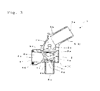
Fig. 1 is a front view showing the entire configuration
of a thermostat device according to the present invention;
Fig. 2 is a partial cross-sectional view shown by
cutting away the front half of a housing shown in Fig. 1;
Fig. 3 is a partial cross-sectional view shown by
11
CA 03203751 2023- 3- 16
cutting away the right half of the housing, viewed from the
cutting side;
Fig. 4 is a perspective view showing the entire
configuration of the thermostat device;
Fig. 5 is a perspective view showing the top-bottom
inverted from the state shown in Fig. 4;
Fig. 6 is a plan view of the thermostat device viewed
from the center of the housing toward the second flow inlet
side;
Fig. 7 is a partially enlarged view illustrating the
relation between the second flow inlet and the thermo-
element;
Fig. 8 is a schematic view of the thermostat device in
the process of assembly;
Fig. 9 is a partially enlarged view of the thermostat
device viewed from an assembly jig side shown in Fig. 8;
Fig. 10 is an enlarged view of part A in the schematic
view shown in Fig. 8;
Fig. 11 is a partially enlarged view of coolant flow
passing through the detoured passage of the coolant;
Fig. 12 is a partially enlarged view of the flow of
the coolant due to coolant rectifying protrusions; and
Fig. 13 is a cross-sectional view of an example of a
conventional thermostat device.
12
CA 03203751 2023- 3- 16
Description of Embodiments
[0023]
A thermostat device according to the present invention
will be described based on embodiments illustrated in
drawings. Figs. 1 through 5 show the entire configuration
of the thermostat device.
The thermostat device 1 is
disposed in a circulation passage for circulating the coolant
between the engine and the radiator and is constituted by
accommodating the thermo-operating unit 2 which controls the
temperature of the coolant to be supplied to the engine in
the housing 3.
[0024]
That is, the thermostat device 1 is disposed at a
crossing section of a coolant passage from the radiator side
and a bypass passage for coolant from an outlet side of the
engine not passing through the radiator. The thermostat
device 1 operates to appropriately control the temperature
of the coolant toward an inlet of the engine by mixing a
coolant that is cooled at the radiator and a coolant from
the bypass passage heated at the engine.
[0025]
For the convenience of description, the upper portion
and the lower portion in Fig. I are simply referred to as
13
CA 03208751 2023- 3- 16
"the upper" and "the lower" from now. In the embodiment,
the housing 3 constituting an outer frame of the thermostat
device 1 is composed of a case 4 and an inlet 5 joined and
attached to the top of the case 4, both molded of a resin
material.
The inlet 5 is provided with a first flow inlet 5a
having a cylindrical shape for receiving the coolant from
the radiator side; the first flow inlet 5a is formed in a
state of being bent by about 60 degrees (See Fig. 3) with
respect to the axis of movement of the thermo-operating unit
2 described later.
A unit housing space 4a of the thermo-operating unit
2 is formed in the center part of the case 4, and a
cylindrical second flow inlet 4b is formed directing downward
from the unit housing space 4a, and the coolant from the
bypass passage is introduced to the second flow inlet 4b.
[0026]
Further, in the case 4, a flow outlet 4c of the coolant
for supplying the coolant to the engine side is formed toward
the direction orthogonal to the axis of movement of the
thermo-operating unit 2, and the flow outlet 4c of the
coolant is formed toward the opposite side to the bending
direction of the first flow inlet 5a formed in the inlet 5
(See Fig. 3.)
14
CA 03203751 2023- 3- 16
[0027]
The flow outlet 4c of the coolant is constituted
enabling it to be disposed on the upstream side of the water
pump for delivering the coolant to the engine; for this
purpose, a flange 4d for directly connecting the thermostat
device 1 to the water pump (not shown) side and bolt
insertion holes 4e (See Figs. 4 and 5) for fastening bolts
at positions opposite to each other by 180 degrees are
provided on the flange 4d. In addition, an annular-shaped
packing 4f for joining to the water pump side is attached
along the opening so as to surround the flow outlet 4c of
the coolant.
[0028]
The thermo-operating unit 2 accommodated in the unit
housing space 4a of the housing 3 is provided with a
cylinder-shaped thermo-element (temperature sensing unit) 2a
incorporating a thermal expansion body (wax) that expands
and contracts depending on the coolant temperature; the
piston 2b disposed along the axis of the thermo-element 2a
operates to advance and retract from the thermo-element 2a
due to the expansion and contraction of the thermal expansion
body.
The tip portion of the piston 2b is fitted to a shaft
support 5b formed at the central upper portion inside the
CA 03203751 2023- 3- 16
inlet 5 constituting the housing 3 and attached to the
housing 3.
Accordingly, the cylinder-shaped thermo-element 2a
operates to move along the axial direction in the unit
housing space 4a as the piston 2b extends and retracts.
[0029]
A disc-shaped control valve (valve body) 2c is attached
to the upper portion of the thermo-element 2a, and the
control valve 2c creates a valve-closed state by abutting on
an annular valve seat 5c formed at the lower opening of the
inlet 5. A spring member 2d is disposed surrounding the
thermo-element 2a so as to be in contact with the control
valve 2c at one end thereof, and, in the case 4, the other
end of the spring member 2d abuts the case inner bottom 4j
of the case 4 so as to surround the guides 4g intermittently
annularly arrayed and the coolant rectifying protrusions 4h
(See Figs 6 and 7).
Accordingly, the spring member 2d applies a biasing
force so as to press the disc-shaped control valve 2c to the
annular valve seat 5c formed in the inlet 5.
[0030]
The guides 4g and the coolant rectifying protrusions
4h, also shown in Figs. 6 and 7, are formed to respectively
rise from the second flow inlet 4b side of the case 4 toward
16
CA 03208751 2023- 3- 16
the unit housing space 4a.
Of these, the guides 4g are formed to extend from the
second flow inlet 4b side toward the thermo-element 2a and,
in this embodiment, are arrayed at an interval of 120 degrees
along the periphery of the thermo-element 2a. That is, the
axially-long inscribed surfaces of the three guides 4g are
in sliding contact with the side surface of the thermo-
element 2a and function to support the thermo-element 2a
movably in the axial direction.
[0031]
The upper end of the guides 4g locates at a higher
position than the upper end of the coolant rectifying
protrusions 4h. Further, the guides 4g are formed to cover
the range of movement of the lower bottom part side of the
thermo-element 2a so as to further reach the second flow
inlet 4b side than the case inner bottom 4j, as shown in Fig.
7.
Because of this, the length of the guides 4g along the
axial direction of the thermo-element 2a is formed longer
than the length of the coolant rectifying protrusions 4h.
The guides 4g effectively prevent the radial run-out
particularly near the lower bottom portion of the thermo-
element 2a moving in the axial direction, whereby a smooth
motion along the axial direction of the thermo-element 2a
17
CA 03203751 2023- 3- 16
can be achieved.
[0032]
The coolant rectifying protrusions 4h are arranged at
equal intervals in the circumferential direction between
each of the three guides 4g. That is, the three coolant
rectifying protrusions 4h rise from the case inner bottom 4j
of the case as shown in Fig. 7, and the upper end thereof is
formed to locate at a position slightly lower than the upper
end of the guide 4g.
The coolant rectifying protrusions 4h are disposed
with a predetermined gap with respect to the side surface of
the thermo-element 2a. It is desirable that the gap between
the side surface of the thermo-element 2a and the coolant
rectifying protrusions 4h is set to be 1 mm or wider.
Each coolant rectifying protrusion 4h provides the
action of effectively bringing the flow of coolant from the
second flow inlet 4b into contact with the thermo-element 2a
along the longitudinal direction of the coolant rectifying
protrusions 4h.
[0033]
A gap 4i is formed at the upper position of the case
inner bottom 4j of the case 4 between the guides 4g and the
coolant rectifying protrusions 4h, as shown in Figs. 3 and
6. The gap 4i functions as a detoured passage (indicated by
18
CA 03203751 2023- 3- 16
the same reference sign 41) of the coolant from the second
flow inlet 4b side toward the flow outlet 4c of the coolant.
The functions and the effects of this coolant detoured
passage 4i will be described later.
[0034]
The end portion of the second flow inlet 4b side of
each guide 4g locates at a closer position to the second
flow inlet 4b than the coolant rectifying protrusion 4h as
shown in Fig. 7. In a state where the valve opening of the
control valve 2c increases to cause the thermo-element 2a to
move below the case inner bottom 4j, an arc-shaped flow
passage 4k with the thermo-element 2a as an inner
circumferential surface is formed between each guide 4g, as
shown in Fig. 6.
The arc-shaped flow passage 4k allows a low flow rate
of coolant to flow from the second flow inlet 4b side toward
the flow outlet of the coolant even when the control valve
2c opens widely by the movement of the thermo-element 2a
downward below the case inner bottom 4j, whereby the supply
amount of coolant to the engine can be secured.
[0035]
Figs. 8 through 10 show the assembly procedure of the
thermostat device 1.
At the time of assembly of the
thermostat device 1, a supporting member of the thermo-
19
CA 03203751 2023- 3- 16
element formed columnar is prepared as an assembly jig 7.
The assembly jig 7 is constructed based on an
equilateral triangular prism having a configuration in which
the ridges forming the three interior angles of an
equilateral triangular prism are each formed into an arc
shape; the shape viewed from the lowest end side of the
longitudinal direction is illustrated in Fig. 9.
Each
surface formed arc-shaped is formed to have a dimension to
inscribe with the second flow inlet 4b of the case 4 and the
coolant rectifying protrusion 4h, as shown in Fig. 8.
[0036]
In addition, the assembly jig 7 has an axial bore 7a
along the axis, and, on the upper end thereof, a small
protrusion 7b protruding from the arc-shaped end face is
formed, as shown in the partially enlarged view in Fig. 10
(corresponding to the A-portion in Fig. 8). The arc-shaped
small protrusion 7b, with inscribing with the bottom
circumferential surface of the thermo-element 2a, is
configured such that the thermo-element 2a can be placed on
the upper end of the assembly jig 7.
[0037]
The assembly jig 7 formed in columnar is inserted from
the second flow inlet 4b side of the case 4, as shown in Fig.
8. At this time, as shown in Fig. 9, the assembly jig 7 is
CA 03203751 2023- 3- 16
inserted from the second flow inlet 4b such that the face 7c
of the square prism of the assembly jig 7 is positioned at
the guides 4g formed in the case 4; that is, the arc-shaped
face of the assembly jig 7 may not come in to contact with
the guides 4g.
Subsequently, the spring member 2d is
attached along the periphery of the assembly jig 7 protruding
upward from the case 4.
[0038]
By placing the thermo-element 2a, to which the control
valve 2c is attached in advance, on the top of the spring
member 2d and pressing it along the axial direction, the
bottom portion of the thermo-element 2a is axially aligned
with the assembly jig 7 using the small protrusion 7b as the
guide as shown in Fig. 10 and brought into contact with the
upper end of the assembly jig 7. Then, the thermo-element
2a is adsorbed to the upper end of the assembly jig 7 and
temporally fixed, by applying negative pressure through the
axial bore 7a of the assembly jig 7.
[0039]
The tip portion of the piston 2b formed in the thermo-
element 2a is inserted into the shaft support 5b of the inlet
in a state where the thermo-element 2a is temporally fixed
on the upper-end face of the assembly jig 7.
In the above state, the thermo-element 2a is
21
CA 03203751 2023- 3- 16
accommodated in the central portion of annularly arrayed
guides 4g and the coolant rectifying protrusions 4h by
pulling out the assembly jig 7 from the second flow inlet 4b
while pressing the inlet 5 to the case 4 side.
At last, the assembly of the thermostat device 1 is
completed by joining the inlet 5 on the case 4.
[0040]
According to the assembly means for the thermostat
device 1 using the assembly jig 7, described based on Figs.
8 to 10, by inserting the assembly jig 7 into the second
flow inlet 4b and mounting the thermo-element 2a on the
assembly jig 7, the thermo-element 2a can be pulled into the
inside of the guides 4g and the coolant rectifying
protrusions 4h in a state where the thermo-element 2a is put
centered by aligning the center of the thermo-element 2a
with the center of the annularly arrayed guides 4g and the
coolant rectifying protrusions 4h which are disposed
surrounding the second flow inlet 4b.
With this, the thermo-element 2a can be surely inserted
inside the guides 4g and the coolant rectifying protrusions
4h without tilting the spring member 2d during assembly.
Thus, since the thermo-element 2a can be surely
inserted inside the guides 4g and the coolant rectifying
protrusions 4h while preventing the spring member 2d from
22
CA 03208751 2023- 3- 16
tilting, it is possible to assemble the thermostat device 1
by an automatic machine.
[0041]
The assembly procedure of the thermostat device 1 is
not limited to this, but can be appropriately changeable.
For example, the thermostat device I can be assembled
manually. In such a case, the shape of the conduit on the
bypass passage side, where the second inlet 4b is formed,
may be straight, as shown in the drawings, or even if it is
L-shaped or any other shape, the thermostat device 1 can be
assembled.
That is, the shape of the conduit on the bypass passage
side, where the second flow inlet 4b is formed, may be
straight, L-shaped, or in any other shape.
[0042]
According to the thermostat device I thus constituted
above, the coolant supplied to the second flow inlet 4b from
the bypass passage side is supplied to the unit housing space
4a of the housing 3 where the thermo-element 2a is located
therein. When the temperature of the coolant from the bypass
passage side rises there, the expansion body incorporated in
the thermo-element 2a expands and the piston 2b extends
(protrudes).
This movement causes the control valve 2c attached to
23
CA 03203751 2023- 3- 16
the thermo-element 2a to retract toward the second flow inlet
4b side to open the valve, resisting the biasing force of
the spring member 2d, and the coolant having passed through
the radiator from the first flow inlet 5a is supplied.
Accordingly, the coolant from the first flow inlet 5a
and the coolant from the second flow inlet 4b are mixed in
the vicinity of the unit housing space 4a, and the mixture
is delivered to the water jacket of the engine from the flow
outlet 4c of the coolant. This allows the temperature of
the coolant through the engine water jacket to be controlled
to a proper state.
[0043]
Further, as shown in Figs. 6 and 7, in the thermostat
device I described above, the thermo-element 2a is supported
movably in the axial direction by the three guides 4g
disposed at an equal distance along the periphery of the
thermo-element 2a. This allows the thermo-element 2a to
move along the axial direction smoothly and ensures the
reliability of the operation of the thermo-operating unit 2.
[0044]
In addition, in the embodiment, three coolant
rectifying protrusions 4h allowing the coolant supplied to
the second flow inlet 4b through the bypass passage to flow
along the thermo-element 2a are disposed between the guides
24
CA 03203751 2023- 3- 16
4g. This allows part of the coolant from the second flow
inlet 4b to flow along the longitudinal direction of the
coolant rectifying protrusions 4h, as indicated by an arrow
extending toward B direction in Fig. 11.
As a result, the thermo-element 2a efficiently reacts
to the coolant temperature from the second flow inlet 4b and
allows to control opening and closing of the control valve
2c, thereby contributing to the improvement of the
temperature sensitivity of the thermo-operating unit 2.
[0045]
Further, in the embodiment, since between the guides
4g and the coolant rectifying protrusions 4h, both arrayed
along the periphery of the thermo-element 2a, a gap 4i is
formed to form a detoured passage 4i for the coolant toward
the flow outlet 4c from the second flow inlet 4b, the coolant
from the second flow inlet 4b is allowed to flow efficiently
through the detoured passage 4i formed by the gap, as
indicated by an arrow extending to C direction in Fig. 12.
Accordingly, in the coolant from the second flow inlet
4b, the flow indicated by arrow C in Fig. 12 is added to the
flow indicated by arrow B in Fig. 11, thereby providing the
thermostat device 1 capable of ensuring the coolant flow
amount through the bypass passage sufficiently.
[0046]
CA 03203751 2023- 3- 16
In the embodiment described above, three guides 4g are
provided at an equal interval along the circumferential
direction; four or more guides can be provided as needed and
may also be provided at unequal intervals along the
circumferential direction.
Further, one coolant rectifying protrusion 4h is each
disposed between the respective guides 4g, but two or more
coolant rectifying protrusions may be disposed; the number
thereof may be set optionally depending on the positions of
the flow outlet 4c of the coolant.
Accordingly, the gap 4i constituting the detoured
passage of the coolant may be formed between adjacent guide
4g and the coolant rectifying protrusion 4h, between the
guides 4g or between the coolant rectifying protrusions 4h,
depending on the arrangement of the guides 4g and the coolant
rectifying protrusions 4h.
Industrial Applicability
[0047]
As described above, the thermostat device according to
the present invention is useful as a device for supplying
coolant to an engine of an automobile and is particularly
suitable for use in controlling the temperature of coolant
supplied to the engine to a proper state.
26
CA 03203751 2023- 3- 16
Reference Signs List
[0048]
1 Thermostat device
2 thermo-operating unit
2a thermo-element
2b piston
2c control valve (valve body)
2d spring member
3 housing
4 case
4a unit housing space
4b second flow inlet
4c flow outlet
4d flange
4e bolt insertion hole
4f packing
4g guide
4h coolant rectifying protrusion
41 gap (detoured passage of coolant)
4j case inner bottom
4k flow passage
inlet
5a first flow inlet
27
CA 03208751 2023- 3- 16
5b shaft support
5c valve seat
28
CA 03203751 2023- 3- 16