Note: Descriptions are shown in the official language in which they were submitted.
LORENZ & KOLLEGEN
MC15077P/EP
Rail arrangement, carrier arrangement and fiber-optic distribution system
The invention relates to a rail arrangement for a carrier unit for a fiber-
optic component,
in particular for a patch panel, having a first mounting rail and a separate
second
mounting rail.
The invention also relates to a carrier arrangement, having a carrier unit, in
particular a
patch panel, and a rail arrangement for the carrier unit.
The invention furthermore relates to a fiber-optic distribution system, having
a
distribution frame and a plurality of carrier arrangements.
In data centers, carrier units, in particular individual trays up to what are
referred to as
patch panels are sometimes used for producing and distributing data
connections, for
example via network cables, telephone cables or glass fiber cables. A patch
panel of
this type generally comprises at least one interface with a certain number of
individual
connectors or plug-in connectors or same grouped in cassettes. In practice, a
plurality
of patch panels are frequently installed in different height positions in a
common
distribution frame, or rack.
For reasons of accessibility to the interfaces of the patch panel for a
service engineer,
the patch panels or trays can frequently be extended out of the distribution
frame as
required and, for this purpose, are fastened together with a correspondingly
configured
.. carrier housing, or chassis, in the distribution frame, as described, for
example, in US
2022/0236510 Al. The carrier housing is mounted rigidly on the distribution
frame and
has suitable linear pull-out mechanisms for the trays. In order to further
increase the
connector density, a plurality of patch panels are generally arranged in a
common
carrier housing.
For reasons of standardization endeavors and as high a degree of modularity as
possible, only a limited number of height variants is provided for such
carrier housings.
Furthermore, the carrier housings can be mounted in the distribution frame
only at a
discrete spacing ¨ as a multiple of what is referred to as a height unit (U).
Arbitrary
Date Recue/Date Received 2023-08-09
-2-
height scalability is not possible, and therefore storage space in the
distribution frame
can often not be optimally used. Furthermore, the diversity of configurations
is limited
and the generally closed carrier housings also provide only restricted access
to the
patch panels from the rear side and from above.
This is the starting point of an embodiment of the invention.
In view of the known prior art, it is the object of an embodiment of the
present invention
to provide a rail arrangement for a carrier unit for a fiber-optic component,
in particular
for a patch panel, with which the storage space in a distribution frame can be
better
utilized, with simultaneously good accessibility for a service engineer, and
with which
preferably also the diversity of configurations for carrier units in a common
distribution
frame can be increased.
In an embodiment, the present invention is also based on the object of
providing an
improved carrier arrangement and a fiber-optic distribution system, with
preferably high
connector density, good accessibility for a service engineer, and a great
diversity of
configurations.
The object is achieved for the rail arrangement having the features set out as
follows: A
rail arrangement for a carrier unit for a fiber-optic component, in particular
for a patch
panel, having a first mounting rail and a separate second mounting rail,
wherein the
mounting rails are spaced apart from each other and are designed to jointly
receive the
carrier unit between them, and wherein each of the mounting rails has at least
one
fastening point for fastening to a distribution frame.
In terms of the carrier arrangement, the object is achieved by a carrier
arrangement as
follows: a carrier arrangement, having a carrier unit, in particular a patch
panel, and a
rail arrangement for the carrier unit as follows: A rail arrangement for a
carrier unit for a
fiber-optic component, in particular for a patch panel, having a first
mounting rail and a
separate second mounting rail, wherein the mounting rails are spaced apart
from each
other and are designed to jointly receive the carrier unit between them, and
wherein
each of the mounting rails has at least one fastening point for fastening to a
distribution
frame, wherein the carrier unit is received between the two mounting rails.
The object
is achieved in relation to the fiber-optic distribution system, by a fiber-
optic distribution
Date Recue/Date Received 2023-08-09
-3-
system, having a distribution frame and a plurality of the aforementioned
carrier
arrangements, which are fastened in the distribution frame, preferably are
fastened in
different height positions. The features described below relate to
advantageous
embodiments and variants of the invention.
A rail arrangement for a carrier unit for a fiber-optic component is provided,
in particular
for a patch panel or a tray, having a first mounting rail and a separate
second mounting
rail. The mounting rails are spaced apart from one another and are designed to
jointly
receive the carrier unit between them.
The carrier unit preferably has at least one fiber-optic component (or at
least provides
the possibility of receiving a fiber-optic component) and can be received
movably or
immovably or rigidly between the mounting rails. The rail arrangement can be
designed
in particular to guide the carrier unit movably along at least one degree of
freedom (in
particular along at least one translation degree of freedom) and/or to provide
a
fastening or depositing option, for example the supporting surface also
mentioned
below, for the carrier unit.
The rail arrangement can be suitable in principle for all known and future
carrier units.
In an embodiment, the invention can be particularly advantageously suitable
for use
with optical trays or patch panels, optionally also for use with optical-
electrical trays or
patch panels. A tray or patch panel includes optical and/or electrical
distribution
technology and can have, for example, individual fiber-optic and/or electrical
modules or
cassettes, individual fiber-optic and/or electrical plug-in connectors (in
particular
sockets), devices for storing fiber-optic and/or electrical conductors and
lines or other
optical and/or electrical components. The carrier unit can also be designed
only for
purely receiving or depositing/storing and/or for splicing lines. Even dummy
carrier units
or dummy patch panels can be provided, for example having front plates which
are
intended exclusively to meet an informative purpose, such as labeling panels,
or to be
in the form of spacers.
The "first mounting rail" and the "second mounting rail" are also sometimes
jointly
referred to below as "mounting rails".
Date Recue/Date Received 2023-08-09
-4-
It is preferably provided that the mounting rails of the rail arrangement are
components
which are independent of one another and which, even in the mounted state, are
not
connected to one another ¨ apart from the joint connection to the carrier unit
and the
joint connection to the distribution frame. In particular, additional
connecting struts or
connecting plates between the two mounting rails of a joint rail arrangement
can be
dispensed with.
The mounting rails can in each case be formed integrally. However, a mounting
rail may
also be a multi-part component.
In the multi-part case which is in principle preferred, provision can be made
in particular
that the mounting rails each have at least one profile rail and at least one
functional
component connected to the profile rail or to the profile rails. The
functional component
is preferably arranged on that side of the mounting rail which faces the
carrier unit and
has components directly interacting with the carrier unit (e.g. the movement
limiting
means also mentioned below, etc.). The profile rail can be used as a carrier
for the
functional component.
The functional component can be designed as a stabilizing rail for the profile
rail. In
particular in this case, the functional component and the profile rail are
connectable to
one another (preferably directly), in a mechanically rigid manner (in a force-
fitting, form-
fitting and/or integrally bonded manner), in particular are latchable to one
another. For
this purpose, the profile rail can have one or more connecting elements (e.g.
a latching
recess or an offset) and the functional component can have corresponding
connecting
elements (e.g. one or more elastic latching elements). However, a movable
fastening
between profile rail and functional component can also be provided (in
particular along
or counter to the insertion direction also mentioned below), and therefore the
functional
component can be used, for example, as a pull-out mechanism to which the
carrier unit
is connected (in particular directly) in a mechanically rigid manner.
The mounting rails can be formed from a metal component or can at least have
metallic
components. In particular, the profile rail can be formed from a metal
component. For
example, the mounting rails, in particular profile rails, can have formed
sheet metal
parts or can be designed as formed sheet metal parts and produced, for
example,
within the scope of a punching and bending process.
Date Recue/Date Received 2023-08-09
-5-
The mounting rails, in particular the functional components, can also be
formed from a
plastic or can at least have plastics components. For example, comparatively
complex
functional features can be produced cost-effectively and with a high degree of
accuracy
and low component weight within the scope of an injection molding process.
Alternatively, however, the configuration of the functional components as a
sheet metal
part can also be provided.
The two mounting rails preferably run parallel or at least substantially
parallel to one
another along their longitudinal extents or longitudinal axes.
The two mounting rails are preferably spaced apart from one another along a
first
translation degree of freedom (corresponding to the width of the rail
arrangement). A
second translation degree of freedom preferably defines the insertion and
extension
direction, also mentioned below, for the carrier unit (corresponding to the
overall depth
of the rail arrangement). The overall height of the rail arrangement is
preferably
assigned to a third translation degree of freedom. Said three translation
degrees of
freedom are in each case oriented orthogonally to one another according to the
customary definition.
In a minimalistic embodiment, the rail arrangement can comprise, for example,
two L-
shaped profile rails which form the mounting rails and which can be mounted
independently of one another and without mutual connection on the supports of
a
distribution frame.
L-shaped profile rails can be particularly advantageous to allow mounting of
the carrier
unit in the vertical direction (from "above") besides the possibility to mount
the carrier
unit along the horizontal direction.
According to an embodiment of the invention, provision is made that each of
the
mounting rails has at least one fastening point for fastening to a
distribution frame.
The mounting rails are preferably fastenable to a front side of the
distribution frame, in
particular from the front. In principle, however, fastening, for example, to
the rear side of
Date Recue/Date Received 2023-08-09
-6-
the distribution frame is also possible, as is fastening in a central portion
of the
distribution frame.
By means of the at least one fastening point in each case, each mounting rail
can be
mountable at a suitable fastening position of the distribution frame. For this
purpose, the
distribution frame preferably has corresponding fastening positions for the
individual
mounting rails in defined height positions discretely spaced apart from one
another. The
fastening positions are preferably spaced apart from one another by in each
case one
third of what is referred to as a height unit (U).
Insofar as a "height unit" is referred to above and below, it is a
standardized
measurement unit which is typically used for electronic housings, is familiar
to a person
skilled in the art and is used in particular with respect to device housings
for installation
in 19 inch racks or 19 inch distribution frames. One height unit corresponds
to 1%
inches or 44.45 millimeters.
Owing to the fact that two mutually independent mounting rails are used for
fastening
the carrier unit in the joint distribution frame, generally every fastening
position present
in the distribution frame can be used flexibly and populated modularly with
any desired
carrier units. The storage space in the distribution frame or distribution
cabinet can be
functionally optimally utilized. At the same time, the diversity of
configurations in the
distribution frame is maximized.
It is preferably possible to dispense with the use of a housing for the
carrier units, for
example a carrier housing for a tray or for a patch panel, as a result of
which
construction space is saved and configuration capability gained.
The rail arrangement can optionally also have a plurality of first mounting
rails and a
plurality of second mounting rails, wherein all of the first mounting rails
are arranged on
the same side of the distribution frame and all of the second mounting rails
on the
opposite side of the distribution frame and are therefore spaced apart from
the first
mounting rails. All of the mounting rails of the rail arrangement are
preferably arranged
at the same height level in the distribution frame. Insofar as a plurality of
first mounting
rails are provided, they can be spaced apart from one another or connected to
one
another along the insertion direction, also mentioned below, or the
abovementioned
Date Recue/Date Received 2023-08-09
-7-
second translation degree of freedom ¨ this also applies correspondingly to
the plurality
of second mounting rails.
It should be mentioned at this juncture that the rail arrangement, in
particular the first
mounting rail and the second mounting rail, can be designed to receive more
than one
carrier unit between them, for example two carrier units arranged next to one
another or
on one another, three carrier units arranged next to one another and/or on one
another,
four carrier units arranged next to one another and/or on one another or even
more
carrier units in an arbitrary arrangement. In this case, the carrier units can
be connected
in a mechanically rigid or movable manner to one another. Within the scope of
a
particular embodiment of the invention, it is important in particular that the
first mounting
rail and the second mounting rail are formed separately from one another and
are
mounted or mountable independently of one another in the distribution frame in
order to
form a slot for at least one carrier unit.
Provision can be made that the first mounting rail and the second mounting
rail are
arranged at the same height position along the third translation degree of
freedom, in
particular are arranged at the same height position in the distribution frame.
In principle,
however, an offset in the height position can also be provided (depending on
the
configuration of the carrier unit), but this is not preferred.
The rail arrangement can be mounted or mountable in the distribution frame in
such a
manner that the first mounting rail is fastened to a first vertical strut
(also: "vertical rail")
and the second mounting rail to a second vertical strut of the distribution
frame, said
vertical struts preferably being arranged on the same side of the distribution
frame (in
particular on the front side of the distribution frame).
In the mounted state of the rail arrangement in the distribution frame, the
first mounting
rail and the second mounting rail are preferably mounted at the same height
position of
the distribution frame.
In the mounted state of the rail arrangement in the distribution frame, the
first mounting
rail and the second mounting rail are preferably oriented in such a manner
that the
insertion direction, also mentioned below (or an extension direction opposed
to the
insertion direction) or the abovementioned second translation degree of
freedom runs at
Date Recue/Date Received 2023-08-09
-8-
the same height level or height position of the distribution frame. A movement
of the
carrier unit guided by the rail arrangement can therefore preferably run at
the same
height position of the distribution frame, i.e. horizontally or parallel to an
installation area
of the distribution frame.
However, in the mounted state of the rail arrangement, a vertical guide of the
carrier
unit can also be provided, i.e. in particular a configuration "hanging" in the
distribution
frame. In this case, provision can be made that the insertion and extension
direction or
the abovementioned second translation degree of freedom intersects a plurality
of
height levels or height positions of the distribution frame. The insertion and
extension
direction therefore runs vertically or orthogonally to the installation area
of the
distribution frame.
A mixed horizontal and vertical insertion and extension movement, i.e. an
oblique guide
of the carrier unit with respect to the installation area of the distribution
frame, can also
be provided.
For easier understanding an embodiment of, the invention is described below
essentially with reference to the purely horizontal insertion and extension
direction.
However, the following variants and developments are also suitable for a
hanging or
vertical arrangement or for an oblique arrangement, unless this is technically
ruled out.
As already mentioned, the rail arrangement can be suitable advantageously for
guiding
at least one carrier unit movably between the mounting rails, in particular
along at least
one translation degree of freedom. It is optionally also possible here to
provide a multi-
dimensional guide, for example along a plurality of translation degrees of
freedom. A
rotatable or pivotable arrangement of the carrier unit in the rail
arrangement, i.e. a guide
along at least one rotation degree of freedom, can optionally also be
provided. The
movable guide of the carrier unit can be advantageous in particular in order
to provide
particularly convenient accessibility as required for a service engineer.
In a particularly preferred development of an embodiment of the invention, the
mounting
rails can be designed to receive the carrier unit in such a manner that the
carrier unit is
guided movably along at least one insertion direction (and preferably an
extension
direction opposed to the insertion direction, i.e. at least in sections along
a translation
Date Recue/Date Received 2023-08-09
-9-
degree of freedom, for example the abovementioned "second" translation degree
of
freedom). Preferably, but not necessarily, the guide is undertaken exclusively
along the
insertion and extension direction.
It is optionally also possible to provide a plurality of insertion directions,
for example a
first insertion direction and a second insertion direction, preferably a
second insertion
direction directed counter to the first insertion direction. In the event of a
plurality of
insertion directions, the access options for the service engineer can be
increased
further.
The rail arrangement is therefore capable of guiding the carrier unit in the
manner of a
drawer, which can permit particularly good accessibility to components of the
carrier
unit in the mounted state of the rail arrangement.
In a development of an embodiment of the invention which is alternative to or
supplements the guide of the carrier unit, provision can be made that the
mounting rails
each have a supporting surface for the carrier unit, on which supporting
surface the
carrier unit received between the mounting rails is able to be supported.
In the multi-part case of the mounting rails, the profile rail in particular
can have the
supporting surface. However, the functional component can optionally also form
a
supporting surface.
The carrier unit can therefore be supported securely and stably on the
supporting
surfaces of the mounting rails. The opposite mounting rails can therefore in a
particularly simple and robust way form a slot or bay for receiving a carrier
unit.
In particular, a substantially or complete L-shaped configuration of the
mounting rails or
profile rails can be provided, for example by means of a sheet metal profile
bent in an L-
shaped manner.
Optionally, the carrier unit can be connected indirectly or directly to the
respective
mounting rail in a form-fitting and/or force-fitting manner.
Date Recue/Date Received 2023-08-09
-10-
Alternatively or additionally to a supporting surface, any desired technical
concepts can
be provided for fastening and/or guiding the carrier unit between the two
mounting rails.
For example, a respective longitudinal groove can be provided in the mounting
rail (in
particular in the functional component), in which longitudinal groove a
portion of the
carrier unit is displaceably received. A telescopic extension system can also
be
provided (for example telescopic capability between profile rail and
functional
component and/or between functional component and carrier unit).
In particular, however, the supporting surface can serve at the same time as a
guide
surface for the abovementioned guided movement of the carrier unit. However,
within
the scope of an embodiment of the invention, movable receiving of the carrier
unit
between the mounting rails is not absolutely necessary, and therefore the
supporting
surface can also carry out just a support function or a pure supporting
function.
An embodiment of the invention will be described below essentially with
reference to a
rail arrangement which at the same time provides a guide function and a
supporting
function for the carrier unit. However, this is not intended to be understood
as
restrictive.
A mounting option for fitting the carrier unit between the mounting rails can
be provided
in various ways. In particular, provision can be made that the carrier unit is
also fittable
into the rail arrangement when the rail arrangement is in its mounted state in
the
distribution frame. In this case, mounting can take place preferably in or
counter to the
insertion direction (i.e. from the front side of the mounting rails or from
the rear side of
the mounting rails) and/or from "the top", i.e. in the direction of the
abovementioned
supporting surface of the mounting rails.
According to a development of an embodiment of the invention, provision can be
made
that the overall height of the first mounting rail and of the second mounting
rail (in
particular including the carrier unit) is in each case smaller than a height
unit, preferably
does not exceed 2/3 of a height unit, particularly preferably does not exceed
1/3 of a
height unit.
The mounting rails are preferably configured in such a manner that neither the
mounting rail itself nor the carrier unit in its state mounted between the
mounting rails
Date Recue/Date Received 2023-08-09
-11-
project in overall height beyond two thirds of a height unit, preferably one
third of a
height unit. In particular, for this purpose, the respective mounting rail can
also have a
lower overall height than one third of a height unit.
Provision can also be made that the overall height of the first mounting rail
and of the
second mounting rail is in each case a multiple of one third of a height unit,
i.e. is at
least 1/3 of a height unit, for example is also precisely one height unit or
is more than
one height unit.
According to a development, provision can be made in particular that the
overall height
of the first mounting rail and of the second mounting rail in each case does
not exceed
(n-1 )/n of a height unit, with n corresponding to a natural number greater
than 1. The
overall height of the first mounting rail and of the second mounting rail can
therefore be,
for example, smaller than or equal to 1/2 U, 2/3 U, 3/4 U, 4/5 U, etc.
Preferably,
however, the overall height of the first mounting rail and of the second
mounting rail in
each case does not exceed 1/n of a height unit, with n in turn corresponding
to a natural
number greater than 1. In this even more preferred variant, the overall height
of the first
mounting rail and of the second mounting rail can therefore be, for example,
smaller
than or equal to 1/2 U, 1/3 U, 1/4 U, 1/5 U, etc.
Since the two mounting rails are not connected to one another and optionally
in each
case also have only one single fastening point to the distribution frame, it
can optionally
(but not necessarily) be advantageous to increase the mechanical rigidity of
the rail
arrangement.
In a development of an embodiment of the invention, provision can therefore be
made
that the first mounting rail and the second mounting rail each have means for
increasing
the mechanical rigidity.
An increase in the mechanical rigidity can be achieved, for example, by
targeted folded-
over edges, material reinforcements, strutting or other known strengthening
measures
for the mounting rail, in particular in the profile rails of a multi-part
mounting rail. The
use of a material assembly of at least two basic materials can also be
provided, for
example a metal/plastic combination or a combination of various metals or
plastics in
the same mounting rail.
Date Recue/Date Received 2023-08-09
-12-
In this way, it is possible to configure the mounting rails, for example, as
thin sheet
metal parts and to stiffen them subsequently, which can reduce the material
costs for
the production of the mounting rails.
According to a development of an embodiment of the invention, provision can
also be
made in particular that the rail arrangement has at least one connecting
device in order
to mechanically connect the first mounting rail or the second mounting rail to
at least
one adjacent further mounting rail of a further rail arrangement (thus, in the
case of a
stacked arrangement, with a further mounting rail located above and/or below,
i.e. at an
adjacent height position).
In particular, provision can be made that in each case at least one connecting
device is
provided per mounting rail (i.e. stiffening on both sides of the rail
arrangement),
preferably with in each case a plurality of connecting devices distributed
along the
longitudinal axis of the respective mounting rail.
A connecting device can be designed to connect in each case precisely two
mounting
rails which are directly adjacent to one another and are preferably located at
different
height positions. However, it is optionally also possible for a plurality of
mounting rails to
be connected to one another by a single connecting device, for example by the
connecting device being arranged running laterally along the mounting rails
and
providing respective fastening options for the individual mounting rails (such
as
receiving slots, bores for a screw connection, pins, etc.).
The fastening options or components of the connecting device, in particular
the
connecting means also mentioned below, can be connected to horizontal and/or
vertical
portions of the mounting rails.
In particular if a plurality of carrier units are intended to be arranged in
the respective
rail arrangements directly one above another in the manner of a stack (a stack
of carrier
units is also known as a "register"), mechanical stabilization of the stack
may prove
advantageous. In particular, direct mechanical connection of mutually adjacent
rail
arrangements via the abovementioned connecting devices is suitable for this
purpose.
All of the rail arrangements involved can thereby be mechanically stiffened.
Date Recue/Date Received 2023-08-09
-13-
Preferably, a plurality of connecting devices distributed along the
longitudinal axis of the
respective mounting rails (or along the second translation degree of freedom)
are
provided, for example two connecting devices, three connecting devices, four
connecting devices, five connecting devices or even more connecting devices.
The
mechanical connection between the mounting rails can thereby be reinforced
further.
Provision can also be made that the connecting device has one or more
predetermined
breaking points such that the connection between the mounting rails connected
by the
connecting device can be separated as required by a service engineer. It is
therefore
possible, in the delivery state, to provide mounting rails which are connected
to one
another or are stacked over a plurality of height positions and which can then
be
separated as required.
The connecting device can preferably have a plurality of components, such as
metal
sheets, plastics carriers, fastening means (e.g. screws or bolts), connecting
recesses,
connecting members, in particular at least one of the connecting means also
mentioned
below. The connecting device can in particular have recesses in the mounting
rail and
at least one separate connecting means, in particular a connecting member,
such as a
screw, a pin or a bolt.
The connecting device or components of the connecting device can be formed
directly
in the respective mounting rail (for example, the mounting rail can have the
connecting
recesses already mentioned). In the case of a multi-part mounting rail, the
connecting
recess can be formed in the profile rail and/or in the functional component.
The functional component and the profile rail can jointly provide the guide
for the carrier
unit, and therefore advantageous or required components for the guide can be
arranged on the functional component and/or the profile rail. In particular,
however,
provision can be made that the functional component, the movement limiting
means,
also mentioned below, components of the fixing arrangement, also mentioned
below,
components of the linear guide pair, also mentioned below, and/or other
features which
are described above and below in respect of the mounting rails or profile
rails.
Date Recue/Date Received 2023-08-09
-14-
It should be mentioned at this juncture that the rail arrangement does not
necessarily
have to have a connecting device to adjacent rail arrangements. For example,
even a
combination of profile rail and functional component can have a sufficiently
mechanically stabilizing effect optionally without the connection to further
stabilizing or
reinforcing measures. However, mounting rails which are in particular arranged
one
above another are preferably fixed with respect to one another.
In a development, provision can be made in particular that the connecting
device has at
least one connecting means fastenable directly to the adjacent mounting rails
to be
connected, wherein the connecting means is preferably screwable, latchable
and/or
pressable to the respective mounting rails.
The connecting means is preferably designed as a connecting member or has a
connecting member which can be fixedly connected mechanically to the
respective
mounting rail, but can preferably be formed separately. The connecting member
can be
mountable with at least a first portion (in particular an end portion) in a
connecting
recess of a mounting rail and at the same time can be fastenable (in
particular
latchable, screwable or pressable) in a further connecting recess of an
adjacent
mounting rail of a further rail arrangement. On its first portion or end
portion, the
connecting member can preferably have one or more elastic latching means,
threaded
elements and/or an abutment shoulder.
The connecting member can optionally be designed on a second end portion to
receive
therein the first end portion of a connecting member of an adjacent rail
arrangement, in
.. order to save on construction space. The connecting member can therefore be
of
hollow design, in particular hollow-cylindrical design, in particular on its
second end
portion.
In addition, the connecting device can optionally have a bottom-side
connecting recess
which is arranged below the top-side connecting device in the same mounting
rail.
The top-side connecting recess and the bottom-side connecting recess are
preferably
arranged in alignment with each other. In particular in the multi-part case of
the
mounting rail, provision can be made that the top-side connecting recess is
formed in
.. the functional component and the bottom-side connecting recess in the
profile rail. In
Date Recue/Date Received 2023-08-09
-15-
particular in the single-part case of the mounting rail, even a single
connecting recess
may optionally also be sufficient in order to connect the mounting rail to the
mounting
rail arranged above it or below it via a separate connecting member or
connecting
member connected to the mounting rail (single-part or multi-part).
The top-side and/or bottom-side connecting recess can be designed, for
example, as
an elongate hole, through bore or other recess in the mounting rail.
The connecting recess preferably tapers along a spatial direction and/or has a
change
in diameter in order to permit form-fitting fixing of the connecting member.
For example,
the connecting recess can be designed as an elongate hole/bore combination
(keyhole
shape) such that, for example, a connecting member introduced into the bore is
fixable
in a form-fitting manner by displacement along the longitudinal axis of the
mounting rail
(for this purpose, the connecting member can have a change in diameter, for
example a
shoulder or another abutment surface).
The connecting member can be, for example, a screw or a bolt. However, the
connecting member is preferably designed as an expanding head and has a bolt
which
is designed so as to be elastically expandable on at least one end portion in
order to
latch in a suitable connecting recess of the adjacent rail arrangement.
Provision can also be made that the connecting means of the connecting device
is
plate-like or rail-shaped, for example in the form of a flat plastics
component or metal
sheet which is fastenable to the side surfaces of the mounting rails to be
connected.
The plate-like or rail-shaped connecting means can therefore laterally connect
two or
more mounting rails to one another. For this purpose, the plate-like or rail-
shaped
connecting means and/or the mounting rails can have respective bores in order
to
permit a screw connection, latching connection or plug-in connection, with
other
fastening options preferably also being able to be provided.
In addition, provision can also be made that the connecting means have lateral
cutouts
(e.g. grooves) and/or lateral webs or ribs into which the mounting rails to be
connected
to one another can be fitted. The mounting rails can be, for example, latched,
pressed
or screwed in the cutouts or on the webs or ribs.
Date Recue/Date Received 2023-08-09
-16-
In a development of an embodiment of the invention, provision can be made that
the
first mounting rail and/or the second mounting rail have/has a rear-side
movement
limiting means in order to limit the movement of the carrier unit at least in
an insertion
direction.
It can therefore be avoided that the carrier unit is unintentionally pushed on
the rear
side into the distribution frame or out of the rail arrangement.
Alternatively or additionally, provision can also be made that the first
mounting rail
and/or the second mounting rail have/has a front-side movement limiting means
in
order to limit the movement of the carrier unit at least counter to the
insertion direction
such that the carrier unit cannot be unintentionally completely pushed forward
out of the
distribution frame or out of the rail arrangement.
The front-side or rear-side movement limiting means can optionally be
releasable or
unlockable as required without being destroyed, for example by actuation of
the latching
lever also explained below.
As already mentioned, the movement limiting means can preferably be formed in
the
functional component of a multi-part mounting rail (e.g. as an elastic
plastics lug).
However, the movement limiting means can also be formed in a single part with
the
profile rail or a single-part mounting rail, for example as a formed sheet
metal portion.
Preferably, the movement limiting means is formed elastically at least in
portions in or
counter to the insertion direction and, for example, has a spring, in
particular a leaf
spring. In addition to limiting the insertion depth, i.e. in addition to a
fixing or stopper
function, the movement limiting means can therefore at least assist the
pushing of the
carrier unit out of the rail arrangement in the extension direction (i.e.
counter to the
insertion direction), for example can press the carrier unit forward as soon
as unlocking,
for example unlocking of a latching lever of the fixing arrangement also
mentioned
below, is actuated by the service engineer.
In a development of an embodiment of the invention, provision can be made that
the
movement limiting means is designed to limit the movement of the carrier unit
exclusively along the insertion direction or counter to the insertion
direction and to allow
Date Recue/Date Received 2023-08-09
-17-
it to pass in the opposite direction. By this means, a mounting option for the
carrier unit
can be provided starting from the end of the mounting rail having the movement
limiting
means.
This can preferably take place by the movement limiting means being bent over
by the
carrier unit temporarily and without being destroyed.
Thus, for example, alternatively or additionally to the insertion option from
the front, the
carrier unit can also be inserted from the rear side into the slot or between
the two
.. mounting rails. In particular, the abovementioned leaf spring can be
configured in such
a manner that it bends over temporarily and without being destroyed in the
direction
which is not to be limited, in order to enable the carrier unit to slide past.
If the carrier
unit is pushed somewhat beyond the front plane of the distribution frame, the
movement
limiting means is able to finally resume its initial position.
In a development of an embodiment of the invention, provision can be made that
the
fastening point of the first mounting rail and/or of the second mounting rail
is arranged
on an end portion of the respective mounting rail. The end portion can be
provided in
particular on a front end of the mounting rail in the extension direction.
In particular, provision can be made that the end portion having the fastening
point runs
transversely or orthogonally to the insertion/extension direction of the
carrier unit, for
example in the form of a tab or lug. However, the fastening point can also be
formed,
for example, on a side surface of the mounting rail.
In principle, the fastening point can be provided on any desired portion of
the mounting
rail, i.e. also on a central portion (optionally in turn as a tab or lug).
The mounting rail can consequently be positioned with its fastening point, in
particular a
recess, at the designated fastening position or height position of the
distribution frame
and fastened to the distribution frame via a fastening means (e.g. a screw, a
bolt or a
spring clip). The fastening means can be formed in a single piece with the
mounting rail
or the distribution frame, but is preferably a separate component.
Date Recue/Date Received 2023-08-09
-18-
For example, the fastening point of the mounting rail can be designed as a
bore,
preferably as an oversized bore or as an elongate hole, particularly
preferably as an
elongate hole running obliquely (for example obliquely between the
abovementioned
second and third translation degree of freedom).
It can be ensured by an elongate hole or an oversized bore that there is no
undesirable
height offset between the two mounting rails which are independent of one
another, and
mounting tolerances in the fastening in the distribution frame and tolerances
of the
distribution frame and of the mounting rails can be compensated for. By means
of an
obliquely running elongate hole or an oversized bore, vertical and also
horizontal
corrections in the positioning can advantageously be undertaken.
The fastening point can also be designed as a protrusion, for example pin, web
or
threaded pin, in order to fasten the mounting rail directly in a recess of the
distribution
frame. Provision can also be made that the fastening point has a snap-fit
connection.
It is also possible for a plurality of fastening points to be provided per
mounting rail, for
example two, three, four or even more fastening points. As a rule, however,
just a single
fastening point is sufficient. The use of a single fastening point can also
lead to a
particularly compact rail arrangement.
In an advantageous development of an embodiment of the invention, provision
can be
made that the first mounting rail and the second mounting rail have the same
structural
and/or functional design. However, the mounting rails are preferably formed
mirror-
symmetrically with respect to one another.
In particular, the functional components of a multi-part mounting rail
preferably have the
same structural and/or functional design and are formed mirror-symmetrically.
An embodiment of the invention also relates to a carrier arrangement, having a
carrier
unit, in particular a patch panel or a tray, and a rail arrangement for the
carrier unit
according to one of the above and below embodiments, wherein the carrier unit
is
received between the two mounting rails (is preferably connected directly to
the two
mounting rails).
Date Recue/Date Received 2023-08-09
-19-
Preferably, but not necessarily, the carrier unit is received between the
mounting rails in
such a manner that the carrier unit is movable along at least one translation
degree of
freedom, in particular along the insertion and extension direction already
mentioned
above.
The use of separate mounting rails in the proposed carrier arrangement makes
it
possible to provide very good accessibility to the carrier units or into the
interior of the
distribution frame because of the preferably housing-less carrier units. At
the same
time, a particularly modular combination of various types and height variants
of carrier
units is possible.
In the case of the known carrier housings with high port densities, there are
sometimes
problems with making individual connectors accessible in the fully occupied
state. In
particular if adjacent ports are located in the running mode, there is the
risk of
malfunctions of the data connection. The possibility of removing and/or
pulling out
individual carrier units from the stack in the direction of the service
engineer (for
example lifting them off from the supporting surfaces of the mounting rails)
increases
the accessibility of individual ports and reduces this risk. In this way, even
access to the
rear ports on the carrier unit can be made possible. A rigid screw connection
of
individual carrier housings can be avoided, and access to the carrier units is
not
blocked by the closed carrier housing. The assembly time can thereby be
decisively
reduced and the ease of maintenance increased.
Finally, the open design of the two-part rail arrangement (i.e. by means of
the two
separate mounting rails) affords the option of using high-fiber distribution
channels, or
trunks, for distributing a multiplicity of lines between different height
levels of the
distribution frame more advantageously since the connecting portions, or trunk
legs, of
the distribution channels can be connected over and beyond a plurality of
height levels
to the individual carrier units in a simple manner.
In an advantageous development of an embodiment of the invention, provision
can be
made that a linear guide pair is formed between at least one of the two
mounting rails
and a side surface of the carrier unit. The linear guide pair can be formed in
particular
between at least one functional component of a multi-part mounting rail and
the
assigned side surface of the carrier unit. Alternatively, however, the linear
guide pair
Date Recue/Date Received 2023-08-09
-20-
can also be formed directly between the respective profile rail of the
mounting rail and
the side surface of the carrier unit.
The linear guide pair can preferably provide a linear guide in the insertion
and extension
direction, but optionally also orthogonally thereto, in particular in the
vertical direction or
along the third translation degree of freedom. A linear guide in the vertical
direction can
advantageously assist inserting the carrier unit into the rail arrangement.
For example, a first connecting partner of the linear guide pair can be
designed as a
guide groove and a second connecting partner of the linear guide pair as a
corresponding sliding block. Thus, for example, a T groove connection or a
dovetail
connection can be realized.
The linear guide pair is able to provide security against loss because of an
additional
form fit between mounting rail and carrier unit and also to mechanically
stabilize the
guide.
In an advantageous development of an embodiment of the invention, provision
can be
made that a fixing arrangement is formed between at least one of the two
mounting rails
and a side surface of the carrier unit in order to fix, preferably in each
case to releasably
fix, the carrier unit along or counter to the insertion direction in at least
one pulled-out
position and/or in an operating position (the operating position is preferably
a
completely closed position). The fixing arrangement can be formed in
particular
between at least one functional component of a multi-part mounting rail and
the
assigned side surface of the carrier unit.
The mounting rail (in particular the functional component) can have, for
example, a first
fixing unit and the side surface of the carrier unit can have a second fixing
unit in order
to form the fixing arrangement. A defined movement limit can thereby be made
possible. The pulled-out position or operating position of the carrier unit
can be fixed in
such a manner that it cannot be overcome by the service engineer or can be
overcome
(without being destroyed) if a defined force is applied.
According to a refinement of an embodiment of the invention, provision can be
made
.. that the fixing arrangement is designed to fix the carrier unit in a
partially pulled-out
Date Recue/Date Received 2023-08-09
-21-
position (partial extension) and/or in a fully pulled-out position (full
extension) along the
second translation degree of freedom. Provision can be made that, in the event
of full
extension, a rear interface of the carrier unit, in particular of a patch
panel, is at least
partially accessible to the service engineer and is still concealed or
inaccessible in the
event of the partial extension.
In the intermediate position, the fiber-optic modules or other constituents of
the carrier
unit can preferably be comfortably exchanged or at least inspected.
Tilting or pivoting of the carrier unit or of part of the carrier unit can
also be provided (in
the partially extended and/or fully extended state). For this purpose, the
carrier unit can
have a joint connection, in particular a hinge.
Mechanical fixing is preferably provided, at least in a fully pulled-out
position, to ensure
that the carrier unit is not unintentionally completely removed from the rail
arrangement
or from the distribution frame or can fall out therefrom. However, fixing in a
partially
pulled-out position can also be advantageous in order to ensure sufficient
accessibility
to the carrier unit for most applications, to stabilize the maintenance
position and to
show the service engineer that a further extension is not required where
possible. In
principle, any desired number of discrete pulled-out positions can be
provided, i.e. in
particular also a plurality of partially pulled-out positions.
In an advantageous refinement of an embodiment of the invention, provision can
be
made that the fixing arrangement has a latching lever which is spring-elastic
at least in
sections and a latching recess or an offset for the latching lever in order to
provide a
releasable fixing of the pulled-out position or of the operating position of
the carrier unit
between the two mounting rails.
The first fixing unit can therefore be designed, for example, as a latching
lever and the
second fixing unit as a latching recess or offset for the latching lever. A
releasable fixing
of the pulled-out position is in principle preferred. The service engineer can
therefore
consciously bring the carrier unit into the correspondingly desired pulled-out
position
and, in the case of doubt, can move it further by application of a defined,
further
increased tensile or compressive force in or counter to the extension
direction of the
Date Recue/Date Received 2023-08-09
-22-
carrier unit and/or can unlock or lock the position of the carrier unit by
actuation of the
latching lever.
Alternatively or additionally to a mechanical latching connection, in
principle any desired
force-fitting or form-fitting fixing mechanisms can be provided, for example
even
magnetic fixing. For example, a plurality of magnetic latching points can be
distributed
along the longitudinal axis of the mounting rail (e.g. by distribution of
permanent
magnets along the functional component) which correspondingly interact with
one or
more magnetic mating latching points on the assigned side surface of the
carrier unit.
An embodiment of the invention also relates to a rail assembly, having a
plurality of rail
arrangements according to the above and following embodiments.
The rail arrangements of the rail assembly are preferably arranged in the
manner of a
stack and are particularly preferably connected mechanically to one another,
for
example by means of the connecting devices described above and below.
An embodiment of the invention also relates to a fiber-optic distribution
system, having
a distribution frame and one or more carrier arrangements according to the
above and
following embodiments. Insofar as a plurality of carrier arrangements are
provided
within the distribution frame, they are fastened preferably at different
height positions in
the distribution frame and/or are arranged in a hanging arrangement in the
distribution
frame.
Provision can be made to mount two, three, four, five, six, seven, eight,
nine, ten,
twenty, thirty, forty, fifty or even more carrier arrangements in different
height positions,
preferably directly one above another, in a common distribution frame. In
particular,
such a stack of a plurality of carrier arrangements, or registers, or the rail
assembly can
be successively constructed. The distribution frame can be populated as
desired with
carrier units, in particular patch panels or carrier arrangements.
The small overall height of the mounting rails or carrier arrangements makes
it possible
to produce a very fine height division, with individual carrier units being
able to act as a
covering for other carrier units in order, in the non-extended state, to limit
the access to
the fiber-optic infrastructure to the most necessary, and to prevent dust and
soiling.
Date Recue/Date Received 2023-08-09
-23-
Optionally, a separate cover or a separate covering (e.g. a metal sheet) or a
dummy
carrier unit or a dummy patch panel can be provided for the uppermost carrier
unit or
the uppermost carrier arrangement of the stack/the rail assembly. In
principle, a cover
or a separate covering, in particular a metal plate, can be provided for any
desired
carrier unit of the stack, i.e. not necessarily only for the uppermost carrier
unit.
In an advantageous manner, standardized carrier units of differing
functionality (for
example module carriers, cable management systems, storage solutions or
labeling
panels) can be combined with one another as desired in the overall assembly in
a
common distribution frame and, even after assembly in the distribution frame,
can be
exchanged and modified independently of one another. In this way, customer
enquiries
can be dealt with extremely specifically without having to produce an
individual product
for the particular application.
Preferably, neither the rail arrangement, the carrier arrangement, the
distribution frame
nor the fiber-optic distribution system have a carrier housing. A patch panel
without a
carrier housing is sometimes also referred to as a tray.
An embodiment of the invention additionally relates to a distribution frame,
having at
least one rail arrangement according to the above and following embodiments.
Insofar
as a plurality of rail arrangements are provided, they are preferably fastened
at different
height positions in the distribution frame.
Owing to the only very low component height of the rail arrangements, it is
possible in
the proposed manner to utilize standard heights of 1/3 U, which optimizes the
usable
construction space in the distribution frame. This is not possible in the case
of the
carrier housings used in the prior art since the latter, as the smallest
height variants,
necessarily have to use one height unit or an integer multiple of a height
unit.
An embodiment of the invention also relates to the use of a rail arrangement
which has
a first mounting rail and a separate second mounting rail in a distribution
frame for
movably guiding a carrier unit.
Date Recue/Date Received 2023-08-09
-24-
Features that have been described in conjunction with one of the subjects of
an
embodiment of the invention, specifically given by the rail arrangement
according to an
embodiment of the invention, the carrier arrangement according to an
embodiment of
the invention, the rail assembly according to an embodiment of the invention,
the fiber-
optic distribution system according to an embodiment of the invention, the
distribution
frame according to an embodiment of the invention and the use according to an
embodiment of the invention, can also be advantageously implemented for the
other
subjects of an embodiment of the invention. Similarly, advantages that have
been
mentioned in conjunction with one of the subjects of an embodiment of the
invention
can also be understood as relating to the other subjects of an embodiment of
the
invention.
In addition, it is noted that expressions such as "comprising", "having" or
"with" do not
exclude any other features or steps. Furthermore, expressions such as "a",
"an" or "the"
which refer to a single number of steps or features do not exclude a plurality
of features
or steps, and vice versa.
In a puristic embodiment of the invention, however, it may also be provided
that the
features introduced in an embodiment of the invention by the expressions
"comprising",
"having" or "with" constitute an exhaustive list. Accordingly, within the
context of an
embodiment of the invention, one or more lists of features may be considered
as self-
contained, for example respectively for each claim. The invention can for
example, in an
embodiment, consist exclusively of the features specified as follows: A rail
arrangement
for a carrier unit for a fiber-optic component, in particular for a patch
panel, having a first
mounting rail and a separate second mounting rail, wherein the mounting rails
are
spaced apart from each other and are designed to jointly receive the carrier
unit
between them, and wherein each of the mounting rails has at least one
fastening point
for fastening to a distribution frame.
It should be mentioned that designations such as "first" or "second", etc. are
used
mainly for the purposes of being able to make a distinction between respective
device
or method features and are not necessarily intended to indicate that features
require
one another or are related to one another.
Date Recue/Date Received 2023-08-09
-25-
It should also be emphasized that the values and parameters described in the
present
document include deviations or fluctuations of 10% or less, preferably 5% or
less,
furthermore preferably 1% or less, and very particularly preferably 0.1% or
less in the
respectively mentioned value or parameter, provided that these deviations are
not ruled
out when implementing an embodiment of the invention in practice. The
specification of
ranges by way of start and end values also comprises all those values and
fractions
that are included by the respectively mentioned range, in particular the start
and end
values and a respective mean value.
Exemplary embodiments of the invention will be described in more detail below
with
reference to the drawings.
The figures each show preferred exemplary embodiments in which individual
features
of the present invention are illustrated in combination with one another.
Features of one
exemplary embodiment may also be implemented separately from the other
features of
the same exemplary embodiment, and may accordingly be readily combined by a
person skilled in the art to form further useful combinations and sub-
combinations with
features of other exemplary embodiments.
In the figures, elements of identical function are denoted by the same
reference signs.
In the figures, schematically:
Figure 1 shows a carrier arrangement with a rail arrangement and a patch
panel
according to a first exemplary embodiment, in an extended state of the
patch panel;
Figure 2 shows the carrier arrangement of Figure 1 in an inserted state
of the patch
panel;
Figure 3 shows a variant according to an embodiment of the invention of
a
mounting rail of a rail arrangement with a substantially rigid movement
limiting means;
Date Recue/Date Received 2023-08-09
-26-
Figure 4 shows a further variant according to an embodiment of the
invention of a
mounting rail for a carrier arrangement with a magnetic fixing
arrangement;
Figure 5 shows a carrier arrangement with a rail arrangement and a patch
panel
according to a second exemplary embodiment, in an extended state of the
patch panel;
Figure 6 shows a detailed view of a two-part mounting rail with a
connecting device
for connection to a further mounting rail (not illustrated) of a further rail
arrangement;
Figure 7 shows a stack of a plurality of carrier arrangements which are
connected
to one another via respective connecting devices according to Figures 5
and 6;
Figure 8 shows a sectional illustration through the mechanical
connections of the
connecting devices of Figure 7;
Figure 9 shows the carrier arrangement of Figure 5 in a partially extended
position
of the patch panel;
Figure 10 shows the carrier arrangement of Figure 5 in a fully pulled-out
position of
the patch panel;
Figure 11 shows a further variant according to an embodiment of the
invention of a
mounting rail for a carrier arrangement with a releasable or latchable
movement limiting means;
Figure 12 shows a carrier arrangement with a pivotable patch panel
according to a
third exemplary embodiment, in a partially extended state of the patch
panel;
Figure 13 shows a distribution frame according to an exemplary embodiment
with a
plurality of rail arrangements arranged at different height positions; and
Date Recue/Date Received 2023-08-09
-27-
Figure 14 shows a fiber-optic distribution system according to an
exemplary
embodiment, having a distribution frame and a plurality of carrier
arrangements arranged at different height positions.
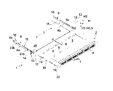
Figures 1 and 2 show a carrier arrangement 1 according to a first exemplary
embodiment of the invention with a carrier unit 2 and a rail arrangement 3 for
the carrier
unit 2, wherein the carrier unit 2 is illustrated in Figure 1 in a completely
pulled-out state
and in Figure 2 in a completely inserted state. In the exemplary embodiments,
the
carrier units are each designed as patch panels 2, but this should not be
understood as
restrictive. The rail arrangement 3 can be suitable in principle for use with
any desired
carrier units, in particular also for use with trays or dummy elements.
The patch panel 2 has a front interface or connection panel 4 and a rear
interface 5. A
plurality of cassettes 6 which can each have optical and/or optical-electrical
plug-in
connectors 7 are arranged in the region of the front connection panel 4. Patch
panels 2
are known in principle and are available in many different variants, and
therefore more
specific details will not be discussed here.
The rail arrangement 3 has a first mounting rail 8 and a separate second
mounting rail
9. The two mounting rails 8, 9 are spaced apart from one another (cf. distance
d in
Figure 1 along a first translation degree of freedom) and are designed to
receive the
patch panel 2 jointly between them.
In the exemplary embodiments, the rail arrangement 3 is designed to guide the
patch
panel 2 movably along and counter to an insertion direction E (or along a
second
translation degree of freedom orthogonally to the first translation degree of
freedom).
In the exemplary embodiments, the first mounting rail 8 and the second
mounting rail 9
each have the same structural design, but are formed and arranged mirror-
symmetrically with respect to one another.
Each of the mounting rails 8, 9 has at least one fastening point 10 for
fastening to a
distribution frame 11 (cf. Figures 13 and 14). In Figure 1, by way of example,
an
individual vertical strut 12 of the distribution frame 11 with respective
fastening positions
Date Recue/Date Received 2023-08-09
-28-
13 is indicated by dashed lines. The fastening points 10 are each arranged on
a bent-
over, lateral portion 14 (a lug) of the respective mounting rail 8, 9 and are
designed as
elongate bores in order to create a compensation option for tolerances. The
fastening
points 10 or elongate bores can be finally arranged in alignment with the
desired
fastening positions 13 of the distribution frame 11 or of the corresponding
vertical strut
12 of the distribution frame 11, and therefore the first mounting rail 8 and
the second
mounting rail 9 are preferably arranged at the same height position H in the
distribution
frame.
As a rule, the height positions H or fastening points 10 of the distribution
frame 11 are
arranged in a defined grid and are each spaced apart from one another by a
third of a
height unit U. The overall height h (with respect to a third translation
degree of freedom
orthogonal to the first two translation degrees of freedom) of the first
mounting rail 8 and
of the second mounting rail 9 or the entire carrier arrangement 1 is
preferably selected
in such a manner that it does not exceed one third of a height unit U, and
therefore as
compact a stack, or register, as possible of a plurality of carrier
arrangements 1 can be
arranged in the common distribution frame 11. Corresponding stacks of carrier
arrangements 1 that are also referred to within the scope of an embodiment of
the
invention as "rail assemblies" are illustrated by way of example in Figures 7
and 14. In
particular, a carrier housing for the patch panel 2 or the patch panels 2 can
be
dispensed with, as a result of which a greater patch panel density can be
achieved in
the distribution frame 11. According to the prior art, fastening or spacing
can be realized
as a rule only in integer multiples of a height unit U.
It should be mentioned at this juncture that also, depending on the
application, a
plurality of insertion directions E can be provided for a carrier unit or a
patch panel 2, in
particular a first insertion direction and a second insertion direction
opposed to the first
insertion direction (for example if, in the mounted state of the rail
arrangement 3 in the
distribution frame 11, an access option for the service engineer from opposite
sides,
i.e., for example, from the front and rear, is intended to be ensured in order
to enable
the service engineer to push out and insert the carrier unit or the patch
panel 2 from
both sides of the distribution frame 11). However, for simpler understanding,
an
embodiment of the invention will be described here essentially with precisely
one
insertion direction, as also illustrated in Figure 1, but this should not be
understood as
restrictive.
Date Recue/Date Received 2023-08-09
-29-
In all of the exemplary embodiments, the mounting rails 8, 9 are of multi-part
design,
but this in principle should not be understood as restrictive. In the
exemplary
embodiments, each of the mounting rails 8, 9 has a profile rail 8a, 9a
(preferably a
.. primarily L-shaped profile rail 8a, 9a) manufactured from sheet metal) and
a functional
component 8b, 9b fastened mechanically rigidly and directly to the profile
rail 8a, 9a.
The profile rail 8a, 9a forms a supporting surface 15 for the patch panel 2,
said
supporting surface running along the second translation degree of freedom y.
In the exemplary embodiment of Figures 1 and 2, the mounting rails 8, 9 each
have a
rear-side movement limiting means 16 in order to limit the movement of the
patch panel
2 along the insertion direction E. The exemplary embodiment illustrated in
Figures 1
and 2 involves elastic movement limiting means 16, as a result of which the
service
engineer is additionally assisted in pushing the patch panel 2 out of the rail
arrangement 3. Alternatively to an elastic movement limiting means 16,
however, a rigid
movement limiting means 16 can also be provided, as illustrated in Figure 3,
or a
magnetic movement limiting means 16 (cf. Figure 4). In the exemplary
embodiments,
the movement limiting means 16 is in each case formed on the functional
component
8b, 9b.
It is also intended to be clarified with reference to Figure 11 that a
movement limiting
means 16 which cannot be overcome is not necessarily required in the context
of an
embodiment of the invention. In principle, a movement limiting means 16 which
can be
overcome can also be provided to provide the option of pulling the patch panel
2 on the
rear side out of the rail arrangement 3 if a certain force component is
overcome or a
corresponding latching lever 17 is unlocked. The accessibility and
mountability for the
service engineer can thus be further simplified.
In order to further improve the guiding of the patch panel 2 along the rail
arrangement 3,
.. a linear guide pair can be formed between at least one of the two mounting
rails 8, 9
and a side surface 18 of the patch panel 2, with a first connecting partner 19
of the
linear guide pair being designed as a guide groove and a second connecting
partner 20
of the linear guide pair as a corresponding sliding block. In the exemplary
embodiments, the sliding block or the second connecting partner 20 is in each
case
formed on the functional component 8b, 9b.
Date Recue/Date Received 2023-08-09
-30-
Also, in addition to the movement limiting means 16 already described, a
fixing
arrangement 21 can be formed between at least one of the two mounting rails 8,
9 and
a side surface 18 of the patch panel 2 in order to fix the patch panel 2 in at
least one
pulled-out position along or counter to the insertion direction E. For
example, fixing in a
partially pulled-out position (cf. Figure 9) or in a completely pulled-out
position (cf.
Figure 10) can be possible. Fixing in the operating position (in the present
case a
completely closed position, cf. Figure 2, for example) can also be provided. A
corresponding fixing arrangement 21 can preferably be designed using a spring-
elastic
latching lever 17 and a latching recess or an offset 22 for the latching lever
17 in order
to provide releasable fixing of the pulled-out position of the patch panel 2
between the
two mounting rails 8, 9. A magnetic fixing arrangement 21 (cf. Figure 4) can
also be
possible in principle. In the exemplary embodiments, the latching lever 17 is
in each
case formed on the functional component 8b, 9b.
In the exemplary embodiments, the sliding blocks or second connecting partners
20 are
each formed in one part with the latching lever 17 of the fixing arrangement
21 of the
mounting rail 8, 9 in order to unlock the linear guide.
It should be mentioned at this juncture that the linear guide pair, i.e., for
example, the
combination of guide groove or first connecting partner 19 and sliding block
or second
connecting partner 20, can optionally also extend over the entire length of
the side
surface 18 of the patch panel 2 and/or the entire length of the mounting rail
8,9, even if
this is not illustrated in the exemplary embodiment.
An embodiment of the invention is also suitable particularly advantageously
for use with
patch panels 2 which are pivotable or which can be folded over, as illustrated
in
Figure 12. Folding over can therefore take place either in the partially
pulled-out
position or completely pulled-out position of the patch panel 2 in order to
further
improve the accessibility.
The multi-part mounting rails 8, 9 can preferably have a latching connection
between
the profile rail 8a, 9a and the corresponding functional component 8b, 9b. For
this
purpose, the profile rail 8a, 9a has a plurality of connecting elements
(latching recesses
23a in the exemplary embodiment) and the functional component 8b, 9b has a
plurality
Date Recue/Date Received 2023-08-09
-31-
of appropriately corresponding connecting elements (latching elements 23b in
the
exemplary embodiment) in order to produce a mechanically stable and if
required
dismountable connection between the profile rail 8a, 9a and the functional
component
9a, 9b.
An option for mechanically stiffening the carrier arrangement 1 will be
presented below
with reference to Figures 5 to 10. In particular if a plurality of patch
panels 2 are
intended to be mounted stacked one above another, it can be advantageous to
mechanically reinforce the respective mounting rails 8, 9. For this purpose,
firstly,
folded-over edges 24 can be provided along the longitudinal axis (cf. in
particular
Figures 5 and 6). Alternatively or additionally, provision can be made that
the mounting
rails 8, 9 each have at least one connecting device 25 (cf., for example,
Figure 6). In the
exemplary embodiments, in each case three connecting devices 25 are provided
by
way of example. The connecting devices 25 are each designed to mechanically
connect
the respective mounting rail 8, 9 to a directly adjacent further mounting rail
8, 9
arranged above and/or below it.
The mounting rail 8, 9 has, per connecting device 25, in each case a top-side
connecting recess 26 and a bottom-side connecting recess 27 which are each
arranged
in alignment with one another (cf. sectional illustration in Figure 8). In the
exemplary
embodiments, the top-side connecting recess 26 is formed in the functional
components 8b, 9b and the bottom-side connecting recess 27 in the profile rail
8a, 9b.
The connecting recesses 26, 27 are each realized as combination of passage
bore and
elongate hole. In order to connect the mounting rails 8,9, a connecting means
28 is in
each case provided which is designed as a separate connecting member and which
can be mounted with at least one first end portion 29 in one of the connecting
recesses
26, 27 and additionally can be latched to the respective other connecting
recess 27, 26
of an adjacent rail arrangement 3. The latching first end portion 29 is thus
able to
expand after penetrating the opposite connecting partner, as a result of which
a form fit
can be provided. If therefore a plurality of mounting rails 8, 9 are connected
together to
form a stack/to form a rail assembly or to form a register, the connecting
member or the
connecting means 28 engages from one functional component 8b, 9b in the basic
profile of the mounting rail 8, 9 located thereabove and expands. The
connection
creates an increased mechanical stability of the overall assembly and prevents
the
patch panel 2 from sagging or being distorted when it is fully populated. The
connecting
Date Recue/Date Received 2023-08-09
-32-
member or connecting means 28 can preferably be formed on a second end portion
30
and can receive the first end portion 29 of a connecting member or connecting
means
28 of an adjacent rail arrangement 3 therein (cf. Figure 8).
.. The proposed connecting device 25 is suitable particularly advantageously
for a
narrowly spaced-apart arrangement of patch panels 2. In order to ensure that
even the
topmost unit of the entire register makes up no more than 1/3 of a height unit
U, the
connecting members or connecting means 28 can be removable since a connecting
member or connecting means 28 leading further is generally not required for
the
topmost unit of the stack ¨ in this way, the construction space can be further
optimized.
Optionally, however, spacers can also be provided (not illustrated in the
figures). Said
spacers make it possible to counter the offset of the screw connection
positions, which
offset occurs in many types of distribution frames 11, at spacings of one
height unit U.
The spacers can be designed as an additional component or formed in one part
with
the connecting members 28.
Alternative variants of a connecting device 25 are also possible within the
context of an
embodiment of the invention, for example a connecting means 28 of plate-like
or rail-
shaped design (indicated by way of example by dashed lines in Figure 7) which
is
fastenable to the side surfaces of the mounting rails 8, 9 to be connected.
For this
purpose, the plate-like or rail-shaped connecting means 28 and the mounting
rails 8, 9
can have, for example, respective bores in order to permit a suitable screw
connection,
latching connection or plug-in connection.
Figure 13 illustrates a distribution frame 11 in which a plurality of rail
arrangements 3
are arranged in order to realize respective slots or trays for patch panels 2
at a small
spacing at different height positions H. However, a vertical or oblique
arrangement is
also possible, as already mentioned. The individual mounting rails 8, 9 of the
respective
rail arrangements 3 are in each case correspondingly connected to the vertical
struts 12
of the distribution frames 11.
Finally, Figure 14 shows a fiber-optic distribution system 31 with the
distribution frame
11 and a plurality of carrier arrangements 1. According to an embodiment of
the
invention, the connection density can be extremely great, with simultaneously
good
Date Recue/Date Received 2023-08-09
-33-
accessibility. The construction space in the distribution frame 11 can be
utilized virtually
optimally.
Date Recue/Date Received 2023-08-09