Note: Descriptions are shown in the official language in which they were submitted.
WO 2022/178585
PCT/AU2022/050147
1
Percussion Drilling Apparatus and Torque Transfer Method
Field of the Invention
[0001] The present invention relates to an apparatus and methods used during
percussion
drilling operations.
Background
[0002] The following discussion of the background art is intended to
facilitate an understanding
of the present invention only. It should be appreciated that the discussion is
not an
acknowledgement or admission that any of the material referred to was part of
the common
general knowledge as at the priority date of the application.
[0003] Percussion drilling, such as reverse circulation drilling, uses a bit
which is repeatedly
hammered to fracture rock and progressively drill or bore through the earth.
Percussion drilling
creates a harsh environment which is not conducive to measuring tools and
components which
are sensitive to rapid changes in motion and/or repeated impacts with the
associated
shock/vibration.
[0004] Traditional methods of percussion drilling operations are conducted in
at least two stages
which include a drilling stage and a logging stage. During the drilling stage
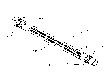
a drill string is
mechanically operated by drilling machinery. Following which, the second stage
requires
separately lowering additional equipment to log information about the hole
that has been drilled
including depth, density and gamma radiation of the drilling formation.
[0005] Devices that can reduce and/or eliminate the need or timing of the
second stage are
commonly sought. It is against this background that the present invention is
presented.
[0006] Throughout the specification unless the context requires otherwise, the
word "comprise"
or variations such as "comprises" or "comprising", will be understood to imply
the inclusion of a
stated integer or group of integers but not the exclusion of any other integer
or group of integers.
[0007] Throughout the specification unless the context requires otherwise, the
word "include" or
variations such as "includes" or "including", will be understood to imply the
inclusion of a stated
integer or group of integers but not the exclusion of any other integer or
group of integers.
CA 03209348 2023- 8- 22
WO 2022/178585
PCT/AU2022/050147
2
Summary of Invention
[0008] According to a first aspect there is provided a drill rod for
transferring torque comprising
a casing for connection in a drill string; the casing coupled to an internal
body by a torque
transferring mechanism at each end of the casing such that torque applied to
an end of the drill
rod is transferred through both of the casing and the body.
[0009] In an embodiment, the torque transferring mechanism comprises splines
and
complementary mating portions.
[0010] In an embodiment, the splines are configured to engage with the
complementary mating
portions, forming a splined connection to transfer torque.
[0011] In an embodiment, the torque applied to the casing is also applied to
the internal body.
[0012] In an embodiment, the torque applied to the internal body is also
applied to the casing.
[0013] In an embodiment, the casing is separable from the internal body.
[0014] In an embodiment, the internal body has one or more fluid supply
channels and a fluid
return channel.
[0015] In an embodiment, the casing comprises complementary mating portions at
both ends
and the internal body comprises splines at both ends.
[0016] In an embodiment, the complementary mating portions of the casing are
configured to
slidably receive the splines of the internal body.
[0017] In an embodiment, an outer diameter of the splines at a first end of
the internal body is
smaller than an inner diameter of the complementary mating portion at a second
end of the
casing, so that the internal body is required to be slidably inserted into the
casing from the second
end.
[0018] In an embodiment, the torque transferring mechanism extends
continuously around an
entire annular portion between the internal body and the casing.
[0019] In an embodiment, the torque transfer mechanism comprises a continuous
complementary mating profile protruding inwardly from the casing and a
continuous splined profile
protruding outwardly from the internal body.
CA 03209348 2023- 8- 22
WO 2022/178585
PCT/AU2022/050147
3
[0020] In an embodiment, the or each torque transferring mechanism can be
coupled to another
drill rod having one or more annuluses.
[0021] In an embodiment, the drill string comprises a percussion drill bit and
a measuring
instru ment.
[0022] In an embodiment, an upper end of the internal body comprises
connection means for
fluidly connecting to a multi annulus drill rod above the torque transferring
mechanism located at
the upper end of the internal body as well as to another multi annulus drill
rod below the lower
torque transferring mechanism located at a lower end of the internal body.
[0023] According to a second aspect there is provided a second aspect there is
provided a drill
apparatus comprising the drill rod of the first aspect.
[0024] According to a third aspect there is provided a method of transferring
torque from one
end of a drill rod to another comprising transferring torque via both a casing
and an internal body.
[0025] In an embodiment, the method further comprising transferring torque
from a first end of
the drill rod to the casing and the internal body.
[0026] In an embodiment, the method further comprising transferring torque
from the casing
and the internal body to a second end of the drill rod.
Brief Description of Drawings
[0027] Preferred embodiments of the invention will now be described with
reference to the
following drawings, in which:
Figure 1 is a side view of a drill rod comprising a damping apparatus
according to an embodiment
of the present invention;
Figure 2 is a side view of the drill rod without the casing showing the
damping apparatus according
to an embodiment of the present invention;
Figure 2A is an isometric view of the casing which may cover the damping
apparatus according
to an embodiment of the present invention;
CA 03209348 2023- 8- 22
WO 2022/178585
PCT/AU2022/050147
4
Figure 2B is an isometric view of the measuring instruments coupled to the
damping apparatus
within the body according to an embodiment of the present invention;
Figure 3 is a cross-sectional view of the drill rod having inner compartments
with a damper
apparatus according to an embodiment of the present invention;
Figure 4 is an isometric view of a body of the drill rod having compartments
arranged longitudinally
around the perimeter of the body according to an embodiment of the present
invention;
Figure 5 is an isometric view of a lower portion of the body showing a down
hole spline according
to an embodiment of the present invention;
Figure 6 is a cross-sectional view of the lower end of the casing which
engages with the spline
shown in Figure 5 according to an embodiment of the present invention;
Figure 7 is an isometric view of an upper end of the casing which engages with
an upper uphole
spline shown in Figure 8 according to an embodiment of the present invention;
and
Figure 8 is an isometric view of the upper portion of the body showing the
uphole spline according
to an embodiment of the present invention.
Description of Embodiments
[0028] Referring to Figures 1, 2, 2A, and 2B there is provided drill rod 5
comprising an elongate
body 10 within a cylindrical casing 12 having ends suitable for connection
into a percussion drilling
drill string in place of a standard drill rod. Typically, this will be
immediately behind the bottom
hole assembly including the drill head in the drill string since the
measurements are desired to be
taken from a position immediately behind the drill head.
[0029] The body 10 comprises longitudinally extending compartments 212
arranged around an
outer diameter of the body 10. Each compartment 212 is in the form of a recess
or slot as seen
in Figures 2B and 4. In an embodiment there are two large compartments 212 on
opposite sides
of the body 10. The large compartments 212 are able to receive one or more
measuring
instruments 180, as described further below. In an embodiment there may be
additional
compartments, such as smaller compartments 212' on opposite side of the body
10, and each
between two of the larger compartments 212.
[0030] Percussion drilling is an umbrella term that includes but is not
limited to, reverse
circulation drilling and air core drilling. The present invention may be
suitable for any form of
CA 03209348 2023- 8- 22
WO 2022/178585
PCT/AU2022/050147
drilling where the drill string experiences high impact and/or repetitive
impact forces. The forces
that the measuring instrument 180 experiences may be axial, radial and/or
rotational
shock/vibration experienced independently, or a combination of the
aforementioned. Such forces
may impede the measuring instrument 180 from collecting accurate data and/or
functioning
entirely.
[0031] Referring to Figures 5 to 8, there is provided an upper end of body 10
having a torque
transferring mechanism. In an embodiment the torque transferring mechanism
comprises a
plurality of splines 414 and complementary spline mating portion 416
comprising complementary
grooves for receiving the splines 414. The lower end of the body 10 comprising
a torque
transferring mechanism, preferably comprising a plurality of splines 418 and
complementary
spline mating portion 420 comprising complementary grooves. An alternative to
the splines
includes a sawtooth shaped set of teeth. Each torque transferring mechanism
provides a physical
connection which, when a torque is applied to a portion of the drill rod 5,
the torque is transferred
through each of the body 10 and the casing 12. The transfer of torque between
the body 10 and
casing 12 provides additional rigidity and strength during percussion drilling
operations and/or
operations which impart high and/or repetitive torque loads.
[0032] Again, referring to Figures 6 and 7, there is provided a profile within
the upper end of
casing 12 and the lower end of casing 12 in the form of respective
complementary spline mating
portions 416, 420, respectively. The complementary spline mating portion 416
receives each of
the teeth or splines 414 positioned on the body 10 at the upper portion of the
body 10. The spline
mating portion 420 receives each of the teeth or splines 418 located on the
lower portion of the
body 10. The splines 414, 418 mesh with the profile of complementary spline
mating portion 416,
420, respectively.
[0033] In alternative embodiments, the splines 414, 418 may be positioned on
the casing 12
and the respective complementary spline mating portions 416, 420 may be
located on the body
10. The splines 414, 418 may be affixed to the body 1001 integrally formed
therein. Alternative
embodiments may have the splines 414, 418 affixed to the casing 12 or
integrally formed therein.
Complementary spline mating portions 416, 420 may be affixed to the casing 12
or integrally
formed therein. Alternative embodiments may have the complementary spline
mating portions
416, 420 affixed to the body 10 or integrally formed therein.
[0034] The combination of spline 414 and complementary spline mating portion
416 form a
torque transferring mechanism which is also able to be separated so as to
provide access to the
to the interior of the casing, such as to compartments with measuring
instrument(s) therein. The
CA 03209348 2023- 8- 22
WO 2022/178585
PCT/AU2022/050147
6
interaction of spline 418 and complementary mating portion 420 provide a
physical connection for
sharing a torque load between the body 10 and casing 12. Each torque
transferring mechanism
transfers a torque applied to the body 10 throughout the body 10 and the
casing 12. Conversely,
the torque applied to the casing 12 is applied to the casing 12 and the body
10.
[0035] The casing 12 comprises complementary spline mating portions 416, 420
which slideably
receives the body 10, the body 10 comprising spline 414, 418. To slideably
receive the body 10
within the casing 12, the outer diameter at spline 418 must be smaller than an
inner diameter of
the complementary spline mating portion 416. In an embodiment, the casing is
separable from
the internal body. In an alternative embodiment, the body 10 and casing 12 may
each comprise
one of the splines 414, 418 and one of the complementary spline mating
portions 416, 420.
Alternatively, the outer diameter of spline 414 may be smaller than an inner
diameter of the
complementary spline mating portion 420 requiring the body 10 to be slideably
inserted into the
casing 12 from the opposite end.
[0036] As discussed above, the upper portion of the body 10 comprises
connection means for
fluidly connecting to a multi annulus drill rod above the torque transferring
mechanism located at
the upper end of the body 10 as well as below the lower torque transferring
mechanism located
at the lower end of the body 10. The annulus of the drill rod above the body
10 in the drill string
fluidly connects with the upper end of the body 10 at or adjacent to the upper
torque transferring
mechanism. The lower end of the body 10 connects with the annulus of the drill
rod or bottom
hole assembly below the body 10 at or adjacent to the lower torque
transferring mechanism.
[0037] In use measuring the orientation of a measurement tool during
percussion drilling
operations comprises drilling a hole using a drill string having a percussion
drill bit and, preferably,
a measuring instrument 180; transferring torque applied to the drill string to
an end of the drill rod
through the casing 12 and the body 10 to an opposite end of the drill rod 5,
and preferably,
measuring the orientation of the tool as the hole is being drilled. As the
drill string progressed into
the drilled bore hole the action of the percussion drill bit is paused to add
another drill rod, and
when the drill string is extracted drill rods are removed. During each pause
in drilling the
measuring instrument 180 takes a calibration measurement. Because torque
transfer is shared
by the casing 12 and the body 10, the casing 12 can potentially be thinner
than in a standard drill
rod, which allow for greater clearance between the measuring instrument 180
and the casing 12,
or for more space to accommodate the measuring instrument 180.
[0038] In the context described herein, pneumatic percussion drilling is where
there is a hammer
actuated by pressurised air that strikes an anvil component of or connected to
a drill bit so that
the drill bit impacts on rock on the bottom of a drill hole so as to break the
rock. The hammer is
CA 03209348 2023- 8- 22
WO 2022/178585
PCT/AU2022/050147
7
directly next to the drill bit. This type of percussion drilling is used in
rotary air blasting (RAB) and
reverse circulation drilling (RC drilling). Pneumatic percussion drilling is
used in mineral
exploration. It is to be distinguished from hydraulic (often water or mud)
powered percussion
drilling used in hydrocarbon well drilling. It is also to be distinguished
from mechanical percussion
drilling where the drill string is lifted and dropped, usually from the
surface. In hydraulic and
mechanical percussion drilling a casing within which the drill string can move
is usually used.
However, in pneumatic percussion drilling a casing is usually not used.
[0039] RC drilling will be understood to be where the pressurised air flow is
also used to blow
the rock broken by the drill bit impact into one or more holes in the drill
bit and then up through
the drill string. The drill rods have an inner tube through which the air and
recovered rock return
to the surface and an outer tube, which between this and the inner tube, the
pressurised air travels
down the drill string to the hammer and the drill bit. This is distinguished
from RAB, which is where
the broken rock air is blown up the drill hole outside of the drill string.
The inner tube is not required
in the drill rods for RAB.
[0040] Percussion drilling can be distinguished from air core drilling where
the drill bit cuts,
rather than breaks from impact, but there is pressurised air that returns the
cuttings through the
drill string. Percussion drilling can also be distinguished from diamond core
drilling where ring is
cut by diamond teeth and a core sample can be retrieved.
[0041] Modifications may be made to the present invention within the context
of that described
and shown in the drawings. Such modifications are intended to form part of the
invention
described in this specification.
CA 03209348 2023- 8- 22