Note: Descriptions are shown in the official language in which they were submitted.
PCT/BR 2022/050 054 - 23-12-2022
1
Specification of a Patent of Invention for a "SYSTEM AND
METHOD FOR MEASURING GRAIN PARTICLE GRANULOMETRY
AND GRAIN PARTICLE GRANULOMETRY MEASUREMENT
SYSTEM CALIBRATION METHOD".
[0001] This invention refers to a measurement system, a
measurement method, and a calibration method for a grain particle
granulometry measurement system run through a cracking process, in
order to define their particle granulometry and analyze its functioning.
Background Art
[0002] The methods for measuring the grain particle
granulometry,
for example, cracked soybeans, that are widely known and used at the
prior art involve a non-automated measurement of the grains. This non-
automated measurement method requires the practical training and
development of qualified workers skilled in obtaining information from
the measured matter, in this case, cracked grains. This need leads to
dependence on a skilled worker who is trained and qualified to handle
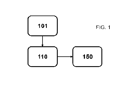
this job. Furthermore, human errors associated with measurements,
process slowdowns, and possible non-measurements increase the
inefficiency of non-automated methods, causing losses to the industry.
[0003] In order to lessen possible human errors and enhance
process efficiency, several segments of the agricultural industry
developed devices as substitutes that can handle some tasks performed
inefficiently by people.
[0004] An example of a device at the prior art developed to
solve the
problem of monitoring the quality of agricultural produce and fruits during
processing, storage, and/or transportation is described in document BR
102013021712-3. This device is intended to detect and quantify the
impacts imposed on fruits and vegetables during post-harvest
processing, in order to reduce the amount of bruising and crushing, thus
extending the useful life of this produce. The devices at the prior art that
CA 03209370 2023- 8- 22
AMENDED SHEET
PCT/BR 2022/050 054 - 23-12-2022
2
were created for these purposes and have some characteristics that are
similar to the produce to be monitored, in this case, fruits and vegetables,
are called pseudofruits in the mentioned document.
[0005] However, these devices at the prior art are
configured to
simulate the characteristics of the monitored produce, such as, for
example, being spherical in shape to define the presence of physical
damage to foods stored or transported with the device. Consequently,
the devices known at the prior art are not suitable for measuring particle
granulometry in flows of cracked grains with efficiency and precision, nor
for analyzing their functioning.
[0006] Another example of system of the prior art is
disclosed in
document US5309374. Such document teaches a quality determination
system enclosed within a housing that includes a drop tube feeder
apparatus, a video imaging device, and a quality control rejection device.
However, in contrast with the present invention, the disclosed system
measures the impact of one soybean at a time and the signal generated
by this individual impact is used for grain quality analysis based on mass
and hardness characteristics, resulting in a less agile and efficient
measurement.
[0007] The document EP 3395154 discloses a harvesting
machine
capable of sensing an amount of crop material being harvested. Such
document focuses on determining the approximate percentage of
"material other than grain" present in the collected material and is not
capable of measuring a grain particle granulometry.
[0008] Document W02021/003346 systems and methods for
detecting aeration properties in fluids using a vibration sensor. Despite
being capable of evaluating a signal received from the vibration sensor,
such system is not capable of measuring a grain particle granulometry
nor suggests the evaluation of parameters obtained from the impact of
grains on a surface.
CA 03209370 2023- 8- 22
AMENDED SHEET
PCT/BR 2022/050 054 - 23-12-2022
3
Purposes of the Invention
[0009] In view of the problems described at the prior art,
the purpose
of this invention is to provide a grain particle granulometry measurement
system, a grain particle granulometry measurement method, and a
calibration method for a grain particle granulometry measurement
system that can measure grain particle granulometry, based on the
vibration characteristics of a vibration generated by the impact of the
grain flow on a surface.
[0010] The measurements performed by the system and methods
addressed by this invention of the vibration characteristics generated by
the impact of the grain flow onto a surface result in more precise and
efficient measurements of grain particle granulometry, such as, for
example, cracked soybeans, compared to solutions available at the prior
art. Furthermore, the system and methods addressed by this invention
allow this measurement to be performed in an automated and
continuous manner.
Brief Description of the Invention
[0011] This invention describes a grain particle
granulometry
measurement system that comprises a vibration measurement device
and a processing unit. The processing unit is connected to the vibration
measurement device. The vibration measurement device is configured
to measure the vibration characteristics of a vibration caused by impacts
generated by the grain flow in the vibration measurement device and
send the measured vibration characteristics to the processing unit.
[0012] The processing unit may be configured to estimate
the
particle granulometry of the grain flow, based on the vibration
characteristics. The grain flow particle granulometry may be estimated,
based on a mathematical model predefined in the processing unit. The
mathematical model may be defined based on the measured vibration
characteristics, based on the grain flow from samples classified by
CA 03209370 2023- 8- 22
AMENDED SHEET
PCT/BR 2022/050 054 - 23-12-2022
4
particle granulometry.
[0013] The vibration measurement device comprises a
vibration
sensor. The vibration sensor may be an accelerometer. The vibration
sensor may be a capacitive accelerometer.
[0014] The vibration measurement device comprises an impact
plate, wherein the impacts generated by the grain flow in the vibration
measurement device are generated on the impact plate. The impact
plate may be a contact surface configured to withstand impacts resulting
from the grain flow and allow the vibration sensor to collect information
on the impacts generated by the grain flow. The surface of the impact
plate may be inclined in relation to the direction of the grain flow.
[0015] The vibration measurement device may also comprise a
regulator and a passageway, wherein the regulator is connected to the
passageway and the passageway is connected to the impact plate,
wherein the regulator limits the grain flow, wherein the impact plate is
inclined in relation to the longitudinal axis of the passageway.
[0016] This invention describes a grain particle
granulometry
measurement method that comprises the steps of: measuring the
vibration characteristics caused by the impact of the grain flow through
a vibration measurement device; and calculating a grain particle
granulometry in the grain flow, based on the measured vibration
characteristics. The step of calculating the grain particle granulometry
comprises inserting the vibration characteristics into a predefined
mathematical model.
[0017] The grain particle granulometry measurement method
may
also comprise a step of creating a mathematical model, based on the
vibration characteristics of the grain flow from samples screened
individually.
[0018] This invention also describes a calibration method
for a grain
particle granulometry measurement system that comprises the steps of:
CA 03209370 2023- 8- 22
AMENDED SHEET
PCT/BR 2022/050 054 - 23-12-2022
classifying grain samples by particle granulometry; measuring the
vibration characteristics of a vibration caused by the impact of the grain
flow of each one of the grain samples through a vibration measurement
device; and creating a mathematical model, based on the measured
vibration characteristics for each one of the grain samples. The
mathematical model may be a set of equations prepared in a manner
that allows the calculation of a grain particle granulometry for the grain
flow whose particle granulometry is unknown. The step of classifying
grain samples individually may be performed through screening.
Brief Description of the Drawings
[0019] This invention will be described in greater detail
below, based
on an example of its embodiment, shown in the drawings. The Figures
display:
Figure 1 ¨ is a schematic diagram of an embodiment from the grain
particle granulometry measurement system addressed by this invention;
Figure 2 ¨ is the side view of the vibration measurement device of an
embodiment from the grain particle granulometry measurement system
addressed by this invention;
Figure 3 ¨ is a sequence of steps for an embodiment of the calibration
method for a grain particle granulometry measurement system
addressed by this invention; and
Figure 4¨ is a sequence of steps for an embodiment of the grain particle
granulometry measurement method addressed by this invention.
Detailed Description of the Drawings
[0020] Figure 1 shows a schematic diagram from the grain
particle
granulometry measurement system 100 according to an embodiment of
this invention. In this example of an embodiment, the grain particle
granulometry measurement system 100 comprises a vibration
measurement device 110 and the processing unit 150.
[0021] The vibration measurement device 110 and the
processing
CA 03209370 2023- 8- 22
AMENDED SHEET
PCT/BR 2022/050 054 - 23-12-2022
6
unit 150 are interconnected, whereby the vibration measurement device
110 is configured to send information to the processing unit 150. This
information is sent through a signal transmission which may be handled
by remote or physical connections, not being limited to any specific
signal transmission type.
[0022] The grain particle granulometry measurement system
100
addressed by this invention is positioned close to a grain flow 101 source
where the grain flow originates. An example of a grain flow 101 source,
according to one embodiment, is a cracking mill. The cracking mill may
be, for example, a soybean cracking mill. In this case, the grain particle
granulometry measurement system 100 can assess whether the
soybeans processed in the cracking mill are compliant with the desired
specifications. Although a mill is used as an example of a grain flow 101
source in this embodiment, the grain flow may come from other sources,
such as, for example, a storage bin or a plurality of screens or sieves.
This last example may be used, for example, during system calibration.
[0023] An embodiment of the vibration measurement device
110 is
shown in Figure 2. In this embodiment, the vibration measurement
device 110 comprises a hollow body with a square, rectangular, or
circular cross-section. The body of the vibration measurement device
110 comprises a collection element 112, a grain tank 114, a regulator
116, a first return path 118, a vibration sensor 119, a second return path
122, and an impact plate 120. These elements comprising the body of
the vibration measurement device 110 are interconnected, whereby the
grain flow from the grain flow 101 source Jen flow through the vibration
measurement device 110, whereby the grain particle granulometry
measurement can be performed.
[0024] The collection element 112 handles the collection of
the grain
flow. In this embodiment, the collection element 112 comprises a grain
flow receiving end where the grains forming the grain flow are received.
CA 03209370 2023- 8- 22
AMENDED SHEET
PCT/BR 2022/050 054 - 23-12-2022
7
The receiving end is an open section of the hollow body that allows the
grain flow to enter the device. The opening in the open section may be
accentuated by a longitudinal cut along a section of the collection
element 112, for easier receipt of the grains.
[0025] The collection element 112 is connected to the grain
tank 114
to which the grain flow is directed after its receipt in the vibration
measurement device 110. In addition to being connected to the
collection element 112, the grain tank 114 is also connected to the first
return path 118 and the regulator 116. The grain tank 114 is configured
to hold grains coming from the collection element 112 and that will
subsequently run through the regulator 116 or the first return path 118.
As it accumulates grains in its interior, the grain tank 114 may reach the
grain holding limit, which is defined by its construction characteristics.
When this grain holding limit is reached, the grains accumulated in the
grain tank 114 are directed to the first return path 118.
[0026] The first return path 118 is configured to limit the
quantity of
grains held in the grain tank 114. When the accumulation of grains
reaches the position where the first return path 118 is connected to the
grain tank 114, the grains are directed to the first return path 118. Having
run through the first return path 118, the grains are directed to other
finalities, such as, for example, returning to the grain flow that will be
measured by the vibration measurement device 110 or going to another
destination.
[0027] The regulator 116 is the component of the vibration
measurement device 110 that regulates the grain flow that will be
measured. In other words, if the grain flow is higher than the level
suitable for performing the measurement, it is restricted or limited by the
regulator 116. In this embodiment, the regulator 1 1 6 represents a narrow
region of the body of the vibration measurement device 110, in other
words, a reduction in the cross-section at a defined point. This narrowing
CA 03209370 2023- 8- 22
AMENDED SHEET
PCT/BR 2022/050 054- 23-12-2022
8
controls the passage of the grain flow. Although a specific form of grain
flow regulation is described, other means of limitation may also be used.
[0028] The regulator 116 is connected to the grain tank 114
and a
passageway 117 that directs the grain flow towards the impact plate 120,
where the vibration sensor 119 performs the measurement. The impact
plate 120 is a contact surface of the vibration measurement device 110
configured to withstand an impact of the grain flow. The surface of the
impact plate 120 is a surface configured to withstand the impacts of the
grain flow and to generate vibration, based on this impact. This vibration
can be measured by the vibration sensor 119 located close to or on the
impact plate and allows the vibration sensor 119 to collect information
on the impacts generated by the grain flow on the impact plate 120.
[0029] To generate the vibration to be measured by the
vibration
sensor 119, the impact plate 120 is inclined in relation to the longitudinal
axis of the passageway 117, in other words, inclined, in relation to the
direction of the grain flow. This inclination allows the grain flow to come
into contact with the impact plate 120, resulting in an impact that
generates the vibration.
[0030] In one embodiment, the vibration sensor 119 of the
vibration
measurement device 110 is an accelerometer that can measure the
actual exhilaration of the vibration measurement device 110 in relation
to the grain flow. In this embodiment, the accelerometer is a capacitive
accelerometer. However, other types of accelerometers may also be
used, such as, for example, a piezoelectric accelerometer and a
piezoresistive accelerometer. Furthermore, the vibration sensor 119
may be another type of sensor able to measure a force of impact,
vibration and/or acceleration.
[0031] The vibration sensor 119 is the element of the
vibration
measurement device 110 that translates the vibration or the impact
received through the impact plate 120 when hit by the grain flow into an
CA 03209370 2023- 8- 22
AMENDED SHEET
PCT/BR 2022/050 054- 23-12-2022
9
electrical signal that may be sent to the processing unit 150 for
processing the information. By connecting the vibration sensor 119 with
the impact plate 120, the vibration measurement device 110 can
measure the vibration characteristics of the vibration caused by the
impacts of the grain flow on the impact plate 120 and send the measured
vibration characteristics to the processing unit 150.
[0032] The vibration characteristics are information on the
frequency
with which the vibration sensor 119 can capture the vibration generated
by the impact of the grain flow on the impact plate 120. These vibration
characteristics are sent to the processing unit 150 so that the processing
unit 150 can estimate the grain flow particle granulometry whose
vibration characteristics were measured.
[0033] In an alternative embodiment, the grain flow may be
dosed
so that the impact of each grain in the grain flow is spaced out, thus
generating a dynamic response with no overlapping. In this manner, it
would thus be possible to conduct an analysis of the signals in the time
domain, in order to estimate particle granulometry.
[0034] In one embodiment, a grain flow particle
granulometry is
estimated, based on a mathematical model predefined in the processing
unit 150. The mathematical model is a set of equations drawn up in a
manner that allows the control unit to calculate the grain particle
granulometry of the grain flow whose particle granulometry is unknown.
[0035] This mathematical model may be inserted into the
processing
unit 150, based on information from external databases, or developed,
based on a calibration conducted within the grain particle granulometry
measurement system 100. The calibration mathematical model is
defined based on the measured vibration characteristics, based on the
grain flow from samples classified by particle granulometry.
[0036] Figure 3 shows the calibration method from the grain
particle
granulometry measurement system according to an embodiment of this
CA 03209370 2023- 8- 22
AMENDED SHEET
PCT/BR 2022/050 054 - 23-12-2022
invention. The calibration method from the grain particle granulometry
measurement system is one of the ways of defining the mathematical
model to be used in the grain flow particle granulometry measurements.
Furthermore, in one embodiment, the calibration method from the grain
particle granulometry measurement system is designed to operate under
the conditions at the location where the grain particle granulometry
measurement system will be installed.
[0037] The calibration method is performed through
collecting
vibration data on individually-screened or sieved grain samples. The
individual vibration data are stored and processed in the processing unit,
through a computer program, and algorithms are drawn up to develop
the mathematical model, whose purpose is to perform the grain particle
granulometry measurements with precision and accuracy.
[0038] Initially, a step of separating 210 grain samples is
performed,
based on their particle granulometry characteristics. The grain samples
are sets of grains separated into groups with similar characteristics. Next
comes a step of classifying 220 the grain samples according to their
particle granulometries. The step of classifying the grain samples
individually may be performed through screening, for example, or any
other means of classifying grain samples.
[0039] This separation 210 and classification 220 of the
grain
samples allows the processing unit to create the mathematical model
that will be used in the grain particle granulometry measurement method.
[0040] After classifying 220 the grain samples according to
their
particle granulometries, a step of generating 230 the grain flow for each
one of the grain samples separately is performed. Next comes a step of
measuring 240 the vibration characteristics of the vibration caused by
the impact of the grain flow of each one of the grain samples in the
vibration measurement device. In other words, each grain flow
generated for each one of the grain samples is brought into contact with
CA 03209370 2023- 8- 22
AMENDED SHEET
PCT/BR 2022/050 054 - 23-12-2022
-11
the vibration measurement device. These contacts, or impacts, generate
vibrations with different vibration characteristics for each one of the grain
samples. Cross-referencing information on the different vibration
characteristics with the known grain sample particle granulometries
leads to the creation of the mathematical model.
[0041] In order to ensure that it is possible to cross-
references
information, the vibration sensor of the vibration measurement device
performs the step of translating 250 the generated vibrations into
electrical signals, sending these signals to the processing unit. On
receipt of the signal from the vibration measurement device, the
processing unit starts a step of performing 260 a signal processing
operation of the received signals. Next comes a step of performing 270
a data processing operation in order to organize and extract relevant
information from the measured vibration characteristics,
[0042] Based on the measured vibration characteristics for
each one
of the grain samples by the vibration measurement device, and by using
the algorithms developed to create the mathematical models, a step of
creating 280 the mathematical model is performed. The mathematical
model is a set of equations created in a manner that allows the
processing unit to calculate the grain particle granulometry of the grain
flow whose particle granulometry is unknown. Thus, with the
mathematical model created, the grain particle granulometry
measurement system is calibrated, whereby grain flows whose particle
granulometry is unknown can be measured.
[0043] Figure 4 shows the grain particle granulometry
measurement
method according to an embodiment of this invention. In this
embodiment, the grain particle granulometry measurement method is
performed in order to measure the grain particle granulometry of the
grain flow from a grain cracking mill, or any other cracking and/or storage
source of grains, such as cracked soybeans, for example.
CA 03209370 2023 E3 22
AMENDED SHEET
PCT/BR 2022/050 054 - 23-12-2022
12
[0044]
For the grain particle granulometry to be measured, it is
necessary to generate 310 the grain flow comprising the grains whose
measurement is desired. When coming into contact with the vibration
measurement device of a grain particle granulometry measurement
system, the grain flow generates a vibration caused by the impact of the
grains in the vibration measurement device. Next comes a step of
measuring 320 the vibration characteristics caused by this impact of the
grain flow in the vibration measurement device.
[0045]
In one embodiment, the step of measuring 320 the vibration
characteristics is performed by the vibration measurement device, which
then performs a step of translating 330 the measured vibration
characteristics into an electrical signal that may be sent to the processing
unit. On receipt of the signal from the vibration measurement device, the
processing unit starts a step of performing 340 a signal processing
operation of the received signals. Next comes a step of performing 350
a data processing operation in order to organize and extract relevant
information from the measured vibration characteristics.
[0046]
The grain particle granulometry measurement method also
comprises a step of inserting 360 the vibration characteristics in the
mathematical model predefined in the processing unit. In one
embodiment, inserting the vibration characteristics into the predefined
mathematical model is possible after the described processing stages
have been performed. Furthermore, the mathematical model predefined
in the processing unit a model is created, based on a calibration method
for a grain particle granulometry measurement system, as described
above. The mathematical model also may be created in an additional
step in the grain particle granulometry measurement method, in other
words, a step of creating 305 the mathematical model, based on the
vibration characteristics of the grain flow from samples screened
individually. Alternatively, the mathematical model may be obtained,
CA 03209370 2023 E3 22
AMENDED SHEET
PCT/BR 2022/050 054 - 23-12-2022
13
based on information from external databases, with no calibration
required.
[0047] When inserting the vibration characteristics into
the
predefined mathematical model, the processing unit performs a step of
calculating the grain particle granulometry in the grain flow. Calculating
particle granulometry in grain flows coming from the cracking mill allows
cracked grain particle granulometry distribution to be estimated.
Estimating cracked grain particle granulometry distribution allows an
assessment of whether the cracked grains are compliant with the desired
specifications.
[0048] The embodiments described for the system and method
for
measuring the grain particle granulometry eliminate the need for human
intervention in the grain particle granulometry measurement process,
whereby the particle granulometry can be measured continuously and
automatically, directly at the cracking mill outflow point. Furthermore,
mistakes resulting from human actions are eliminated, and the result is
obtained in a manner that is more efficient and accurate than the
teachings known at the prior art.
[0049] The embodiments of the calibration method for a
grain
particle granulometry measurement system as described support the
creation of a mathematical model for calculating the grain particle
granulometry in the grain flow. This model is created in a manner that is
more efficient and accurate than the teachings known at the prior art.
[0050] Having described an example of an embodiment, it
must be
understood that the scope of this invention encompasses other possible
variations, being limited only by the content of the Claims appended
hereto, with possible equivalents included therein.
CA 03209370 2023- 8- 22
AMENDED SHEET