Note: Descriptions are shown in the official language in which they were submitted.
WO 2022/179854 PCT/EP2022/053160
1
AEROSOLISATION MODULE
The present disclose relates to an aerosolisation module for use with an
aerosol-generating
device. The present disclosure also relates to an aerosol-generating system or
device including
such an aerosolisation module. Additionally, the present disclosure relates to
a kit of parts which,
when assembled, forms an aerosol-generating device.
Known vibrating nebulizers for aerosolising a liquid aerosol-forming substrate
employ a
membrane having a distribution of nozzles. The membrane is coupled to a
vibratable transducer,
with the transducer fixedly coupled to a controller and power source of the
nebuliser. An electrical
signal provided to the transducer by the controller is converted to a
vibratory output by the
transducer, with this vibratory output inducing vibration of the membrane. On
contact of the
membrane with a liquid aerosol-forming substrate, the vibrating action of the
membrane results
in the liquid aerosol-forming substrate being pushed through the nozzles to
form aerosol droplets.
Vibration of the membrane serves to generate the aerosol droplets. In this
manner, such known
vibrating nebulizers provide for non-thermal generation of aerosol. As used
herein, the term "non-
thermal generation of aerosol" refers to aerosol droplets being formed from
the liquid aerosol-
forming substrate without requiring the addition of heat to the substrate.
However, with continued
use, the membrane of such a known vibrating nebulizer may become clogged with
residue from
the substrate or external contaminants. This residue may affect the quality of
the aerosol droplet
pattern produced by the membrane. Cleaning of the membrane to remove this
residue can be
difficult due to a number of reasons. For example, the membrane is typically a
fragile structure
and therefore may be difficult to clean without causing permanent damage to
the membrane.
Further, the membrane may also be difficult to access from outside of the
nebuliser; for example,
the membrane may be recessed within a housing of the nebuliser to protect the
membrane from
damage. These difficulties can result in a user disposing of a vibrating
nebuliser which may be
fully functional in all respects other than having residue on the membrane.
The present disclosure relates to provision of an aerosolisation module for
use with an
aerosol-generating device which addresses one or more of the problems
described above.
According to an aspect of the present disclosure, there is provided an
aerosolisation module
detachably insertable in a housing of an aerosol-generating device. The
aerosolisation module
comprises a vibratable transducer for aerosolising a liquid aerosol-forming
substrate, and one or
more electrically-conductive contacts in electrical cornmunication with the
vibratable transducer.
The one or more electrically-conductive contacts are configured for detachable
electrical
connection with corresponding contacts of the housing of the aerosol-
generating device.
As used herein, the term "vibratable transducer" is used to refer to a device
configured to
convert energy from an initial form into a different form, where the different
form comprises or
consists of a vibratory output.
CA 03209490 2023- 8- 23
WO 2022/179854 PCT/EP2022/053160
2
As used herein, the term "aerosol-generating device" is used to describe a
device that
interacts with an aerosol-forming substrate to generate an aerosol.
Preferably, the aerosol-
generating device is a smoking device that interacts with an aerosol-forming
substrate to generate
an aerosol that is directly inhalable into a user's lungs thorough the user's
mouth.
As used herein, the term "aerosol-forming substrate" refers to a substrate
consisting of or
comprising an aerosol-forming material that is capable of releasing volatile
compounds upon
heating to generate an aerosol.
As used herein, the term "liquid" refers to a substance provided in liquid
form and
encompasses substances provided in the form of a gel.
The feature of the aerosolisation module being detachably insertable in a
housing of an
aerosol-generating device allows for the aerosolisation module to be removed
from the housing
of the device and replaced. So, in the event that, with use, the
aerosolisation module became
clogged with residue from the substrate or other debris, the aerosolisation
module could be
removed from the housing and replaced. In this manner, the aerosol-generating
device may be
reusable with other aerosolisation modules. The provision of the one or more
electrically-
conductive contacts being configured for detachable electrical connection with
corresponding
contacts of the housing of the device allows for an electrical signal to be
conveyed from the
housing to drive the transducer, with the detachable electrical connectability
of the contacts
facilitating easy removal and replacement of the aerosolisation module. The
use of electrically-
conductive contacts which are configured for detachable electrical connection
with corresponding
contacts of the housing of the device contrasts with known nebulizers which
may use soldered
wire connections intended to provide a permanent coupling between a power
source of the
nebuliser and the transducer.
At least one of the one or more electrically-conductive contacts may form part
of the
vibratable transducer. In this manner, an electrical signal may be conveyed
directly to the
transducer.
Preferably, the aerosolisation module may further comprise a membrane. The
membrane
may comprise an aerosol-generation zone. The vibratable transducer may be
operably coupled
to the membrane so as to, in use, vibrate the membrane. When employing the
aerosolisation
module as part of an aerosol-generating device, liquid aerosol-forming
substrate fed to the
aerosol-generation zone of the membrane may be aerosolised through vibration
of the
membrane. Advantageously, the aerosol-generation zone may be provided with a
plurality of
nozzles for the passage there-through of liquid aerosol-forming substrate. As
used herein, the
term "nozzle" is used to refer to an aperture, hole or bore through the
membrane that provides a
passage for liquid aerosol-forming substrate to move through the membrane_ By
way of example
and without limitation, during use of the aerosol-generating device a liquid
aerosol-forming
substrate may be brought into contact with a first side of the membrane.
Vibration of the
CA 03209490 2023- 8- 23
WO 2022/179854 PCT/EP2022/053160
3
membrane may result in a portion of the liquid substrate being urged and
expelled through the
nozzles so as to be emitted as a spray of aerosol droplets from a second
opposing side of the
membrane. The nozzles may be individually sized and arranged relative to each
other so as to
provide a predetermined aerosol droplet formation pattern.
Preferably, the nozzles are circular in shape. The use of nozzles which are
circular in shape
is preferred because the circular shape maximizes the ratio of area to
perimeter of the respective
nozzle, therefore reducing viscous drag forces and boundary layer build-up.
However, the use of
nozzles which are elliptical in shape has also been found to result in
acceptable performance in
terms of the resulting aerosol droplet formation.
The membrane may be formed of any suitable material. By way of example and
without
limitation, the membrane may be formed of a polymer material, thereby
providing advantages of
reduced mass and inertia. However, the membrane may be formed of any other
suitable material,
such as a metallic material. The membrane may be a composite of two or more
different
materials. The choice of material(s) used for the membrane may be influenced
by the particular
liquid aerosol-forming substrate(s) intended to be used with and aerosolised
by the aerosolisation
module. For example, it is highly desirable to choose a material for the
membrane which does
not chemically react with or degrade as a consequence of contact with the
chosen liquid aerosol-
forming substrate. By way of example only, the membrane may be formed of any
of palladium,
stainless steel, copper-nickel alloy, polyimide, polyamide, silicon or
aluminium nitride.
Advantageously, the membrane may be circular in when viewed in plan. A
circular
membrane has been found beneficial when the aerosolisation module forms part
of a handheld
elongated aerosol-generating device intended to be used as a smoking device.
However, the
membrane may alternatively be rectangular in plan.
The membrane may be formed of an electrically-conductive material. A portion
of the
membrane may form at least one of the one or more electrically-conductive
contacts. In this
manner, the membrane may itself serve as a means of electrically coupling the
vibratable
transducer to the housing of the aerosol-generating article. The one or more
electrically-
conductive contacts may comprise a first electrically-conductive contact and a
second electrically-
conductive contact. A first portion of the membrane may form the first
electrically conductive
contact and a second portion of the membrane may form the second electrically-
conductive
contact.
The vibratable transducer may comprise at least one actuator. Preferably the
actuator is a
piezo-electric actuator. Piezo-electric actuators are preferred because they
are an energy-
efficient and light-weight means of providing a vibratory output from an
electric input. Piezo-
electric actuators possess a high energy conversion efficiency from electric
to
acoustic/mechanical power. Further, piezo-electric actuators are available in
a wide variety of
materials and shapes. For a piezo-electric actuator, inputting an electrical
driving signal to the
CA 03209490 2023- 8- 23
WO 2022/179854 PCT/EP2022/053160
4
piezo-electric actuator would result in a mechanical output in the form of a
vibration signal. Where
the vibratable transducer of the aerosolisation module is operably coupled to
a membrane as
described above, the use of a piezo-electric actuator in or as the transducer
provides an energy-
efficient means of inducing vibration of the membrane so as to aerosolise the
liquid aerosol-
forming substrate. However, as an alternative to the use of piezo-electric
actuators, actuator(s)
including one or more of electromagnetic elements, magnetostrictive elements,
or electrostrictive
elements may also be employed in the vibratable transducer.
Where the vibratable transducer of the aerosolisation module is operably
coupled to a
membrane as described above, the vibratable transducer may comprise an annular
actuator
assembly coupled to a surface of the membrane to encircle the aerosol-
generation zone. The
annular actuator assembly may comprise one or more actuators. The annular
actuator assembly
may comprise a single annular actuator. Alternatively, the annular actuator
assembly may
comprise two or more actuators arranged circumferentially relative to each
other to define an
annulus encircling the aerosol-generation zone. As described in the preceding
paragraph, the
actuator(s) may take the form of one or more piezo-electric actuators.
Alternatively, the
actuator(s) may include one or more of electromagnetic elements,
magnetostrictive elements, or
electrostrictive elements.
In another example applicable to where the vibratable transducer of the
aerosolisation
module is operably coupled to a membrane, the vibratable transducer may
comprise a pair of
annular actuator assemblies provided as a first annular actuator assembly and
a second annular
actuator assembly. Each of the first and second annular actuator assemblies
may comprise one
or more actuators. Further, the first and second annular actuator assemblies
may be arranged
to couple to opposing surfaces of the membrane such that an annulus of the
membrane is
confined between the first and second annular actuator assemblies, the annulus
encircling the
aerosol-generation zone. The one or more electrically-conductive contacts
comprise one or more
first electrically-conductive contacts in electrical communication with the
first annular actuator
assembly and one or more second electrically-conductive contacts in electrical
communication
with the second annular actuator assembly. By confining opposing surfaces of
the membrane
between the first and second annular actuator assemblies, the membrane is able
to be gripped
between the actuator assemblies and vibratory output from the actuator
assemblies thereby
efficiently conveyed to the membrane to induce vibration of the membrane.
Either or both of the
first and second annular actuator assemblies may comprise a single annular
actuator.
Alternatively, either or both of the first and second actuator assemblies may
comprise two or more
actuators arranged circumferentially relative to each other to define an
annulus. As described in
the preceding paragraphs, the actuator(s) may take the form of one or more
piezo-electric
actuators. Alternatively, the actuator(s) may include one or more of
electromagnetic elements,
magnetostrictive elements, or electrostrictive elements.
CA 03209490 2023- 8- 23
WO 2022/179854
PCT/EP2022/053160
Conveniently, both the first and second electrically conductive contacts may
be arranged
adjacent each other. Adjacent positioning of the first and second electrically
conductive contacts
helps to facilitate reliable electrical coupling of the contacts of the
aerosolisation module with the
corresponding contacts of the housing of the aerosol-generating device.
Preferably, the first and
5 second electrically-conductive contacts may be located on a common
surface of the
aerosolisation module. The provision of the first and second electrically
conductive contacts on
such a common surface again helps to facilitate reliable electrical coupling
of the contacts of the
aerosolisation module with the corresponding contacts of the housing of the
aerosol-generating
device. In a first example, the first and second electrically-conductive
contacts may be located
on a peripheral side surface of the aerosolisation module; in this scenario,
the peripheral side
surface forms the "common surface". In a second example, the first and second
electrically-
conductive contacts may be located on an upper or lower surface of the
aerosolisation module;
in this scenario, the upper or lower surface forms the "common surface". The
upper or lower
surface may be or include a surface of one or both of the vibratable
transducer and the membrane.
The terms "upper' and "lower are used in a relative sense.
At least one of the one or more electrically-conductive contacts may comprise
a planar
contact area. The use of a planar contact area on the one or more electrically-
conductive contacts
facilitates a sliding fit between the planar contact area of the respective
electrically-conductive
contact and a corresponding contact of the housing of the aerosol-generating
device. The
facilitating of such a sliding fit is consistent with the characteristic of
the aerosolisation module
being detachably insertable in the housing of the aerosol-generating device.
At least one of the
one or more electrically-conductive contacts may form part of a resilient
connector. The use of a
resilient connector may facilitate a reliable electrical connection between
the electrically-
conductive contacts of the aerosolisation module and the corresponding
contacts of the housing
of the aerosol-generating device. Explaining further, the resilience of the
connector may result in
the respective electrically-conductive contact being urged against the
corresponding contact of
the housing.
In a second aspect of the present disclosure, there is provided an aerosol-
generating
system. The aerosol-generating system comprises an aerosolisation module as
outlined in
relation to the first aspect of the present disclosure. The aerosol-generating
system further
comprises an elongate housing, the elongate housing containing a power source
and one or more
electrically-conductive contacts corresponding to the one or more electrically-
conductive contacts
of the aerosolisation module. The elongate housing is configured to detachably
receive the
aerosolisation module so as to establish a detachable electrical connection
between the
corresponding electrically-conductive contacts of the housing and the
aerosolisation module such
that the elongate housing is electrically coupled to the vibratable
transducer. Assembly of the
aerosolisation module with the elongate housing forms an aerosol-generating
device.
CA 03209490 2023- 8- 23
WO 2022/179854 PCT/EP2022/053160
6
In this manner, the elongate housing is electrically coupled to the vibratable
transducer of
the aerosolisation module via the corresponding electrically-conductive
contacts of the housing
and the aerosolisation module. Accordingly, the power source may convey
electrical power to
the vibratable transducer of the aerosolisation module via the corresponding
contacts.
Additionally, the aerosol-generating system may also comprise a controller
couplable to the
power supply and the vibratable transducer, the controller configured to
generate a driving signal
for the vibratable transducer. In one example, the controller may be contained
in the elongate
housing, in which case the driving signal generated by the controller may be
communicated to
the vibratable transducer via the corresponding electrically-conductive
contacts of the housing
and the aerosolisation module. Having both the power source and the controller
within the
elongate housing may help to reduce the complexity and cost of the
aerosolisation module. In an
alternative example, the controller may form part of the aerosolisation
module. In this alternative
scenario, the power source may supply power to the controller via the
corresponding electrically-
conductive contacts of the housing and the aerosolisation module, thereby
enabling the controller
(being part of the aerosolisation module) to generate and communicate the
driving signal to the
vibratable transducer. Having the controller being part of the aerosolisation
module may also
allow the use of different aerosolisation modules each configured to generate
a distinct aerosol
emission pattern, depending on the configuration of the controller of the
respective aerosolisation
module. The term "controller" encompasses control electronics and processor(s)
configured for
use in generating the driving signal for the vibratable transducer, as well as
any computer-
readable medium storing instructions for use in the generating of the driving
signal. By way of
example, the controller may take the form of control electronics and a non-
transitory computer
readable medium (such as a computer memory module), in which the control
electronics comprise
a control unit coupled to or containing the non-transitory computer readable
medium. The control
unit may itself contain or be coupled to a computer processor. The non-
transitory computer
readable medium may contain instructions for use in the generating of the
driving signal.
Preferably, the power source is rechargeable. By way of example, the power
source may
comprise a lithium ion battery.
In this second aspect, the aerosolisation module forms a replaceable component
of the
aerosol-generating system. The ability to remove and replace the
aerosolisation module from the
elongate housing derives from there being a detachable electrical connection
between the
corresponding electrically-conductive contacts of the aerosolisation module
and the elongate
housing.
Preferably, the aerosol-generating system forms a smoking system configured
for non-
thermally generating an inhalable aerosol_ As no heat is used in the non-
thermal generation of
aerosol, there is a reduced likelihood of producing harmful compounds, as
these are usually
associated with chemical reactions occurring at higher temperatures.
Alternatively however, the
CA 03209490 2023- 8- 23
WO 2022/179854 PCT/EP2022/053160
7
aerosol-generating system may also comprise a heater element configured to
apply heat to the
liquid aerosol-forming substrate. Such a heater element may conveniently form
part of the
aerosolisation module.
The elongate housing may be sized and shaped to enable the housing to be hand-
held by
a user. The use of an elongate housing corresponds to the geometric profile
associated with
conventional cigarettes and various electronic cigarettes.
The housing may have a first housing part and a second housing part, with the
first
housing part containing the power source and the second housing part
comprising a
mouthpiece. Corresponding axial mating ends of the first housing part and the
second housing
part may be configured to couple to each other. The axial mating end of either
the first housing
part or the second housing part may comprise a seat for receiving the
aerosolisation module.
The coupling together of the corresponding axial mating ends of the first and
second housing
parts may facilitate secure coupling of the aerosolisation module with the
housing. In use, a
user may engage their mouth with the mouthpiece and thereby inhale aerosol
droplets
emanating from the aerosolisation module. In one example, the first and second
housing parts
may be hingeably connected to each other. Alternatively or in addition, each
of the first and
second housing parts may comprise a magnetic attraction member such that the
corresponding
axial mating ends of the first and second housing parts are magnetically
attracted to each other
to thereby securely couple the aerosolisation module with the housing. By
"magnetic attraction
member" is meant a member which generates a magnetic field (i.e. a magnet) or
is magnetically
attracted to a magnetic field. Preferably, the magnetic attraction member of
at least one of the
first and second housing parts is a magnet. Conveniently, the magnetic
attraction members of
the first housing part and the second housing part are magnets of opposite
polarity.
At least one of the electrically-conductive contacts of the housing may be
located in the
seat. In this manner, correctly positioning the aerosolisation module within
the seat would result
in electrical connection between corresponding electrically-conductive
contacts of the
aerosolisation module and the elongate housing. The seat and the
aerosolisation module may
be keyed to each other such that the aerosolisation module is receivable in
the seat in a
predetermined orientation. The keying of the seat and the aerosolisation
module to each other
may provide additional assurance that the module can be received in the seat
of the housing
such that the corresponding electrical contacts of the module and housing are
electrically-
connected to each other.
A sidewall of the elongate housing may comprise an aperture, the aperture
defining an
access opening to a cavity extending within the housing. The one or more
electrically-
conductive contacts of the housing may be located in the cavity. The
corresponding electrically-
conductive contacts of the housing and the aerosolisation module may also be
configured such
that insertion of the aerosolisation module into the cavity results in
electrical connection
CA 03209490 2023- 8- 23
WO 2022/179854 PCT/EP2022/053160
8
between the corresponding contacts of the housing and the aerosolisation
module. The
provision of such an aperture in the sidewall of the housing facilitates the
aerosolisation module
being slidably inserted into (or removed from) the elongate housing. The
system may further
comprise a cradle configured to receive the aerosolisation module, the cradle
removably
insertable into the cavity via the access opening. The cradle would function
as a holder for the
aerosolisation module. The cradle and the aerosolisation module may be keyed
to each other
such that the aerosolisation module is receivable in the cradle in a
predetermined orientation.
The keying of the cradle and the aerosolisation module to each other may
provide additional
assurance that the module is received in the cradle in such a position that on
insertion of the
cradle into the cavity, electrical connection between the corresponding
contacts of the
aerosolisation module and the elongate housing is assured. The cradle may be
slidably
coupled to the elongate housing. Additionally, either or both of the cradle
and the housing may
be configured to prevent uncoupling of the cradle from the housing. In one
example, one of the
cradle or the housing may include one or more lugs adapted to engage with
corresponding
parts of the other of the cradle or the housing to prevent complete uncoupling
of the cradle from
the housing. Preferably, the cradle may be profiled to define a substantially
flush fit with the
sidewall of the elongate housing after insertion of the cradle into the
cavity. The provision of a
substantially flush fit of the cradle with the sidewall of the elongate
housing may ensure that the
user is able to hold the elongate housing without discomfort.
The aerosol-generating system may further comprise a reservoir of liquid
aerosol-forming
substrate. The reservoir of liquid aerosol-forming substrate may form part of
the aerosolisation
module, the reservoir being in fluid communication with the vibratable
transducer. In this
manner, removal and replacement of the aerosolisation module would result in
the system
being provided with both a new vibratable transducer and a new reservoir of
liquid aerosol-
forming substrate. Alternatively, the reservoir of liquid aerosol-forming
substrate may be
provided as a cartridge distinct from the aerosolisation module, the cartridge
detachably
insertable in the housing such that the reservoir is in fluid communication
with the vibratable
transducer after the cartridge is inserted in the housing and the
aerosolisation module received
in the housing. The provision of such a cartridge which is detachably
insertable into the housing
and distinct from the aerosolisation module allows the reservoir of liquid
aerosol-forming
substrate to be renewed separately to the aerosolisation module.
The liquid aerosol-forming substrate employed may take many different forms.
The
following paragraphs describe various exemplary but non-limiting materials and
compositions for
the liquid aerosol-forming substrate.
The liquid aerosol-forming substrate may comprise nicotine. The nicotine-
containing liquid
aerosol-forming substrate may be a nicotine salt matrix. The liquid aerosol-
forming substrate may
comprise plant-based material. The liquid aerosol-forming substrate may
comprise tobacco. The
CA 03209490 2023- 8- 23
WO 2022/179854 PCT/EP2022/053160
9
liquid aerosol-forming substrate may comprise homogenised tobacco material.
The liquid
aerosol-forming substrate may comprise a non-tobacco-containing material. The
liquid aerosol-
forming substrate may comprise homogenised plant-based material.
The liquid aerosol-forming substrate may comprise at least one aerosol-former.
An aerosol-
former is any suitable known compound or mixture of compounds that, in use,
facilitates formation
of a dense and stable aerosol. Suitable aerosol-formers are well known in the
art and include,
but are not limited to: polyhydric alcohols, such as triethylene glycol, 1,3-
butanediol and glycerine;
esters of polyhydric alcohols, such as glycerol mono-, di-, or triacetate; and
aliphatic esters of
mono-, di-, or polycarboxylic acids, such as dimethyl dodecanedioate and
dimethyl
tetradecanedioate. Aerosol formers may be polyhydric alcohols or mixtures
thereof, such as
triethylene glycol, 1,3-butanediol and glycerine. The liquid aerosol-forming
substrate may
comprise other additives and ingredients, such as flavourants.
The liquid aerosol-forming substrate may comprise water.
The liquid aerosol-forming substrate may comprise nicotine and at least one
aerosol
former. The aerosol former may comprise glycerine. The aerosol-former may
comprise
propylene glycol. The aerosol former may comprise both glycerine and propylene
glycol. The
liquid aerosol-forming substrate may have a nicotine concentration of between
about 2% and
about 10%.
Preferably, the corresponding contacts of the elongate housing and the
aerosolisation
module may be configured to define a slidable interface between the
corresponding contacts.
The provision of such a slidable interface is consistent with the
characteristic of the
aerosolisation module being detachably insertable in the elongate housing of
the aerosol-
generating device. By way of example, the electrically-conductive contacts of
either the
elongate housing or the aerosolisation module may comprise a planar contact
area, as
described above in relation to the first aspect of the present disclosure.
Conveniently, at least one of the one or more electrically-conductive contacts
of one of the
elongate housing or the aerosolisation module forms part of a resilient
connector. The resilient
connector may be configured to elastically deform on contact with the
corresponding contact of
the other of the elongate housing or the aerosolisation module. As described
above in relation
to the first aspect, the use of a resilient connector may facilitate a
reliable electrical connection
between the corresponding electrically-conductive contacts of the
aerosolisation module and
the elongate housing.
In a third aspect of the present disclosure, there is provided a kit of parts,
the parts when
assembled forming an aerosol-generating device. The parts comprise a first
aerosolisation
module and a second aerosolisation module, each of the first and second
aerosolisation
modules being according to the first aspect of the present disclosure
described above. The
parts further comprise an elongate housing. The elongate housing contains a
power source
CA 03209490 2023- 8- 23
WO 2022/179854 PCT/EP2022/053160
and one or more electrically-conductive contacts corresponding to the one or
more electrically-
conductive contacts of the aerosolisation module. The elongate housing is
configured to
detachably receive one of the first and the second aerosolisation modules so
as to establish a
detachable electrical connection between the corresponding electrically-
conductive contacts of
5 the housing and the respective aerosolisation module such that the
elongate housing is
electrically coupled to the vibratable transducer. The first and second
aerosolisation modules
are interchangeable with each other in the elongate housing so as to be
detachably received in
the elongate housing. The first aerosolisation module is configured to
generate a first aerosol
emission pattern and the second aerosolisation module is configured to
generate a second
10 aerosol emission pattern, the first and second aerosol emission patterns
being distinct from
each other. The provision of such a kit allows a user to swap between the
first and second
aerosolisation modules according to the user's preferred aerosol emission
pattern. The first and
second aerosol emission patterns may differ in one or more of the following
characteristics:
aerosol droplet size and density of aerosol droplets (i.e. the number of
aerosol droplets per unit
volume).
In other example, the kit may include additional aerosolisation modules having
an aerosol
emission pattern different from either of the first and second aerosolisation
modules. In this
way, the user may be provided with additional flexibility to experience
different aerosol emission
patterns.
The invention is defined in the claims. However, below there is provided a non-
exhaustive
list of non-limiting examples. Any one or more of the features of these
examples may be
combined with any one or more features of another example, embodiment, or
aspect described
herein.
Example Ex1: An aerosolisation module detachably insertable in a housing of an
aerosol-
generating device, the aerosolisation module comprising: a vibratable
transducer for aerosolising
a liquid aerosol-forming substrate; one or more electrically-conductive
contacts in electrical
communication with the vibratable transducer; in which the one or more
electrically-conductive
contacts are configured for detachable electrical connection with
corresponding contacts of the
housing of the aerosol-generating device.
Example Ex2: An aerosolisation module according to Ex1, in which at least one
of the one
or more electrically-conductive contacts forms part of the vibratable
transducer.
Example Ex3: An aerosolisation module according to either of Ex1 or Ex2, in
which the
aerosolisation module further comprises a membrane, the membrane comprising an
aerosol-
generation zone, the vibratable transducer operably coupled to the membrane so
as to, in use,
vibrate the membrane_
CA 03209490 2023- 8- 23
WO 2022/179854 PCT/EP2022/053160
11
Example Ex4: An aerosolisation module according to Ex3, in which the aerosol-
generation
zone is provided with a plurality of nozzles for the passage there-through of
liquid aerosol-forming
substrate.
Example Ex5: An aerosolisation module according to either of Ex3 or Ex4, in
which the
membrane is formed of an electrically-conductive material, and a portion of
the membrane forms
at least one of the one or more electrically-conductive contacts.
Example Ex6: An aerosolisation module according to Ex5, in which the one or
more
electrically-conductive contacts comprise a first electrically-conductive
contact and a second
electrically-conductive contact, in which a first portion of the membrane
forms the first electrically
conductive contact and a second portion of the membrane forms the second
electrically-
conductive contact.
Example Ex7: An aerosolisation module according to any one of Ex1 to Ex6, in
which the
vibratable transducer comprises at least one actuator.
Example Ex8: An aerosolisation module according to any one of Ex3 to Ex6, in
which the
vibratable transducer comprises an annular actuator assembly coupled to a
surface of the
membrane to encircle the aerosol-generation zone, the annular actuator
assembly comprising
one or more actuators.
Example Ex9: An aerosolisation module according to Ex8, in which the annular
actuator
assembly comprises a single annular actuator.
Example Ex10: An aerosolisation module according to Ex8, in which the annular
actuator
assembly comprises two or more actuators arranged circumferentially relative
to each other to
define an annulus encircling the aerosol-generation zone.
Example Ex11: An aerosolisation module according to any one of Ex3 to Ex10, in
which the
vibratable transducer comprises a pair of annular actuator assemblies provided
as a first annular
actuator assembly and a second annular actuator assembly, each of the first
and second annular
actuator assemblies comprising one or more actuators, the first and second
annular actuator
assemblies arranged to couple to opposing surfaces of the membrane such that
an annulus of
the membrane is confined between the first and second annular actuator
assemblies, the annulus
encircling the aerosol-generation zone, wherein the one or more electrically-
conductive contacts
comprise one or more first electrically-conductive contacts in electrical
communication with the
first annular actuator assembly and one or more second electrically-conductive
contacts in
electrical communication with the second annular actuator assembly.
Example Ex12: An aerosolisation module according to Ex11, in which either or
both of the
first and second annular actuator assemblies comprises a single annular
actuator.
Example Ex13: An aerosolisation module according to Ex11, in which either or
both of the
first and second annular piezo-electric assemblies comprise two or more piezo-
electric actuators
arranged circumferentially relative to each other to define an annulus.
CA 03209490 2023- 8- 23
WO 2022/179854 PCT/EP2022/053160
12
Example Ex14: An aerosolisation module according to any one of Ex1 1 to Ex13,
in which
the first and second electrically-conductive contacts are arranged adjacent
each other.
Example Ex15: An aerosolisation module according to any one of Ex11 to Ex14,
in which
the first and second electrically-conductive contacts are located on a common
surface of the
aerosolisation module.
Example Ex16: An aerosolisation module according to Ex15, in which the first
and second
electrically-conductive contacts are located on a peripheral side surface of
the aerosolisation
module.
Example Ex17: An aerosolisation module according to Ex15, in which the first
and second
electrically-conductive contacts are located on an upper or lower surface of
the aerosolisation
module.
Example Ex18: An aerosolisation module according to any one of Ex1 to Ex17, in
which at
least one of the one or more electrically-conductive contacts comprises a
planar contact area.
Example Ex19: An aerosolisation module according to any one of Ex1 to Ex18, in
which at
least one of the one or more electrically-conductive contacts forms part of a
resilient connector.
Example Ex20: An aerosol-generating system comprising: an aerosolisation
module
according to any one of Ex1 to Ex19; an elongate housing, the elongate housing
containing a
power source and one or more electrically-conductive contacts corresponding to
the one or more
electrically-conductive contacts of the aerosolisation module; the elongate
housing configured to
detachably receive the aerosolisation module so as to establish a detachable
electrical
connection between the corresponding electrically-conductive contacts of the
housing and the
aerosolisation module such that the elongate housing is electrically coupled
to the vibratable
transducer; wherein assembly of the aerosolisation module with the elongate
housing forms an
aerosol-generating device.
Example Ex20a: An aerosol-generating device comprising: an aerosolisation
module
according to any one of Ex1 to Ex19; an elongate housing, the elongate housing
containing a
power source and one or more electrically-conductive contacts corresponding to
the one or more
electrically-conductive contacts of the aerosolisation module; the elongate
housing configured to
detachably receive the aerosolisation module so as to establish a detachable
electrical
connection between the corresponding electrically-conductive contacts of the
housing and the
aerosolisation module such that the elongate housing is electrically coupled
to the vibratable
transducer.
Example Ex21: An aerosol-generating system or device according to Ex20 or
Ex20a, the
system or device further comprising a controller couplable to the power supply
and the vibratable
transducer, the controller configured to generate a driving signal for the
vibratable transducer.
Example Ex22: An aerosol-generating system or device according to Ex21, in
which the
elongate housing contains the controller; wherein, in use of the aerosol-
generating device, the
CA 03209490 2023- 8- 23
WO 2022/179854 PCT/EP2022/053160
13
driving signal generated by the controller is communicated to the vibratable
transducer via the
corresponding electrically-conductive contacts of the housing and the
aerosolisation module.
Example Ex23: An aerosol-generating system or device according to Ex21, in
which the
aerosolisation module comprises the controller; wherein, in use of the aerosol-
generating device,
the power source supplies power to the controller via the corresponding
electrically-conductive
contacts of the housing and the aerosolisation module.
Example Ex24: An aerosol-generating system or device according to any one of
Ex20 to
Ex23, in which the housing has a first housing part and a second housing part,
the first housing
part containing the power source, the second housing part comprising a
mouthpiece, wherein
corresponding axial mating ends of the first housing part and the second
housing part are
configured to couple to each other, wherein the axial mating end of either the
first housing part or
the second housing part comprises a seat for receiving the aerosolisation
module.
Example Ex25: An aerosol-generating system or device according to Ex24, in
which the
first and second housing parts are hingeably connected to each other.
Example Ex26: An aerosol-generating system or device according to either of
Ex24 or
Ex25, in which each of the first and second housing parts comprise a magnetic
attraction member
such that the corresponding axial mating ends of the first and second housing
parts are
magnetically attracted to each other to thereby securely couple the
aerosolisation module with
the housing.
Example Ex27: An aerosol-generating system or device according to any one of
Ex24 to
Ex26, in which at least one of the one or more electrically-conductive
contacts of the housing are
located in the seat.
Example Ex28: An aerosol-generating system or device according to any one of
Ex24 to
Ex27, in which the seat and the aerosolisation module are keyed to each other
such that the
aerosolisation module is receivable in the seat in a predetermined
orientation.
Example Ex29: An aerosol-generating system or device according to any one of
Ex20 to
Ex23, in which a sidewall of the elongate housing comprises an aperture, the
aperture defining
an access opening to a cavity extending within the housing, the one or more
electrically-
conductive contacts of the housing located in the cavity, wherein the
corresponding electrically-
conductive contacts of the housing and the aerosolisation module are
configured such that
insertion of the aerosolisation module into the cavity results in electrical
connection between the
corresponding contacts of the housing and the aerosolisation module.
Example Ex30: An aerosol-generating system or device according to Ex29,
further
comprising a cradle configured to receive the aerosolisation module, the
cradle removably
insertable into the cavity via the access opening.
CA 03209490 2023- 8- 23
WO 2022/179854 PCT/EP2022/053160
14
Example Ex31: An aerosol-generating system or device according to Ex30, in
which the
cradle and the aerosolisation module are keyed to each other such that the
aerosolisation module
is receivable in the cradle in a predetermined orientation.
Example Ex32: An aerosol-generating system or device according to either of
Ex30 or Ex31,
in which the cradle is slidably coupled to the elongate housing.
Example Ex33: An aerosol-generating system or device according to any one of
Ex30 to
Ex32, in which either or both of the cradle and the housing are configured to
prevent uncoupling
of the cradle from the housing.
Example Ex34: An aerosol-generating system or device according to any one of
Ex30 to
Ex33, in which the cradle is profiled to define a substantially flush fit with
the sidewall of the
elongate housing after insertion of the cradle into the cavity.
Example Ex35: An aerosol-generating system or device according to any one of
Ex20 to
Ex34, further comprising a reservoir of liquid aerosol-forming substrate.
Example Ex36: An aerosol-generating system or device according to Ex35, in
which the
reservoir of liquid aerosol-forming substrate forms part of the aerosolisation
module, the reservoir
being in fluid communication with the vibratable transducer.
Example Ex37: An aerosol-generating system or device according to Ex35, in
which the
reservoir of liquid aerosol-forming substrate is provided as a cartridge
distinct from the
aerosolisation module, the cartridge detachably insertable in the housing such
that the reservoir
is in fluid communication with the vibratable transducer after the cartridge
is inserted in the
housing and the aerosolisation module assembled with the housing.
Example Ex38: An aerosol-generating system or device according to any one of
Ex20 to
Ex37, in which the corresponding contacts of the elongate housing and the
aerosolisation module
are configured to define a slidable interface between the corresponding
contacts.
Example Ex39: An aerosol-generating system or device according to any one of
Ex20 to
Ex38, in which at least one of the one or more electrically-conductive
contacts of one of the
elongate housing or the aerosolisation module forms part of a resilient
connector, the resilient
connector configured to elastically deform on contact with the corresponding
contact of the other
of the elongate housing or the aerosolisation module.
Example Ex40: A kit of parts, the parts when assembled forming an aerosol-
generating
device, the parts comprising: a first aerosolisation module; a second
aerosolisation module; each
of the first and second aerosolisation modules being according to any one of
Ex1 to Ex19; an
elongate housing, the elongate housing containing a power source and one or
more electrically-
conductive contacts corresponding to the one or more electrically-conductive
contacts of the
aerosolisation module; the elongate housing configured to detachably receive
one of the first and
the second aerosolisation modules so as to establish a detachable electrical
connection between
the corresponding electrically-conductive contacts of the housing and the
respective
CA 03209490 2023- 8- 23
WO 2022/179854 PCT/EP2022/053160
aerosolisation module such that the elongate housing is electrically coupled
to the vibratable
transducer; in which the first and second aerosolisation modules are
interchangeable with each
other in the elongate housing so as to be detachably received in the elongate
housing, wherein
the first aerosolisation module is configured to generate a first aerosol
emission pattern and the
5 second aerosolisation module is configured to generate a second aerosol
emission pattern, the
first and second aerosol emission patterns being distinct from each other.
Examples will now be further described with reference to the figures, in
which:
Figure 1 is a schematic view of a first example of an aerosol-generating
system.
Figure 2 is a plan view of a membrane of an aerosolisation module used in the
aerosol-
10 generating system of figure 1.
Figure 3a is a perspective view of the underside of a first example of an
aerosolisation
module suitable for use in the aerosol-generating system of figure 1.
Figure 3b is a perspective view from above of the aerosolisation module of
figure 3a.
Figure 4 is an exploded view of an upper portion of an aerosol-generating
device
15 incorporating the aerosolisation module of figures 3a,b, with the module
positioned between a
cylindrical wall and mouthpiece of a housing of the device. This figure
illustrates the detachable
electrical connection between electrically-conductive contacts of the housing
and the
aerosolisation module.
Figure Sa is a perspective view of the underside of a second example of an
aerosolisation
module suitable for use in the aerosol-generating system of figure 1.
Figure 5b is a perspective view from above of the aerosolisation module of
figure 5a.
Figure 6 is a perspective view of an aerosol-generating device including a
slidable cradle
for receiving the aerosolisation module of figures 5a,b.
Figure 7 is a cross-section view of the aerosol-generating device of figure 6
illustrating the
detachable electrical connection between the electrically-conductive contacts
of a housing of the
device and the aerosolisation module when the cradle is inserted inside the
housing of the device.
Figure 8 is a plan view of a third example of an aerosolisation module.
Figure 9 is a schematic view of a second example of an aerosol-generating
system.
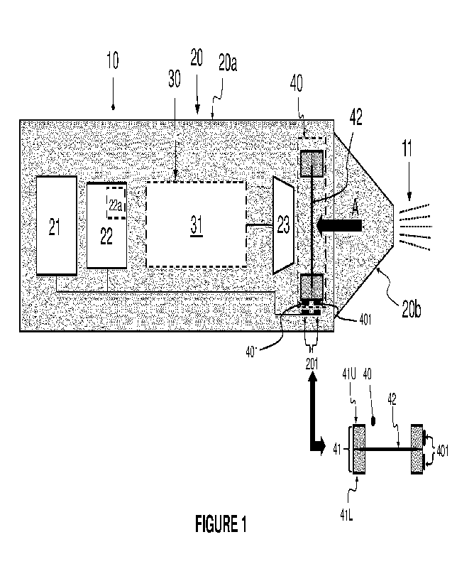
Figure 1 is a schematic view of a first example of an aerosol-generating
system 10. The
aerosol-generating system 10 is a smoking system for generating an inhalable
aerosol 11. The
system 10 has an elongate housing 20, a cartridge 30 and an aerosolisation
module 40. For the
example shown and described, the elongate housing 20 is generally cylindrical
and is formed of
a polymer material. The cartridge 30 is detachably receivable within the
elongate housing 20, as
will be described in more detail in the following paragraphs. Similarly, for
the example shown in
figure 1, the aerosolisation module 40 is also detachably receivable within
the housing 20. The
cartridge 30 and aerosolisation module 40 are replaceable components of the
aerosol-generating
system 10. Consequently, the elongate housing 20 is reusable with different
aerosolisation
CA 03209490 2023- 8- 23
WO 2022/179854 PCT/EP2022/053160
16
modules 30 and cartridges 40. When the cartridge 30 and aerosolisation module
40 are
assembled within the elongate housing 20, the combination of the housing,
cartridge and
aerosolisation module collectively forms an aerosol-generating device.
The elongate housing 20 contains a power source 21, a controller 22 and a
liquid feed
assembly 23. The elongate housing 20 has a cylindrical portion 20a and a
mouthpiece portion
20b. The mouthpiece portion 20b is fitted to one end of the cylindrical
portion 20a to form a mouth
end of the elongate housing 20. The power source 21 is coupled to the
controller 22 to provide
power thereto. For the example shown, the power source 21 is a rechargeable
battery, which
serves as a source of electrical power. For the example shown and described,
the controller 22
takes the form of control electronics. The controller 22 also incorporates a
memory module 22a
containing instructions accessible by a processor (not shown) of the
controller so as to control
operation of the aerosolisation module 40. The controller 22 is configured to
generate an
electrical driving signal which is conveyed, along wiring or similar
electrically-conductive
members, to electrically-conductive contacts 201 within the housing 20. The
electrically-
conductive contacts 201 of the housing 20 detachably interface with
corresponding electrically-
conductive contacts 401 of the aerosolisation module 40. The nature of various
exemplary
interfaces between the corresponding electrically-conductive contacts 201, 401
of the housing 20
and the aerosolisation module 40 is described in the following paragraphs.
The cartridge 30 contains a reservoir 31 of liquid aerosol-forming substrate.
The liquid
aerosol-forming substrate contains nicotine. When the cartridge 30 is received
in the elongate
housing 20, the cartridge is fluidically coupled to the liquid feed assembly
23. The liquid feed
assembly 23 has the form of a wicking material extending between the cartridge
30 and the
aerosolisation module 40 so as to progressively feed liquid aerosol-forming
substrate from the
reservoir 31 to the aerosolisation module. In an alternative example (not
shown), the liquid feed
assembly 23 is a pump powered by the power source 21. In a further alternative
example (not
shown), the liquid feed assembly 23 forms part of the cartridge 30.
The aerosolisation module 40 has a vibratable transducer 41 and a membrane 42.
The
vibratable transducer 41 has a pair of annular piezo-electric actuator
assemblies 41U, 41L. The
annular actuator assemblies 41U, 41L are coupled to opposing surfaces of the
membrane 42 to
secure an annulus of the membrane there between. Each annular actuator
assembly 41U, 41L
is formed of a single ring-shaped single piezo-actuator. In an alternative
example (not shown),
each annular actuator assembly 41U, 41L is instead formed of two or more piezo-
actuators
coupled together and arranged circumferentially to collectively define a ring-
shaped form. In a
further alternative example (not shown), the vibratable transducer 41 has a
single piezo-electric
actuator assembly; for example, one of assembly 41U, 41L.
When the aerosolisation module 40 is received in the elongate housing 20, the
electrically-
conductive contacts 201 of the housing 20 are in contact and electrical
communication with the
CA 03209490 2023- 8- 23
WO 2022/179854
PCT/EP2022/053160
17
electrically-conductive contacts 401 of the aerosolisation module 40. As
illustrated schematically
in figure 1 and as is clear from the preceding paragraphs, electrical contact
between the
corresponding contacts 201, 401 of the housing 20 and the aerosolisation
module 40 is non-
permanent so that the aerosolisation module may be removed from the housing.
This allows the
aerosolisation module 40 to be re-inserted or swapped with a replacement
aerosolisation module
(as indicated by the double-headed arrow in figure 1). Although not shown in
the figures, the
replacement aerosolisation module may be adapted to generate an aerosol
emission pattern
which is different to that generated by the original aerosolisation module.
Figure 2 shows a plan view of the membrane 42 of the aerosolisation module 40,
i.e. when
viewed in the direction of arrow A of figure 1. For convenience, the pair of
annular actuator
assemblies 41U, 41L are excluded from figure 2. In the example shown and
described, the
membrane 42 is formed of a polymer material. However, as described above,
other materials
may be selected for the membrane 42, with the membrane material being one
which has minimal
to zero chemical reactivity with the composition of the liquid aerosol-forming
substrate. The
membrane 42 is circular in plan view to correspond with the annular nature of
the actuator
assemblies 41U, 41L. However, in alternative examples (not shown) the membrane
42 may be
any other shape when viewed in plan, such as rectangular. The membrane 42 has
an aerosol-
generation zone 43 (the periphery of which is represented by a broken line in
figure 2). The
aerosol generation zone 43 is provided with a plurality of nozzles 44
(represented by a pattern of
dots in figure 2). The nozzles 44 are in the form of holes extending through
the thickness of the
membrane 42. An annular gap 45 is present between the periphery of the
membrane 42 and the
periphery of the aerosol generation zone 43. The annular gap 45 provides space
to enable the
upper and lower annular actuator assemblies 41U, 41L to press against opposing
surfaces of the
membrane 42. The terms "upper" and "lower" are used only in a relative sense
so as to describe
the location of the actuator assemblies 41U, 41L relative to each other and
the membrane 42.
Figures 3a and 3b show perspective views of a first example of the
aerosolisation
module 40. Figure 4 illustrates how the aerosolisation module 40 of figures
3a,b is positioned
between cylindrical portion 20a and mouthpiece portion 20b of the elongate
housing 20 so as to
provide a detachable electrical connection between the housing 20 and the
aerosolisation
module 40.
The electrically-conductive contacts 401 of the aerosolisation module 40 of
figures 3a,b are
formed of electrically-conductive plates 401pL, 401pu, 401nL, 401nu defined on
the lowermost
surface of the lower actuator assembly 41L. Plates 401pL and 401nL are
connected to
electrodes 46L of the lower actuator assembly 41L. Plates 401pL, 401nL and
electrodes 46L serve
to deliver the electrical driving signal generated by the controller 22 to the
lower actuator
assembly 41L of the vibratable transducer 41. Plates 401pu, 401nu each connect
to a metallic
core 47. Each metallic core 47 vertically extends from its respective plate
401pu, 401nu along
CA 03209490 2023- 8- 23
WO 2022/179854 PCT/EP2022/053160
18
the height of the aerosolisation module 40 to connect with electrodes 46U of
the upper actuator
assembly 41U. The plates 401pu, 401nu, their corresponding metallic
cores 47 and
electrodes 46U serve to deliver the electrical driving signal generated by the
controller 22 to the
upper actuator assembly 41U of the vibratable transducer 41. For the example
of figures 3a,b,
the electrically-conductive plates 401L, 401pu, 401nL, 401nu are all provided
on a common face
of the aerosolisation module 40, namely the lowermost surface of the
aerosolisation module. For
the example shown, the plates 401pL, 401pu, 401nL, 401nu are formed of metal.
As shown in figure 4, a recessed annular seat 24 is defined at one end of the
cylindrical
portion 20a of the elongate housing 20. The electrically-conductive contacts
201 have the form
of electrically-conductive spring-loaded pin connectors 201L, 201pu, 201nL,
201nu which
protrude from the base 25 of the seat 24. Pin connectors 201pL and 201nL are
associated with
the electrical driving signal for the lower actuator assembly 41L. Pin
connectors 201pu and 201nu
are associated with the electrical driving signal for the upper actuator
assembly 41U. In use, the
aerosolisation module 40 would be placed in the seat 24 so that the lowermost
surface of the
aerosolisation module rests on the base 25 of the seat. When the
aerosolisation module 40 is
positioned in the seat 24, the pin connectors 201pL, 201nL press against the
corresponding
surfaces of plates 401pL, 401nL, and pin connectors 201pu, 201nu press against
the
corresponding surfaces of plates 401pu, 401nu. One end of the mouthpiece
portion 20b of the
housing 20 is formed with an annular step 26 corresponding to the annular seat
24. The
mouthpiece portion 20b is mated with the cylindrical portion 20a so that the
annular step 26
locates in the seat 24 and presses down on the uppermost surface of the
aerosolisation
module 40. Mechanical means (not shown) are provided to secure the cylindrical
portion 20a and
mouthpiece portion 20b together. By way of example (not shown), corresponding
faces of the
cylindrical portion 20a and mouthpiece portion 2b may be correspondingly
threaded to define a
screw fit, or alternatively may be profiled to define a bayonet fit between
the two portions 20a,b.
In a further alternative (not shown), the corresponding faces of the
cylindrical portion 20a and
mouthpiece portion 20b may include respective magnets of opposite polarity
such that the
portions 20a, 20b are magnetically attracted to each other.
When the mouthpiece portion 20b is secured to the cylindrical portion 20a, the
lowermost
surface of the aerosolisation module 40 would be firmly pressed against the
base 25 of the seat 24
to depress pin connectors 201pL, 201pu, 201nL, 201nu into recesses (not shown)
provided in the
base 25. The spring-loaded nature of the connectors 201pL, 201pu, 201nL, 201nu
helps to urge
the connectors against the surface of the corresponding plates 401pL, 401pu,
401nL, 401nu of the
aerosolisation module 40. In an alternative example (not shown), the
aerosolisation module 40
and the seat 24 are provided with indexing features to provide a predetermined
alignment
between the aerosolisation module 40 and the seat 24. Such indexing features
may help to
ensure that the connectors 201pL, 201pu, 201nL, 201nu electrically interface
with their
CA 03209490 2023- 8- 23
WO 2022/179854 PCT/EP2022/053160
19
corresponding plates 401pL, 401pu, 401nL, 401nu. Examples of suitable indexing
features include
mating lugs and recesses on the aerosolisation module 40 and the seat 24.
In use, the controller 22 accesses the memory module 22a and generates the
electrical
driving signal which is conveyed along the internal wiring or similar to the
electrically-conductive
contacts 201 of the housing 20, namely pin connectors 201L, 201pu, 201nL,
201nu. As the pin
connectors 201L, 201pu, 201nL, 201nu are in contact with the corresponding
electrically
conductive plates 401pL, 401pu, 401nL, 401nu of the aerosolisation module 40,
the electrical
driving signal is conveyed to the upper and lower actuator assemblies 41U,
41L. In this manner,
the elongate housing 20 is electrically coupled to the aerosolisation module
40, with the electrical
driving signal fed to the upper and lower actuator assemblies 41U, 41L to
induce vibration thereof.
Vibratory output from the upper and lower actuator assemblies 41U, 41L induces
vibration of the
membrane 42. Liquid aerosol-forming substrate is drawn from the reservoir 31
by the liquid
feed 23 to the lower surface of the membrane 42. The vibrating action of the
membrane 42 results
in the substrate being ejected through the nozzles 44 as a pattern of aerosol
droplets.
Figures 5a and 5b show perspective views of a second example of the
aerosolisation
module 40. Figure 6 illustrates the aerosolisation module 40 of figures 5a,b
positioned in a
cradle 50. The cradle 50 can slide in and out of the elongate housing 20 to
provide detachable
electrical connection between the housing 20 and the aerosolisation module 40.
Figure 7
provides a cross-section view through section B-B of figure 6 when the cradle
50 is fully inserted
inside the housing 20.
The electrically-conductive contacts 401 of the aerosolisation module 40 of
figures 5a,b are
formed of electrically-conductive plates 401pL, 401pu, 401nL, 401nu. However,
in contrast to the
aerosolisation module 40 of figures 3a,b, for the module of figures 5a,b the
electrically conductive
plates 401pL, 401nL associated with the lower actuator assembly 41L and the
electrically-
conductive plates 401pu, 401nu associated with the upper actuator assembly 41U
are formed on
opposing surfaces of the vibratable transducer 41. The electrically conductive
plates 401 PL, 401nL
are arranged on the lowermost surface of the lower actuator assembly 41L,
whereas the
electrically-conductive plates 401pu, 401nu are arranged on the uppermost
surface of the upper
actuator assembly 41U. The plates 401pL, 401nL are connected to electrodes 46L
of the lower
actuator assembly 41L. Similarly, plates 401pu and 401nu are connected to
electrodes 46U of
the upper actuator assembly 41U. The plates 401pL, 401nL and electrodes 46L
serve to deliver
the electrical driving signal generated by the controller 22 to the lower
actuator assembly 41L of
the vibratable transducer 41. Similarly, the plates 401pu, 401nu and
electrodes 46U serve to
deliver the electrical driving signal generated by the controller 22 to the
upper actuator
assembly 41L of the vibratable transducer 41. For the example shown, the
plates 401pL, 401pu,
401nL, 401nu are formed of metal.
CA 03209490 2023- 8- 23
WO 2022/179854 PCT/EP2022/053160
As shown in figure 6, an aperture 27 is formed in the sidewall of the
cylindrical portion 20a
of the housing 20. The aperture 27 defines an access opening for the cradle
50. The
aerosolisation module 40 is positioned in the cradle 50. In an alternative
example (not shown),
the aerosolisation module 40 and the cradle 50 are provided with indexing
features to provide a
5
predetermined alignment between the aerosolisation module 40 and the cradle.
Examples of
suitable indexing features include mating lugs and recesses on the
aerosolisation module 40 and
the cradle 50.
The cradle 50 is slidably insertable into the housing 20 as shown in figures 6
and 7. The
cradle 50 is provided with lugs 51 (see figure 7). When the cradle 50 is slid
out from the
10
housing 20, the lugs 51 react against the inner surface of the sidewall of
the housing 20, thereby
preventing uncoupling of the cradle 50 from the housing 20. The electrically-
conductive
contacts 201 of the housing 20 take the form of pairs of sprung-loaded
connectors 201pL, 201nL
and 201põ, 201nu. Only one connector of each pair is visible in the view of
figure 7. Each of the
connectors 201L, 201nL, 201pu, 201nu has an arm 202 extending from a root,
with a spring 203
15
provided at the root so as to bias the connectors towards upper and lower
surfaces of the
aerosolisation module 40. Each pair of connectors 201pL, 201nL and 201pu,
201nu are connected
to the controller 22 by electrical wiring or similar. Connectors 201pL, 201nL
are associated with
providing the electrical driving signal generated by controller 22 to the
lower actuator
assembly 41L. Connectors 201pu, 201nu are associated with providing the
electrical driving
20
signal to the upper actuator assembly 41U. When the cradle 50 holding the
aerosolisation
module 40 is slid inside the housing 20, the lower pair of connectors 201pL,
201nL are urged by
the springs 203 against the electrically-conductive plates 401L, 401nL of the
lower actuator
assembly 41L and the upper pair of connectors 201pu, 201nu are similarly urged
against
electrically-conductive plates 401pu, 401nu of the upper actuator assembly
41U.
In use, the controller 22 accesses the memory module 22a and generates the
electrical
driving signal which is conveyed along the internal wiring or similar to the
electrically-conductive
contacts 201 of the housing 20, namely to the pairs of sprung-loaded
connectors 201pL, 201nL
and 201pu, 201nu. The upper pair of connectors 201pu, 201nu are urged against
the plates 401pu,
401nu. The lower pair of connectors 201 PL, 201nL are urged against the plates
401pL, 401nL. In
this manner, the elongate housing 20 is electrically coupled to the
aerosolisation module 40, with
the electrical driving signal fed to the upper and lower actuator assemblies
41U, 41L to induce
vibration thereof. Vibratory output from the upper and lower actuator
assemblies 41U, 41L
induces vibration of the membrane 42. Liquid aerosol-forming substrate is
drawn from the
reservoir 31 by the liquid feed 23 to the lower surface of the membrane 42.
The vibrating action
of the membrane 42 results in the substrate being ejected through the nozzles
44 as a pattern of
aerosol droplets.
CA 03209490 2023- 8- 23
WO 2022/179854 PCT/EP2022/053160
21
Figure 8 is a third example of an aerosolisation module 40, with figure 8
being a plan view
of the membrane 42. The aerosolisation module 40 of figure 8 has a vibratable
transducer 41 in
the form of a single actuator assembly which is positioned against one surface
of membrane 42.
The membrane 42 has a first membrane portion 42a and a second membrane portion
42b, each
membrane portion formed of metal. The first and second membrane portions 42a,
42b are
electrically insulated from each other by an insulating strip 48. Region 401p
of membrane
portion 42a serves as an electrical contact region. Similarly, region 401n of
membrane
portion 42b also serves as an electrical contact region. Electrodes 46 are
connected to regions
401p, 401n. In use, the electrically-conductive contacts 201 of the elongate
housing 20 would
contact the regions 401p, 401n to feed the electrical driving signal from the
controller 22 to the
vibratable transducer 41 of the aerosolisation module 40. The insulating strip
43 avoids a short
circuit between regions 401p, 401n.
Figure 9 is a schematic view of a second example of an aerosol-generating
system 10.
Features in common with the exemplary system of figure 1 are referred to using
like-reference
signs. The aerosol-generating system 10 of figure 9 differs from the system of
figure 1 in that the
controller 22 forms part of the aerosolisation module 40. As seen in figure 9,
the controller 22 is
coupled to a peripheral side surface of the vibratable transducer 41, with the
electrically-
conductive contacts 401 of the aerosolisation module coupled to or provided on
a surface of the
controller. When the aerosolisation module 40 is received in the elongate
housing 20, the
electrically-conductive contacts 201 of the housing 20 are in contact and
electrical communication
with the electrically-conductive contacts 401.
For the purpose of the present description and of the appended claims, except
where
otherwise indicated, all numbers expressing amounts, quantities, percentages,
and so forth, are
to be understood as being modified in all instances by the term "about". Also,
all ranges include
the maximum and minimum points disclosed and include any intermediate ranges
therein, which
may or may not be specifically enumerated herein. In this context, therefore,
a number "A" is
understood as "A" 10% of "A". Within this context, a number "A" may be
considered to include
numerical values that are within general standard error for the measurement of
the property that
the number "A" modifies. The number "A", in some instances as used in the
appended claims,
may deviate by the percentages enumerated above provided that the amount by
which "A"
deviates does not materially affect the basic and novel characteristic(s) of
the claimed invention.
Also, all ranges include the maximum and minimum points disclosed and include
any intermediate
ranges therein, which may or may not be specifically enumerated herein.
CA 03209490 2023- 8- 23