Note: Descriptions are shown in the official language in which they were submitted.
WO 2022/186894
PCT/US2021/070936
LIGHT FIELD DEVICE AND VISION-BASED TESTING SYSTEM USING SAME
CROSS REFERENCE TO RELATED APPLICATIONS
[0001] This application is a continuation-in-part of U.S. Patent
Application No.
17/309,133 filed April 29, 2021. which is a US national stage of International
Application
No. PCT/M2020/057887 filed August 22, 2020, which claims priority to, and is a
continuation of, U.S. Patent Application No. 16/810,143 filed March 5, 2020
and issued as
U.S. Patent No. 10,761,604 on September 1, 2020. International Application No.
PCT/M2020/057887 also claims priority to U.S. Provisional Application No.
62/929,639
filed November 1, 2019.
[0002] This application is also a continuation-in-part of U.S. Patent
Application No.
17/302,392 filed April 30, 2021, which is a continuation-in-part of
International
Application No. PCT/US2020/058392 filed October 30, 2020.
[0003] This application also claims priority to U.S. Provisional
Application No.
63/200,433 filed March 5, 2021, to U.S. Provisional Application No. 63/179,057
filed April
23, 2021, and to U.S. Provisional Application No. 63/179,021 filed April 23,
2021.
[0004] The entire disclosure of each of the above-referenced
applications is hereby
incorporated herein by reference.
FIELD OF THE DISCLOSURE
[0005] The present disclosure relates to digital displays and,
in particular, to a light
field device and vision-based testing system using same.
BACKGROUND
[0006] Refractive errors such as myopia, hyperopia, and
astigmatism affect a large
segment of the population irrespective of age, sex and ethnic group. If
uncorrected, such
errors can lead to impaired quality of life. One method to determine the
visual acuity of a
person is to use a phoropter to do a subjective vision test (e.g. blur test)
which relies on
1
CA 03209939 2023- 8- 25
WO 2022/186894
PCT/ITS2021/070936
feedback from the subject. The phoropter is used to determine the refractive
power needed
to bring any projected image to focus sharply onto the retina. A traditional
phoropter is
usually coupled with a screen or a chart where optotypes are presented, for
example a
Snellen chart. A patient is asked to look through the instrument to a chart
placed at optical
infinity, typically equivalent to 6m/20feet. Then he/she will be asked about
the
letters/symbols presented on the screen, and whether he/she is able to
differentiate/resolve
the letters. The patient will keep looking at letters of smaller size or
higher resolution power
until there is no improvement, at that time the eye-care practitioner is able
to determine the
visual acuity (VA) of the subject and proceed with the other eye.
[0007] There also
exists a range of physiological conditions that are indirectly related
to the visual system of a patient, and which may be screened for, observed or
otherwise
detected by testing said visual system. One such physiological condition is
cognitive
impairment. The Centers for Disease Control estimates that more than 1.6
million people
in the United States suffer a concussion - or traumatic brain injury - every
year. It was once
assumed that the hallmark of a concussion was a loss of consciousness. More
recent
evidence, however, does not support that. The majority of people diagnosed
with a
concussion do not experience any loss of consciousness. The most common
immediate
symptoms are amnesia and confusion. Since the visual system of a person is a
relatively
easily accessible part of the nervous system, it may be used to evaluate
possible brain injury
resulting from a concussion or similar. Indeed, the visual system involves
half of the brain
circuits and many of them are vulnerable to head injury. Traditionally, vision
has not been
properly used as a diagnostic tool, but a more careful analysis could provide
a powerful
tool to save precious time in the diagnosis and early treatment. For example,
post-
concussion syndrome (PCS) involves a constellation of symptoms and/or signs
that
commonly follow traumatic brain injury (TB I). After a concussion, the
oculomotor control,
or eye movement, may be disrupted. Examining the oculomotor system may thus
provide
valuable information in evaluating the presence or degree of cognitive
impairment, for
example caused by a concussion or similar.
[0008]
Light field displays are known to adjust a user's perception of an input
image
by adjusting a light field emanated by the display so to control how a light
field image is
CA 03209939 2023- 8- 25
WO 2022/186894
PCT/ITS2021/070936
ultimately projected for viewing. For instance, in some examples, users who
would
otherwise require corrective eyevvear such as glasses or contact lenses, or
again bifocals,
may consume images produced by such devices in clear or improved focus without
the use
of such eyewear. Other light field display applications, such as 3D displays,
are also known.
[0009] This
background information is provided to reveal information believed by the
applicant to be of possible relevance. No admission is necessarily intended,
nor should be
construed, that any of the preceding information constitutes prior art or
forms part of the
general common knowledge in the relevant art.
SUMMARY
[0010] The
following presents a simplified summary of the general inventive
concept(s) described herein to provide a basic understanding of some aspects
of the
disclosure. This summary is not an extensive overview of the disclosure. It is
not intended
to restrict key or critical elements of embodiments of the disclosure or to
delineate their
scope beyond that which is explicitly or implicitly described by the following
description
and claims.
[0011]
A need exists for light field device and vision-based testing system using
same
that overcome some of the drawbacks of known techniques, or at least, provides
a useful
alternative thereto.
[0012]
In accordance with one aspect, there is provided a binocular vision-based
testing
device for digitally implementing a vision-based test for a user using both
their left and
right eye simultaneously, the device comprising: left and right digital
display portions
comprising respective pixel arrays; corresponding light field shaping layer
(LFSL) portions
comprising respective light field shaping element (LFSE) arrays disposed at a
distance
from said respective pixel arrays to shape a respective left and right light
field emanating
therefrom; a digital data processor operable on pixel data for vision-based
test content to
output adjusted pixel data to be simultaneously rendered via said respective
pixel arrays
and LFSE arrays in accordance with a designated user perception adjustment and
projected
within respective predominant left and right light field view zones formed
thereby along
3
CA 03209939 2023- 8- 25
WO 2022/186894
PCT/US2021/070936
respective optical paths to respective left and right optical outputs while
concurrently
projecting at least some same vision-based test content within adjacent left
and right view
zones, respectively; wherein projection of said adjacent left and right view
zones toward
said right and left optical outputs is optically obstructed from interfering
with user viewing
of said predominant right and left light field view zones, respectively.
[0013] In one embodiment, a distance between a center of said
left and right digital
display portions is greater than an interpupillary distance resulting in an
initial separation
between said respective predominant left and right light filed view zones also
being greater
than said interpupillary distance, wherein said left and right optical outputs
are disposed so
to substantially correspond with said interpupillary distance, and wherein the
device further
comprises respective mirror assemblies disposed along said respective left and
right optical
paths to non-refractively narrow said initial separation substantially in line
with said
interpupillary distance thereby substantially aligning said left and right
light field view
zones with said left and right optical outputs.
[0014] In one embodiment, the left and right optical outputs and said
respective mirror
assemblies are adjustable to accommodate different interpupillary distances.
[0015] In one embodiment, the mirror assemblies comprise
periscope-like assemblies.
[0016] In one embodiment, the vision-based test content is to be
simultaneously
perceived by the left and right eye via said left and right optical outputs to
be at a common
virtual position relative thereto.
[0017] In one embodiment, the common virtual position comprises
a virtual depth
position relative to said display portions.
[0018] In one embodiment, the designated user perception
adjustment comprises
respective left and right vision correction adjustments.
[0019] In one embodiment, the left and right display portions comprise
respective
displays, and wherein said respective LFSL portions comprise respective
microlens arrays.
4
CA 03209939 2023- 8- 25
WO 2022/186894
PCT/ITS2021/070936
[0020] In one embodiment, the projection of said adjacent left
and right view zones is
optically obstructed by a physical barrier.
[0021] In one embodiment, the digital data processor is operable
to adjust rendering of
said vision-based test content via said respective LFSL portions so to
accommodate for a
visual aberration in at least one of a user's left or right eye.
[0022] In one embodiment, the visual aberration comprises
distinct respective visual
aberrations for the left and right eye.
[0023] In one embodiment, the vision-based test comprises a
visual acuity test to
determine an optimal user perception adjustment corresponding with a reduced
user visual
acuity level in prescribing corrective eyewear or surgery for each of the
user's left and right
eye.
[0024] In one embodiment, the vision-based test is first
implemented for each eye
separately in identifying a respective optimal user perception adjustment
therefor, and
wherein both said respective optimal user perception adjustment are then
validated
concurrently via binocular rendering of said vision-based content according to
each said
respective optimal user perception adjustment.
[00251 In one embodiment, the device is a refractor or a
phoropter.
[0026] In one embodiment, the vision-based test comprises a
cognitive impairment test
to determine a physiological user response to a designated set of binocular
user perception
adjustments.
[0027] In one embodiment, the device further comprises
respective optical view zone
isolators disposed along said respective optical paths between said LFSL
portions and said
respective left and right optical outputs to at least partially obstruct
visual content projected
within said adjacent left and right view zones from interfering with visual
content projected
within said predominant left and right view zones, respectively.
5
CA 03209939 2023- 8- 25
WO 2022/186894
PCT/ITS2021/070936
[0028] In one embodiment, each of said optical view zone
isolators defines a view zone
isolating aperture dimensioned and disposed so to at most substantially
correspond with a
cross section of said predominant view zones.
[00291 In one embodiment, the hardware processor is operable to
adjust said adjusted
pixel data to adjust said designated user perception adjustment within a
designated range,
wherein the device further comprises an adjustable refractive optical system
interposed
between said LFSL portions and said respective optical outputs to shift said
designated
range in extending an overall range of the device, and wherein said respective
view zone
isolators are disposed between said LFSL portions and said adjustable
refractive optical
system so to at least partially obstruct projection of said adjacent view
zones through said
adjustable refractive optical system.
[0030] In one embodiment, the adjustable refractive optical
system comprises
respective tunable lenses or respective lenses selectable from respective
arrays of selectable
lenses.
[0031] In one embodiment, the hardware processor is operable to adjust said
adjusted
pixel data to adjust said designated user perception adjustment within a
designated range,
wherein the device further comprises an adjustable refractive optical system
interposed
between said LFSL portions and said respective optical outputs to shift said
designated
range in extending an overall range of the device, and wherein the device
further comprises
an optical assembly to optically transfer respective exit plane light fields
of said adjustable
refractive optical element to said respective optical outputs.
[0032] In one embodiment, the optical assembly comprises
respective left and right
telescope-like assemblies.
[0033] In one embodiment, the telescope-like assemblies optimize
at least one of the
following light field parameters at the optical outputs: exit aperture, field
of view (FoV),
and/or angular resolution.
[0034] In one embodiment, the telescope-like assemblies define
Keplerian-type
assemblies each comprising an input lens disposed along said respective
optical path at an
6
CA 03209939 2023- 8- 25
WO 2022/186894
PCT/ITS2021/070936
input lens focal distance downstream from said adjustable refractive optical
system to
receive said exit plane light field therefrom, and an output lens disposed
along said
respective optical path at an output lens focal distance upstream of the
respective optical
output.
[0035] In one
embodiment, the telescope-like assemblies define Galilean-type
telescope assemblies each comprising an input lens disposed along said
respective optical
path an input lens focal distance upstream of said adjustable refractive
optical system, and
an output lens disposed along said respective optical path an output lens
distance
downstream of said adjustable refractive optical system.
[0036] In
accordance with another aspect, there is provided a device operable to
dynamically adjust user perception of visual content via an optical output
thereof, the
device comprising: an array of digital display pixels for rendering the visual
content to be
viewed via the optical output; a light field shaping layer (LFSL) comprising a
corresponding array of light field shaping elements (LFSEs) disposed at a
distance from
said digital display pixels to shape a light field emanated therefrom along an
optical path
formed with the optical output, wherein said LFSL is positioned so to
optically project at
least some of the visual content within a predominant view zone along the
optical path and
aligned with the optical output, while concurrently projecting at least some
same visual
content within an adjacent view zone; and a hardware processor operable on
input pixel
data for the visual content to output adjusted pixel data to be rendered via
said LFSEs in
accordance with a designated user perception within said predominant view zone
such that
the visual content, when so rendered in accordance with said adjusted pixel
data, is
projected via said LFSEs to produce said designated user perception of the
visual content
when viewed via the optical output; an optical view zone isolator disposed
along said
optical path between said LFSL and the optical output to at least partially
obstruct visual
content projected within said adjacent view zone from interfering with visual
content
projected within said predominant view zone at the optical output.
7
CA 03209939 2023- 8- 25
WO 2022/186894
PCT/ITS2021/070936
[0037]
In one embodiment, the optical view zone isolator defines a view zone
isolating
aperture dimensioned and disposed so to at most substantially correspond with
a cross
section of said predominant view zone.
[00381
In one embodiment, the hardware processor is operable to adjust said
adjusted
pixel data to adjust said designated user perception within a designated
range, wherein the
device further comprises an adjustable refractive optical system interposed
between said
LFSL and the optical output to shift said designated range in extending an
overall range of
the device, and wherein said view zone isolator is disposed between said LFSL
and said
adjustable refractive optical system so to at least partially obstruct
projection of said
adjacent view zone through said adjustable refractive optical system.
[0039]
In one embodiment, the adjustable refractive optical system comprises at
least
one of a tunable lens or a lens selectable from an array of selectable lenses.
[00401
In accordance with another aspect, there is provided a subjective eye test
device
comprising: an array of digital display pixels; and a light field shaping
layer (LFSL)
comprising a corresponding array of light field shaping elements (LFSEs)
disposed at a
distance from said digital display pixels to shape a light field emanated
therefrom along an
optical path formed with the optical output, wherein said LFSL is positioned
so to optically
project rendering of at least one optotype within a predominant view zone
along the optical
path and aligned with the optical output, while concurrently projecting at
least some same
said at least one optotype within an adjacent view zone; an optical view zone
isolator
disposed along said optical path between said LFSL and the optical output to
at least
partially obstruct said adjacent view zone from interfering with said
predominant view zone
at the optical output; and a hardware processor operable on input pixel data
for the at least
one optotype to output adjusted pixel data to be rendered via said LFSEs in
accordance
with a designated vision correction parameter within said predominant view
zone such that
said at least one optotype, when so rendered in accordance with said adjusted
pixel data, is
projected via said LFSEs to at least partially accommodate for a reduced
visual acuity
condition corresponding to said designated vision correction parameter when
viewed via
the optical output, wherein said hardware processor is further operable to
adjust said
8
CA 03209939 2023- 8- 25
WO 2022/186894
PCT/ITS2021/070936
designated vision correction parameter to accommodate for a distinct reduced
visual acuity
condition until an optimal vision correction parameter is identified.
[0041] In one embodiment, the hardware processor is operable to
adjust said adjusted
pixel data to adjust said designated vision correction parameter within a
designated range,
wherein the device further comprises an adjustable refractive optical system
interposed
between said LFSL and the optical output to shift said designated range in
extending an
overall range of the device, and wherein said view zone isolator is disposed
between said
LFSL and said adjustable refractive optical system so to at least partially
obstruct
projection of said adjacent view zone through said adjustable refractive
optical system.
[0042] In accordance with another aspect, there is provided a device
operable to
dynamically adjust user perception of visual content via an optical output
thereof associated
with a user eye location, the device comprising: an array of digital display
pixels for
rendering the visual content to be viewed via the optical output; a light
field shaping layer
(LFSL) comprising a corresponding array of light field shaping elements
(LFSEs) disposed
at a distance from said digital display pixels to shape a light field emanated
therefrom along
an optical path formed with the optical output; a hardware processor operable
on input
pixel data for the visual content to output adjusted pixel data to be rendered
via said LFSEs
in accordance with a designated user perception such that the visual content,
when so
rendered in accordance with said adjusted pixel data, is projected via said
LFSEs to produce
said designated user perception of the visual content when viewed via the
optical output,
wherein said hardware processor is operable to adjust said adjusted pixel data
to adjust said
designated user perception within a designated dioptric range; an adjustable
refractive
optical element interposed between said LFSL and the optical output to shift
said
designated dioptric range in extending an overall dioptric range of the
device; and an
optical assembly disposed along said optical path to optically transfer an
exit plane light
field of said adjustable refractive optical element to the optical output and
user eye location.
[0043] In one embodiment, the optical assembly comprises a
telescope-like assembly.
[0044] In one embodiment, the optical assembly further magnifies
or de-magnifies said
light field at the optical output.
9
CA 03209939 2023- 8- 25
WO 2022/186894
PCT/ITS2021/070936
[0045]
In one embodiment, the telescope-like assembly optimizes at least one of
the
following light field parameters at the optical output: exit aperture, field
of view (FoV),
and/or angular resolution.
[00461
In one embodiment, the telescope-like assembly defines a Keplerian-type
assembly comprising an input lens disposed along said optical path at an input
lens focal
distance downstream from said adjustable refractive optical element to receive
said exit
plane light field therefrom, and an output lens disposed along said optical
path at an output
lens focal distance upstream of the optical output.
[0047]
In one embodiment, the telescope-like assembly defines a Galilean-type
telescope assembly comprising an input lens disposed along said optical path
an input lens
focal distance upstream of said adjustable refractive optical element, and an
output lens
disposed along said optical path an output lens distance downstream of said
adjustable
refractive optical element.
[0048]
In accordance with another aspect, there is provided a device operable to
render
distinct portions of visual content in accordance with respective designated
visual
perception adjustments, the device comprising: an array of digital display
pixels; a
corresponding array of light field shaping elements (LFSEs) disposed at a
distance from
said digital display pixels to shape a light field emanated therefrom; and a
hardware
processor operable to associate a respective subset of the display pixels with
each of the
distinct portions, and further operable on input pixel data for each of the
distinct portions
to output respectively adjusted pixel data therefor in accordance with a
respective
designated visual perception adjustment associated therewith, such that each
of the distinct
portions, when rendered according to said respectively adjusted pixel data via
said
respective subset of the display pixels, is projected via said LFSEs such that
each of the
portions are effectively viewed concurrently in accordance with their
respective designated
visual perception adjustment.
[0049]
In one embodiment, the hardware processor is operable to simultaneously
render said respectively adjusted pixel data for each of the distinct portions
via each said
respective distinct subset of the display pixels.
CA 03209939 2023- 8- 25
WO 2022/186894
PCT/ITS2021/070936
[0050] In one embodiment, the hardware processor is operable to
alternatingly render
said respectively adjusted pixel data for each of the distinct portions via
each said
respective distinct subset of the display pixels.
[00511 In one embodiment, the hardware processor is operable to
alternatingly render
said respectively adjusted pixel data at a frequency beyond a visible flicker
frequency.
[0052] In one embodiment, the respective designated visual
perception adjustments
comprise respective perceived image portion depths.
[0053] In one embodiment, the respective designated visual
perception adjustments
correspond with respective visual aberration correction parameters, and
wherein said
hardware processor is further operable to dynamically adjust said respective
visual
aberration correction parameters for comparative purposes until an optimal
visual
aberration corrective parameter is identified in prescribing corrective
eyewear or surgery.
[0054] In one embodiment, the distinct portions are rendered in
accordance with said
respective visual aberration correction parameters in respective quadrants of
said digital
display.
[0055] In accordance with another aspect, there is provided a
device operable to render
distinct portions of visual content in accordance with respective designated
visual
perception adjustments, the device comprising: an array of digital display
pixels; a
corresponding array of light field shaping elements (LFSEs) disposed at a
distance from
said digital display pixels to shape a light field emanated therefrom; a
hardware processor
operable on input pixel data for each of the distinct portions to output
respectively adjusted
pixel data therefor in accordance with a respective designated visual
perception adjustment
associated therewith, such that each of the distinct portions, when rendered
according to
said respectively adjusted pixel data, is projected via said LFSEs to produce
said respective
designated visual perception adjustment accordingly, wherein said hardware
processor is
operable to alternatingly render said respectively adjusted pixel data for
each of the distinct
portions beyond a visible flicker frequency such that each of the portions are
effectively
11
CA 03209939 2023- 8- 25
WO 2022/186894
PCT/ITS2021/070936
viewed concurrently in accordance with their respective designated visual
perception
adjustment.
[0056] In one embodiment, the respective designated visual
perception adjustments
comprise respective perceived image portion depths.
[0057] In one embodiment, the respective designated visual perception
adjustments
correspond with respective visual aberration correction parameters, and
wherein said
hardware processor is further operable to dynamically adjust said respective
visual
aberration correction parameters for comparative purposes until an optimal
visual
aberration corrective parameter is identified in prescribing corrective
eyewear or surgery.
[0058] In one embodiment, the distinct portions are rendered in accordance
with said
respective visual aberration correction parameters in respective quadrants of
said digital
display.
[0059] In accordance with another aspect, there is provided a
computer-implemented
method, automatically implemented by one or more digital processors, to adjust
perception
of distinct portions of visual content to be rendered via a set of pixels and
a corresponding
array of light field shaping elements (LFSE), in accordance with respective
designated
visual perception adjustments, the method comprising: associating a respective
subset of
the display pixels with each of the distinct portions; adjusting pixel data
associated with
each of the distinct portions to output respectively adjusted pixel data
therefor in
accordance with a respective designated visual perception adjustment
associated therewith;
rendering each of the distinct portions according to said respectively
adjusted pixel data
via said respective subset of the display pixels to be projected via said
LFSEs such that
each of the portions are effectively viewed concurrently in accordance with
their respective
designated visual perception adjustment.
[0060] In one embodiment, the rendering comprises simultaneously rendering
said
respectively adjusted pixel data for each of the distinct portions via each
said respective
distinct subset of the display pixels.
12
CA 03209939 2023- 8- 25
WO 2022/186894
PCT/ITS2021/070936
[0061] In one embodiment, the rendering comprises altematingly
rendering said
respectively adjusted pixel data for each of the distinct portions via each
said respective
distinct subset of the display pixels at a frequency beyond a visible flicker
frequency.
[00621 In one embodiment, the respective designated visual
perception adjustments
comprise respective perceived image portion depths.
[0063] In one embodiment, the respective designated visual
perception adjustments
correspond with respective visual aberration correction parameters, and
wherein the
method further comprises dynamically adjusting said respective visual
aberration
correction parameters for comparative purposes until an optimal visual
aberration
corrective parameter is identified in prescribing corrective eyewear or
surgery.
[0064] In accordance with another aspect, there is provided a
computer-implemented
method, automatically implemented by one or more digital processors, to adjust
perception
of distinct portions of visual content to be rendered via a set of pixels and
a corresponding
array of light field shaping elements (LFSE), in accordance with respective
designated
visual perception adjustments, the method comprising: adjusting pixel data
associated with
each of the distinct portions to output respectively adjusted pixel data
therefor in
accordance with a respective designated visual perception adjustment
associated therewith;
alternatingly rendering said respectively adjusted pixel data for each of the
distinct portions
beyond a visible flicker frequency such that each of the portions are
effectively viewed
concurrently in accordance with their respective designated visual perception
adjustment.
[0065] In accordance with another aspect, there is provided a
subjective vision-based
testing device comprising; an array of digital display pixels; a corresponding
array of light
field shaping elements (LFSEs) disposed at a distance from said digital
display pixels to
shape a light field emanated therefrom; a hardware processor operable on input
pixel data
for each of distinct image portions set to correspond with respective
designated visual
aberration correction parameters, to output respectively adjusted pixel data
therefor in
accordance with said respective designated visual aberration correction
parameters such
that each of the distinct image portions, when rendered according to said
respectively
adjusted pixel data, is projected via said LFSEs such that each of the
portions arc effectively
13
CA 03209939 2023- 8- 25
WO 2022/186894
PCT/ITS2021/070936
viewed concurrently in accordance with their respective designated visual
aberration
correction parameter; wherein said hardware processor is further operable to
dynamically
adjust said respective visual aberration correction parameters for comparative
purposes
until an optimal visual aberration corrective parameter is identified in
prescribing
corrective eyewear or surgery.
[0066]
In one embodiment, the hardware processor is operable to alternatingly
render
said respectively adjusted pixel data for each of the distinct portions beyond
a visible flicker
frequency such that each of the portions are effectively viewed concurrently
in accordance
with their respective designated visual aberration correction parameter.
[0067] In one
embodiment, the hardware processor is operable to simultaneously
render said respectively adjusted pixel data for each of the distinct portions
via respective
subjects of the display pixels such that each of the portions are effectively
viewed
concurrently in accordance with their respective designated visual aberration
correction
parameter.
[0068] In one
embodiment, the distinct portions are rendered to be perceived within
respective quadrants.
[0069]
In accordance with another aspect, there is provided a computer-
implemented
method, automatically implemented by one or more digital processors, given a
user pupil
location, to adjust perception of an input to be rendered via a set of pixels
and a
corresponding array of light field shaping elements (LFSE), wherein the array
of LFSE is
defined by a LFSE array geometry , the method comprising: virtually defining,
at the user
pupil location, a non-circular digital pupil shape defined as a function of
said LFSE array
geometry and dimensioned as a function of a user pupil dimension; for at least
some of said
pixels, digitally: projecting an adjusted ray trace linking a given pixel and
the user pupil
location given a corresponding LFSE intersected thereby, to intersect an
adjusted image
surface at a given adjusted image surface location, wherein said adjusted
image surface
corresponds to a designated perception adjustment; and only upon said adjusted
ray trace
intersecting said non-circular digital pupil shape at the user pupil location,
associating an
14
CA 03209939 2023- 8- 25
WO 2022/186894
PCT/ITS2021/070936
adjusted pixel value designated for said given adjusted plane location with
said given pixel
for rendering a perceptively adjusted version of the input.
[0070] In one embodiment, the non-circular shape is defined as a
function of a
symmetry of said LFSE array geometry.
[0071] In one embodiment, the non-circular shape is defined as a function
of a
reciprocal lattice unit cell of said LFSE array.
[0072] In one embodiment, an orientation of said non-circular
shape is further defined
as a function of a rotation of said LFSE array relative to said pixel array.
[0073] In one embodiment, the non-circular digital pupil shape
is dimensioned to
substantially correspond with a given or average user pupil dimension.
[0074] In one embodiment, a central portion of said non-circular
digital pupil shape is
dimensioned to correspond with a given or average user pupil dimension,
whereas said
non-circular digital pupil shape further comprises a dead-zone extent
extending beyond
said central portion such that adjusted pixel data associated with any said
adjusted ray trace
intersecting said dead-zone extend is adjusted accordingly and distinctly from
any said
adjusted ray trace intersecting said central region of said non-circular
digital pupil shape.
[0075] In one embodiment, the adjusted pixel data associated
with said dead-zone
extent is distinctly adjusted in accordance with at least one of a designated
brightness
uniformity, contrast, view zone transition intensity level, view zone
transition intensity
transition fade rate, or view zone transition blurring.
[0076] In one embodiment, the non-circular digital pupil shape
is defined by a
circumscribed polygon having a number of sides equal to a number of sides of a
unit cell
of a reciprocal lattice of said LFSE array, and wherein each of said sides of
said
circumscribed polygon is tangent to a circle centered on a user pupil center
location and
having a radius defined as a function of a given or average user pupil radius.
[0077] In one embodiment, the radius is substantially equal to
said given or average
pupil radius.
CA 03209939 2023- 8- 25
WO 2022/186894
PCT/ITS2021/070936
[0078] In one embodiment, the computer-implemented method
further comprises
tracking the given user pupil location via a pupil or eye tracker.
[0079] In one embodiment, the computer-implemented method
further comprises
receiving as input said user pupil dimension via said pupil or eye tracker.
[0080] In accordance with another aspect, there is provided a device for
adjusting
perception of an input, the device comprising: a set of pixels; a
corresponding array of light
field shaping elements (LFSE), wherein the array of LFSE is defined by a LFSE
array
geometry; a digital data processor operable to: virtually define, at a user
pupil location, a
non-circular digital pupil shape defined as a function of said LFSE array
geometry and
dimensioned as a function of a user pupil dimension; for at least some of said
pixels,
digitally: projecting an adjusted ray trace linking a given pixel and the user
pupil location
given a corresponding LFSE intersected thereby, to intersect an adjusted image
surface at
a given adjusted image surface location, wherein said adjusted image surface
corresponds
to a designated perception adjustment; and only upon said adjusted ray trace
intersecting
said non-circular digital pupil shape at the user pupil location, associating
an adjusted pixel
value designated for said given adjusted plane location with said given pixel
for rendering
a perceptively adjusted version of the input.
[0081] In one embodiment, an orientation of said non-circular
shape is further defined
as a function of a rotation of said LFSE array relative to said pixel array.
[0082] In one embodiment, the device further comprises a pupil or eye
tracker for
tracking the given user pupil location.
[0083] In one embodiment, the digital data processor is further
operable to access said
user pupil dimension via said pupil or eye tracker.
[0084] Other aspects, features and/or advantages will become
more apparent upon
reading of the following non-restrictive description of specific embodiments
thereof, given
by way of example only with reference to the accompanying drawings.
16
CA 03209939 2023- 8- 25
WO 2022/186894
PCT/ITS2021/070936
BRIEF DESCRIPTION OF THE FIGURES
[0085] Several embodiments of the present disclosure will be
provided, by way of
examples only, with reference to the appended drawings, wherein:
[0086] Figures IA and IB are schematic diagrams of an exemplary
light field vision
testing or previewing system, in accordance with one embodiment;
[0087] Figures 2A to 2C schematically illustrate normal vision,
blurred vision, and
corrected vision in accordance with one embodiment, respectively;
[0088] Figures 3A and 3B are schematic diagrams of a light field
display in which
respective pixel subsets are aligned to emit light through a corresponding
microlens or
lenslet, in accordance with one embodiment;
[0089] Figures 4A to 4C are schematic diagrams of exemplary
light field vision testing
or previewing systems (e.g. refractors/phoropters), in accordance with
different
embodiments;
[0090] Figure 5 is a plot of the angular resolution of an
exemplary light field display
as a function of the dioptric power generated, in accordance with one
embodiment;
[0091] Figures 6A to 6D are schematic plots of the image quality
generated by a light
field refractor/phoropter as a function of the dioptric power generated by
using in
combination with the light field display (A) no refractive component, (B) one
refractive
component, (C) and (D) a multiplicity of refractive components;
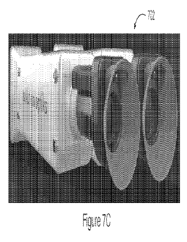
[0092] Figures 7A, 7B and 7C are perspective views of exemplary light field
refractors/phoropters, showing a casing thereof in cross-section (A and B) and
a unit
combining side-by-side two of the units (C) shown in 7A and 7B, in accordance
with one
embodiment;
[0093] Figure 8 is a process flow diagram of an exemplary
dynamic subjective vision
testing method, in accordance with one embodiment;
17
CA 03209939 2023- 8- 25
WO 2022/186894
PCT/US2021/070936
[0094] Figure 9 is a schematic diagram of an exemplary light
field image showing two
columns of optotypes at different dioptric power for the method of Figure 8,
in accordance
with one embodiment;
[0095] Figures 10A and 10B are process flow diagrams of
exemplary input constant
parameters and variables, respectively, for the ray-tracing rendering process
of Figure 11,
in accordance with one embodiment;
[0096] Figure 11 is a process flow diagram of an illustrative
ray-tracing rendering
process, in accordance with one embodiment;
[0097] Figure 12 is a process flow diagram illustrating a
process step of Figure 11, in
accordance with one embodiment;
[0098] Figure 13 is a process flow diagram illustrating certain
process steps of Figure
11, in accordance with one embodiment;
[0099] Figures 14A and 14B are schematic diagrams illustrating
certain process steps
of Figure 11, in accordance with one embodiment;
[00100] Figure 15 is a schematic diagram illustrating the process steps of
Figures 13 and
16, in accordance with one embodiment;
[00101] Figure 16 is a process flow diagram illustrating certain process steps
of Figure
11, in accordance with one embodiment;
[00102] Figures 17A to 17D are schematic diagrams illustrating certain process
steps of
Figures 13 and 16, in accordance with one embodiment;
[00103] Figures 18 and 19 are schematic diagrams illustrating ray-tracing in
the context
of non-parallel planes, in accordance with one embodiment;
[00104] Figures 20A and 20B are process flow diagrams of certain process steps
of
Figure 11 for rendering a light field originating from multiple distinct
virtual image planes,
in accordance with one embodiment;
18
CA 03209939 2023- 8- 25
WO 2022/186894
PCT/ITS2021/070936
[00105] Figures 21A and 21B are process flow diagrams of certain process steps
of
Figures 20A and 20B for rendering a light field originating from multiple
distinct virtual
image planes, in accordance with one embodiment;
[00106] Figures 22A to 22D are schematic diagrams illustrating certain process
steps of
Figures 21A and 21B, in accordance with one embodiment;
[00107] Figures 23A and 23B are process flow diagrams of certain process steps
of
Figure 11 for rendering a light field originating from multiple distinct focal
planes, in
accordance with one embodiment;
[00108] Figures 24A and 24B are schematic diagrams illustrating an example of
a
subjective visual acuity test using the ray-tracing rendering process of
Figures 23A or
Figure 23B, in accordance with one embodiment;
[00109] Figures 25A, 25B, 25C and 25D are, respectively, a schematic diagram
of an
exemplary refractor device, a schematic diagram illustrating certain variables
for a
binocular implementation of the refractor device, a photograph of a light
field image
5 produced by the exemplary refractor device, and a plot illustrating the
change in resolution
of a light field image as a function of the cylindrical dioptric power
correction, in
accordance with one embodiment;
[00110] Figures 26A and 26B are plots illustrating the change in binocular
field of view
(FoV) in arcminutes with respect to the scene distance from the eye in mm, in
accordance
with different embodiments;
[00111] Figures 27A and 27B are schematic diagrams of an exemplary binocular
refractor device comprising mirror assemblies configured to redirect light
field images so
that they exit the refractor device in accordance with the user's
interpupillary distance, in
accordance with one embodiment;
[00112] Figures 28A, 28B and 28C are schematic diagrams illustrating an
exemplary
refractor device using, in addition to the mirror assembly of Figure 27A, a
telescope
assembly, in accordance with three different embodiments;
19
CA 03209939 2023- 8- 25
WO 2022/186894
PCT/ITS2021/070936
[00113] Figure 29 is a schematic diagram illustrating view zone width and
spacing, in
accordance with one embodiment;
[00114] Figures 30A and 30B are photographs of two light field images, one
showing
footprints of circular view zone (software pupil) overlapping with one another
(30A) and
the other generated by the same refractor device using a software pupil
reshaping function
to remove the overlap (30B), in accordance with one embodiment;
[00115] Figures 31A and 31B are schematic diagrams illustrating a software
pupil
reshaping function, in accordance with one embodiment;
[00116] Figures 32A to 32C are schematic diagrams illustrating the rendering
of
multiple light field images simultaneously using spatial interlacing (32A),
temporal
interlacing (32B) or a combination thereof (32C);
[00117] Figure 33 is a process flow diagram of a vision testing method using a
binocular
light field refractor, in accordance with one embodiment; and
[00118] Figures 34A and 34B are process flow diagrams illustrating additional
steps
used to enable stereoscopic vision for method 1100, either when ray-tracing on
a virtual
image plane (34A) or on an eye focal plane (34B), in accordance with
respective
embodiments; and
[00119] Elements in the several figures are illustrated for simplicity and
clarity and have
not necessarily been drawn to scale. For example, the dimensions of some of
the elements
in the figures may be emphasized relative to other elements for facilitating
understanding
of the various presently disclosed embodiments. Also, common, but well-
understood
elements that are useful or necessary in commercially feasible embodiments are
often not
depicted in order to facilitate a less obstructed view of these various
embodiments of the
present disclosure.
DETAILED DESCRIPTION
[00120] Various implementations and aspects of the specification will be
described with
reference to details discussed below. The following description and drawings
are
CA 03209939 2023- 8- 25
WO 2022/186894
PCT/ITS2021/070936
illustrative of the specification and are not to be construed as limiting the
specification.
Numerous specific details are described to provide a thorough understanding of
various
implementations of the present specification. However, in certain instances,
well-known or
conventional details are not described in order to provide a concise
discussion of
implementations of the present specification.
[00121] Various apparatuses and processes will be described below to provide
examples
of implementations of the system disclosed herein. No implementation described
below
limits any claimed implementation and any claimed implementations may cover
processes
or apparatuses that differ from those described below. The claimed
implementations are
not limited to apparatuses or processes having all of the features of any one
apparatus or
process described below or to features common to multiple or all of the
apparatuses or
processes described below. It is possible that an apparatus or process
described below is
not an implementation of any claimed subject matter.
[00122] Furthermore, numerous specific details are set forth in order to
provide a
thorough understanding of the implementations described herein. However, it
will be
understood by those skilled in the relevant arts that the implementations
described herein
may be practiced without these specific details. In other instances, well-
known methods,
procedures and components have not been described in detail so as not to
obscure the
implementations described herein.
[00123] In this specification, elements may be described as "configured to"
perform one
or more functions or "configured for" such functions. In general, an element
that is
configured to perform or configured for performing a function is enabled to
perform the
function, or is suitable for performing the function, or is adapted to perform
the function,
or is operable to perform the function, or is otherwise capable of performing
the function.
[00124] It is understood that for the purpose of this specification, language
of "at least
one of X, Y, and 7" and "one or more of X, Y and 7" may he construed as X
only, Y only,
Z only, or any combination of two or more items X, Y, and Z (e.g., XYZ, XY,
YZ, ZZ, and
the like). Similar logic may be applied for two or more items in any
occurrence of "at least
one ..." and "one or more..." language.
21
CA 03209939 2023- 8- 25
WO 2022/186894
PCT/ITS2021/070936
[00125] Unless defined otherwise, all technical and scientific terms used
herein have the
same meaning as commonly understood by one of ordinary skill in the art to
which this
invention belongs.
[001261 Throughout the specification and claims, the following terms take the
meanings
explicitly associated herein, unless the context clearly dictates otherwise.
The phrase "in
one of the embodiments" or "in at least one of the various embodiments" as
used herein
does not necessarily refer to the same embodiment, though it may. Furthermore,
the phrase
"in another embodiment" or "in some embodiments" as used herein does not
necessarily
refer to a different embodiment, although it may. Thus, as described below.
various
embodiments may be readily combined, without departing from the scope or
spirit of the
innovations disclosed herein.
[00127] In addition, as used herein, the term "or- is an inclusive "or"
operator, and is
equivalent to the term "and/or," unless the context clearly dictates
otherwise. The term
"based on- is not exclusive and allows for being based on additional factors
not described,
unless the context clearly dictates otherwise. In addition, throughout the
specification, the
meaning of "a," "an," and "the" include plural references. The meaning of "in"
includes
"in" and "on."
[00128] As used in the specification and claims, the singular forms "a", "an"
and "the"
include plural references unless the context clearly dictates otherwise.
[001291 The term -comprising" as used herein will be understood to mean that
the list
following is non-exhaustive and may or may not include any other additional
suitable
items, for example one or more further feature(s), component(s) and/or
element(s) as
appropriate.
[00130] The systems and methods described herein provide, in accordance with
different embodiments, different examples of light field vision-based testing
systems and
methods for assessing the presence of one or more vision-related physiological
conditions,
such as a light field refractor and/or refractor, or vision-based cognitive
impairment
22
CA 03209939 2023- 8- 25
WO 2022/186894
PCT/ITS2021/070936
detection device or system, adjusted pixel rendering methods therefor, and
online or
telepresence vision-based testing systems and methods using same.
[00131] These vision-related physiological conditions, as the name implies,
may include
any physiological condition which affects, directly or indirectly, a patient's
visual system.
For example, this may include reduced or impacted visual acuity itself, but
also other
conditions such as cognitive impairment as a result of a concussion or similar
neurological
trauma that may impact a user's vision, visual acuity, responsivity, etc.
[00132] In addition, the systems and methods described herein also provide, in
some
embodiments, for remotely administering via a network connection, at least in
part, a
vision-based examination by a remotely located specialist, for example an
ophthalmologist
or eye doctor in the case of a vision examination or a physician or brain
specialist in the
case of a cognitive impairment examination. Such telepresence may allow for
enhanced
accuracy in the implementation of a particular test, greater patient comfort
during and trust
in results achieved from such tests, greater geographical reach of such tests
for
implementation in the field (e.g. within a competitive sport context,
dangerous work sites,
etc.) or in remote locations where expertise on the ground may be limited or
inaccessible,
or other such advantages.
[00133] For example, a subjective vision (e.g. blur) testing tool can rely on
the herein-
described solutions to simultaneously depict distinct optotypes corresponding
to respective
optical resolving or corrective powers in providing a subjective basis for
optical testing
comparisons, while concurrently or intermittently rendering testing guidance
or support
from within a same device, such as by means of an integrated livestream or pre-
recorded
guidance video, instructions or the like. For example, the devices, displays
and methods
described herein may allow a user's perception of one or more input images (or
input image
portions), where each image or image portion is virtually located at a
distinct image
plane/depth location, to be adjusted or altered using the light field display.
These may be
used, as described below, to provide vision correction for a user viewing such
digital
displays, but the same light field displays and rendering technology, as
detailed below and
according to different embodiments, may also be used or be implemented in a
refractor or
23
CA 03209939 2023- 8- 25
WO 2022/186894
PCT/ITS2021/070936
phoropter-like device to test, screen, diagnose and/or deduce a patient's
reduced visual
acuity.
[00134] In accordance with some embodiments. different vision testing devices
and
systems as described herein may be contemplated so to replace or complement
traditional
vision testing devices such as refractors and/or phoropters, in which
traditional devices
different optotypes are shown to a user in sequence via changing and/or
compounding
optical elements (lenses, prisms, etc.) so to identify an optical combination
that best
improves the user's perception of these displayed optotypes. As will be
described in greater
detail below, embodiments as described herein introduce light field display
technologies
and image rendering techniques, alone or in combination with complementary
optical
elements such as refractive lens, prisms, etc., to provide, amongst other
benefits, for greater
vision testing versatility, compactness, portability, range, precision, and/or
other benefits
as will be readily appreciated by the skilled artisan. Accordingly, while the
terms light field
refractor or phoropter will be used interchangeably herein to reference the
implementation
of different embodiments of a more generally defined light field vision
testing device and
system, the person of ordinary skill in the art will appreciate the
versatility of the herein
described implementation of light field rendering techniques, and ray tracing
approaches
detailed herein with respect to some embodiments, in the provision of
effective light field
vision testing devices and systems in general.
[00135] As noted above, some of the herein described embodiments provide for
digital
display devices, or devices encompassing such displays, for use by users
having reduced
visual acuity, whereby images ultimately rendered by such devices can be
dynamically
processed to accommodate the user's reduced visual acuity so that they may
consume
rendered images without the use of corrective eyewear, as would otherwise be
required.
Accordingly, such embodiments can be dynamically controlled to progressively
adjust a
user's perception of rendered images or image portions (e.g. optotype within
the context of
a blur test for example) until an optimized correction is applied that
optimizes the user's
perception. Perception adjustment parameters used to achieve this optimized
perception
can then be translated into a proposed vision correction prescription to be
applied to
corrective eyewear. Conversely, a user's vision correction eyewear
prescription can be
24
CA 03209939 2023- 8- 25
WO 2022/186894
PCT/ITS2021/070936
used as input to dictate selection of applied vision correction parameters and
related image
perception adjustment, to validate or possibly further fine tune the user's
prescription, for
example, and progressively adjusting such correction parameters to test for
the possibility
of a further improvement. As noted above, embodiments are not to be limited as
such as
the notions and solutions described herein may also be applied to other
technologies in
which a user's perception of an input image to be displayed can be altered or
adjusted via
the light field display. However, for the sake of illustration, a number of
the herein
described embodiments will be described as allowing for implementation of
digitally
adaptive vision tests such that individuals with such reduced visual acuity
can be exposed
to distinct perceptively adjusted versions of an input image(s) (e.g.
optotypes) to
subjectively ascertain a potentially required or preferred vision correction.
[00136] Moreover, different vision or visual system testing tools may also
rely on the
herein described solutions to provide a fast and reliable response when a head
injury
happens. For example, after mild traumatic head injury (TBI) or concussion,
common
visual disorders that may ensue include convergence insufficiency (CI),
accommodative
insufficiency (Al), and mild saccadic dysfunction (SD). Since a mild
concussion is
frequently associated with abnormalities of saccades, pursuit eye movements,
convergence, accommodation, and the vestibular-ocular reflex, testing or
evaluating the
vision system or eyes of an individual suspected of being cognitively impaired
may be used
to detect abnormalities in some of these aspects. For example, such tools may
be highly
beneficial, in some embodiments or applications, for a quick evaluation,
assessment or
screening (e.g. in a clinical environment, in the field and/or through other
direct/remote
configurations), especially when it may differentiate between mild and no
concussion.
Most people with visual complaints after a concussion have 20/20 distance
visual acuity so
more specific testing of near acuity, convergence amplitudes, ocular motility,
and
peripheral vision can be done. The light field rendering and vision testing
tools described
below may be used to implement the required tests to evaluate some of the
signs and
symptoms of TBI. Furthermore, the telepresence features described herein in
accordance
with some embodiments may again enhance or promote greater adherence to
testing
protocols, and/or provide more reliable results and conclusions.
CA 03209939 2023- 8- 25
WO 2022/186894
PCT/ITS2021/070936
[00137] Generally, digital displays as considered herein will comprise a set
of image
rendering pixels and a corresponding set of light field shaping elements that
at least
partially govern a light field emanated thereby to produce a perceptively
adjusted version
of the input image, notably distinct perceptively adjusted portions of an
input image or
input scene, which may include distinct portions of a same image, a same
2.5D/3D scene,
or distinct images (portions) associated with different image depths, effects
and/or
locations and assembled into a combined visual input. For simplicity, the
following will
generally consider distinctly addressed portions or segments as distinct
portions of an input
image, whether that input image comprises a singular image having distinctly
characterized
portions, a digital assembly of distinctly characterized images, overlays,
backgrounds,
foregrounds or the like, or any other such digital image combinations.
[00138] In some examples, light field shaping elements may take the form of a
light
field shaping layer or like array of optical elements to he disposed relative
to the display
pixels in at least partially governing the emanated light field. As described
in further detail
below, such light field shaping layer elements may take the form of a
microlens and/or
pinhole array, or other like arrays of optical elements, or again take the
form of an
underlying light shaping layer, such as an underlying array of optical
gratings or like optical
elements operable to produce a directional pixelated output.
[00139] Within the context of a light field shaping layer, as described in
further detail
below in accordance with some embodiments, the light field shaping layer can
be disposed
at a pre-set distance from the pixelated display so to controllably shape or
influence a light
field emanating therefrom. For instance, each light field shaping layer can be
defined by
an array of optical elements centered over a corresponding subset of the
display's pixel
array to optically influence a light field emanating therefrom and thereby
govern a
projection thereof from the display medium toward the user, for instance,
providing some
control over how each pixel or pixel group will be viewed by the viewer's
eye(s). As will
be further detailed below, arrayed optical elements may include, but are not
limited to,
lenslets, microlenses or other such diffractive optical elements that together
form, for
example, a lenslet array; pinholes or like apertures or windows that together
form, for
example, a parallax or like barrier; concentrically patterned barriers, e.g.
cut outs and/or
26
CA 03209939 2023- 8- 25
WO 2022/186894
PCT/ITS2021/070936
windows, such as a to define a Fresnel zone plate or optical sieve, for
example, and that
together form a diffractive optical barrier (as described, for example. in
Applicant's co-
pending U.S. Application Serial No. 15/910.908, the entire contents of which
are hereby
incorporated herein by reference); and/or a combination thereof, such as for
example, a
lenslet array whose respective lenses or len slets are partially shadowed or
barriered around
a periphery thereof so to combine the refractive properties of the lenslet
with some of the
advantages provided by a pinhole barrier.
[00140] In operation, the display device will also generally invoke a hardware
processor
operable on image pixel (or subpixel) data for an image to be displayed to
output corrected
or adjusted image pixel data to be rendered as a function of a stored
characteristic of the
light field shaping elements and/or layer, e.g. layer distance from display
screen, distance
between optical elements (pitch), absolute relative location of each pixel or
subpixel to a
corresponding optical element, properties of the optical elements (size,
diffractive and/or
refractive properties, etc.), or other such properties, and a selected vision
correction or
adjustment parameter related to the user's reduced visual acuity or intended
viewing
experience. While light field display characteristics will generally remain
static for a given
implementation (i.e. a given shaping element and/or layer will be used and set
for each
device irrespective of the user), image processing can, in some embodiments,
be
dynamically adjusted as a function of the user's visual acuity or intended
application so to
actively adjust a distance of a virtual image plane, or perceived image on the
user's retinal
plane given a quantified user eye focus or like optical aberration(s), induced
upon rendering
the corrected/adjusted image pixel data via the static optical layer and/or
elements, for
example, or otherwise actively adjust image processing parameters as may be
considered,
for example. when implementing a viewer-adaptive pre-filtering algorithm or
like approach
(e.g. compressive light field optimization), so to at least in part govern an
image perceived
by the user's eye(s) given pixel or subpixel-specific light visible thereby
through the layer.
[00141] With reference to Figures lA and 1B, and in accordance with different
embodiments, an exemplary subjective vision testing device/system
(interchangeably
referred to as a corrective vision previewing device/system), generally
referred to using the
numeral 100, will now be described. At the heart of this system is a light
field vision testing
27
CA 03209939 2023- 8- 25
WO 2022/186894
PCT/ITS2021/070936
device such as a light field refractor or phoropter device 102. Generally,
light field refractor
102 is a device comprising, as mentioned above, a light field display 104 and
which is
operable to display or generate one or more images, including optotypes, to a
user or patient
having his/her vision acuity (e.g. refractive error) tested.
[00142] In some embodiments, as illustrated in Figure 1B, light field display
104
comprises a light field shaping layer (LFSL) 108 overlaid or placed in front
of a digital
pixel display 110 (i.e. LCD, LED, OLED, etc.). For the sake of illustration,
the following
embodiments will be described within the context of a LFSL 108 defined, at
least in part,
by a lenslet array comprising an array of microlenses (also interchangeably
referred to
herein as lenslets) that are each disposed at a distance from a corresponding
subset of image
rendering pixels in an underlying digital display. It will be appreciated that
while a light
field shaping layer may be manufactured and disposed as a digital screen
overlay, other
integrated concepts may also he considered, for example, where light field
shaping
elements are integrally formed or manufactured within a digital screen's
integral
components such as a textured or masked glass plate, beam-shaping light
sources (e.g.
directional light sources and/or backlit integrated optical grating array) or
like component.
[00143] Accordingly, each lenslet will predictively shape light emanating from
these
pixel subsets to at least partially govern light rays being projected toward
the user by the
display device. As noted above, other light field shaping layers may also be
considered
herein without departing from the general scope and nature of the present
disclosure,
whereby light field shaping will he understood hy the person of ordinary skill
in the art to
reference measures by which light, that would otherwise emanate
indiscriminately (i.e.
isotropically) from each pixel group, is deliberately controlled to define
predictable light
rays that can be traced between the user and the device's pixels through the
shaping layer.
[00144] For greater clarity, a light field is generally defined as a vector
function that
describes the amount of light flowing in every,- direction through every point
in space. In
other words, anything that produces or reflects light has an associated light
field. The
embodiments described herein produce light fields from an object that are not
"natural"
vector functions one would expect to observe from that object. This gives it
the ability to
28
CA 03209939 2023- 8- 25
WO 2022/186894
PCT/ITS2021/070936
emulate the -natural" light fields of objects that do not physically exist,
such as a virtual
display located far behind the light field display.
[00145] In one example, to apply this technology to vision correction,
consider first the
normal ability of the lens in an eye, as schematically illustrated in Figure
2A, where, for
normal vision, the image is to the right of the eye (C) and is projected
through the lens (B)
to the retina at the back of the eye (A). As comparatively shown in Figure 2B,
the poor lens
shape and inability to accommodate (F) in presbyopia causes the image to be
focused past
the retina (D) forming a blurry image on the retina (E). The dotted lines
outline the path of
a beam of light (G). Naturally, other optical aberrations present in the eye
will have
different impacts on image formation on the retina. To address these
aberrations, a light
field display 104, in accordance with some embodiments, projects the correct
sharp image
(H) on the retina for an eye with a crystalline lens which otherwise could not
accommodate
sufficiently to produce a sharp image. The other two light field pixels (I)
and (J) are drawn
lightly, but would otherwise fill out the rest of the image.
[00146] As will be appreciated by the skilled artisan, a light field as seen
in Figure 2C
cannot be produced with a 'normal' two-dimensional display because the pixels'
light field
emits light isotopically. Instead it is necessary to exercise tight control on
the angle and
origin of the light emitted, for example, using a microlens array or other
light field shaping
layer such as a parallax barrier, or combination thereof. Following with the
example of a
microlens array for LFSL 106, Figure 3A schematically illustrates a single
light field pixel
defined by a convex microlens 302 disposed at its focus from a corresponding
subset of
pixels in a digital pixel display 108 to produce a substantially collimated
beam of light
emitted by these pixels, whereby the direction of the beam is controlled by
the location of
the pixel(s) relative to the microlens. The single light field pixel produces
a beam similar
to that shown in Figure 2C where the outside rays are lighter and the majority
inside rays
are darker. The digital pixel display 108 emits light which hits the microlens
302 and it
results in a beam of substantially collimated light (A).
[00147] Accordingly, upon predictably aligning a particular microlens array
with a pixel
array, a designated "circle" of pixels will correspond with each microlens and
be
29
CA 03209939 2023- 8- 25
WO 2022/186894
PCT/US2021/070936
responsible for delivering light to the pupil through that lens. Figure 3B
schematically
illustrates an example of a light field display assembly in which a LFSL 106
sits above a
pixel display 108 to have pixels 304 emit light through the microlens array. A
ray-tracing
algorithm can thus be used to produce a pattern to be displayed on the pixel
array below
the microlens in order to create the desired virtual image that will
effectively correct for
the viewer's reduced visual acuity.
[00148] As will be detailed further below, the separation between the LFSL 106
and the
pixel array 108 as well as the pitch of the lenses can be selected as a
function of various
operating characteristics, such as the normal or average operating distance of
the display,
and/or normal or average operating ambient light levels.
[00149] In some embodiments, LFSL 106 may be a microlens array (MLA) defined
by
a hexagonal array of microlenses or lenslet disposed so to overlay a
corresponding square
pixel array of digital pixel display 108. In doing so, while each microlens
can be aligned
with a designated subset of pixels to produce light field pixels as described
above, the
hexagonal-to-square array mismatch can alleviate certain periodic optical
artifacts that may
otherwise be manifested given the periodic nature of the optical elements and
principles
being relied upon to produce the desired optical image corrections.
Conversely, a square
microlens array may be favoured when operating a digital display comprising a
hexagonal
pixel array.
[00150] In some embodiments, the MLA may further or alternatively be overlaid
or
disposed at an angle (rotation) relative to the underlying pixel array, which
can further or
alternatively alleviate period optical artifacts.
[00151] In yet some further or alternative embodiments, a pitch ratio between
the
microlens array and pixel array may be deliberately selected to further or
alternatively
alleviate periodic optical artifacts. For example, a perfectly matched pitch
ratio (i.e. an
exact integer number of display pixels per micrelens) is most likely to induce
periodic
optical artifacts, whereas a pitch ratio mismatch can help reduce such
occurrences.
CA 03209939 2023- 8- 25
WO 2022/186894
PCT/ITS2021/070936
[00152] Accordingly, in some embodiments, the pitch ratio will be selected to
define an
irrational number, or at least, an irregular ratio, so to minimize periodic
optical artifacts.
For instance, a structural periodicity can be defined so to reduce the number
of periodic
occurrences within the dimensions of the display screen at hand, e.g. ideally
selected so to
define a structural period that is greater than the size of the display screen
being used.
[00153] While this example is provided within the context of a microlens
array, similar
structural design considerations may be applied within the context of a
parallax barrier,
diffractive barrier or combination thereof. In some embodiments, light field
display 104
can render dynamic images at over 30 frames per second on the hardware in a
smartphone.
[00154]
Accordingly, a display device as described above and further exemplified
below, can be configured to render a corrected or adjusted image via the light
field shaping
layer that accommodates, tests or simulates for the user's visual acuity. By
adjusting the
image correction in accordance with the user's actual predefined, set or
selected visual
acuity level, different users and visual acuity may be accommodated using a
same device
configuration, whereas adjusting such parameters for a given user may allow
for testing for
or simulation of different corrective or visual adjustment solutions. For
example, by
adjusting corrective image pixel data to dynamically adjust a virtual image
distance
below/above the display as rendered via the light field shaping layer,
different visual acuity
levels may be accommodated, and that, for an image input as a whole, for
distinctly various
portions thereof, or again progressively across a particular input.
[00155] As noted in the examples below, in some embodiments, light field
rendering
may be adjusted to effectively generate a virtual image on a virtual image
plane that is set
at a designated distance from an input user pupil location, for example, so to
effectively
push back, or move forward, a perceived image, or portion thereof, relative to
the light field
refractor device 102. In yet other embodiments, light field rendering may
rather or
alternatively seek to map the input image on a retinal plane of the user,
taking into account
visual aberrations, so to adaptively adjust rendering of the input image on
the display
device to produce the mapped effect. Namely, where the unadjusted input image
would
otherwise typically come into focus in front of or behind the retinal plane
(and/or he subject
31
CA 03209939 2023- 8- 25
WO 2022/186894
PCT/ITS2021/070936
to other optical aberrations), this approach allows to map the intended image
on the retinal
plane and work therefrom to address designated optical aberrations
accordingly. Using this
approach, the device may further computationally interpret and compute virtual
image
distances tending toward infinity, for example, for extreme cases of
presbyopia. This
approach may also more readily allow, as will be appreciated by the below
description, for
adaptability to other visual aberrations that may not be as readily modeled
using a virtual
image and image plane implementation. In both of these examples, and like
embodiments,
the input image is digitally mapped to an adjusted image plane (e.g. virtual
image plane or
retinal plane) designated to provide the user with a designated image
perception adjustment
that at least partially addresses designated visual aberrations. Naturally,
while visual
aberrations may be addressed using these approaches, other visual effects may
also be
implemented using similar techniques.
[001156]
As an example of the effectiveness of the light field display in
generating a
diopter displacement (e.g. simulate the effect of looking through an optical
component (i.e.
a lens) of a given diopter strength or power) is shown in Figure 5, where a
plot is shown of
the angular resolution (in arcminutes) of an exemplary light field display
comprising a 1500
ppi digital pixel display, as a function of the dioptric power of the light
field image (in
diopters). From this plot, it is clear that, in this particular example, the
light field display is
able to generate displacements (line 502) in diopters that have higher
resolution
corresponding to 20/20 vision (line 504) or better (e.g. 20/15 ¨ line 506) and
close to (20/10
¨ line 508)), here within a dioptric power range of 2 to 2.5 diopters.
[00157] Thus, in the context of a refractor 102, light field display 104 may,
according
to different embodiments, be used to replace, at least in part, traditional
optical
components.
[00158] In some embodiments, the light field display can display a virtual
image at
optical infinity, meaning that any level of accommodation-based presbyopia
(e.g. first
order) can be corrected for. In some further embodiments, the light field
display can both
push the image back or forward, thus allowing for selective image corrections
for both
hyperopia (far-sightedness) and myopia (nearsightedness). In yet further
embodiments as
32
CA 03209939 2023- 8- 25
WO 2022/186894
PCT/ITS2021/070936
described below, variable displacements and/or accommodations may be applied
as a
function of non-uniform visual aberrations, or again to provide perceptive
previewing or
simulation of non-uniform or otherwise variable corrective powers/measures
across a
particular input or field of view.
[00159] However, the light field rendering system introduced above and the ray-
tracing
methods described below may also be used with other devices which may
similarly
comprise a light field display. For example, this may include a smartphone,
tablets, e-
readers, watches, televisions, GPS devices, laptops, desktop computer
monitors,
televisions, smart televisions, handheld video game consoles and controllers,
vehicular
dashboard and/or entertainment displays, and the like, without limitation.
[00160] Accordingly, any of the light field processing or ray-tracing methods
described
below, any modification thereto also discussed below, and related light field
display
solutions, can be equally applied to image perception adjustment solutions for
visual media
consumption, as they can for subjective vision testing solutions, or other
technologically
related fields of endeavour. As alluded to above, the light field display and
rendering/ray-
tracing methods discussed above may all be used to implement, according to
various
embodiments, a subjective vision testing device or system such as a phoropter
or refractor.
Indeed, a light field display may replace, at least in part, the various
refractive optical
components usually present in such a device. Thus, the vision correction light
field ray
tracing methods discussed below may equally be applied to render optotypes at
different
dioptric power or refractive correction by generating vision correction for
hyperopia (far-
sightedness) and myopia (nearsightedness), as was described above in the
general case of
a vision correction display. Light field systems and methods described herein,
according to
some embodiments, may be applied to create the same capabilities as a
traditional
instrument and to open a spectrum of new features, all while improving upon
many other
operating aspects of the device. For example, the digital nature of the light
field display
enables continuous changes in dioptric power compared to the discrete change
caused by
switching or changing a lens or similar; displaying two or more different
dioptric
corrections seamlessly at the same time; and, in some embodiments, the
possibility of
33
CA 03209939 2023- 8- 25
WO 2022/186894
PCT/ITS2021/070936
measuring higher-order aberrations and/or to simulate them for different
purposes such as,
deciding for free-form lenses, cataract surgery operation protocols, IOL
choice, etc.
[00161] Going back to Figure 1A, as producing a light field with angular
resolution
sufficient for accommodation correction over the full viewing 'zone' of a
display would
generally require an astronomically high pixel density, instead, a correct
light field can be
produced, in some embodiments, only at or around the location of the user's
pupil(s). To
do so, where a location or position of the user's eye is not otherwise rigidly
constrained
(e.g. within the context of a subject eye testing device or the like) the
light field display can
be paired with pupil tracking technology, as will be discussed below, to track
a location of
the user's eyes/pupils relative to the display. The display can then
compensate for the user's
eye location and produce the correct virtual image, for example, in real-time.
Thus, in
some embodiments, light field refractor 102 may include, integrated therein or
interfacing
therewith, a pupil/eye tracking system 110 to improve or enhance corrective
image
rendering by tracking a location of the user's eye(s)/pupil(s) (e.g. both or
one, e.g.
dominant, eye(s)) and adjusting light field corrections accordingly one or
more eye/pupil
tracking light sources, such as one or more infrared (IR) or near-IR (NIR)
light source(s)
to accommodate operation in limited ambient light conditions, leverage retinal
retro-
reflections, invoke corneal reflection, and/or other such considerations. For
instance,
different IR/NIR pupil tracking techniques may employ one or more (e.g.
arrayed) directed
or broad illumination light sources to stimulate retinal retro-reflection
and/or corneal
reflection in identifying a tracking a pupil location. Other techniques may
employ ambient
or IR/NIR light-based machine vision and facial recognition techniques to
otherwise locate
and track the user's eye(s)/pupil(s). To do so, one or more corresponding
(e.g. visible,
IR/NIR) cameras may be deployed to capture eye/pupil tracking signals that can
be
processed, using various image/sensor data processing techniques, to map a 3D
location of
the user's eye(s)/pupil(s). As mentioned above, in some embodiments, such
eye/pupil
tracking hardware/software may be integral to device 102, for instance,
operating in concert
with integrated components such as one or more front facing camera(s), onboard
IR/NIR
light source(s) (not shown) and the like. In other user environments, such as
in a vehicular
environment, eye/pupil tracking hardware may be further distributed within the
34
CA 03209939 2023- 8- 25
WO 2022/186894
PCT/ITS2021/070936
environment, such as dash, console, ceiling, windshield, mirror or similarly-
mounted
camera(s), light sources, etc.
[00162] In one embodiment and as illustrated in Figure 4A, light field
refractor 102 may
be configured with light field display 104 located relatively far away (e.g.
one or more
meters) from the user's eye currently being diagnosed. Note that the pointed
line in Figures
4A to 4C is used to schematically illustrate the direction of the light rays
emitted by light
field display 104. Also illustrated is eye-tracker 110, which may be provided
as a physically
separate element, for example, installed in at a given location in a room or
similar. In some
embodiments, the noted eye/pupil tracker 110 may include the projection of IR
markers/patterns to help align the patient's eye with the light field display.
In some
embodiments, a tolerance window (e.g. "eye box") may be considered to limit
the need to
refresh the ray-tracing iteration. An exemplary value of the size of the eye
box, in some
embodiments, is around 6 mm, though smaller (e.g. 4mm) or larger eye boxes may
alternatively be set to impact image quality, stability or like operational
parameters.
[00163] Going back to Figure 1A, light field refractor 102 may also comprise,
according
to different embodiments and as will be further discussed below, one or more
refractive
optical components 112, a processing unit 114, a data storage unit or internal
memory 116,
one or more cameras 118, a power source 120, a network interface 122 for
communicating
via network to a remote database or server 124.
[00164] In some embodiments, power source 120 may comprise, for example, a
rechargeable Li-ion battery or similar. In some embodiments, it may comprise
an additional
external power source, such as, for example, a CSB-C external power supply. It
may also
comprise a visual indicator (screen or display) for communicating the device's
power
status, for example whether the device is on/off or recharging.
[00165] In some embodiments, internal memory 116 may be any form of electronic
storage, including a disk drive, optical drive, read-only memory, random-
access memory,
or flash memory, to name a few examples. In some embodiments, a library of
chart patterns
(Snellen charts, prescribed optotypes, forms, patterns, or other) may be
located in internal
memory 116 and/or retrievable from remote server 124 via network interface
122.
CA 03209939 2023- 8- 25
WO 2022/186894
PCT/ITS2021/070936
[00166] In some embodiments, one or more optical components 112 may be used in
combination with the light field display 104, for example to shorten the size
of refractor
102 and still offer an acceptable range in dioptric power. The general
principle is
schematically illustrated in the plots of Figures 6A to 6D. In these schematic
plots, the
image quality (e.g. inverse of the angular resolution, higher is better) at
which optotypes
are small enough to be useful for vision testing in this plot is above
horizontal line 602
which represents typical 20/20 vision. Figure 6A shows the plot for the light
field display
only, where we see the characteristic two peaks corresponding to the smallest
resolvable
point, one of which was plotted in Figure 5 (here inverted and shown as a peak
instead of
a basin), and where each region above the line may cover a few diopters of
dioptric power,
according to some embodiments. While the dioptric range may, in some
embodiments, be
more limited than needed when relying only on the light field display, it is
possible to shift
this interval by adding one or more refractive optical components. This is
shown in Figure
6B where the regions above the line 602 is shifted to the left (negative
diopters) by adding
a single lens in the optical path.
[00167] Thus, by using a multiplicity of refractive optical components 112 or
by
alternating sequentially between different refractive components 112 of
increasing or
decreasing dioptric power, it is possible to shift the center of the light
field diopter range
to any required value, as shown in Figure 6C, and thus the image quality may
be kept above
line 602 for any required dioptric power as shown in Figure 6D. In some
embodiments, a
range of 30 diopters from +10 to -20 may be covered for example. In the case
of one or
more reels of lenses, the lens may be switched for a given larger dioptric
power increment,
and the light field display would be used to provide a finer continuous change
to accurately
pin-point the required total dioptric power required to compensate for the
patient's reduced
visual acuity. This would still result in light field refractor 102 having a
reduced number
of refractive optical components compared to the number of components needed
in a
traditional refractor, while drastically enhancing the overall fine-tuning
ability of the
device.
[00168] One example, according to one embodiment, of such a light field
refractor 102
is schematically illustrated in Figure 4B, wherein the light field display 104
(herein shown
36
CA 03209939 2023- 8- 25
WO 2022/186894
PCT/ITS2021/070936
comprising LFSL 106 and digital pixel display 108) is combined with a
multiplicity of
refractive components 112 (herein illustrated as a reel of lenses as an
example only). By
changing the refractive component used in combination with light field display
104, a
larger dioptric range may be covered. This may also provide means to reduce
the dimension
of device 102 as mentioned above, making it more portable, so that all its
internal
components may be encompassed into a shell, housing or casing 402. In some
embodiments, light field refractor 102 may thus comprise a durable ABS housing
that may
be shock and harsh-environment resistant. In some embodiments, light field
refractor 102
may also comprise a telescopic feel for fixed or portable usage; optional
mounting brackets,
and/or a carrying case (not shown). In some embodiments, all components may be
internally protected and sealed from the elements.
[00169] In some embodiments, casing 402 may further comprise a head-rest or
similar
(not shown) to keep the user's head still and substantially in the same
location, thus, in
such examples, foregoing the general utility of a pupil tracker or similar
techniques by
substantially fixing a pupil location relative to this headrest.
[00170] In some embodiments, it may also be possible to further reduce the
size of
device 102 by adding, for example, a mirror or any device which may increase
the optical
path. This is illustrated in Figure 4C where the length of the device was
reduced by adding
a mirror 404. This is shown schematically by the pointed arrow which
illustrates the light
being emitted from pixel display 108 travelling through LFSL 106 before being
reflected
hack hy mirror through refractive components 112 and ultimately hitting the
eye.
[00171] The skilled technician will understand that different examples of
refractive
components 112 may be include, without limitation, one or more lenses,
sometimes
arranged in order of increasing dioptric power in one or more reels of lenses
similar to what
is typically found in traditional refractors/phoropters; an electrically
controlled fluid lens;
active Fresnel lens: and/or Spatial Light Modulators (SLM). In some
embodiments,
additional motors and/or actuators (not shown) may be used to operate
refractive
components 112. The motors/actuators may be communicatively linked to
processing unit
37
CA 03209939 2023- 8- 25
WO 2022/186894
PCT/ITS2021/070936
114 and power source 120, and operate seamlessly with light field display 102
to provide
the required dioptric power.
[00172] For example, Figures 7A and 7B show a perspective view of an exemplary
light
field phoropter 102 similar to the one schematically shown in Figure 3B, but
wherein the
refractive component 112 is an electrically tunable liquid lens. Thus, in this
particular
embodiment, no mechanical or moving component are used, which may result in
the device
being more robust. In some embodiments, the electrically tunable lens may have
a range
of 13 diopters.
[00173] In one illustrative embodiment, a 1000 dpi display is used with a MLA
having
a 65 mm focal distance and 1000 um pitch with the user's eye located at a
distance of about
26 cm. A similar embodiment uses the same MLA and user distance with a 3000
dpi
display.
[00174] Other displays having resolutions including 750 dpi, 1000 dpi, 1500
dpi and
3000 dpi were also tested or used, as were MLAs with a focal distance and
pitch of 65 mm
and 1000 pm, 43 mm and 525 pm, 65 mm and 590 m, 60 mm and 425 pm, 30 mm and
220 um, and 60 mm and 425 um, respectively, and user distances of 26 cm, 45 cm
or 65
cm.
[00175] Going back to Figure 1A, in some embodiments, eye-tracker 110 may
further
comprise a digital camera, in which case it may be used to further acquire
images of the
user's eye to provide further diagnostics, such as pupillary reflexes and
responses during
testing for example. In other embodiments, one or more additional cameras 118
may be
used to acquire these images instead. In some embodiments, light field
refractor 102 may
comprise built-in stereoscopic tracking cameras.
[00176] In some embodiments, feedback and/or control of the vision test being
administered by system 100 may be given via a control interface 126. In some
embodiments, the control interface 126 may comprise a dedicated handheld
controller-like
device 128. This controller 128 may be connected via a cable or wirelessly,
and may be
used by the patient directly and/or by an operator like an eye professional.
In some
38
CA 03209939 2023- 8- 25
WO 2022/186894
PCT/ITS2021/070936
embodiments, both the patient and operator may have their own dedicated
controller 128.
In some embodiments, the controller may comprise digital buttons, analog
thumbstick,
dials, touch screens, and/or triggers.
[00177] In some embodiments, control interface 126 may comprise a digital
screen or
touch screen, either on refractor 102 itself or part of an external module
(not shown). In
other embodiments, control interface 126 may let on or more external remote
devices (i.e.
computer, laptop, tablet, smartphone, remote, etc.) control light field
refractor 102 via
network interface 122. For example, remote digital device 130 may be connected
to light
field refractor 102 via a cable (e.g. USB cable, etc.) or wirelessly (e.g. via
Wi-Fi, Bluetooth
or similar) and interface with light field refractor 102 via a dedicated
application, software
or website (not shown). Such a dedicated application may comprise a graphical
user
interface (GUI), and may also be communicatively linked to remote database
124.
[00178] In some embodiments, the user or patient may give feedback verbally
and the
operator may control the vision test as a function of that verbal feedback. In
some
embodiments, refractor 102 may comprise a microphone (not shown) to record the
patient's
verbal communications, either to communicate them to a remote operator via
network
interface 122 or to directly interact with the device (e.g. via speech
recognition or similar).
[00179] Going back to Figure 1A, processing unit 114 may be communicatively
connected to data storage 116, eye tracker 110, light field display 104 and
refractive
components 112. Processing unit 114 may be responsible for rendering one or
more images
or optotypes via light field display 104 and, in some embodiments, jointly
control refractive
components 112 to achieve a required total change in dioptric power. It may
also be
operable to send and receive data to internal memory 116 or to/from remote
database 124
via network interface 122.
[00180] In some embodiments, diagnostic data may be automatically
transmitted/communicated to remote database 124 or remote digital device 130
via network
interface 122 through the use of a wired or wireless network connection. The
skilled artisan
will understand that different means of connecting electronic devices may be
considered
herein, such as, but not limited to, Wi-Fi, Bluetooth, NFC, Cellular, 2G, 3G,
4G, 5G or
39
CA 03209939 2023- 8- 25
WO 2022/186894
PCT/ITS2021/070936
similar. In some embodiments, the connection may be made via a connector cable
(e.g.
USB including microUSB, USB-C, Lightning connector, etc.). In some
embodiments,
remote digital device 130 may be located in a different room, building or
city.
[00181] In some embodiments, two light field refractors 102 may be combined
side-by-
side to independently measure the visual acuity of both left and right eye at
the same time.
An example is shown in Figure 7C, where two units corresponding to the
embodiment of
Figures 7A or 7B (used as an example only) are placed side-by-side or fused
into a single
device 702. Thus, such a binocular light field refractor device 702 would
comprise, in some
embodiments, every element described above with respect to monocular refractor
102 (e.g.
in Figure 1A) but further includes two sets of light field displays 104 and
refractive
components 112 instead of one (one for each eye). In some embodiments, instead
of having
a distinct light field display 104 for each eye, as shown in Figure 7C, a
single light field
display operable to project light field images to both eyes simultaneously may
be used as
well. In some embodiments, it may also comprise two eye trackers 110, again
one for each
eye, or it may use a single eye tracker 110 to track both eyes simultaneously.
Below, it will
be understood that any embodiment of refractor 102 or improvements thereto,
including
the addition of optical components, described above or below may equally apply
as well to
each left and right portions of refractor 702, without restriction. In some
embodiments,
refractor 702 may be used to do monocular vision testing, just like refractor
102, but it may
also be used to project a same image to both eyes simultaneously, as will be
discussed
further below.
[00182] In some embodiments, a dedicated application, software or website may
provide integration with third party patient data software. In some
embodiments, software
required to operate and installed on refractor 102 may be updated on-the-fly
via a network
connection and/or be integrated with the patient's smartphone app for updates
and
reminders.
[00183] In some embodiments, the dedicated application, software or website
may
further provide a remote, real-time collaboration platform between an eye
professional and
CA 03209939 2023- 8- 25
WO 2022/186894
PCT/ITS2021/070936
user/patient, and/or between different eye professionals. This may include
interaction
between different participants via video chat, audio chat, text messages, etc.
[00184] In some embodiments, light field refractor 102 may be self-operated or
operated
by an optometrist, ophthalmologist or other certified eye-care professional.
For example,
in some embodiments, a user/patient may use refractor 102 in the comfort of
his/her own
home, in a store or a remote location.
[00185] With reference to Figure 8 and in accordance with one exemplary
embodiment,
a dynamic subjective vision testing method using vision testing system 100,
generally
referred to using the numeral 800, will now be described. As mentioned above,
the use of
a light field display enables refractor 102 to provide more dynamic and/or
more modular
vision tests than what is generally possible with traditional
refractors/phoropters.
Generally, method 800 seeks to diagnose a patient's reduced visual acuity and
produce
therefrom, in some embodiments, an eye prescription or similar.
[00186] In some embodiments, eye prescription information may include, for
each eye,
one or more of: distant spherical, cylindrical and/or axis values, and/or a
near (spherical)
addition value.
[00187] In some embodiments, the eye prescription information may also include
the
date of the eye exam and the name of the eye professional that performed the
eye exam. In
some embodiments, the eye prescription information may also comprise a set of
vision
correction parameter(s), as will be further discussed below, for operating any
vision
correction light field displays using the systems and methods described below.
In some
embodiments, the eye prescription may be tied to a patient profile or similar,
which may
contain additional patient information such as a name, address or similar. The
patient
profile may also contain additional medical information about the user. All
information or
data (i.e. set of vision correction parameter(s), user profile data, etc.) may
be kept on
external database 124. Similarly, in some embodiments, the user's current
vision correction
parameter(s) may be actively stored and accessed from external database 124
operated
within the context of a server-based vision correction subscription system or
the like, and/or
41
CA 03209939 2023- 8- 25
WO 2022/186894
PCT/ITS2021/070936
unlocked for local access via the client application post user authentication
with the server-
based system.
[00188] Refractor 102 being, in some embodiments, portable, a large range of
environments may be chosen to deliver the vision test (home, eye
practitioner's office,
etc.). At the start, the patient's eye may be placed at the required location.
This may be
done by placing his/her head on a headrest or by placing the objective (i.e.
eyepiece) on
the eye to be diagnosed. As mentioned above, the vision test may be self-
administered or
partially self-administered by the patient. For example, the operator (e.g.
eye professional
or other) may have control over the type of test being delivered, and/or be
the person who
generates or helps generate therefrom an eye prescription, while the patient
may enter
inputs dynamically during the test (e.g. by choosing or selecting an optotype,
etc.).
[00189] As will be discussed below, light field rendering methods described
herein
generally requires an accurate location of the patient's pupil center. Thus,
at step 802, such
a location is acquired. In some embodiments, such a pupil location may be
acquired via
eye tracker 110, either once, at intervals, or continuously. In other
embodiments, the
location may be derived from the device or system's dimension. For example, in
some
embodiments, the use a head-rest and/or an eye-piece or similar provides an
indirect means
of deriving the pupil location. In some embodiments, refractor 102 may be self-
calibrating
and not require any additional external configuration or manipulation from the
patient or
the practitioner before being operable to start a vision test.
[00190] At step 804, one or more optotypes is/are displayed to the patient, at
one or
more dioptric power (e.g. in sequence, side-by-side, or in a grid
pattern/layout). The use of
light field display 104 offers multiple possibilities regarding how the
images/optotypes are
presented, and at which dioptric power each may be rendered. The optotypes may
be
presented sequentially at different dioptric power, via one or more dioptric
power
increments. In some embodiments, the patient and/or operator may control the
speed and
size of the dioptric power increments.
[00191] In some embodiments, optotypes may also be presented, at least in
part,
simultaneously on the same image but rendered at a different dioptric power.
For example,
42
CA 03209939 2023- 8- 25
WO 2022/186894
PCT/ITS2021/070936
Figure 9 shows an example of how different optotypes may be displayed to the
patient but
rendered with different dioptric powers simultaneously. These may be arranged
in columns
or in a table or similar. In Figure 9, we see two columns of three optotypes
(K, S. V),
varying in size, as they are perceived by a patient, each column being
rendered at different
degrees of refractive correction (e.g. dioptric power). In this specific
example, the
optotypes on the right are being perceived as blurrier than the optotypes on
the left.
[00192] Thus, at step 806, the patient would communicate/verbalize this
information to
the operator or input/select via, for example, control interface 126 the left
column as the
one being clearer. Thus, in some embodiments, method 800 may be configured to
implement dynamic testing functions that dynamically adjust one or more
displayed
optotype' s dioptric power in real-time in response to a designated input,
herein shown by
the arrow going back from step 808 to step 804 in the case where at step 808,
the user or
patient communicates that the perceived optotypes are still blurry or similar.
In the case of
sequentially presented optotypes, the patient may indicate when the optotypes
shown are
clearer. In some embodiments, the patient may control the sequence of
optotypes shown
(going back and forth as needed in dioptric power), and the speed and
increment at which
these are presented, until he/she identifies the clearest optotype. In some
embodiments, the
patient may indicate which optotype or which group of optotypes is the
clearest by moving
an indicator icon or similar within the displayed image.
[00193] In some embodiments, the optotypes may be presented via a video feed
or
similar.
[00194] In some embodiments, when using a reel of lenses or similar (for
refractive
components 112), discontinuous changes in dioptric power may be unavoidable.
For
example, the reel of lenses may be used to provide a larger increment in
dioptric power, as
discussed above. Thus, step 804 may in this case comprise first displaying
larger
increments of dioptric power by changing lens as needed, and when the clearest
or less
blurry optotypes are identified, fine-tuning with continuous or smaller
increments in
dioptric power using the light field display. In the case of optotypes
presented
simultaneously, the refractive components 112 may act on all optotypes at the
same time,
43
CA 03209939 2023- 8- 25
WO 2022/186894
PCT/ITS2021/070936
and the change in dioptric power between them may be controlled only by the
light display
104. In some embodiments, for example when using an electrically tunable fluid
lens or
similar, the change in dioptric power may be continuous.
[00195] In some embodiments, eye images may be recorded during steps 802 to
806 and
analyzed to provide further diagnostics. For example, eye images may be
compared to a
bank or database of proprietary eye exam images and analyzed, for example via
an artificial
intelligence (AI) or Machine-learning (ML) system or similar. This analysis
may be done
by refractor 102 locally or via a remote server or database 124.
[00196] Once the correct dioptric power needed to correct for the patient's
reduced
visual acuity is defined at step 810, an eye prescription or vision correction
parameter(s)
may be derived from the total dioptric power used to display the best
perceived optotypes.
[00197] In some embodiments, the patient, an optometrist or other eye-care
professional
may be able to transfer the patient's eye prescription directly and securely
to his/her user
profile store on said server or database 124. This may be done via a secure
website, for
example, so that the new prescription information is automatically uploaded to
the secure
user profile on remote database 124. In some embodiments, the eye prescription
may be
sent remotely to a lens specialist or similar to have prescription glasses
prepared.
[00198] In some embodiments, vision testing system 100 may also or
alternatively be
used to simulate compensation for higher-order aberrations. Indeed, the light
field
rendering methods described above may be used to compensation for higher order
aberrations (HOA), and thus be used to validate externally measured or tested
HOA via
method 3600, in that a measured, estimated or predicted HOA can be dynamically
compensated for using the system described herein and thus subjectively
visually validated
by the viewer in confirming whether the applied HOA correction satisfactory
addresses
otherwise experienced vision deficiencies.
Ray Tracing
[00199] With reference to Figures 10A to 17D, and in accordance with different
embodiments, an exemplary computationally implemented ray-tracing method for
44
CA 03209939 2023- 8- 25
WO 2022/186894
PCT/ITS2021/070936
rendering an adjusted image via an array of light field shaping elements, in
this example
provided by a light field shaping layer (LFSL) disposed relative to a set of
underlying
display pixels, that accommodates or compensates for the user's reduced visual
acuity will
now be described. In this first example, for illustrative purposes, adjustment
of a single
image (i.e. the image as whole) is being implemented without consideration for
distinct
image portions and taking only into account spherical dioptric power changes.
[00200] In this exemplary embodiment and as shown in Figures 10A, a set of
constant
parameters 1002 used for the light field rendering process may be pre-
determined. These
may include, for example, any data or parameters that are not expected to
significantly
change during a user's viewing session, between different viewing sessions or
even
between users, for instance. These may generally be based on the physical and
functional
characteristics of light field display 104 for which the method is to be
implemented, as will
he explained below. Similarly, as shown in Figure 10B, every iteration of the
rendering
algorithm (i.e. when rendering a full light field image frame) may also use a
set of input
variables 1004 which are expected to change either at each rendering iteration
(i.e. between
frames) or at least between each user's viewing session.
[00201] As illustrated in Figure 10A, the list of constant parameters 1002 may
include,
without limitations, the distance 1006 between pixel display 108 and the LFSL
106, the in-
plane rotation angle 1008 between the frames of reference digital pixel
display 108 and
LFSL 106, the resolution 1010 and/or size 1011 of digital pixel display 108,
the size 1012
of each individual pixel, the optical geometry 1014 of LFSL 106, the size or
pitch of
individual optical elements or units 1016 within LFSL 106 and optionally the
subpixel
layout 1018 of pixel display 108. Moreover, both the resolution 1010 and the
size of each
individual pixel 1012 of pixel display 108 may be used to pre-determine both
the absolute
size of the display in real units (i.e. in mm) and the three-dimensional
position/location of
each pixel within the display. In some embodiments where the subpixel layout
1018 is
available, the position/location within pixel display 108 of each subpixel may
also be pre-
determined. These three-dimensional location/positions are usually calculated
using a
given frame of reference located somewhere within the plane of pixel display
108, for
example a corner or the middle of the display, although other reference points
may be
CA 03209939 2023- 8- 25
WO 2022/186894
PCT/ITS2021/070936
chosen. Concerning the optical layer geometry 1014, different geometries may
be
considered, for example a hexagonal geometry. Finally, by combining the
distance 1006,
the rotation angle 1008, and the geometry 1014 with the optical element size
1016, it is
possible to similarly pre-determine the three-dimensional location/position of
each optical
element of LFSL 106 with respect to the frame of reference of pixel display
108.
[00202] Figure 10B meanwhile illustratively lists an exemplary set of input
variables
1004 that may be used for the light field rendering methods described below,
and may
include any input data that may reasonably change during a user's single
viewing session,
for example between each image frame, or between different viewing sessions or
even
between different users (e.g. not related to the hardware specifications of
light field display
104 or refractor 102). These may be automatically acquired by device 102
during normal
operation or be inputted (for example by a user or person operating the device
for the user)
into the device as required. They may thus include without limitation: the
image(s)/optotype(s) to be displayed 1020 (e.g. comprising pixel data such as
on/off,
colour, brightness, etc.), a three-dimensional pupil center location 1022
(e.g. in
embodiments implementing active eye/pupil tracking methods) and/or a pupil
size 1024.
[00203] The methods described below, according to different embodiments, also
requires vision correction parameters in the form of dioptric power so as to
modulate the
strength and nature of the compensation/correction generated by the light
field image.
These may include a spherical dioptric power 1026 (which may be derived
indirectly, for
example, from a minimum reading distance value 1028 as will he discussed
below), hut
also, in some embodiments, one or more sets of a cylindrical power 1030 and a
corresponding cylindrical axis angle 1032. In some embodiments, these input
variables
(spherical dioptric power 1026, cylindrical dioptric power 1026 and cylinder
axis angle
1030) mirror the SPHERE, CYL and AXIS parameters used in a typical eye
examination.
[00204] Moreover, in some embodiments, an eye depth value 1034
may also be used,
either as an average value or customized for an individual user. In some
embodiments,
input image 1020, may be representative of one or more digital images to be
displayed with
46
CA 03209939 2023- 8- 25
WO 2022/186894
PCT/ITS2021/070936
digital pixel display 108. In addition, input image 1020 may generally be
encoded in any
data format used to store digital images known in the art.
[00205] Pupil center location 1022, in one embodiment, is the three-
dimensional
coordinates of at least one the user's pupils' center with respect to a given
reference frame,
for example a point on device 102 or digital pixel display 108 and may be
derived from
any eye/pupil tracking method known in the art via eye/pupil tracker 110. In
some
embodiments, the pupil center location 1022 may be determined prior to any new
iteration
of the rendering algorithm, or in other cases, at a lower framerate (and thus
re-use the same
location/position for two or more subsequent image frames). In some
embodiments, only
the pupil center location of a single user's eye may be determined, for
example the user's
dominant eye (i.e. the one that is primarily relied upon by the user). In some
embodiments,
this location/position, and particularly the associated pupil distance to the
screen may
otherwise or additionally be rather approximated or adjusted based on other
contextual or
environmental parameters, such as an average or preset user distance to the
screen (e.g.
typical reading distance for a given user or group of users; stored, set or
adjustable driver
distance in a vehicular environment; etc.).
[00206] In the illustrated embodiment, the minimum reading distance 1028 is
defined
as the minimal focus distance for reading that the user's eye(s) may be able
to accommodate
(i.e. able to view without discomfort). In some embodiments, different values
of the
minimum reading distance 1028 associated with different users may be entered,
for
example, as can other adaptive vision correction parameters he considered
depending on
the application at hand and vision correction being addressed. As mentioned
above, in some
embodiments, minimum reading distance 1028 may be derived from an eye
prescription
(e.g. glasses prescription or contact prescription) or similar. It may, for
example,
correspond to the near point distance corresponding to the uncorrected user's
eye, which
can be calculated from the prescribed corrective lens power assuming that the
targeted near
point was at 25 cm.
[00207] With added reference to Figures 11 to 16D, parameters 1002 and
variables 1004
may be used in the light field ray-tracing method 1100, herein presented in
accordance with
47
CA 03209939 2023- 8- 25
WO 2022/186894
PCT/ITS2021/070936
different embodiments. While method 1100 and the steps described in Figure 12
apply
equally to both embodiments, steps 1102 and 1112 may be applied using either
virtual
image planes "virtually" located behind the display or on the retinal plane
(via an eye focal
plane (i.e. inside the eye)).
[00208] Moreover, method 1100 as illustrated in Figures 11 to 17D is designed
to correct
for spherical aberrations.
[00209] Moreover, for illustrative purposes, in this example, adjustment of a
single
image (i.e. the image as whole) is being implemented without consideration for
distinct
image portions. Further examples below will specifically address modification
of the
following example for adaptively adjusting distinct image portions.
[00210] In the illustrated embodiment of Figure 11, method 1100 begins with
step 1102,
in which the image to be displayed is pre-processed for subsequent ray-tracing
steps. This
includes numerically computing a location or position for a corresponding
adjusted image
surface or plane that corresponds to the required spherical dioptric power
1026 on which
the image to be displayed will be mapped.
[00211] An exemplary ray-tracing methodology is described in steps 1104 to
1118 of
Figure 11, at the end of which the output color of each pixel of pixel display
108 is known
so as to virtually reproduce the light field emanating from an input image
1020 positioned
at the adjusted image plane. In Figure 11, these steps are illustrated as a
loop over each
pixel in pixel display 108, so that each of steps 1104 to 1116 describes the
computations
done for each individual pixel. However, in some embodiments, these
computations need
not be executed sequentially, but rather, steps 1104 to 1116 may be executed
in parallel for
each pixel or a subset of pixels at the same time. Indeed, as will be
discussed below, this
exemplary method is well suited to vectorization and implementation on highly
parallel
processing architectures such as GPUs.
[00212] As illustrated in the schematic diagrams of Figure 14A, in step 1104,
for a given
pixel 1402 in pixel display 108, a trial vector 1404 is first generated from
the pixel's
position to the pupil center position 1022 of the user's pupil 1405. As
mentioned above,
48
CA 03209939 2023- 8- 25
WO 2022/186894
PCT/ITS2021/070936
pupil center position 1022 may be acquired via eye/pupil tracker 110. In
addition, a
corresponding pupil plane 1406, which may be a flat 2D surface or plane in 3D
space
centered on pupil center position 1022, may be defined here as well. As shown
in Figure
14A, trial vector 1404, by construction, necessarily has to go through a
corresponding
optical unit of LFSL 106.
[00213] Once trial vector 1404 has been computed, in step 1106, a new Ray
vector 1412
will be similarly generated from a center location/position 1410 of the
corresponding
optical unit comprising intersection point 1408 of LFSL 106 and pointing to
pixel 1402.
In this exemplary embodiment, step 1106 is detailed in the sub-steps 1206 to
1212 shown
in Figure 12.
[00214] Thus, in sub-step 1206, the location of intersection point 1408 of
vector 1404
with the LFSL 106 is calculated as illustrated in Figure 14A. In sub-step
1208, the
coordinates of the center location 1410 of the optical element or unit of LFSL
106 closest
to intersection point 1408 are computed. One way to efficiently compute this
location is
provided in related U.S. Patent 10,394,322, the contents of which are
incorporated herein
by reference.
[00215] Once the position of the center 1410 of the optical element of LFSL
106 is
known, in step 1210, as mentioned above, a normalized unit ray vector is
generated from
normalizing a ray vector 1412 originating from center position 1410 of LSFL
106 and
extending to pixel 1402. This unit ray vector thus approximates the direction
of the light
field emanating from pixel 1402 through the center 1410 of this particular
LFSL element,
for instance, when considering a parallax barrier aperture or lenslet array
(i.e. where the
path of light travelling through the center of a given lenslet is not deviated
by this lenslet).
Further computation may be required when addressing more complex light shaping
elements, as will be appreciated by the skilled artisan.
[00216] The orientation of ray vector 1412 will be used to find the portion of
input image
1020 on the adjusted image plane, and thus the associated color, represented
by pixel 1402.
But first, in step 1212, ray vector 1412 is projected backwards (dotted line
1414 on Figure
14B) to intersect with pupil plane 1406 at location 1416.
49
CA 03209939 2023- 8- 25
WO 2022/186894
PCT/ITS2021/070936
[00217] Going back to Figure 11, at step 1108, method 1100 verifies that
intersection
point 1416 with pupil plane 1406 of projected ray vector 1414 is still located
within user
pupil entrance 1405 (i.e. that the user can still "see" it). Thus, once
intersection point 1416
shown in Figure 14B of projected ray vector 1414 with the pupil plane 1406 is
known, the
distance between the pupil center 1022 and intersection point 1416 within
pupil plane 1406
may be calculated to determine if the deviation is acceptable, for example by
using pre-
determined pupil size 1424 and verifying how far the projected ray vector
intersection 1416
is from pupil center 1022 within pupil plane 1406. If this deviation is deemed
to be too
large (i.e. light emanating from pixel 1402 channeled through optical element
center 1410
is not perceived by pupil 1405), then in step 1110, method 1100 flags pixel
1402 as
unnecessary and to simply be turned off or to render a black color.
I-002181 In other embodiments, step 1108 may be modified so that instead of
having a
binary choice between the ray vector hitting the pupil or not, one or more
smooth
interpolation function (i.e. linear interpolation, Hermite interpolation or
similar) may be
used to quantify how far or how close intersection point 1416 is to pupil
center 1022 within
pupil plane 1406 and outputs a corresponding continuous value between 1 or 0.
For
example, the assigned value is equal to 1 substantially close to pupil center
1022 and
gradually change to 0 as intersection point 1416 substantially approaches the
pupil edges
or beyond. In this case, the branch containing step 1110 may be ignored
completely and
step 1108 goes directly to step 1112. Then, at the end of step 1114, which
will be discussed
below, the pixel color value computed therein for pixel 1402 will be modified
to be
somewhere between the full color value identified therein or black, depending
on the value
of the interpolation function used at step 1108 (1 or 0).
[00219] In yet other embodiments, pixels found to illuminate a designated area
around
the pupil may still be rendered, for example, to produce a buffer zone to
accommodate
small movements in pupil location, for example, or again, to address potential
inaccuracies,
misalignments or to create a better user experience.
I-002201 In the case where ray vector 1414 is within the pupil entrance (or if
an
interpolation function is used as discussed above), at step 1112, a
corresponding image
CA 03209939 2023- 8- 25
WO 2022/186894
PCT/ITS2021/070936
portion of input image 1020 located on the adjusted image plane and its
corresponding
color value are identified. As discussed above, two different but equivalent
adjusted image
planes may be used: a virtual image plane 1502 as shown schematically in
Figure 15 (i.e.
positioned behind pixel display 108), or the retinal plane 1702 as shown in
Figures 17A to
17D (i.e. behind user pupil 1405). Correspondingly, each variation of steps
1002 and 1112
are listed in the flow diagrams of Figures 13 and 16, respectively.
[00221] Thus, step 1102 is illustrated in Figure 13, in accordance with one
embodiment.
In the case where virtual image planes are selected for ray-tracing in sub-
step 1301, then
as mentioned above ray-tracing is done using a virtual image plane 1502 as
illustrated in
Figure 15. At sub-step 1302, the location or distance of virtual image plane
1502 from
pupil plane 1406 may be computed as a function of spherical dioptric power
1026 (i.e.
using the thin lens formula or other) and/or minimum reading distance 1028
(and/or related
parameters). Then, at step 1304, input image 1020 is mapped onto virtual image
plane 1502
so that its size of also scaled so to ensure that the perceived light field
image correctly fills
pixel display 108 when viewed by the distant user. An example is shown in
Figure 15
wherein virtual image plane 1502 is shown, as an example only, being located
at a distance
1028 (in the z direction or depth) from pupil plane 1406, and the size of
image 1020 is
increased to avoid having the image as perceived by the user appear smaller
than the
display's size.
[00222] Continuing for the case of ray-tracing on virtual image plane 1502,
the correct
image portion is then identified in step 1112. So, as illustrated in Figure
16, in this case
sub-step 1601 leads to sub-step 1602. As schematically illustrated in Figure
15, in sub-step
1602, ray vector 1412 is projected towards virtual image plane 1502 (shown as
vector 1504
in Figure 15) to find the position of the intersection point 1506. After this,
the portion of
image 1020 (and its associated colour channel) corresponding to intersection
point 1506
on virtual image plane 1502 is identified.
[00223] As mentioned above, it may also be possible to use a retinal plane,
herein
defined as a 2D plane or surface substantially located at the location of the
user's retina, as
the adjusted image plane instead of virtual plane 1502.
51
CA 03209939 2023- 8- 25
WO 2022/186894
PCT/ITS2021/070936
[00224] Thus, in this case, illustrated schematically in Figures 17A to 17D,
the adjusted
image portion associated with a given pixel/subpixel is computed (mapped) on
retinal plane
1702 instead of virtual image plane 1502 considered in the above example,
again in order
to provide the user with a designated image perception adjustment.
[00225] The skilled artisan will understand that a retinal plane may be
defined in various
ways. The exemplary embodiment described herein, the retinal plane 1702 is
defined as a
2D plane located at a distance inside the eye equal to eye depth 1034 from the
location of
pupil center location 1022. It may also be taken to be parallel to pupil plane
1406, as
illustrated in Figure 17A to 17D, although it is not required to he so. It is
meant to be an
approximate location corresponding to the user's real retina.
[00226] Thus, in the case where ray-tracing is done on retina image plane
1702, in step
1102 as shown in Figure 13, sub-step 1301 leads to sub-step 1308, where a
projected image
center position on retinal plane 1702 is calculated. To do so, as illustrated
in Figure 17C, a
vector 1704 is drawn originating from the center 1706 of pixel display 108 and
passing
through pupil center 1022. Vector 1704 is further projected beyond pupil plane
1405 onto
retinal plane 1702, and the associated intersection point 1708 gives the
location of the
corresponding image center on retinal plane 1702. Once image center 1708 is
known, in
sub-step 1310 one can scale image 1020 to the x/y retina image size 1710, as
illustrated
schematically in Figure 17D. In some embodiments, the required scaling may be
computed
by calculating the magnification of an individual pixel on retinal plane 1702,
for example,
which may be approximately equal to the x or y dimension of an individual
pixel multiplied
by the eye depth 1034 and divided by the absolute value of the distance to the
eye (i.e. thus
giving the magnification of the image portion created a pixel once focused by
the eye lens
on retinal plane 1702). An exemplary scaled inverted image 1712 on retinal
plane 1702 is
shown in Figure 17D. Similarly, for comparison purposes, the input image 1020
may also
normalized by the image x/y dimensions to produce a corresponding normalized
input
image 1714 having a width and height between -0.5 to 0.5 units, which may be
compared
to inverted scaled image 1712 which may also be similarly normalized.
52
CA 03209939 2023- 8- 25
WO 2022/186894
PCT/ITS2021/070936
[00227] In addition to sub-steps 1308 and 1310. sub-step 1312 is done
independently to
determine a location of a focal plane as produced by the user's eye for a
given input value
of spherical dioptric power 1026 (or minimum reading distance 1028). Thus, eye
focal
plane 1716 shown in Figure 17A and 17B is defined as the location where any
light ray
originating from optical unit center location 1410 would be focused by the
user's eye. For
a user with perfect vision, focal plane 1716 would be located at the same
location as retinal
plane 1702, but in the example shown in Figure 17A and 17B. as an example
only, focal
plane 1716 is located behind retinal plane 1702, which would be expected for a
user with
some form of farsightedness. The position of focal plane 1716 may be derived
from the
user's minimum reading distance 1028 or spherical dioptric power 1026, for
example, by
deriving therefrom the corresponding focal length of the user's eye. Other
manually input
or computationally or dynamically adjustable means may also or alternatively
be
considered to quantify this parameter.
[00228] Going back to Figure 16, step 1112 in the case of ray-tracing on
retinal plane
1702 has sub-step 1601 leading to to sub-step 1608, illustrated schematically
in Figure
17A, where a vector 1718 is drawn from optical unit center 1410 to pupil
center 1022.
Then, in sub-step 1610, vector 1718 is projected further behind pupil plane
1406 onto eye
focal plane 1716 where intersection point 1720 is identified.
[00229] The skilled artisan will note that any light ray originating from
optical unit
center 1410, no matter its orientation, will also be focused onto intersection
point 1720, to
a first approximation. Therefore, in some embodiments, the location 1722 on
retinal plane
1702 onto which light entering the pupil at intersection point 1416 will
converge may be
approximated, at sub-step 1612, by drawing a straight line between
intersection point 1416
where projected ray vector 1414 hits pupil plane 1406 and focal point 1720 on
focal plane
1716, as illustrated in Figure 17B. The intersection of this line with retinal
plane 1702
(retina image point 1722) is thus the location on the user's retina
corresponding to the
image portion that will be reproduced by corresponding pixel 1402 as perceived
by the
user. Therefore, at sub-step 1614, by comparing the relative position of
retinal point 1722
with the overall position of the projected image on the retinal plane 1702,
the relevant
adjusted image portion associated with pixel 1402 may be computed.
53
CA 03209939 2023- 8- 25
WO 2022/186894
PCT/ITS2021/070936
[00230] For example, the image portion position 1724 relative to retina image
center
position 1726 in the scaled coordinates (scaled input image 1714) corresponds
to the
inverse (because the image on the retina is inverted) scaled coordinates of
retina image
point 1722 with respect to retina image center 1708, as shown in Figure 17D.
Thus, the
associated color with image portion position 1724 may be therefrom extracted
and
associated with pixel 1402.
[00231]
Once step 1112 is finished, in step 1114, pixel 1409 is flagged as having
the
color value associated with the portion of image corresponding to intersection
point 1506
in the case of ray-tracing on virtual image plane 1502 (as shown in Figure 15)
or in the
case of ray-tracing on retinal plane 1702, to the image portion corresponding
to intersection
1725 as shown in Figure 17D.
[00232] At step 1116, a check is made to see if every pixel in pixel display
108 has been
ray-traced. If not then method 1100 chooses another pixel 1402 and goes back
to step 1104;
if so, then the output color of all pixels has been determined and these are
finally rendered
in step 1118 by pixel display 108 to be viewed by the user, therefore
presenting a light field
corrected image. In the case of a single static image, the method may stop
here. In yet other
embodiments, pixels found to illuminate a designated area around the pupil may
still be
rendered, for example, to produce a buffer zone to accommodate small movements
in pupil
location, for example, or again, to address potential inaccuracies or
misalignments.
[00233] As will be appreciated by the skilled artisan, selection of the
adjusted image
plane onto which to map the input image in order to adjust a user perception
of this input
image allows for different ray tracing approaches to solving a similar
challenge, that is of
creating an adjusted image using the light field display that can provide an
adjusted user
perception, such as addressing a user's reduce visual acuity. While mapping
the input
image to a virtual image plane set at a designated minimum (or maximum)
comfortable
viewing distance can provide one solution, the alternate solution may allow
accommodation of different or possibly more extreme visual aberrations. For
example,
where a virtual image is ideally pushed to infinity (or effectively so),
computation of an
infinite distance becomes problematic. However, by designating the adjusted
image plane
54
CA 03209939 2023- 8- 25
WO 2022/186894
PCT/ITS2021/070936
as the retinal plane, the illustrative process steps of Figures 16A and 16B
can accommodate
the formation of a virtual image effectively set at infinity without invoking
such
computational challenges. Likewise, while first order aberrations are
illustratively
described with reference to Figure 11, higher order or other optical anomalies
may be
considered within the present context, whereby a desired retinal image is
mapped out and
traced while accounting for the user's optical aberration(s) so to compute
adjusted pixel
data to be rendered in producing that image. These and other such
considerations should
be readily apparent to the skilled artisan.
[00234] While the computations involved in the above described ray-tracing
algorithms
(steps 1104 to 1116 of Figure 11) may be done on general CPUs, it may be
advantageous
to use highly parallel programming schemes to speed up such computations.
While in some
embodiments, standard parallel programming libraries such as Message Passing
Interface
(MPI) or OPENMP may be used to accelerate the light field rendering via a
general-
purpose CPU, the light field computations described above are especially
tailored to take
advantage of graphical processing units (GPU), which are specifically tailored
for
massively parallel computations. Indeed, modern GPU chips are characterized by
the very
large number of processing cores, and an instruction set that is commonly
optimized for
graphics. In typical use, each core is dedicated to a small neighborhood of
pixel values
within an image, e.g., to peifonn processing that applies a visual effect,
such as shading,
fog, affine transformation, etc. GPUs are usually also optimized to accelerate
exchange of
image data between such processing cores and associated memory, such as ROB
frame
buffers. Furthermore, smartphones are increasingly being equipped with
powerful GPUs
to speed the rendering of complex screen displays, e.g., for gaming, video,
and other image-
intensive applications. Several programming frameworks and languages tailored
for
programming on GPUs include, but are not limited to, CUDA, OpenCL, OpenGL
Shader
Language (GLSL), High-Level Shader Language (HLSL) or similar. However, using
GPUs efficiently may be challenging and thus require creative steps to
leverage their
capabilities, as will be discussed below.
[00235] In some embodiments, additional efficiencies may be leveraged on the
GPU by
storing the image data, for example image 1020, in the GPU's texture memory.
Texture
CA 03209939 2023- 8- 25
WO 2022/186894
PCT/ITS2021/070936
memory is cached on chip and in some situations is operable to provide higher
effective
bandwidth by reducing memory requests to off-chip DRAM. Specifically, texture
caches
are designed for graphics applications where memory access patterns exhibit a
great deal
of spatial locality, which is the case of the steps 1104 to 1116 of Figure 11.
For example,
in method 1100, image 1020 may be stored inside the texture memory of the GPU,
which
then greatly improves the retrieval speed during step 1112 (including either
one of the ray-
tracing variants presented in Figures 13 and 16) where the color channel
associated with
the portion of input image 1020 is determined.
Non-Parallel Planes
[00236] While method 1100 presented above (and its associated variations) was
discussed and illustrated as having each plane (i.e. virtual image plane 1502,
pixel display
108, LSFL 106, pupil plane 1406, retinal plane 1702 or eye lens focal plane
1716) as being
parallel with each other, this was only done as an example for clarity and to
better describe
the methodology associated therewith. Indeed, method 1100 as discussed may
equally be
applied to account for changes in the relative orientation between any one of
those planes.
[00237] For example, and with reference to Figures 18 and 19, and in
accordance with
one exemplary embodiment, ray-tracing with non-parallel planes will now be
discussed. In
some embodiments, and as illustrated in Figure 18, cases may be considered
wherein the
user is viewing the light field display at an angle. In this specific example,
the ray-tracing
method can therefore account for a change in orientation of the pupil plane
1406 with
respect to the pixel display 108 and optical layer 106. In this example, other
planes such as
virtual image plane 1502, and retinal plane 1702 and focal plane 1716 may be
taken to be
parallel to pupil plane 1406. The relative difference in orientation between
the two sets of
planes is illustrated by using vector 1802 which is the normal vector to the
plane of
corresponding optical layer 106, and vector 1804 which is the normal vector to
pupil plane
1406. The relative orientation between the two normal vectors is illustrated
in Figure 19,
using polar and azimuthal angles.
[00238] The general orientation of pupil plane 1406 may be parametrized, for
example,
by using the 3D location of pupil center 1022 and a corresponding normal
vector 1804.
56
CA 03209939 2023- 8- 25
WO 2022/186894
PCT/ITS2021/070936
Normal vector 1804 may be taken to be, in some embodiments, equal to the gaze
direction
as measured by a gaze tracking system or similar, as will be discussed below.
[00239] Once the relative position and orientation of pupil plane 1406 is
determined, the
relative position/orientation of all remaining planes (parallel or non-
parallel) may be
determined and parametrized accordingly. Planes that are parallel share the
same normal
vector. From there, the method 1100 and its variants described above may be
applied by
finding the intersection point between an arbitrary vector and an arbitrarily
oriented plane,
as is done for example at steps 1206, 1212, 1602, 1610, 1612 for example.
[00240] In the illustrated example of Figure 18, the position of virtual image
plane 1502
may be computed using spherical dioptric power 1026 (and/or minimum reading
distance
1028 and/or related parameters) but from the position of pupil plane 1406 and
along the
direction vector 1804.
[00241] To extract normal vector 1804 of pupil plane 1406, the eye tracking
methods
and systems described above may be used or modified to further provide a
measure of the
eye's gaze direction (e.g. gaze tracking). As discussed above, there are many
known eye
tracking methods in the art, some of which may also be used for gaze-tracking.
For
example, this includes Near-IR glint reflection methods and systems or methods
purely
based on machine vision methods. Hence, in some embodiments, pupil plane 1406
may be
re-parametrized using an updated 3D location of pupil center 1022 and an
updated normal
vector 1804 at each eye tracking cycle. In other embodiments, a hybrid gaze
tracking/pupil
tracking system or method may be used wherein gaze direction (e.g. normal
vector 1804)
is provided at a different interval than pupil center location 1022. For
example, in some
embodiments, for one or more cycles, only the 3D pupil center location 1022
may be
measured and an old gaze direction vector may be re-used or manually updated.
In some
embodiments, an eye model or similar may be constructed to map a change in
measured
pupil center location 1022 to a change in the gaze direction vector without
relying on the
full capabilities of the gaze tracking system or method. Such a map may be
based on one
or more previous gaze tracking measurements. In any case, by
measuring/determining the
57
CA 03209939 2023- 8- 25
WO 2022/186894
PCT/ITS2021/070936
3D pupil center location 1022 and normal vector 1804, the pupil plane may be
parametrized
accordingly.
[00242] Note that in Figure 18, pixel display 108 and optical layer 106 are
shown as
being parallel for simplicity, but other embodiments may envision optical
layer 106 to be
non-parallel to display 108 as well. This doesn't change the general scope of
the present
discussion, as long as the relative angle between them is known. For example,
such an
angle may be pre-determined during manufacturing or measured in real-time
using one or
more sensors (for example in the case where optical layer 106 may be mobile).
Similarly,
other planes like for example retinal plane 1702 may also be made to be non-
parallel to the
pupil plane, depending on the user's eye geometry.
Concurrent Multi-Depth Rendering
[00243] With reference to Figures 20A to 22D and in accordance with one
embodiment,
a modified embodiment of method 1100 operable to render multiple images or
image
portions on multiple adjusted distinct image planes simultaneously via an
array of light
field shaping elements, or light field shaping layer (LFSL) thereof, will now
be discussed.
Thus, step 2002 shown in Figure 20A is meant to replace step 1102 in method
1100, while
step 2012 of Figure 20B replaces step 1112. This is because the previously
above-described
steps 1102 and 1112 were directed to correcting a single image by directly or
indirectly
modifying the location of the virtual image plane and/or eye focal plane. In
contrast, the
below-described embodiments of steps 2002 and 2012 are directed to a light
field display
which is generally operable to display multiple image planes at different
locations/depths/aberrations simultaneously. Thus, in step 2002, at sub-step
2004, the
method continues to sub-step 2102 (illustrated in Figures 21A) if ray-tracing
is done using
the virtual image plane or if ray-tracing is done using the retinal plane then
sub-step 2300
is used (illustrated in Figure 23A). Similarly, as shown in Figure 20B, from
sub-step 2014,
the method proceeds to sub-step 2104 in the case of ray-tracing to virtual
image plane
(illustrated in Figure 21B) or to sub-step 2301 (illustrated in Figure 23B if
ray-tracing is
done using the retinal plane).
58
CA 03209939 2023- 8- 25
WO 2022/186894
PCT/US2021/070936
[00244] Unlike known stereoscopic effects, the methods as herein described may
be
implemented to generate varying depth perceptions within a same eye, that is,
allowing for
the monoscopic viewing of an input to exhibit multiple distinct image
perception
adjustments (i.e. multiple juxtaposed and/or overlapping depths, enhancements
or like
optical adjustments, compensations, etc.). For example, in some embodiments,
distinct
image planes may be juxtaposed such that different sides or quadrants of an
image, for
example, may be perceived at different depths. In such embodiments, a
different effective
vision correction parameter (e.g. diopter), or depth, may be applied, to each
portion or
quadrant. While this approach may result in some distortions or artefacts at
the edges of
the areas or quadrants, depending on the image data to be rendered along these
edges, such
artefacts may be negligible if at all perceivable. In other embodiments,
however, different
image portions may be at least partially superimposed such that portions at
different depths,
when viewed from particular perspectives, may indeed appear to overlap. This
enables a
user to focus on each plane individually, thus creating a 2.5D effect. Thus, a
portion of an
image may mask or obscure a portion of another image located behind it
depending on the
location of the user's pupil (e.g. on an image plane perceived to be located
at an increased
distance from the display than the one of the first image portion). Other
effects may include
parallax motion between each image plane when the user moves.
[00245] As mentioned above, steps 2102 and 2104 of figures 21A and 21B are
directed
towards ray-tracing on one or more virtual image plane only, while steps 2300
and 2301 of
Figures 23A and 23B are directed towards ray-tracing on the retinal plane.
[00246] For example, to account for multiple distinct image planes, input
image 1020
of input variables 1004 may also include, in addition to pixel data, variable
dioptric powers
or perceptive "depth" information or parameters. Thus, any image or image
portion may
have a respective depth indicator. Thus, at sub-step 2106, a set of multiple
virtual image
planes may be defined, at sub-step 2108, which includes deriving their
respective (virtual)
location, similarly to sub-step 1302. On these planes, images or image
portions may be
present. Areas around these images may be defined as transparent or see-
through, meaning
that a user would be able to view through that virtual image plane and see,
for example,
images or image portions located behind it. At sub-step 2108, any image or
image portion
59
CA 03209939 2023- 8- 25
WO 2022/186894
PCT/ITS2021/070936
on each of these virtual image planes may be optionally scaled to fit the
display, similarly
as described for sub-step 1304 for a single image plane.
[00247] In the previous example shown in Figure 15, a single virtual image
plane 1502,
showing an exemplary input image 1020 comprising two circles, was used. In
contrast,
Figures 22A to 22D show an example wherein each circle is located on its own
virtual
image plane (e.g. original virtual plane 1502 with new virtual image plane
2202). The
skilled technician will understand that two planes are shown here only as an
example and
that the method steps described herein apply equally well to any number of
virtual planes.
The only effect of having more planes is a larger computational load.
[00248] Going back to 21B, in step 2104, an iteration is done over the set
of virtual
image planes to compute which image portion from which virtual image plane is
seen by
the user. Thus, at sub-step 2110 a virtual image plane is selected, starting
from the plane
located closest to the user. Then step 1602 proceeds as described previously
for that
selected virtual plane. At sub-step 2112 the corresponding color channel of
the intersection
point identified at step 1602 is sampled. Then at sub-step 2114, a check is
made to see if
the color channel is transparent. If this is not the case, then the sampled
color channel is
sent to step 1114 of Figure 11, which was already described and where the
color channel
is rendered by the pixel/subpixel. An example of this is illustrated in
Figures 22A and 22B,
wherein a user is located so that a ray vector 2204 computed passing through
optical
element center location 1410 and pixel/subpixel 1402 intersects virtual image
plane 1502
at location 1506. Since in this example this location is non-transparent, this
is the color
channel that will be assigned to the pixel/subpixel. However, as this example
shows, this
masks or hides parts of the image located on virtual image plane 2202. Thus,
an example
of the image perceived by the user is shown in Figure 22B.
[00249] Going back to Figure 21B, at sub-step 2114 if the color channel is
transparent,
then another check is made at sub-step 2116 to see if all virtual image planes
have been
iterated upon. If this is the case, then that means that no image or image
portion is seen by
the user and at sub-step 2118, for example, the color channel is set to black
(or any other
background colour), before proceeding to step 1114 of Figure 11. If however at
least one
CA 03209939 2023- 8- 25
WO 2022/186894
PCT/ITS2021/070936
more virtual image plane is present, then the method goes back to step 2110
and selects
that next virtual image plane and repeats sub-steps 1602. 2112 and 2114. An
example of
this is illustrated in Figure 22C, wherein a user is located so that a
distinct ray vector 2204
computed passing through optical element center 2206 of LFSL 106 and
pixel/subpixel
2208 of pixel display 108 first intersects at location 2210 of virtual image
plane 1502.
Since, in this example, this location is defined to be transparent (i.e. not
on the circle), the
method checks for additional virtual image planes (here plane 2202) and
extends vector
2204 so as to compute intersection point 2212, which is now non-transparent
(i.e. on the
circle), and thus the corresponding color channel is selected. An example of
the image
perceived by the user is shown in Figure 22D.
[00250] Similarly, steps 2300 and 2301 of Figure 23A and 23B substantially
mirrors
steps 2102 and 2104, respectively, described in Figures 21A and 21B, but are
herein
applied to be used with two or more eye focal planes (e.g. for ray-tracing the
image on
retinal image plane 1702). Thus, we see that the method iterates, after sub-
step 1608, over
all designated image planes, each corresponding to a different eye focal
plane, starting from
the plane corresponding to an image located closest to the user. Thus, a new
eye focal plane
is selected at sub-step 2306, which is used for sub-steps 1610 to 1614 already
described
above. Once the corresponding image portion is determined at sub-step 1614, at
sub-step
2308, the corresponding pixel/subpixel color channel is sampled. Then at sub-
step 2310, if
the color channel is non-transparent, then the method continues to step 1114
of Figure 11,
wherein the pixel/subpixel is assigned that color channel. However, if the
image portion is
transparent, then the method iterates to the eye focal plane corresponding to
the next
designated image plane. Before this is done, the method checks at sub-step
2312 if all the
eye focal planes have been iterated upon. If this is the case, then no image
portion will be
selected and at sub-step 2314 the color channel is set to black, for example,
before exiting
to step 1114. If other eye focal planes are still available, then the method
goes back to sub-
step 2306 to select the next eye focal plane and the method iterates once
more.
[00251] In some embodiments, as mentioned above, steps 2102, 2104 or 2300 and
2301
for multiple designated image planes of Figures 21A-B (on virtual planes) or
Figures 23A-
B (retinal plane) may be used to implement a phoropter/refractor device to do
subjective
61
CA 03209939 2023- 8- 25
WO 2022/186894
PCT/US2021/070936
visual acuity evaluations. For example, as illustrated in Figures 24A and 24B,
and similarly
to Figure 9, different optotypes (e.g. letters, symbols, etc.) may be
displayed
simultaneously but at different perceived depths, to simulate the effect of
adding a
refractive optical component (e.g. change in focus/optical power). In figure
24A, two
images of the same optotype (e.g. letter E) are displayed, each on their own
designated
image plane (e.g. here illustrated as virtual image planes as an example
only). In this
example, image 2402 is located on designated image plane 2404 while image 2406
is
located on designated image plane 2408, which is located further away.
Optionally, as
illustrated herein, the size of the image may be increased with increased
depth so that all
images displayed are perceived to be of a similar relative size by the user.
In figure 24B,
we see an example of the perception of both images as perceived by a user with
reduced
visual acuity (e.g. myopia), for example, wherein the image closest to the
user is seen to be
clearer. Thus, a user could be presented with multiple images (e.g. 2 side-by-
side, 4, 6 or 9
in a square array, etc.) and indicate which image is clearer and/or most
comfortable to view.
An eye prescription may then be derived from this information.
[00252] While the above presents a multi-depth ray-tracing approach that may
be
applied to each image frame, effectively, whereby image portions to be
respectively
perceived at respective image depths are concurrently processed for a given
rendering,
alternative approaches may also be considered to achieve a similar effect.
[00253] For example, in some embodiments, interlacing techniques or methods
may be
used to generate two or more light field images to the patient simultaneously.
In some
embodiments, concurrent light field vision-corrected images may be generated
at multiple
values of eye focus dioptric powers using refractor 102. This method is based
on dividing
the spatial or temporal (or both) domains of the display separately or
concurrently so as to
enable a user to be able to focus on different optical planes at the same time
simultaneously.
[00254] In some embodiments, schematically illustrated in Figure 32A, spatial
interlacing may be used. For example, the pixels of pixel display 108 may be
divided or
grouped in a periodic manner wherein each periodic division of the display may
be used to
generate a light-field image at a corresponding (different) focal plane. This
is shown in
62
CA 03209939 2023- 8- 25
WO 2022/186894
PCT/ITS2021/070936
Figure 32A where composite light field image frame 3202, comprising light
field image
subframes 1, 2 and 3, are fed simultaneously to different pixels of pixel
display 108, so as
to produce different light field image depths via LFSL 106. This provides the
ability to
simultaneously project corrected images for people with different visual
deficiency levels.
This allows to simultaneously project different images or optotypes
corresponding to
different image plane locations.
[00255] In some embodiments, a temporal interlacing implementation may be used
instead. For example, and as schematically illustrated in Figure 32B, pixel
display 108 may
he configured to have a refresh rate which is faster than the human flicker
fusion threshold
so that subsequent image frames may be used to generate distinct light field
images that
will be perceived as being generated simultaneously by the human brain. This
is shown in
Figure 32B where the light field image frames 3204 are shown comprising three
different
light field image frames A, B and C, which are shown subsequently within the
integration
period. Thus, in contrast with spatial interlacing where for a given image
only some portion
of the pixels may be used, herein the full display may be used to calculate
and project light
field images at different focal planes or correction levels simultaneously.
The number of
the desired concurrent light -field images may be selected based on the
refresh rate of the
high-speed display and the flicker fusion threshold of the subject.
[00256] In some embodiments, schematically illustrated in Figure 32C, the two
methods
above, spatial and temporal interlacing, may be combined to increase the
number of the
projected light-field images at different planes. Thus, in Figure 32C, light
field image serial
input or frame 3206 comprises a combination of subframes A-1 to A3, B-1 to B-
3, and C-
1 to C3, respectively.
Design Optimization
[00257] As detailed above, and reprised here with reference to Figure 25A, a
light-field
vision-based testing device as contemplated herein will generally include a
light field
display (e.g. pixel display 108 and LFSL 106) operated to controllably produce
an output
image to be perceived by a user in accordance with a desired viewing
perspective, which
may include various variable simulated optical depth, distortion, aberration
or correction
63
CA 03209939 2023- 8- 25
WO 2022/186894
PCT/US2021/070936
values and effects. Generally, a quality of the perceptively adjusted effect
will rely, in part,
on a quality and alignment of the view zone / produced by the device at its
output in relation
to the user's eye, in particular, when perceived through their pupil and
projected on their
retina.
[00258] As will be described in further detail, below, a device as described
herein
operating in accordance with sub-optimal ray tracing, optical, geometrical,
alignment
and/or configurational parameters, may result in a sub-optimal user
experience, for
example in producing optical artefacts such as view zone interference,
overlap, cross-talk,
etc. For example, where a view zone projection output geometry does not
adequately align
or correspond with the viewer's eye geometry, positioning, alignment and/or
response,
and/or where intervening optics inadvertently interfere with or adversely
impact view zone
boundaries, alignment, quality and/or accuracy, a degraded user experience may
impact
test results, accuracy or user comfort, for example. Various image perception
parameters
may also be adversely impacted such as, for example, image resolution, field
of view
(FoV), brightness, scaling, etc.
[00259] As illustrated schematically in Figure 29, a digital display 2908
having a set of
LFSEs 2906 disposed at a distance therefrom, will produce spatially recurring
images in
accordance with periodically recurring view zones 2902A, 2902B, 2902N. The
view zone
spacing may be prescribed by a spacing of the LSFEs 2906, as for example
illustrated as
view zone spacing 2904B between view zones 2902A and 2902B, and/or by software
in
opting to limit pixel use to certain areas thereby possibly imposing greater
spacing between
generated view zones, as for example illustrated by view zone spacing 2904N
between
view zones 2902A and 2902N. Correspondingly, a common software-controlled view
zone
width can be elected to more or less correspond with the user's pupil
dimension, with some
further consideration. For example, a view zone spacing that is too
conservatively narrow
will potentially allow multiple view zones to enter the user pupil at once and
produce a less
stable effect, whereas one that is too broad may have other undesirable
effects as it relates
to resolution, accuracy, etc.
64
CA 03209939 2023- 8- 25
WO 2022/186894
PCT/ITS2021/070936
[00260] As illustrated in the photograph of Figure 30A, and as will be
described in
greater detail below, an exemplary light field image generated in accordance
with a
suboptimal design results in optical artefacts that can be significantly
suppressed using
improved design considerations, as shown in corresponding Figure 30B. Below
are various
examples, designed in accordance with different embodiments, to improve or
optimize
optical view zone output quality considerations. for example, in reducing or
minimizing
view zone boundary overlap, cross talk, interference or the like, and/or in
optimizing image
perception quality metrics.
Exemplary General Design Parameters
[00261] In one exemplary embodiment, refractors 102/702 may have the following
hardware specifications:
= Display size (e.g. display 108): 51.84 mm x 51.84 mm;
= MLA (e.g. LFSL 106): hexagonal 65 mm focal length, 1 mm pitch or 1.98 mm
pitch MLA with various focal length options;
= Tunable lens correction range: -5 Diopter to 10 Diopter per lens or -10 to
10 Diopter
per lens.
[00262] In the case of a binocular device (comprising 2 joined or integrated
monocular
refractor devices 102, for example refractor 702 as illustrated in Figure 7C),
the form factor
can be determined based on the binocular vision field of view (FoV) needed and
the
compactness of the device. For example, a device can be designed to have a
distance
between the display and user's eye of 320mm, as considered in some of the
below
examples, whereas a desired FoV can be set to correspond with a standard
Snellen chart
test with dimensions of 240 x 300 arcminutes. Other such parameters may
naturally be
considered depending on the application at hand, available resources, costs
and desired
results.
[00263] In some embodiments, the binocular vision FoV is determined as
illustrated
schematically in Figure 25B, where the IPD is the interpupil distance, DLE is
the MLA to
eye distance, DPE is the pixel to eye distance and DOE is the projected
virtual object
CA 03209939 2023- 8- 25
WO 2022/186894
PCT/ITS2021/070936
distance to eye. Assuming that the gap between the two Binoculars is given by
Gm,õ then
the distance at which the display projections intersect with zero gap is given
by:
IPD
Dint = DPE _____________________________________________
IPD ¨ G Disp
[00264]
If the light field displays move to be centered around the center of each
eye
pupil, then this gap changes as a function of IPD and display width (Wnisp) as
GD5p=1PD-
Wpisp. We can then define the view width as a function of the projected plane
distance =
IPD/DPE*DPO
DOE
Wm I PD (¨ ¨1
Dint
WBi = 2 atan (¨IPD ¨ FoVBi 2 atan
2DOE 2 Dint DOE
[00265] Furthermore, Figure 25B shows an exemplary elaboration where a virtual
object
2550 is perceived by both eyes, whereas a virtual object 2552 falls in the
monocular region.
For wide angle emission display where view for one eye can reach the other
eye, a physical
barrier can be used in between. Assuming that the gap between the two
binoculars is given
by GD,51, then the distance (MO at which the display projections intersect
with zero gap is
given by:
D1nt = DPE IPD
f PD -GD isp
where DPE is the pixels/display to eye distance and the binocular view width
(Wsi) is a
function of DPO, the projected plane distance to pixels/display, =(IPD
/DPE)DPO:
wBi ipp (DOE
1); and
µ,Dint
WBE
(IPD( 1 1
FOVBi 2 atan2DOE) = 2 atan
2 I\Dint DOE)
[00266] In some embodiments, moving the projected scene closer to the eye, as
the eye
accommodates, results in the resolution decreasing. This might cause a problem
with
stereoscopic vision known as the Vergence-Accommodation Conflict. Relative to
a relaxed
66
CA 03209939 2023- 8- 25
WO 2022/186894
PCT/ITS2021/070936
eye where the object is projected at infinity, the eye accommodation power as
a function
of virtual object distance is given by the reciprocal of the virtual object
distance. To solve
the Vergence-Accommodation Conflict, tunable lenses as described above may be
used by
directly applying a negative of the accommodation power (added to any power
the tunable
lens has to account for) for a system designed to work with relaxed eyes. If
the range of
accommodation needed of the projected virtual object plane is small it can be
handled by
the light field display.
[00267] For example, the image/object distance perceived by the eye (DOE) is
related
to the accommodation power (AP) of the eye via the following relationship:
DOE = ¨1.
AP
[00268] With the above described systems and devices, some approaches to
forcing the
eye to accommodate to perceive a meaningful image may include:
1) Using external lens/tunable lens; or
2) Working within the correction range of the light field display to shift the
correction
power.
[00269] For an un-aberrated eye, the intersection point on the retina of the
incoming
rays is only dependent on the angle of incidence at the pupil. Hence, in some
embodiments,
if the total system is reduced to a single lens and an un-aberrated eye, the
light-field and
image distance may be calculated more readily. Using an external lens with
accommodation power to give a perception of certain image distance, the net
power (NP)
can be calculated using the equivalent power of the external lens power (ELP)
and the
accommodation power of the eye, in addition to any spherical error (SE) of the
eye:
NP = AP + SE + ELP ¨ DEL(AP + SE)ELP
where DEL is the distance between the pupil/eye lens to the external lens.
67
CA 03209939 2023- 8- 25
WO 2022/186894
PCT/ITS2021/070936
[002701 If the light field that corrects for power of PLF (within the
correction range of
the light field around the center of quality Pr), then NP should be equal to
this value to
generate a meaningful image on retina:
PLF = AP + SE + ELP ¨ DEL(AP + SE)ELP
=--DOE + SE + ELP ¨ DEL(AP + SE)ELP.
[00271] Having this, the image distance/inverse distance can be calculated and
passed
to light field rendering algorithm based on the desired image distance. In
some
embodiments, this is related to the Pis as follows:
_______________________________________________ = PLF=
DOEAlgorithm
[00272] With this unified implementation, the image/object is set at the real
desired
image distance and the ray tracing method is used to correct, using light
field, for the power
Pis as calculated above.
[00273] Also, since the angular pitch is inversely dependent on the FoV, the
distance
between the eye and the display should be maximized to minimize the achieved
angular
pitch. In some embodiments, the IPD range may be between 40 mm and 76 mm.
Then, for
example, the maximum distance from the display to the eye of 360 mm allows to
project
an image/virtual object of distance down to - one meter, as shown in Figures
26A and 26B,
which corresponds to a 1 diopter light field correction.
[00274] In some embodiments, an IPD distance smaller that the display width
can be
achieved using mirrors as will be explained bellow. Therefore, to make a
reconfigurable
platform, in some embodiments, a mirror assembly may be accounted for with -
40 mm.
This also maintains the compactness of the device. For example, in some
embodiments,
using a 320 mm display to eye distance (excluding the mirror assembly) and
designing at
the central power correction of the light field, the arrangement for the
hardware
components can be optimized for different objectives, as shown in Table 1
below:
TABLE 1
68
CA 03209939 2023- 8- 25
WO 2022/186894
PCT/ITS2021/070936
(a) (b) (c) (d) (e) (f)
(g)
MLA pitch, focal 1,65 1,65 1,65 1.98, 1.98,
1.98, 1.98,
length (mm) 46 46 32.5
55
Display to MLA 50 34.5 40 86 37 49 47
distance (mm)
Angular pitch
(arcminute) 0.36 0.49 0.56 0.7 0.89 0.93
0.95
Center light-field -2.06 -2.78 -2.6 -7.4 -2.1 -
5.73 -1.68
correction power
(diopter)
Cutoff spatial 0.85 0.39 0.52 0.7 0.38 0.53
0.52
resolution (arcminute)
View zone spacing 6.4 9.3 8 7.36 17.12 12.9
13.5
(mm)
View zone separation -0.42 -0.3 -0.35 -0.17 3.6
2.17 2.4
from 5 mm pupil (mm)
Minimum software 2.25 4.9 3.7 2.7 4.9 3.58
3.65
pupil diameter (mm)
69
CA 03209939 2023- 8- 25
WO 2022/186894
PCT/ITS2021/070936
[00275] Figure 25C shows an exemplary photograph of a view of a light field
image
generated using an embodiment of refractor 102 having the specifications
mentioned in
column (a) above, the light image showing four optotypes at different dioptric
powers
disposed in a quadrilateral arrangement.
[00276] In some embodiments, using a tunable lens, the dioptric power range of
such an
embodiment of refractor 102 is:
= Tested tunable lens correction range for 1 arc minute feature: -12D and
8D within
the specified range of the tunable lens power; and -12D to 10D beyond the
specified
range by the manufacturer; and
= Tested Light field correction power range: ¨0.6D for 1 arcminute feature
size, and
up to ¨ 2.85D for feature size below 4 arcminutes. This is plotted in Figure
25D
and corresponds to possible cylindrical correction range of 1.2D for 1
arcminute
feature size, and up to 5.7 Diopters for feature size below 4 arcminutes.
[00277] In some embodiments, the separation between the view zones can be
maximized
at the expense of the angular pitch spec to minimize/eliminate multiple image
projection;
for example, refractor 102 may have the specifications in column (b).
[00278] Furthermore, in some embodiments, the light field can be optimized to
maximize the range of correction by adjusting the beam size on cornea, or
alternatively
spot size on retina, as will be explained later. For this case, the specs in
column (c) can be
obtained for a 320 mm form factor.
[002791 Other MLA specs can be used based on availability. For instance, an
MLA with
a hexagonal pattern and 1.98 pitch can be used with a focal length of 46 mm,
which allows
for greater view zone separation while maintaining an angular pitch smaller
than 1
arcminute. For a long-range retinal spot size, the specs in column (d) are
obtained, whereas
releasing this constraint results in the specs in (e).
[00280] Yet, it is still possible to have both positive view zone separation
and a retinal
spot size that maximizes the light field correction range. For instance, the
1.98 pitch MLA
CA 03209939 2023- 8- 25
WO 2022/186894
PCT/ITS2021/070936
with other focal length values like 32.5 mm and 55 mm result in specs in
columns (f) and
(g).
View Zone Optimization
[00281] As noted above, various design considerations come into play in
optimizing the
ouput of a light field device as contemplated herein, notably to reduce or
minimize
interfering view zone artefacts while increasing or optimizing image
perception quality
(resolution) and user comfort while maintaining required field of view given
prescribed
form factor. As outlined below, various optical hardware configurations are
proposed, in
accordance with different embodiments, to enhance view zone output and
perception
thereby improving device! system performance. Some of these optical hardware
solutions
may be used in isolation, or in combination with other solutions, to provide
an optimal
result.
[00282] For example, in some of these embodiments, output optical components
are
used alone or in combination to optically favour and guide a prescribed view
zone in
alignment with the user's pupil, while reducing an interfering influence from
adjacently
produced view zones. For instance, as illustrated schematically in Figure 29,
a desired
image rendering perspective may be optimized for consumption via predominant
view zone
2902A, which has a defined view zone width and spacing with adjacent view
zones. In
accordance, with some of the below-described embodiments, output optical
components
can be disposed, aligned and/or configured to favour direction of this
predominant view
zone toward the user's pupil while reducing or minimizing interference that
may potentially
arise from an adjacent view zone (e.g. view zone 2902B). Indeed, this may
become more
important where other intervening optics, such as a variable lens reel or
dynamically
adjustable fluid lens is interposed within the optical path of this
predominant view zone to
extend a dioptric range of the device, and which may adversely interface with
adjacent
view zones to produce undesirable effects. Likewise, the provision of a
binocular device,
each light field optical path thereof producing a respective predominant view
zone for
consumption by a corresponding user pupil, possibly in accordance with
respective optical
perception adjustment factors, may benefit form respective predominant view
zone
71
CA 03209939 2023- 8- 25
WO 2022/186894
PCT/ITS2021/070936
isolation and/or guidance hardware to provide an improved visual experience,
not only in
avoiding cross-talk between left and right view zones, but also, or
alternatively, in
accommodating conflicting dimensions or geometries between light display
optics, device
form factors and/or average user facial attributes such as IPD, pupil size,
etc. Furthermore,
the provision of intervening optics to, for example, adjust or increase a
dynamic perceptive
adjustment (e.g. dioptric) range of the light field device, may further
introduce view zone
conflicts or artefacts that may be adequately addressed using one or more of
the below-
described solutions.
View Zone Isolator
[00283] In some embodiments, as illustrated schematically in Figure 25A and
with
further reference to Figures 7A to 7C, a monocular refractor 102 (or each
left/right portion
of binocular refractor 702) may further comprise a structural non-refractive
view zone
isolator forming a non-refractive view zone isolating aperture therein (herein
shown having
circumscribing edges / boundaries 2502) to remove or block visual artefacts
caused by
adjacent view zones concurrently created by the pixel display 108 and LFSL
106. For
example, within the context, and to follow from the above example in respect
of Figure 29,
an aperture of this view zone isolator may be positioned along an optical path
of
predominant view zone 2902A and dimensioned so to maximize throughout of
optical rays
participating in the formation of the perceived image for this particular view
zone, while
minimizing throughput of optical rays participating in the formation of
corresponding
images perceivable in accordance with adjacent view zones (e.g. view zone
2902B), and
that, without imparting any refractive optical impact on the formation or
perception of the
predominant view zone image at the pupil.
[00284] Within the context of Figure 25, so to minimize further view zone
interference
or cross talk that may be induced by intervening optics, such as tunable lens
2504, the view
zone isolator may be disposed upstream of the tunable lens 2504 thereby
predominantly
limiting optical throughput toward this tunable lens to light rays
corresponding to the
predominant view zone of interest. Naturally, similar considerations may apply
to an
72
CA 03209939 2023- 8- 25
WO 2022/186894
PCT/ITS2021/070936
optical setup comprising a dynamic lens reel, as can other intervening optics
be considered
without departing from the general scope and nature of the present disclosure.
[00285] As outlined above, since different optical and software considerations
may
come into play, in different embodiments, to produce different view zone
widths, so can
different view zone isolators or isolator locations be considered to maximize
its beneficial
impact.
[00286] Furthermore, respective view zone isolators may be used in a binocular
implementation to isolate corresponding view zones for each eye, and further
possibly to
obstruct left-right monocular view zone interference that could otherwise
interfere with the
production of a comfortable binocular experience. Indeed, in some embodiments,
a singular
light field display may be used to produce binocular views, as can respective
side-by-side
displays. whereby respective predominant view zones are created and directed
to a
corresponding user eye pupil, but whereby adjacent view zones so produced,
unless
appropriated isolated out, could cause adverse left-right view zone
contamination.
Accordingly, binocular view zone isolation may be appropriately implemented to
minimize
such adverse effects.
Lateral View Zone Output Re-alignment
[00287] In some embodiments, refractor 102 (or each right/left portion of
binocular
refractor 702) may further include additional optical components or
assemblies, as
introduced above, to non-refractively guide or realign a predominant view zone
toward a
device output and corresponding user pupil location / configuration. For
example, in some
embodiments and as illustrated schematically in Figure 27A, refractor 102/702
may
comprise, for each eye, a corresponding view zone redirecting mirror assembly
2702
configured to act as a periscope-like device for redirecting the light field
emitted by the
light field display along a redirected optical path, for example, to
accommodate a physical
mismatch between device performance and/or form factor requirements and
average
physical characteristics of a user's face (e.g. eye position, IPD, etc.). For
example, in some
embodiments, two monocular devices joined together such as the one illustrated
in Figure
7C (e.g. refractor 702) may have components that are such that the output from
each light
73
CA 03209939 2023- 8- 25
WO 2022/186894
PCT/ITS2021/070936
field display (or each light field display portion of a common display) is
further apart than
that imposed or preferred to accommodate a user's (average or input) IPD. This
may be a
result, for example, of display requirement to achieve a desired output
resolution or
brightness, for example, whereby displays of a certain minimum width are
required that,
when disposed side-by-side, result in the non-ideal formation of overly spaced-
apart
predominant binocular view zones. Accordingly, rather than to accept formation
of sub-
optimal view zone characteristics or constrain or limit use of or access to
available pixels,
non-refractive view zone redirection optics may be aptly employed to address
such
geometrical / dimensional mismatches.
[00288] Indeed, in some embodiments, one or more mirror assemblies are used to
redirect the light field image from each display (portion) so that the spacing
between the
light field outputs at the eyes is substantially equal to the IPD. In Figure
27A, which shows
schematically a top-down view of a binocular refractor 2702, two assemblies
2712R and
2712L are shown, each comprising mirror pairs 2704R and 2705R, and 2704L and
2705L,
respectively, to move the respective right and left view zones generated by
the right and
left LFSLs 2706R/L and pixel displays 2708R/L, respectively, to the
appropriate location
for the right (2714) and left (2716) tunable lens, themselves in line with
respective eye
outputs according to a fixed or set user IPD, respectively.
[00289] In some embodiments, the mirror assemblies 2702R/L may be rotated to
allow
for better IPD adjustment.
[00290] In some embodiments, a position of the mirror assemblies 2702R/L may
be
dynamically adjustable along with the tunable lenses (2714, 2716), and/or
other light field
device components such as light field display components, for example via one
or more
actuators (e.g. electrical motors, etc.). In some embodiments, adjustments may
be made via
a dial, button or lever located on the casing of refractor.
[00291] An exemplary embodiment of min-or assemblies is shown in Figure 27B,
constructed to reduce a minimum achievable IPD distance from 61 mm to 40 mm in
this
example. For this exemplary arrangement the tunable lenses are placed close to
the eye at
the exit aperture of the assembly. Using square minors of 25.4 mm side length
and
74
CA 03209939 2023- 8- 25
WO 2022/186894
PCT/ITS2021/070936
displaced ¨ 18.5 mm apart, the optical path length added of ¨ 40 mm is added
to the 320
mm design length in the previous section to a total of ¨ 360 mm optical
pathlength. With
this displacement rotation of ¨55 , the minimum IPD is reduced from 61.8 mm to
40 mm.
Here the difference between the 51.84 mm display active area width and the un-
adjusted
minimum IPD of 61.8 mm is consumed with hardware constraints. The width of the
Mirrors
is chosen to accommodate the light field / view zone spread. For instance, the
maximum
spread at the input aperture of the mirror assembly is the maximum for option
(b) in the
Table 2 below which is ¨18 mm. since the mirrors are mounted at a 45 angle,
the maximum
light field spread that can be accommodated is ¨ 18 mm as required.
[00292] Table 2
below show some exemplary embodiments for specs with the minor
assembly installed:
TABLE 2
(a)-p (b)-p (c)-p (d)-p (e)-
P
MLA pitch, focal length (mm) 1,65 1.98,46 1.98,46 1.98,32.5
1.98,55
Display to MLA distance (min) 42 74.5 38 46.5 48
Angular pitch (arcminute) 0.54 0.81 0.87 0.96
0.94
Center light-field correction power -6.05 -1.85 -
4.86 -1.45
(diopter) 2.29
Cutoff spatial resolution (arcminute) 0.52 0.7 0.39 0.51
0.53
View zone spacing (mm) 8.57 9.56 18.75 15.33
14.85
CA 03209939 2023- 8- 25
WO 2022/186894
PCT/ITS2021/070936
View zone separation from 5 mm pupil 0 0.92 4.43 3.28
3.12
(mm)
Minimum software pupil diameter 3.68 2.72 4.9
3.77 3.62
(mm)
[00293] As noted above, in some embodiments, binocular refractor 702 (for
example as
illustrated in Figures 7C or 27A), may be used to execute one or more vision
tests. While
such a binocular device may retain every feature or improvement described
above with
respect to monocular testing (for example method 800 described above), the
ability to
generate vision corrected light field images for both eyes simultaneously with
the binocular
device enables additional features.
[00294] With reference to Figure 33, and in accordance with one exemplary
embodiment, a dynamic subjective vision testing method using a binocular
version of
vision testing system 100, generally referred to using the numeral 3300, will
now be
described. Generally, method 3300 seeks to diagnose a patient's reduced visual
acuity and
produce therefrom, in some embodiments, an eye prescription or similar.
[00295] Method 3300, in this exemplary embodiment, starts at steps 3302 and
3304, by
doing a monocular vision test on a first eye and a second eye, respectively.
This may
include, for example, executing method 800 described above for each eye, one
after the
other, so as to determine the respective visual acuity thereof. When testing
one eye on the
binocular device, system 100 may communicate to the user to keep the other eye
closed,
or it may display a black image or block the aperture in front of the other
eye so as not to
disturb or influence the test. After steps 3302 and 3304 are executed, system
100 will
generally have determined the required vision correction parameters of each
eye (for
example in the form of the spherical dioptric power 1026, and in some cases
cylindrical
dioptric 1030, cylinder axis angle 1032 or higher order parameters). Then, at
step 3306, the
binocular version of refractor 102 can show a single vision-corrected image to
both eyes
simultaneously, wherein the corresponding vision correction parameters have
been applied
76
CA 03209939 2023- 8- 25
WO 2022/186894
PCT/ITS2021/070936
to the light field image presented to each eye. The user will perceive this
image as a single
image (e.g. as viewing the same image or object with both eyes), not as twice
the same
image /content being displayed to each eye individually. Below, different
means of
generating or projecting such light field images or content via two light
field displays (e.g.
a pair of digital display and MLAs, or respective portions of a shared display
and/or MLA)
so as to be perceived by each eye as the same object or image, will be
discussed. This last
step (3306) is meant, in this example, to simulate the effect of wearing the
correct
prescription glasses, to show the user a preview of the resulting vision
acuity improvement.
[00296] In some embodiments, the light field rendering methods described above
may
be slightly modified to account for both eyes viewing the same image / content
when
rendering these images using binocular light field refractor 702. For example,
this may
include cases where a same image is shown by both left and right light field
displays so as
to be perceived as being the same image by both eyes simultaneously.
[00297] In some embodiments, the light field generated from each light field
display
104 may thus be shifted accordingly for each eye so as to appear centered
therebetween. In
some embodiments, this may include shifting the general position or location
of the light
field image so as to be re-centered between the eyes (i.e. shifted
horizontally by a value
equal to half the interpupillary distance, for example, which distance may be
preset as a
static average IPD distance, or dynamically adjusted as a function of a
corresponding IPD
adjustment for respective optical outputs and non-refractory mirror assemblies
as noted
above).
[00298] In one embodiment, and as illustrated in Figure 34A with added
reference to
Figures 11, 15 and 16, the virtual image ray-tracing of method 1100 may be
modified so
that before extending ray 1504 to intersect with the virtual image plane 1502
in sub-step
1602 to identify the image portion, the origin point of ray 1504 on the pupil
(e.g. point
1416) may be shifted horizontally by half the interpupillary distance (IPD)
(to the right if
right eye, or to the left if left eye) in a new step 3400. Then ray 1504 is
projected from this
new location (but with the same orientation) to intersect with virtual image
plane 1502 as
discussed above. Inversely, the same result would be achieved by horizontally
shifting the
77
CA 03209939 2023- 8- 25
WO 2022/186894
PCT/ITS2021/070936
location of virtual image plane 1502 instead by the same distance, but in the
opposite
direction.
[00299] Similarly, ray-tracing on the retina plane (or eye lens focal plane)
may be
similarly modified to also shift the light filed image so that it is perceived
by each eye as
originating somewhere therebetween. In this case, as shown in Figure 34B, a
new step 3402
is added in between substeps 1612 and 1614, wherein the center position of the
image on
the retina (point 1708) is shifted horizontally so as to model the image
center location 1726
being equally shifted by half the IPD.
[00300] In some embodiments, the IPD may be measured in real-time (via one or
more
cameras 3017 or a displacement sensor) or a pre-determined value may be used.
The pre-
determined value may be an average value, for example a value corresponding to
the
patient's demographics, or it may be the patient's IPD that has been measured
prior to using
the device.
[00301] Accordingly, within the context of a subjective vision test, a
confirmatory
binocular correction may be simulated to validate respective corrections
prescribed or
applied to each eye based on a conclusion of the vision-based assessment.
[00302] In other embodiments, a binocular vision-based test may be implemented
whereby both eyes are used concurrently to observe a same light field test
content item, for
instance, within the context of a cognitive impairment test whereby tracking
of eye
movements and/or responses may be executed in respect of a singular or same
vision-based
test content, for example, involving the displacement of and visual response
to visual
content in 2D and/or 3D. In other vision-based test, observation of certain
visual effects
like double-vision when rendering should result in the production of a common
singular
view, may server to screen for certain cognitive and/or visual impairments.
These and other
similar binocular testing approaches are considered to fall within the general
scope and
nature of the present disclosure.
Coarse View Zone Adjustment Transfer
78
CA 03209939 2023- 8- 25
WO 2022/186894
PCT/ITS2021/070936
[003031 In some embodiments, for example making use of a complementary optical
system such as a tunable lens to provide course dioptric adjustments, to be
fined tuned
thereafter via the dynamic light field system, additional optical components
may be
interposed within the optical path to the device output to improve and optical
quality of the
perceived image, namely, to improve optical conditions for the effective
propagation of the
predominant view zone so produced, to the user's pupil and retina. For
instance, in some
of the above-described embodiments, a tunable or selectable lens is interposed
along the
predominant view zone optical path that, whose adjustable power, when combined
with
the user's eye lens, allows to shift or extend a dynamic corrective range
provided by the
light field components. For ideal optical control, the tunable or selectable
lens would be
located directly adjacent to the eye lens so to effectively combine their
dioptric powers in
accordance with simple optics calculations. However, this configuration is not
readily
achievable in most device form factors, thus requiring some distance along the
output
optical path between the eye and tunable or selectable lens.
[00304] In some embodiments, ray tracing computations can be dynamically
adjusted
to account for this distance in taking the specific optical arrangement and
distancing into
account. In other embodiments, however, a set of refractive lenses can be
used, for
example, within a telescope-like assembly, to optically transfer the light
field exit plane at
the tunable or selectable lens, to the eye-lens plane, thus providing a
comparable effect
without increasing a complexity of the ray tracing process while still
benefiting from a
dioptric corrective range extension / shift as provided by the tunable!
selectable lens. Using
this approach, additional magnification / demagnification can also be applied,
resulting in
greater image formation versatility, particularly, in providing some further
adjustment or
degree of freedom in controlling / managing the image viewing / perception
parameter
space.
[00305] In general, for magnification, the light field exit aperture will
increase in size
while the FoV will decrease proportionally to magnification factor. In
addition, the tunable
lens compensation power range will decrease quadratically proportional to this
factor.
Naturally, the opposite will take place for demagnification, the opposite
effect happens.
79
CA 03209939 2023- 8- 25
WO 2022/186894
PCT/ITS2021/070936
[003061 In some embodiments, as schematically illustrated in Figure 28A, a
Keplerian
telescope assembly 2802 may be used, generally composed of an input lens 2804
of focal
length f1 and output lens 2806 of focal length f2 and magnification defined as
M = f2/fi =
Using the paraxial approximation, the light field output at tunable lens 2504
is placed at
distance from the first lens, and the device output at f2 from the second lens
(at the eye),
which has an effect on the FoV, the angular and spatial pitch as well as the
beam size and
beam divergence. In addition, the power of tunable lens 2504 will be affected.
This can be
understood by realizing the association with the eye focal length error (fE).
Assume an
input ray with the position and angle of incidence of
01 at a focal length distance of the
first lens of the telescope (e.g. lens 2804 in the example of Figure 28A). A
geometric optics
formulation shows that the output ray of position and angle y2,02 is
characterized by:
et
y2 = ¨Myi: and
mfo
[00307] The amplitude equation (y2) results in beam and light-field size
magnification/demagnification. On the other hand, the telescope causes
imbalance in the
first term of 02. This means that compensation of the eye error is not one to
one with tunable
lens 2504. For the eye focal error compensation, the following relationship
can be satisfied:
= _m2
L.
Jo f
which means that for a magnifying telescope, a higher tunable lens power
(1/f0) is required
to compensate for the eye power error (1/fE), and lower tunable lens power is
required
using a de-magnifying telescope. The second term for the output angle (02)
changes the
angular spread of the light-field and divergence of the beams. This means that
the light-
field retinal spot minimum is shifted and FoV changes proportionally to 1/M.
The beams
angular and spatial pitch on cornea similarly change which also affect the
angular
resolution of the light field.
[00308] These effects can be incorporated for example via software-based
optimization
scripts. For unity gain configuration light-field may be transferred as:
Y2 ¨ Y1'02¨ ¨(-+-)yi ¨01.
fo fE
CA 03209939 2023- 8- 25
WO 2022/186894
PCT/ITS2021/070936
and the eye power error is corrected when fo = ¨f, as expected. Then the only
correction
needed is to invert the projected image.
[00309] In some embodiments, mirror assembly 2702 and telescope assembly 2802
may
be combined into a single assembly 2810, as shown schematically in Figure 28B.
[00310] Similarly, Figure 28C schematically illustrates another exemplary
embodiment
of a telescope assembly. In Figure 28C, a set of lenses of focal length fi of
22.5 mm and
f2 of 20 nun are loaded at the input and output aperture of the mirror
assembly described
above. The power range for the tunable lens of 5.8 mm clear aperture is
demagnified to
expand the correction range from 15 diopter to ¨ 19 diopter with clear
aperture of 5.15 mm.
This ensures light field coverage for a large area on the eye pupil to capture
aberrations
over this area on the pupil. In this embodiment, the tunable lens 2504 used to
shift the
optical power of the eye is placed between the light field display (composed
of a pixel array
118 and a LFSL 116) and the telescope input lens at a focal length distance =
22.5 mm
from the primary principal plane. The distance between the secondary principal
plane of
the input telescope lens and primary principal plane of the output telescope
lens equals f1
=42.5 mm. Then the eye is placed at f2=20 mm distance from the secondary
principal plane
of the output telescope lens. The values of the lenses focal length were
chosen to keep the
compactness of the device and to allow for eye placement within reasonable
distance to the
telescope output lens using an eye cup piece. In some embodiments,
implementing the lens
assembly to the mirror assembly explained above reduces the effective distance
between
the pixel array to eye to the distance between the pixel array to the primary
principal plane
of the tunable lens of ¨ 320-22.5 mm 297.5 mm assuming thin lens model.
[00311] Table 3 below shows examples of specifications corresponding to
embodiments
using a telescope assembly:
TABLE 3
(a)-t (b)-t (c)-t
81
CA 03209939 2023- 8- 25
WO 2022/186894
PCT/ITS2021/070936
MLA pitch, focal length (mm) 1. 65 1.98, 46
1.98, 30
Display to MLA distance (mm) 45 44.5 43
Angular pitch (arcminute) 0.76 0.88
0.67
Center light-field correction power (diopter) -3.19 -0.78 -
8.3
Cutoff spatial resolution (arcminute) 0.79 0.92
0.70
View zone spacing (mm) 6.55 13.13
13.6
View zone separation from tunable lens aperture of 5.8 -1.4 1.7
1.5
111111
Minimum software pupil diameter (mm) 4.96 2.46
1.82
[00312] The needed aperture for the telescope lenses is calculated by
realizing the light
field spread (LFS) at each lens plane. This is given by for telescope lensl
and lens 2:
\/1/17Dispii. Wo(DLE + fi)
LFS1 =DPLDLE DLE min(P0) Wok and
+
\Winspfi W0 f2 Wo
,
(DPL + DLE)
LFS2 = ¨ - ¨fi + max(P0) Wofi;
DLE
where Wa,j, is the display width, DPL is the distance from the display to the
LFSL, DLE
is the effective distance from the LFSL to the eye, Wo is the tunable lens
clear aperture
width. Po is the tunable lens power. In this example, option (a) results in
maximum spread
at the telescope input lens, with the spread of the light field being around -
13 mm at the
input telescope lens, and - 12.1 mm at the telescope output lens.
82
CA 03209939 2023- 8- 25
WO 2022/186894
PCT/ITS2021/070936
[00313] In some embodiments, other variations may be considered, for example,
by
placing tunable lens 1804 between the telescope lenses (not shown). For
example, placing
the tunable lens 1804 at focal distances of both lenses (f1 from lens 2804 and
f2 from lens
2806) results in the following equations:
f 2
y2 = ¨My, ¨m 191; and
fo
1 fi2 M
02 = 11 ¨ + ¨ ui.
iff To
where the first term in the angular response equation above shows that the
tunable lens
power does not compensate for the eye lens power error.
[00314] In some embodiments, flipping the placement distances (f2 for lens
2104 and
fri_ from lens 2106) results in:
MA_ An fi2
Y2 = (¨ ¨ ¨ 114) Y1 ¨ 114 ¨ O1;
Jo " 2
/0 Jo
foM fE ) fE) kM M[0 lo ford
where the terms including fi/fE and Alf can be minimized using small fi value
and
realizing that fo and fE are generally large.
[00315] To compensate for the eye refraction error, we get the following
condition:
¨ = ___________
f E
1 M
; M f1 fE=
fE [2- TI-M]
[00316] Thus, with a negative magnification, power compensation can be gained.
With
this, tunable lens 2504 may be placed in front of the (Galilean) telescope.
[00317] Other telescope-like assemblies may be considered.
83
CA 03209939 2023- 8- 25
WO 2022/186894
PCT/ITS2021/070936
Optimized Pupil Shaping
[00318] In some embodiments, a software-based pupil reshaping function may be
used
to reduce or remove unwanted view interference in the perceived light field
image, such as
one generated from refractor 102. For example, this software-based pupil
reshaping
function may be used, in some embodiments, at step 1108 of method 1100
described above.
Indeed, method 1100 described above, in some embodiments, may, in some cases,
have
the effect of producing overlapping view zone artefacts where a view zone
projection
geometry does not adequately align or correspond with the viewer's eye
geometry,
positioning, alignment and/or response, and/or where intervening optics
inadvertently
interfere with view zone quality or accuracy. For instance, as illustrated
schematically in
Figure 29, a digital display 2902 having a set of LFSEs 2904 disposed at a
distance
therefrom, will produce spatially recurring images in accordance with
periodically
recurring view zones 2906A, 2906B, 2906N. The view zone spacing may be
prescribed by
a spacing of the LSFEs 2904, as for example illustrated as view zone spacing
2908B
between view zones 2906A and 2906B, and/or by software in opting to limit
pixel use to
certain areas thereby possibly imposing greater spacing between generated view
zones, as
for example illustrated by view zone spacing 2908N between view zones 2906A
and
2906N. Correspondingly, a common software-controlled view zone width can be
elected
to more or less correspond with the user's pupil dimension, with some further
consideration. For example, a view zone that is too conservatively narrow will
potentially
allow multiple view zones to enter the user pupil at once and produce a less
stable effect,
whereas one that is too broad may have other undesirable effects.
[00319] Meanwhile, as will be further detailed below, a geometrical mismatch
in the
formation of the desired view zones may also result in some perceived
artifacts. For
example, as illustrated in the photograph of Figure 30A, an exemplary light
field image
which is generated with a light field ray-tracing method assuming a perfectly
spherical
pupil entrance, results in overlaid view zones, which, in some respects, is
the result of
having a corresponding circular unit cell which cannot be used to fill a
polygonal lattice of
the LFSL 106 without overlapping.
84
CA 03209939 2023- 8- 25
WO 2022/186894
PCT/ITS2021/070936
[00320] Therefore, in some embodiments, light field ray-tracing algorithms may
include
a pupil reshaping function configured to correspond with a geometry of the
LFSL lattice,
in this example a microlens lattice, meaning the lattice produced by the
relative
arrangement of the optical units or lenslets of the LFSL (e.g. not the shape
of the optical
units themselves).
[00321] In some embodiments, parameters considered by the reshaping function
include
the number Np of sides of a reciprocal lattice unit cell (e.g. 6 for
hexagonal, 4 for square,
etc.), a pupil size diameter of Wa and a LFSL rotation angle VR (e.g. with
respect to the
pixel display orientation). Thus, the pupil reshaping function may take the
form, in some
embodiments, of:
1
Idif f I _________________________________________________________
cos (mod (tan-1- ___________________________________ YPP1 R?
) N + 0
¨
xh ¨ Xppl
where I di f f I is the distance from the pupil center to the ray hit point on
pupil normalized
to the software pupil radius Wps714,r/2, mod is the modulo function (defined
as mod (x, y) =
x ¨ y * round (x /y)), (xh,yh) are the ray hit coordinates on the pupil and
(xppi, yppi) are
the pupil center coordinates and (xh, yh) are the coordinates of the light
field ray on the
pupil. Thus, the function above will exclude rays intersecting with (the pupil
plane) that do
not respect the inequality (e.g. rays outside of the polygon centered on the
pupil center).
The choice for OR depends on the rotation convention used for the to define
the
orientation of the LFSL 106 with respect to pixel display 108. Figure 31A
shows
schematically an example of the unit cell of a rectangular reciprocal lattice
that may be
used for the shaping of the pupil.
[00322] In some embodiments, the function above may be extended to account for
a
dead-zone region between the retinal bands, so as to better control the
brightness uniformity
and contrast of the formed image. This modified pupil shaping function allows
to control
the view zone transition as well, including intensity levels, intensity
transition fade rates,
CA 03209939 2023- 8- 25
WO 2022/186894
PCT/ITS2021/070936
blurring and the extent of the dead-zone region. In some embodiments, thus the
dead-zone
including pupil reshaping function may be defined as:
deadzone _extent + 1
IcLiffI < _________________________________________________________
cos (mod (tan-1 (Yh ________________________________ YPP1) 2:))
Xh - Xppl 1 Y p
where deadzone _extent defines a length extending beyond the pupil radius and
characterizes the size of the polygonal pupil shape. Figure 31B shows
schematically an
exemplary pupil/dead-zone shape defined for a unrotated LFSL 106 for a
hexagonal
lattice pattern. The result of such as function is shown in Figure 30B, in
which a
photograph of a light field image generated in Figure 30A but now using the
pupil
shaping function for a hexagonal lattice as described above.
[00323] While the present disclosure describes various embodiments for
illustrative
purposes, such description is not intended to be limited to such embodiments.
On the
contrary, the applicant's teachings described and illustrated herein encompass
various
alternatives, modifications, and equivalents, without departing from the
embodiments, the
general scope of which is defined in the appended claims. Except to the extent
necessary
or inherent in the processes themselves, no particular order to steps or
stages of methods
or processes described in this disclosure is intended or implied. In many
cases the order of
process steps may be varied without changing the purpose, effect, or import of
the methods
described.
[00324] Information as herein shown and described in detail is fully capable
of
attaining the above-described object of the present disclosure, the presently
preferred
embodiment of the present disclosure, and is, thus, representative of the
subject matter
which is broadly contemplated by the present disclosure. The scope of the
present
disclosure fully encompasses other embodiments which may become apparent to
those
skilled in the art, and is to be limited, accordingly, by nothing other than
the appended claims,
wherein any reference to an element being made in the singular is not intended
to mean
"one and only one" unless explicitly so stated, but rather "one or more. All
structural
and functional equivalents to the elements of the above-described preferred
embodiment
86
CA 03209939 2023- 8- 25
WO 2022/186894
PCT/ITS2021/070936
and additional embodiments as regarded by those of ordinary skill in the art
are intended to
be encompassed by the present claims. Moreover, no requirement exists for a
system or
method to address each and every problem sought to be resolved by the present
disclosure,
for such to be encompassed by the present claims. Furthermore, no element,
component,
or method step in the present disclosure is intended to be dedicated to the
public regardless
of whether the element, component, or method step is explicitly recited in the
claims.
However, that various changes and modifications in form, material, work-piece,
and
fabrication material detail may be made, without departing from the spirit and
scope of the
present disclosure, as set forth in the appended claims, as may be apparent to
those of
ordinary skill in the art, are also encompassed by the disclosure.
87
CA 03209939 2023- 8- 25