Note: Descriptions are shown in the official language in which they were submitted.
WO 2022/191820
PCT/US2021/021415
SYSTEMS AND METHODS FOR DETERMINING ORIENTATION OF AN
ELECTRONICALLY STEERABLE ANTENNA
Background
[0001] Satellite communication systems may include satellites in
geosynchronous Earth
orbit (GEO) to facilitate communication between a user terminal on Earth and
the GEO
satellites. GEO satellites have an orbital period equal to the rotational
period of the Earth. As
such, CiE0 satellites may be geostationary or quasi-geostationary such that
CiE0 satellites
generally appear stationary or cycle through a very limited range of motion in
the sky relative
to a user terminal. In the case of geostationary GEO satellites, the orbit is
directly above the
equator of the Earth. Thus, aiming of a satellite antenna at a user terminal
may be relatively
straightforward as the aiming of a satellite antenna may be static without the
need to re-aim or
vary the direction of the antenna. Furthermore, as the aiming of the satellite
antenna is static,
interference with other satellites may be negligent.
[0002] However, as GEO satellites in geostationary orbits are located above
the equator,
a limited number of "slots" or spatial availabilities in the geostationary
orbit are available. In
addition, GEO satellites orbit the Earth at a relatively high altitude, which
creates high latency
in signals transmitted between the Earth and GEO satellites. Such high latency
is
disadvantageous, especially in certain time sensitive data contexts. As a
result of unavailability
of geostationary orbital slots, the desire to provide a satellite
communication system with
reduced latency, and other constraints on GEO satellites, satellite
communication systems may
additionally or alternatively use low Earth orbit (LEO) or mid-Earth orbit
(MEO) satellites to
facilitate communication with user terminals. LEO and MEO satellites and/or
orbits may be
collectively referred to as non-geosynchronous (non-GEO) herein.
[0003] Because non-GEO satellites have orbital periods that are not equal to
the
rotational period of the Earth, non-GEO satellites do not appear stationary in
the sky relative
to a user terminal. User terminals for communication with non-GEO satellites
typically employ
some form of tracking that allows a satellite antenna at the user terminal to
target a non-GEO
satellite as the non-GEO satellite transits through the sky relative to the
user terminal through
movement of the satellite antenna and/or a beam of the satellite antenna.
While tracking
capabilities add to the complexity of the user station, the ability to use non-
GEO satellites for
communication with the user terminal provide benefits that counter the
additional complexity
of the Guser terminal. However, drawbacks regarding use of non-GEO satellites
exist that are
1
CA 03210645 2023- 8- 31
WO 2022/191820
PCT/US2021/021415
preferably mitigated. In particular, when tracking a non-GEO satellite using a
satellite antenna
at a user terminal, it may be advantageous (e.g., to maintain operational
status or to avoid
violations of licensing regimes) to avoid interference with other satellites
present in the sky
relative to a user terminal.
Summary
[0004] The present disclosure relates to determining an orientation of an
electronically
steerable satellite antenna relative to the Earth to, for example, more
precisely determine
interference angles relative to non-target satellites to assist in more
efficiently avoiding
interference with the non-target satellites. The present disclosure allows for
the orientation of
an electronically steerable antenna to be resolved to a high level of accuracy
and precision. As
such, operations of the user terminal may experience improved performance
through reduced
interference mitigation operations. Specifically, with precise orientation
determination, a
radiation pattern of the satellite antenna may be precisely modeled such that
error margins for
avoidance angles relative to non-target satellites may be reduced for a
satellite antenna at a user
terminal.
[0005] The present disclosure generally determines a set physical orientation
of an
electronically steerable satellite antenna based on triangulation using
received signals from a
plurality of transmitters (e.g., one or more satellites). By determining a
direction of incidence
of the received signals from the plurality of transmitters, an antenna system
may resolve the
set physical orientation of the antenna. Because the receipt of the signals
may be performed
autonomously by the antenna system, the set psychical orientation may be
resolved without
intervention of a user or technician (e.g., without requiring a user to
physically measure the
orientation of the antenna).
[0006]
In view of the foregoing, the present disclosure facilitates determining a
set
physical orientation of an electronically steerable satellite antenna for use
in a satellite
communication system. The present disclosure includes determining a location
of the
electronically steerable satellite antenna relative to Earth. A plurality of
signals are received
from at least two different respective satellites in known orbital locations
relative to the Earth.
To clarify, a plurality of signals are received, different respective one of
which may be received
from at least two different orbital locations relative to the antenna. The
receipt of the signals
may include electronically steering the electronically steerable satellite
antenna (e.g., steering
a beam of the electronically steerable satellite antenna) to determine a
direction of incidence of
2
CA 03210645 2023- 8- 31
WO 2022/191820
PCT/US2021/021415
each of the plurality of signals with respect to the electronically steerable
satellite antenna. In
turn, a set physical orientation of the electronically steerable satellite
antenna relative to the
Earth is calculated based on the position of the electronically steerable
satellite antenna and the
directions of incidence of each of the signals from the satellites. The set
physical orientation
comprises an azimuth angle, an elevation angle, and a rotation of a boresight
direction of the
electronically steerable satellite antenna relative to the Earth.
[0007] This Summary is provided to introduce a selection of concepts in a
simplified
form that are further described below in the Detailed Description. This
Summary is not
intended to identify key features or essential features of the claimed subject
matter, nor is it
intended to be used to limit the scope of the claimed subject matter.
[0008] Other implementations are also described and recited herein.
Brief Descriptions of the Drawings
[0009] FIG. 1 illustrates an example of a satellite communication system.
[0010] FIG. 2 illustrates an example of an electronically steerable satellite
antenna
according to the present disclosure in relation to a local coordinate system.
[0011] FIG. 3 illustrates a schematic view of an antenna system for a user
terminal.
[0012] FIG. 4 illustrates example operations for determining a set physical
orientation
of an electronically steerable satellite antenna.
[0013] FIG. 5 illustrates an example configuration in which an electronically
steerable
satellite antenna receives signals from a plurality of satellites.
[0014] FIG. 6 illustrates example operations for mitigation of interference
between an
electronically steerable satellite antenna of a user terminal and non-target
satellites.
[0015] FIG. 7 illustrates an example configuration in which off-axis emissions
of a
radiation pattern of an electronically steerable satellite antenna may cause
an interference
event.
[0016] FIG. 8 illustrates an example of a computing device capable of
executing certain
aspects of the present disclosure.
Detailed Descriptions
[0017] While the invention is susceptible to various modifications and
alternative forms,
specific embodiments thereof have been shown by way of example in the drawings
and are
3
CA 03210645 2023- 8- 31
WO 2022/191820
PCT/US2021/021415
herein described in detail. It should be understood, however, that it is not
intended to limit the
invention to the particular form disclosed, but rather, the invention is to
cover all modifications,
equivalents, and alternatives falling within the scope of the invention as
defined by the claims.
[0018] The present disclosure relates to approaches that improve satellite
antenna
performance or a user terminal in a non-GEO satellite communication system.
The present
disclosure recognizes the benefits of utilizing an electronically steerable
satellite antenna to
track one or more non-GEO satellites as the non-GEO satellite transits in the
sky relative to the
user terminal. For instance, use of an electronically steerable satellite
antenna may avoid the
need to provide complex, costly, and failure-prone mechanical tracking
mechanisms to
physically move a satellite antenna. Rather, the steerable satellite antenna
may be installed in
a set physical orientation and the electronically steerable satellite antenna
may be controlled to
directionalize a beam for reception and/or transmission of signals.
Electronically steerable
satellite antennas may therefore provide a directionalized beam for
transmission and/or
reception of signals. While reference is made herein to a beam or radiation
pattern being
steerable, such usage is intended to relate generally to the antenna's beam
for ability to either
directionalize transmission of signals or directionalize sensitivity to
reception of signals at the
antenna through a given scan angle relative to the boresight direction of the
antenna. That is,
description of a steered or directionalized beam or radiation pattern is not
intended to be limited
to the transmission of signals from the antenna, but rather may also refer to
controlling a
direction of the sensitivity of the antenna for reception of signals as well.
[0019] The set physical orientation of the satellite antenna may be precisely
and
accurately determined according to the approaches described herein.
Determining the set
physical orientation of the antenna may allow the radiation pattern of the
satellite antenna to
be monitored for interference mitigation with non-target satellites. With the
improved precision
provided by the approaches described herein, reduced tolerances or margins of
error may be
provided for avoidance angles relative to non-target satellites. In turn,
antenna performance is
improved by potentially reducing the number of interference mitigation
operations required to
avoid interference with other satellites (e.g., in the GEO arc or in other non-
GEO arcs).
[0020] Interference events may refer to situations in which the radiation beam
pattern of
a transmitted signal from the satellite antenna reaches a threshold in
relation to beam power
within an avoidance angle relative to a non-target satellite. The threshold
may be related to a
maximum amount of interference allowable to maintain operation of the non-
target satellite.
For instance, in non-GEO satellite communication systems, satellite antennas
of user terminals
4
CA 03210645 2023- 8- 31
WO 2022/191820
PCT/US2021/021415
may be required to avoid directing signals toward the GEO arc so as to reduce
or eliminate any
interference to GEO stationary communication satellites that operate in the
same frequency
bands as the non-GEO satellite communication system. Interference may also
occur with
respect to non-target non-GEO satellites (e.g., senior licensed satellites or
the like).
Specifically, an avoidance angle may be defined relative to a non-target
satellite or the GEO
arc that defines an extent over which radiation from the satellite antenna may
not exceed some
threshold value (e.g., which may be predefined according to operation
parameters, defined by
government regulation, or subject to licensing requirements).
[0021] As a result user terminals may be required to perform an interference
mitigation
operation (e.g., mute a transmission of the antenna, reduce antenna power for
a transmission,
or point to a different satellite for transmission of signals, etc.) during
times when a target
satellite crosses into an avoidance angle relative to the GEO arc or relative
to a non-target
satellite. As this is inconvenient for system operation, it is desirable to
minimize the avoidance
angle with respect to either the GEO arc or other non-GEO arcs as much as
possible in order
to maximize the utility of the non-GEO satellite system.
[0022] As noted above, the avoidance angle relates to a range of angles over
which the
non-GEO user terminal needs to avoid transmission of signals to avoid
interference (e.g.,
maintain antenna transmit power at or below a threshold) with a non-target
satellite. An
avoidance angle may apply to both the main beam emissions of a satellite
antenna as well as in
relation to off-axis emissions of the satellite antenna. Such off-axis
emissions may be referred
to as side lobes of the radiation pattern. Typically, an avoidance angle
includes a margin of
error in order to ensure the interference requirements are satisfied (e.g.,
transmitted radiation
from the satellite antenna stays at or below a threshold value within the
extents of an avoidance
angle). The errors compensated for by the margin of error can arise because
the beam width of
the antenna, and hence the amount of interference produced, depends on the
physical
orientation of the antenna. For example, the satellite antenna may be oriented
relative to
multiple degrees of freedom (e.g., azimuth, elevation, and rotation) in its
own the coordinate
system. The satellite antenna may have a beam width that varies with scan
angle from a
boresight direction of the antenna. Thus, two satellite antennas installed at
the same location,
but having boresight directions oriented in different directions, will have
different beam widths
when communicating with the same target satellite. In addition, the satellite
antenna may have
a noncircular aperture that results in an asymmetric beam with a narrow beam
width axis and
a wide beam with axis. The composite beam width directed towards a non-target
satellite (and
CA 03210645 2023- 8- 31
WO 2022/191820
PCT/US2021/021415
therefore the amount of interference) thus depends on the rotation of the
installed satellite
antenna. Furthermore, in some contexts, the radiation transmit power
associated with a side
lobe of the radiation pattern may reach a threshold value within an avoidance
angle. Therefore,
off-axis emissions may also be subject to interference within avoidance angles
of non-target
satellites.
[0023] An avoidance angle is unique for each satellite antenna because of the
location of
the antenna on the Earth and the specific orientation of the antenna. The
location of the antenna
(e.g., described using latitude, longitude, and elevation) can be observed at
installation or
obtained from a local GPS receiver, but the precise antenna orientation (e.g.,
to a precision of
far less than 1 degree in rotation, elevation, and azimuth) is not as easy to
determine, even if
the antenna is professionally installed by a trained technician. Also, even if
the antenna is
precisely installed and aligned initially, the antenna may move over time due
to environmental
issues (e.g., weather, geological sinking, earthquakes) or other unintentional
disturbances (e.g.,
being hit by a football or lawnmower for example). Uncertainty of the
satellite antenna
orientation can add several degrees of error to the avoidance angle and
possibly double the
avoidance angle in some cases. With larger avoidance angles, more interference
events occur,
thus reducing antenna performance. As such, by precisely determining the set
physical
orientation of the satellite antenna, the avoidance angle may be reduced in
response to more
precise determination of the set physical orientation of the antenna, and
interference avoidance
mitigation operations may be reduced. As such, the present disclosure presents
examples of
methods and apparatuses to allow each satellite antenna in a non-GEO satellite
communication
system to determine its precise orientation regardless of installation
precision or changes in
orientation over time.
[0024] Furthermore, knowing the precise orientation of a satellite antenna has
advantages in coordination activities for efficient spectrum sharing with
other non-GEO
systems. In cases where non-GEO systems have spatial separation, each system
can use all the
available spectrum without interference. When there are in-line events, the
spectrum must be
shared. Accordingly, minimizing the avoidance angle with other non-GEO systems
also has
significant advantages in capacity and speed of all non-GEO systems that share
spectrum.
[0025] Systems and methods are described herein for precisely determining the
orientation of an electronically steerable satellite antenna. In doing so, the
avoidance angle
relative to non-target satellites can be precisely calculated with reduced
margin of error,
thereby allowing maximal usage of the satellite antenna. As will be described
in greater detail
6
CA 03210645 2023- 8- 31
WO 2022/191820
PCT/US2021/021415
below, the present disclosure generally includes the use of an electronically
steerable satellite
antenna to receive a plurality of signals from at least two different
satellites in known orbital
locations relative to the Earth. In one example, one or more of the plurality
of signals received
by the antenna may comprise beacon signals. In other examples, one or more of
the plurality
of signals may other types of signals such as communication signals, location
signals, or any
other type of signal capable of being detected from a satellite in a known
orbital location (e.g.
based on known or available ephemeris data for the satellite).
[0026] In addition, the location of the satellite antenna relative to the
Earth may be
determined. Using the location of the satellite antenna relative to the Earth
and the known
orbital locations of the at least two different satellites, directions of
incidence of the plurality
of signals received at the satellite antenna may be determined. In turn, a
determined system of
equations may be calculated to resolve the set physical orientation of the
satellite antenna
comprising an azimuth angle, an elevation angle, and a rotation of the
satellite antenna. In
connection with receipt of the signals, an automated algorithm may be
performed by the
antenna to electronically scan the sky for signals from two or more satellite
with known
positions (e.g., by controlling a direction of a beam of the satellite antenna
over a range azimuth
and elevation angles). Thus, once at least two signals are found and
identified, the satellite
antenna can compute a precise and accurate set physical orientation based on
the scan angles
(e.g., relative to azimuth and elevation) at which the signals were received.
This automated
algorithm can be repeated as often as necessary over the life of the satellite
antenna.
[0027] In addition, the present disclosure recognizes that the radiation
pattern of an
electronically steerable satellite antenna includes a main radiation beam and
ancillary beam
components sometimes referred to as off-axis emissions or side lobes of the
antenna' s radiation
pattern. In turn, it is important to avoid interference between a main beam
and non-target
satellites. Precise determination of the set physical orientation of the
antenna assists in
accurately modeling the main beam pattern for these purposes. In addition,
precise
determination of the set physical orientation of the antenna is also important
to avoid
interreference caused by side lobes of the radiation pattern. As such, once
the set physical
orientation of the satellite antenna is determined, a known radiation pattern
of the satellite
antenna may be correlated to the set physical orientation for use in analyzing
interference
events of the satellite antenna when radiation within an avoidance angle
reaches a threshold.
[0028] With reference to FIG. 1, an example of a satellite communication
system 100 is
depicted according to the present disclosure. The system 100 includes a
satellite antenna 120
7
CA 03210645 2023- 8- 31
WO 2022/191820
PCT/US2021/021415
supported by a mounting bracket 122 to dispose the satellite antenna 120 in a
set physical
orientation relative to Earth. By set physical orientation, it is meant that
the mounting bracket
122 is designed to dispose the antenna 120 in a static physical orientation
that does change
under normal operational conditions to which the antenna may be exposed
including, for
example, weather events, geological sinking, earthquakes, incidental physical
contact with the
antenna 120, or the like. As described in greater detail below, the mounting
bracket 122 may
establish the set physical orientation of the antenna 120 at an azimuth angle,
an elevation angle,
and a rotation angle. The azimuth angle, the elevation angle, and the rotation
angle may be
measured with respect to a local coordinate system for the antenna 120 or a
global coordinate
system. Moreover, it may be appreciated that the orientation of the antenna
120 may be readily
translated between a local and global coordinate system as needed.
[0029] In an example, the orientation of the antenna 120 is measured with
respect to a
boresight direction of the antenna 120. For instance, the antenna 120 may
comprise an
electronically steerable satellite antenna. In this regard, the antenna 120
may comprise a
boresight direction along which the gain of the antenna 120 is the greatest.
For a planar phased
array antenna, the boresight direction may be a vector normal to the planar
phased array
surface. While the electronically steerable satellite antenna 120 may be
operative to steer a
beam (e.g., by controlling a direction of transmission and/or reception
sensitivity) relative to
the boresight direction (e.g., through a scan angle relative to the boresight
direction), the set
physical orientation of the antenna 120 may be measured using the boresight
direction as a
fixed reference datum for the antenna 120.
[0030] The antenna 120 may be in bidirectional communication with a satellite
(e.g., a
target satellite 110) in orbit about the Earth. The target satellite 110 may
also be in bidirectional
communication with a gateway terminal 130 on the Earth. The gateway terminal
130 may be
in communication with a network 140. The gateway terminal 130 is sometimes
referred to as
a hub or ground station. The gateway terminal 130 includes an antenna to
transmit a forward
uplink signal 132 to the target satellite 110 and receive a return downlink
signal 134 from the
target satellite 110. The gateway terminal 130 can also schedule traffic to
the antenna 120.
Alternatively, the scheduling can be performed in other parts of the satellite
communications
system 100 (e.g. a core node, satellite access node, or other components, not
shown).
Communication signals 132, 134 communicated between the gateway terminal 130
and target
satellite 110 can use the same, overlapping, or different frequencies as
communication signals
136, 138 communicated between the target satellite 110 and the antenna 120.
8
CA 03210645 2023- 8- 31
WO 2022/191820
PCT/US2021/021415
[0031] The network 140 is interfaced with the gateway terminal 130. The
network 140
can be any type of network and can include for example, the Internet, an 1P
network, an intranet,
a wide area network (WAN), a local area network (LAN), a virtual private
network (VPN), a
virtual LAN (VLAN), a fiber optic network, a cable network, a public switched
telephone
network (PSTN), a public switched data network (PSDN), a public land mobile
network, and/or
any other type of network supporting communication between devices as
described herein. The
network 140 can include both wired and wireless connections as well as optical
links. The
network 140 can connect multiple gateway terminals 130 that can be in
communication with
target satellite 110 and/or with other satellites.
[0032] The gateway terminal 130 can be provided as an interface between the
network
140 and the target satellite 110. The gateway terminal 130 can be configured
to receive data
and information directed to the antenna 120 from a source accessible via the
network 140. The
gateway terminal 130 can format the data and information and transmit forward
uplink signal
132 to the target satellite 110 for delivery to the antenna 120. Similarly,
the gateway terminal
130 can be configured to receive return downlink signal 134 from the target
satellite 110 (e.g.
containing data and information originating from the antenna 120) that is
directed to a
destination accessible via the network 140. The gateway terminal 130 can also
format the
received return downlink signal 134 for transmission on the network 140.
[0033] The target satellite 110 can receive the forward uplink signal 132 from
the
gateway terminal 130 and transmit corresponding forward downlink signal 136 to
the antenna
120. Similarly, the target satellite 110 can receive return uplink signal 138
from the antenna
120 and transmit corresponding return downlink signal 134 to the gateway
terminal 130. The
target satellite 110 can operate in a multiple spot beam mode, transmitting
and receiving a
number of narrow beams directed to different regions on Earth. Alternatively,
the target
satellite 110 can operate in wide area coverage beam mode, transmitting one or
more wide area
coverage beams.
[0034] The target satellite 110 can be configured as a "bent pipe" satellite
that performs
frequency and polarization conversion of the received signals before
retransmission of the
signals to their destination. As another example, the target satellite 110 can
be configured as a
regenerative satellite that demodulates and remodulates the received signals
before
retransmission.
[0035] As shown in FIG. 1, the satellite communications system 100 also
includes
another satellite, hereinafter referred to as a non-target satellite 112.
Communication of one or
9
CA 03210645 2023- 8- 31
WO 2022/191820
PCT/US2021/021415
more signals between the non-target satellite 112 and the antenna 120 is
undesired or
unintended. Although only one non-target satellite 112 is illustrated in FIG.
1 to avoid over-
complication of the drawing, the satellite communications system 100 can
include many more
non-target satellites 112 and the techniques described herein can be used to
avoid excessive
interference with each of the non-target satellites 112. The non-target
satellite 112 may be part
of the same satellite constellation as the target satellite 110 or a member of
a different satellite
constellation. The non-target satellite 112 may be a satellite operated by a
different satellite
operator than that of the target satellite 110. For instance, in some
jurisdictions, licensing
regimes or other protocols may provide location information (e.g., ephemeris
data) for non-
target satellites 112 and may dictate interference protocols including, for
example, priority
amongst multiple satellites that may be visible to the antenna 120.
[0036] The non-target satellite 112 can, for example, be configured as a bent
pipe or
regenerative satellite. The non-target satellite 112 can communicate one or
more signals with
one or more ground stations (not shown) and/or other terminals (not shown).
[0037] The antenna 120 may include a control system to control communication
with the
target satellite 110, while also avoiding excessive interference with the non-
target satellite 112.
An example of such an antenna system is described in more detail below.
[0038] As used herein, interference with the non-target satellite 112 can
refer to uplink
interference and/or downlink interference. Uplink interference is interference
to the non-target
satellite 112 caused by a portion of the return uplink signal 138 transmitted
by the antenna
120 that is received by the non-target satellite 112. Downlink interference is
interference to the
antenna 120 caused by a portion of a signal transmitted by the non-target
satellite 112 that is
received by the antenna 120.
[0039] The non-target satellite 112 may be a GEO satellite in the GEO arc
relative to the
antenna 120. Moreover, interference with a GEO arc relative to the antenna 120
may be avoided
regardless of identification of any specific GEO satellite in the GEO arc.
Alternatively, the
non-target satellite 112 may be a non-GEO satellite whose orbital location
information may be
provided by ephemeris data. In one example, the target satellite 110 may be a
LEO satellite and
the non-target satellite 112 may be a GEO satellite. In some embodiments, the
non-target
satellite 112 may comprise a plurality of GEO satellites in the GEO arch in
which GEO
satellites are di s tributed. In alternative embodiments, one or both of the
target satellite 110 and
the non-target satellite 112 can be LEO satellites. The non-target satellite
112 can for example
be adjacent to the target satellite 112. As used herein, the target satellite
110 and the non-target
CA 03210645 2023- 8- 31
WO 2022/191820
PCT/US2021/021415
satellite 112 are "adjacent" if the effective angular separation between them
as viewed at
antenna 120 is less than or equal to 10 degrees. In this regard, an avoidance
angle for an
adjacent non-target satellite may be larger than the actual angular separation
to provide a
margin of error to avoid interference.
[0040] With further reference to FIG. 2, an example of an antenna 200 is shown
in greater
detail. The antenna 200 may comprise an electronically steerable satellite
antenna such as
phased array antenna or the like. In other examples, other electronically
steerable satellite
antennas other than phased array antennas may be provided without limitation.
For instance,
the electronically steerable satellite antenna may comprise an antenna having
a liquid crystal
polymer based aperture, an antenna having a counter rotating aperture coupled
slotted plates,
an antenna utilizing barium strontium titanite or other similar voltage
dependent dielectric
material, or a metamaterial based antenna. In one example, the antenna 200 may
include a
plurality of antenna elements 224. The plurality of antenna elements 224 may
comprise an
antenna array and beamforming circuitry (e.g., phase shifters, amplifiers,
etc.) that may be
controlled collectively to provide a steerable beam . The steerable beam may
allow for
directionalized reception of signals and/or directionalized transmission of
signals in the
direction of the steered beam without limitation. While a rectangular array of
rectangular
antenna elements 224 is depicted in FIG. 2, it may be appreciated that any
configuration, shape,
and/or array of antenna elements 224 may be provided without limitation (e.g.,
including
antenna elements 224 of a different shape such as triangular, hexagonal,
octagonal, or other
polygon shape in any appropriate array layout without limitation).
[0041] The antenna 220 may be supported by a mounting bracket 222. In turn,
the
mounting bracket 222 may be secured to a base 226. The base 226 may be a
permanent or static
structure relative to the Earth. For instance, the base 226 may comprise an
installation pad, a
building, or any other static structure. The mounting bracket 222 may provide
one or more
degrees of freedom for the antenna 220 to set the physical orientation of the
antenna 220. In
one example, the mounting bracket 222 may provide at least three degrees of
freedom in which
the azimuth angle, elevation angle, and rotation angle of the antenna 220 may
be adjusted.
Regardless of the adjustability of the mounting bracket 222, the mounting
bracket 222 may be
secured to position the antenna 220 in a set physical orientation. As
described above, the set
physical orientation may be static such that operational conditions to which
the antenna 220 is
exposed may not move the antenna 220.
11
CA 03210645 2023- 8- 31
WO 2022/191820
PCT/US2021/021415
[0042] FIG. 2 illustrates an example coordinate system 230 in which the set
psychical
orientation of the antenna 220 may be described. The coordinate system 230 may
include an
x-axis, a y-axis, and a z-axis defining a local three dimensional coordinate
system relative to
the antenna 220. A boresight direction 240 of the antenna 220 may be
positioned in the
coordinate system 230. As described above, a boresight direction 240 of the
antenna 220
describes an axis of maximum gain for the antenna 220. In the case of an
electronically
steerable satellite antenna, while the beam may be steerable without physical
movement of the
antenna 220 through a scan angle relative to the boresight direction 240
[0043] The boresight direction 240 may be described in the coordinate system
230 by an
azimuth angle 234, an elevation angle 232, and a rotation angle 236 as shown
in FIG. 2. As the
coordinate system 230 may be static in a reference frame relative to the
Earth, the azimuth
angle 234, the elevation angle 232, and the rotation angle 236 may fully
describe the set
physical orientation of the antenna 220 relative to the Earth. That is, the
azimuth angle 234, the
elevation angle 232, and the rotation angle 236 may be translated between a
local coordinate
system (e.g., coordinate system 230) and a global coordinate system relative
to the Earth.
[0044] When installing or configuring the antenna 220, it may be possible to
approximate the set physical orientation of the antenna 220. However, such
approximation may
introduce inaccuracies or imprecision which may affect the performance of the
antenna by
resulting in greater margins of error for interference angles. For example,
with relatively low
precision measurements of the set physical orientation of the antenna 220,
tolerances on
avoidance angles regarding interference mitigation may be required to be
increased to
acceptably reduce the risk of interference with a non-target satellite as
described above. Thus,
even if an antenna 220 is installed by a technician with training on
installation and
measurement, the precision that may be achieved in such measurements may be
not be
satisfactory to precisely determine interference events without degradation of
antenna
performance. Moreover, often times antennas 220 are installed and/or
configured by non-
trained users such as homeowners or other end-users without training on
orientation or
measurement of orientation. As such, it is advantageous to provide automated
measurement of
the set physical orientation of an antenna 220 using the process described in
greater detail
below.
[0045] FIG. 3 presents a schematic representation of an antenna system 300_ An
antenna
320 is schematically illustrated with antenna elements 324 and as being
supported by a
12
CA 03210645 2023- 8- 31
WO 2022/191820
PCT/US2021/021415
mounting bracket 322. In this regard, the antenna 320 may correspond to the
forgoing
description of the antenna 220 described above.
[0046] The antenna 320 may be in communication with an antenna controller 350.
The
antenna controller 350 may be in operative communication with a transceiver
310. The
transceiver 310 may coordinate with the antenna controller 350, which may
include control
circuitry or other means for controlling the operation of the antenna 320 to
facilitate
communication with a target satellite (not shown in FIG. 3). For example, the
transceiver 310
may direct the antenna controller 350 to control the antenna elements 324 to
steer a beam of
the antenna 320 through scan angles with respect to azimuth angles and
elevation angles
relative to the antenna 320. Such control of the antenna elements 324 may
allow the beam of
the antenna to be directed through the range of scan angles relative to the
boresight direction
of the antenna.
[0047] The transceiver 310 may amplify and then downconvert a forward downlink
signal (as shown in FIG. 1) from a target satellite to generate an
intermediate frequency (IF)
receive signal for delivery to a modem 340. Similarly, the transceiver 310 may
upconvert and
then amplify an IF transmit signal received from modern 340 to generate the
return uplink
signal (as shown in FIG. 1) for delivery to a target satellite. In some
embodiments in which a
target satellite operates in a multiple spot beam mode, the frequency ranges
and/or the
polarizations of the return uplink signal and the forward downlink signal may
be different for
the various spot beams. Thus, the transceiver 310 may be within the coverage
area of one or
more spot beams, and may be configurable to match the polarization and the
frequency range
of a particular spot beam. The modem 340 may for example be located inside the
structure to
which the antenna 320 is attached. As another example, the modem 340 may be
located on the
antenna 320, such as being incorporated within the transceiver 310. In any
regard, the
transceiver 310 may receive and send signals via the antenna 320 to provide
communication
capability of the modem 340 (e.g., to facilitate access between the modem 340
and a network).
That is, the modem 340 respectively modulates and demodulates the IF receive
and transmit
signals to communicate data with a router (not shown). The router may for
example route the
data among one or more connected devices 342, such as laptop computers,
tablets, mobile
phones, etc., to provide bidirectional data communications, such as two-way
Internet and/or
telephone service.
[0048] The antenna controller 350 may also be in communication with an
orientation
calculation module 312. The orientation calculation module 312 may comprise a
processor in
13
CA 03210645 2023- 8- 31
WO 2022/191820
PCT/US2021/021415
operative communication with a memory to access machine readable instructions
for executing
an algorithm for controlling the antenna 320 to determine the set physical
orientation of the
antenna 320. In turn the orientation calculation module 312 may resolve an
orientation of the
antenna 320 as described in greater detail below.
[0049] The orientation calculation module 312 may be in communication with a
location
module 314. The location module 314 may be operative to determine the location
of the antenna
320 (e.g., as described by latitude, longitude, and elevation). In turn, the
location module 314
may provide the location of the antenna 320 to the orientation calculation
module 312 for use
in determining the set physical orientation of the antenna 320. The location
module 314 may,
for example, comprise a Global Positioning System (GPS) receiver capable of
resolving a
location of the antenna 320 on Earth (e.g., relative to a universal coordinate
system such as
using latitude, longitude, and elevation). Any other appropriate location
determining
technology may be used by the location module 314 without limitation.
[0050] The orientation calculation module 312 may determine a direction of
incidence
from the received signals from satellites in known orbital locations. As
discussed in greater
detail below, a scanning operation performed by the electronically steerable
satellite antenna
may be used to determine a direction relative to the antenna in an initially
unknown set physical
orientation from which the signals are received from the satellites in known
orbital locations.
In an example, the orbital locations may be determined by the orientation
calculation module
312 utilizing ephemeris data for the satellites. Alternatively, the ephemeris
data may be used
to remotely determine the orbital location of a satellite such that the
location information is
communicated to the orientation calculation module 312.
[0051] The orientation calculation module 312 may also be in operative
communication
with a scheduler 330. The scheduler 330 may maintain or receive ephemeris data
for target
satellites and/or non-target satellites. In this regard, the ephemeris data of
the scheduler 330
may be analyzed to identify interference events in which interference
thresholds for emitted
radiation by the antenna 320 are reached in an avoidance angle. As discussed
above,
interference events may relate to signals transmitted along the main beam of
the antenna 320
or side lobes of the radiation pattern. The scheduler 330 may, in response to
an identified
interference event, determine an appropriate interference mitigation
operation. The
interference mitigation operation may include targeting a new target satellite
in which
interference is avoided. This may require an alternate target satellite of the
satellite
communication system to be available (e.g., within view of the satellite
antenna 320). As such,
14
CA 03210645 2023- 8- 31
WO 2022/191820
PCT/US2021/021415
the interference mitigation operation may alternatively include modifying a
characteristic of
the beam of the antenna 320. For example, the main beam may be spoiled or the
transmit power
of the beam reduced, thus potentially reducing the maximum gain of the beam,
but also
potentially reducing interfering radiation to at or below the threshold value.
Further still,
transmission characteristics such as the frequency, modulation data rate,
error correction
encoding, modulation type, encoding, or other charactered may be modified
(e.g., in
coordination with the target satellite) to mitigate interference with a non-
target satellite.
[0052] In some examples, one or more of the antenna controller 350,
transceiver 310,
modem 340, orientation calculation module 312, location module 314, and/or
schedule 330
may be integrally provided with the antenna 320 despite being shown as
separate modules in
FIG. 3 for clarity. Further still, some of the modules recited above may be
located remotely
from the antenna 320 and/or user terminal associated with the antenna such
that he functionality
of the module may be facilitated through networked communication (e.g.,
including
communication using communication with a target satellite).
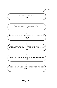
[0053] FIG. 4 illustrates example operations 400 for a process to determine a
set physical
orientation of a satellite antenna. The operations 400 may include an
installation operation 402
in which the satellite antenna is installed in a set physical orientation. As
described above, the
installation operation 402 may be performed by an end user, trained
technician, or some other
user. In any regard, the installation operation 402 may include securing the
satellite antenna
relative to mounting structure to statically dispose the satellite antenna in
the set physical
orientation.
[0054] The operations 400 may also include a location determining operation
404 in
which a location of the antenna as installed is determined. As described
above, the location
determining operation 404 may be performed by a location module. In one
example, the
location determining operation 404 may include resolving the location of the
satellite antenna
relative to the Earth using a GPS receiver. This may provide an accurate
determination of the
latitude, longitude, and elevation of the satellite antenna relative to the
Earth.
[0055] A scanning operation 406 may be performed in which a steerable beam of
the
satellite antenna is scanned through a range of azimuth angles and elevation
angles. That is,
the satellite antenna may have a scan angle describing an angle with respect
to the satellite's
boresight direction that the steerable main beam may be directed, effectively
providing a field
of view of the satellite antenna. Concurrently with the scanning operation
406, a measuring
operation 408 may measure a received signal strength indicator (RSSI) for one
or more signals.
CA 03210645 2023- 8- 31
WO 2022/191820
PCT/US2021/021415
[0056] As described above, the signals may comprise beacon signals
specifically
provided for the purpose of determining a direction of incidence of the signal
relative to the
antenna. Other types of signals may also be utilized in conjunction with or as
an alternative to
the one or more beacon signals. For example, a signal may be received from a
satellite of the
satellite communication system. In such an example, the satellite antenna may
be able to
receive system control messages either via the reception of a satellite signal
or via another
communication network. In turn, the satellite antenna may be able to identify
the satellite from
the system control messages. This function may be provided by the user
terminal to acquire
and establish communication with a satellite of the satellite system_
[0057] Alternatively, if a satellite from outside of the satellite
communication system is
to be utilized to receive one or more of the plurality of signals, reception
of such a signal may
be according to publicly available information. For instance, if the satellite
is a GPS satellite,
the GPS protocol may be publicly available for use in acquiring such a signal
and/or
determining the location of the satellite in an orbital location (e.g., based
on publicly available
ephemeris data). If the satellite comprises a third party proprietary
satellite outside the satellite
commination system, there may be provided public information in the license
filings or other
public record for such a satellite. This public information may allow the
satellite antenna to
match frequencies, carrier bandwidth, modulation type, or other signal
characteristic that may
be referred to as an external signal characteristic. External signal
characteristics may be
perceptible by a receiver without having to interpret or demodulate a signal.
As such,
information derived from external signal characteristics may be determined and
used to identify
a direction of incidence from a satellite in a known location (e.g., based on
publicly available
ephemeris data) without needing to demodulate or receive messages associated
with the signal.
Rather, the system may compare external signal characteristics of the signal
to a public or
otherwise accessible database of those characteristics to uniquely identify
the satellite in
question.
[0058] Moreover, the system may attempt to receive a signal first from
satellites within
the satellite communication system. If none are available, the system may
attempt to receive
signals from publicly accessible systems (e.g., GPS signals). Finally, if no
satellite
communication system signals or publicly accessible signals are available,
proprietary third
party signals with publicly available external characteristics may be
utilized. Further still, in an
example, at least one of the signals may be received from a non-satellite
transmitter such as an
unmanned aerial vehicle (UAV), manned flight platform, balloon, or other
transmitter
16
CA 03210645 2023- 8- 31
WO 2022/191820
PCT/US2021/021415
platforms at known locations relative to Earth. In such examples, the location
of the non-
satellite transmitter may be otherwise known or derived (e.g., using UPS or
the like).
[0059] In turn, the scanning operation 406 and measuring operation 408 may
generate
information regarding the signal strength over the scanned angles for a
plurality of signals
received from two or more satellites. As described above, the satellites may
be in known orbital
locations relative to Earth. For example, ephemeris data for the satellites
may be known or
obtained to allow the precise location of the satellites at the time of
transmission of the signals
to be determined. In any regard, the information regarding the orbital
location of the satellites
from which the plurality of signals are received may be used in a determining
operation 410 in
which a direction of incidence is determined for the respective plurality of
signals.
[0060] In an example, the scanning operation 406 may include scanning the beam
of the
antenna over a full extent of azimuth and elevation angles to which the beam
of the antenna
may be steered (e.g., through a full sweep of all scan angles relative to the
boresight direction).
The scanning operation 406 may include a full power scan in which the beam of
the
electronically steerable antenna is controlled. In another example, the beam
may be broadened
such that a broader radiation spread sensitivity is provided with less
reception gain. The broader
radiation pattern sensitivity with less maximum reception gain may be used to
initially scan
more quickly over the azimuth and elevation angles of the scan due to the
broader radiation
spread sensitivity of the beam. Once a signal has been initially located, a
subsequent scan may
be conducted using a more narrow beam with higher gain in a more limited
extent of the
azimuth and elevation angle range than as identified by the initial broad-beam
scan.
[0061] The receipt of a plurality of signals from one or more satellites is
further
illustrated in FIG. 5. FIG. 5 illustrates a satellite antenna 520 at a known
location on the Earth
530 (e.g., as determined by a GPS receiver). The satellite antenna 520 may be
controlled to
scan a beam over a range of azimuth and elevation angles. During the course of
the scanning,
the RSSI for signals 514, 516 may be measured. The signals 514, 516 may be
received from at
least two different satellites 510, 512 in known orbital locations.
[0062] As may be appreciated from the foregoing disclosure, when determining
the
orientation of the antenna 520, unknown variables include the azimuth angle,
the elevation
angle, and the rotation of the satellite antenna 520. For these three
unknowns, a system of
equations may be generated to solve for the three unknowns of the azimuth
angle, the elevation
angle, and the rotation of the satellite antenna 520. The system of equations
may be solved
using three inputs related to the unknown angles comprising the orientation of
the antenna 520.
17
CA 03210645 2023- 8- 31
WO 2022/191820
PCT/US2021/021415
As such, the known location of the antenna 520 on the Earth may represents a
first input. In
this regard, two or more signals received at the antenna 520 from satellites
510, 512 at known
orbital locations (e.g., using the ephemeris data for the satellites 510, 512)
may provide the
additional at least two inputs to create a determined equation system to allow
for solving for
the three unknowns. Therefore, at least two signals 514, 516 may be received.
In one example,
a signal 514, 516 may be received from each of a plurality of satellites 510,
512 to provide the
necessary two inputs to the system of equations to solve for the set physical
orientation of the
antenna 520. Corresponding directions of incidence for each of the signals may
be determined
(e.g., based on where the signal strength for the respective beacon signal was
greatest during
the scan in view of the known location of the satellite antenna 520 on Earth
and the known
orbital locations of the satellites 510, 512). The directions of incidence for
the signals 514, 516
may provide the necessary remaining two inputs to provide a determined system
to determine
the azimuth angle, elevation angle, and rotation angle for the antenna 520.
[0063] As is illustrated in FIG. 5, the two satellites 510, 512 may be in
different orbital
locations relative to the antenna 520. Use of two different satellites in
different orbital locations
relative to the antenna 520 may provide improved geometric dilution of
precision (GDOP)
values. However, it may be possible to measure two or more signals from the
same satellite at
different times in which the satellite is at different orbital locations to
provide sufficient GDOP.
In further examples, the satellites 510, 512 may each be GEO satellites at
known orbital
locations in the GEO arc. In another example, one or both of the satellites
510, 512 may be
non-GEO satellites. In the case of non-GEO satellites, ephemeris data for a
time at which the
signals 514, 516 were transmitted may be available to the antenna 520 to allow
for precises
orbital location of the non-GEO satellite to be determined at the time the
signal 514, 516 is
received.
[0064] With returned reference to FIG. 4, a resolving operation 412 may
include
resolving the azimuth angle, elevation angle, and rotation angle for the
satellite antenna. The
resolving operation 412 may include constructing and/or solving the system of
equations
described above that utilize the location of the antenna on Earth and the two
directions of
incidence for the signals received at the antenna from known orbital locations
of the respective
satellites from which the signals are received as inputs to solve for the
three unknown variables
of the azimuth angle, elevation angle, and rotation angle for the satellite
antenna.
[0065] The resolving operation 412 may determine the set physical orientation
of the
satellite antenna to a precision of less than 1 degree. For example, the
resolving operation 412
18
CA 03210645 2023- 8- 31
WO 2022/191820
PCT/US2021/021415
may determine the set physical orientation of the satellite antenna to a
precision of not more
than about 0.5 degree, 0.1 degree, or 0.01 degree. In this regard, the
precision achieved through
the resolving operation 412 based on the received signals at the satellite
antenna may far exceed
the precision that may be achieved through physical measurement or a user
aiming the satellite
antenna through manipulation of the satellite antenna relative to a mounting
bracket. With the
more precise orientation determination, angles of avoidance relative to non-
target satellites
may be reduced. In turn, the number of interference mitigation operations may
be reduced
based on the reduce avoidance angles that may be achieved in view of precise
satellite antenna
orientation determination.
[0066] FIG. 6 illustrates example operations 600 for mitigation of
interference at an
electronically steerable satellite antenna. The operations 600 include a
determining operation
602 for determining a set physical orientation of the satellite antenna. The
determining
operation 602 may include the operations 400 described in relation to FIG. 4
above without
limitation.
[0067] The operations 600 may also include an obtaining operation 604 to
obtain
radiation pattern information for the antenna. The radiation pattern
information may be
received at the antenna or may be determined locally. The information
regarding the radiation
pattern may comprise a beam pattern emission profile. For instance, for a
phased array antenna,
known equations may be provided for modelling the radiation pattern of the
antenna.
Specifically, the beam pattern emission profile of the antenna may be modeled
for any direction
in which the beam of the antenna is steered through all available scan angles
relative to
boresight direction for the antenna.
[0068] In turn, the operations 600 may also include an associating operation
606 in which
the transmit radiation pattern for the antenna is associated with (e.g.,
aligned relative to) the set
physical orientation. For instance, the beam pattern emission profile may be
characterized as
radiation vectors of various magnitudes relative to the beam direction of the
antenna. As the
orientation may characterize the boresight direction of the antenna in a
global coordinate
system relative to the Earth, the associating operation 606 may include
translating the radiation
pattern to the global coordinate system such that the radiation pattern may be
described or
expressed in relation to the Earth for any available scan angle of the beam of
the antenna.
[0069] In turn, the operations 600 may include an analysis operation 608 in
which the
radiation transmit vectors describing the transmit radiation pattern of the
antenna are analyzed
to identify any potential interreference events. The potential interference
events may be
19
CA 03210645 2023- 8- 31
WO 2022/191820
PCT/US2021/021415
determined in relation to the main beam of the radiation pattern and/or one or
more side lobes
of off-axis emissions. The analysis operation 608 may include ingestion of
ephemeris data for
non-target satellites and target satellites (e.g., from a scheduler 330). A
relative location of a
GEO arc to the antenna may be determined and avoidance angles relative thereto
may be
established. Additionally or alternatively, avoidance angles may be
established relative to one
or more non-GEO non-target satellites. In any regard, avoidance angles may be
determined in
which radiation emission must be maintained at or below a threshold value.
[0070] An identifying operation 610 may occur when it is determined that an
interference
event in which radiation emission from the antenna reaches a threshold value
in an avoidance
angle. The identifying operation 610 may be conducted in view of ephemeris
data received
during the analysis operation 608. Moreover, in connection with the
identifying operation 610,
ephemeris data may also be analyzed to determine options for interference
mitigation. For
example, in connection with identifying an interference event, it may also be
determined if a
new target satellite is in view of the satellite antenna and whether re-
targeting the satellite
antenna to the new target satellite would mitigate interference. It may be
appreciated that at a
non-GEO user terminal, retargeting the satellite antenna may occur regularly
in view of target
satellites transitioning out of view from the satellite antenna. Thus, re-
targeting to a new target
satellite in response to identifying an interference event may comprise an off-
schedule
transition. The off-schedule transition may correspond to a planned transition
that may be
performed ahead of schedule to mitigate the interference event. Alternatively,
the identifying
operation 610 may include identifying a new target satellite that was not
previously scheduled
for targeting by the satellite antenna in response to identifying the
interference event.
[0071] The identifying operation 610 may be performed locally at the antenna
and/or
user terminal or may be conducted remotely. For instance, the scheduler module
may be located
at the antenna and may be regularly populated with updated with ephemeris
data. Thus, the
user terminal may autonomously determine a schedule of target satellites
including any re-
targeting to mitigate interference events and coordinate such schedule
directly with the target
satellites to maintain continuous communication between the satellite antenna
and at least one
target satellite. Alternatively, such scheduling may be performed remotely
from the user
terminal and the schedule may be communicated to the user terminal for
execution. Of note,
the identifying operation 610 may identify any such interference event
prospectively based on
forecast ephemeris data for target satellites and non-target satellites before
the actual
occurrence of the interference event.
CA 03210645 2023- 8- 31
WO 2022/191820
PCT/US2021/021415
[0072] Moreover, the interference event may be identified in the identifying
operation
610 as relating to the main beam of the satellite antenna or off-axis
emissions as noted above.
With further reference to FIG. 7, an example scenario 700 is depicted. In FIG.
7, a satellite
antenna 720 is steering a main beam 722 of the transmit radiation pattern 730
along a main
beam axis 724 in the direction of a target satellite 710. Of note, the main
beam axis 724 may
be outside of any avoidance angles with respect to either the GEO arc or a non-
target satellite.
However, the radiation pattern 730 may also have off-axis emissions including
a side lobes
726a and 726b. As may be appreciated, side lobe 726b may not be in
interference with any
non-target satellite. However, side lobe 726a may extend along side lobe axis
728a. As may he
appreciated, side lobe axis 728a may be in an avoidance angle relative to non-
target satellite
712. Moreover, the magnitude of the radiation emission of the side lobe 726a
may reach a
threshold value for interference with the non-target satellite 712. Thus, in
FIG. 7 an interference
event may be identified in relation to the side lobe 726a. In turn, the
radiation pattern 730 and/or
other transmission characteristic of the antenna 720 may be modified as
described below to
mitigate the potential interference between the side lobe 726a and the non-
target satellite 712.
[0073] With returned reference to FIG. 6, in response to the identifying
operation 610, a
modifying operation 612 may be performed in which a transmission from the
satellite antenna
is modified. The modifying operation 612 may include re-targeting a new target
satellite such
that the interference event may be avoided. Such information for alternative
target satellites
may be provided by a scheduler 330 or the like. Additionally or alternatively,
the beam shape
of the radiation pattern of the satellite antenna may be modified to avoid
interference. This may
include modifying the radiation pattern shape and/or power to reduce any
radiation directed
within an avoidance angle with a non-target satellite below a threshold level.
[0074] FIG. 8 illustrates an example schematic of a computing device 800
suitable for
implementing aspects of the disclosed technology including an antenna
controller 850 and/or
an orientation determination module 852 corresponding to the examples
described above. The
computing device 800 includes one or more processor unit(s) 802, memory 804, a
display 806,
and other interfaces 808 (e.g., buttons). The memory 804 generally includes
both volatile
memory (e.g., RAM) and non-volatile memory (e.g., flash memory). An operating
system 810,
such as the Microsoft Windows operating system, the Apple macOS operating
system, or the
Linux operating system, resides in the memory 804 and is executed by the
processor unit(s)
802, although it should be understood that other operating systems may be
employed.
21
CA 03210645 2023- 8- 31
WO 2022/191820
PCT/US2021/021415
[0075] One or more applications 812 are loaded in the memory 804 and executed
on the
operating system 810 by the processor unit(s) 802. Applications 812 may
receive input from
various input local devices such as a microphone 834, input accessory 835
(e.g., keypad,
mouse, stylus, touchpad, joystick, instrument mounted input, or the like).
Additionally, the
applications 812 may receive input from one or more remote devices such as
remotely-located
smart devices by communicating with such devices over a wired or wireless
network using
more communication transceivers 830 and an antenna 838 to provide network
connectivity
(e.g., a mobile phone network, Wi-Fi , Bluetooth0). The computing device 800
may also
include various other components, such as a positioning system (e.g., a global
positioning
satellite transceiver), one or more accelerometers, one or more cameras, an
audio interface
(e.g., the microphone 834, an audio amplifier and speaker and/or audio jack),
and storage
devices 828. Other configurations may also be employed.
[0076] The computing device 800 further includes a power supply 816, which is
powered
by one or more batteries or other power sources and which provides power to
other components
of the computing device 800. The power supply 816 may also be connected to an
external
power source (not shown) that overrides or recharges the built-in batteries or
other power
sources.
[0077] In an example implementation, the computing device 800 comprises
hardware
and/or software embodied by instructions stored in the memory 804 and/or the
storage devices
828 and processed by the processor unit(s) 802. The memory 804 may be the
memory of a host
device or of an accessory that couples to the host. Additionally or
alternatively, the computing
device 800 may comprise one or more field programmable gate arrays (FPGAs),
application
specific integrated circuits (ASIC), or other hardware/software/firmware
capable of providing
the functionality described herein.
[0078] The computing device 800 may include a variety of tangible processor-
readable
storage media and intangible processor-readable communication signals.
Tangible processor-
readable storage can be embodied by any available media that can be accessed
by the
computing device 800 and includes both volatile and nonvolatile storage media,
removable and
non-removable storage media. Tangible processor-readable storage media
excludes intangible
communications signals and includes volatile and nonvolatile, removable and
non-removable
storage media implemented in any method or technology for storage of
information such as
processor-readable instructions, data structures, program modules or other
data. Tangible
processor-readable storage media includes, but is not limited to, RAM, ROM,
EEPROM, flash
22
CA 03210645 2023- 8- 31
WO 2022/191820
PCT/US2021/021415
memory or other memory technology, CDROM, digital versatile disks (DVD) or
other optical
disk storage, magnetic cassettes, magnetic tape, magnetic disk storage or
other magnetic
storage devices, or any other tangible medium which can be used to store the
desired
information and which can be accessed by the computing device 800. In contrast
to tangible
processor-readable storage media, intangible processor-readable communication
signals may
embody processor-readable instructions, data structures, program modules or
other data
resident in a modulated data signal, such as a carrier wave or other signal
transport mechanism.
The term "modulated data signal" means an intangible communications signal
that has one or
more of its characteristics set or changed in such a manner as to encode
information in the
signal. By way of example, and not limitation, intangible communication
signals include
signals traveling through wired media such as a wired network or direct-wired
connection, and
wireless media such as acoustic, RF, infrared, and other wireless media.
[0079] Some implementations may comprise an article of manufacture. An article
of
manufacture may comprise a tangible storage medium to store logic. Examples of
a storage
medium may include one or more types of processor-readable storage media
capable of storing
electronic data, including volatile memory or non-volatile memory, removable
or non-
removable memory, erasable or non-erasable memory, writeable or re-writeable
memory, and
so forth. Examples of the logic may include various software elements, such as
software
components, programs, applications, computer programs, application programs,
system
programs, machine programs, operating system software, middleware, firmware,
software
modules, routines, subroutines, operation segments, methods, procedures,
software interfaces,
application program interfaces (API), instruction sets, computing code,
computer code, code
segments, computer code segments, words, values, symbols, or any combination
thereof. In
one implementation, for example, an article of manufacture may store
executable computer
program instructions that, when executed by a computer, cause the computer to
perform
methods and/or operations in accordance with the described implementations.
The executable
computer program instructions may include any suitable type of code, such as
source code,
compiled code, interpreted code, executable code, static code, dynamic code,
and the like. The
executable computer program instructions may be implemented according to a
predefined
computer language, manner or syntax, for instructing a computer to perform a
certain operation
segment. The instructions may be implemented using any suitable high-level,
low-level, object-
oriented, visual, compiled and/or interpreted programming language.
23
CA 03210645 2023- 8- 31
WO 2022/191820
PCT/US2021/021415
[0080] One general aspect of the present disclosure includes a method for
determining a
set physical orientation of an electronically steerable satellite antenna for
use in a satellite
communication system. The method includes determining a location of the
electronically
steerable satellite antenna relative to Earth. The method also includes
receiving a plurality of
signals from at least two different respective satellites. The method includes
electronically
steering a beam of the electronically steerable satellite antenna to determine
a direction of
incidence of each of the plurality of signals with respect to a boresight
direction of to the
electronically steerable satellite antenna. In turn, the method includes
calculating a set physical
orientation of the electronically steerable satellite antenna relative to the
Earth based on the
location of the electronically steerable satellite antenna and the directions
of incidence of each
of the signals from the satellites. The satellites from which the plurality of
signals are received
are in known orbital locations relative to the Earth The set physical
orientation comprises an
azimuth angle, an elevation angle, and a rotation of the boresight direction
of the electronically
steerable satellite antenna relative to the Earth.
[0081] Implementations may include one or more of the following features. For
example,
the method may also include determining a beam pattern emission profile for
the electronically
steerable satellite antenna and associating the beam pattern emission profile
to the set physical
orientation of the electronically steerable satellite antenna. In an example,
the beam pattern
emission profile is asymmetric.
[0082] In an example the method includes steering the beam of the
electronically
steerable satellite antenna to communicate a signal between the electronically
steerable satellite
antenna and a target satellite and detecting an interference event based on
the beam pattern
emission profile for the electronically steerable satellite antenna in the set
physical orientation.
The interference event may include emissions from the electronically steerable
satellite antenna
reaching a predetermined level with respect to a non-target satellite. In an
example, the
interference event may be based on a side lobe emission apart from a main beam
emission of
the beam pattern emission profile.
[0083] The method may include modifying a transmission of the electronically
steerable
satellite antenna in response to the interference event. In an example, the
interference event
may be with respect to a non-target satellite geosynchronous orbit.
Additionally or
alternatively, an interference event may be with respect to a non-target
satellite in low earth
orbit.
24
CA 03210645 2023- 8- 31
WO 2022/191820
PCT/US2021/021415
[0084] In an example, the electronically steerable satellite antenna may be a
phased array
satellite antenna. The determining the direction of incidence of each of the
plurality of signals
with respect to the boresight direction of the electronically steerable
satellite antenna may
include electronically steering the beam of the electronically satellite
antenna to scan over a
range of azimuth angles and a range of elevation angles. The direction of
incidence of each of
the plurality of signals may be determined based on a signal strength
indication of the signal
relative to the range of azimuth angles and the range of elevation angles.
[0085] In an example, at least one of the two different respective satellites
comprises a
geosynchronous satellite. In an example, at least one of the two different
respective satellites
may be a low earth orbit satellite. As such, the known orbital location
relative to the Earth may
be based on ephemeris data of the low earth orbit satellite at a time
reference corresponding to
receipt of a signal from the low earth orbit satellite.
[0086] In an example, the calculating the set physical orientation may include
resolving
the azimuth angle, the elevation angle, and the rotation to within not more
than about 1 degree
of error.
[0087] Another general aspect of the present disclosure includes a system
operative to
determine an orientation of an electronically steerable satellite antenna for
use in a satellite
communication system. The system includes an electronically steerable
satellite antenna. The
electronically steerable satellite antenna electronically steers a beam of the
electronically
steerable satellite antenna to receive a plurality of signals from at least
two different respective
satellites. The system also includes a location module to determine a location
of the
electronically steerable satellite antenna relative to Earth. The system
further includes an
orientation calculation module to determine a direction of incidence of each
of the plurality of
signals with respect to a boresight direction of the electronically steerable
satellite antenna in
view of known orbital locations relative to Earth. to the orientation
calculation module is
further calculates a set physical orientation of the electronically steerable
satellite antenna
relative to the Earth based on the location of the electronically steerable
satellite antenna and
the directions of incidence of each of the plurality of signals. The set
physical orientation
includes an azimuth angle, an elevation angle, and a rotation of the boresight
direction of the
electronically steerable satellite antenna relative to the Earth.
[0088] Implementations may include one or more of the following features. For
example
the electronically steerable satellite antenna may have a beam pattern
emission profile. In turn,
the orientation calculation module may associate the beam pattern emission
profile to the set
CA 03210645 2023- 8- 31
WO 2022/191820
PCT/US2021/021415
physical orientation of the electronically steerable satellite antenna. In an
example, the beam
pattern emission profile may be asymmetric.
[0089] In an example, the electronically steerable satellite antenna may steer
the beam
of the electronically steerable satellite antenna to communicate a signal
between the
electronically steerable satellite antenna and a target satellite. The system
may include a
scheduler to detect an interference event based on the beam pattern emission
profile for the
electronically steerable satellite antenna in the set physical orientation.
The interference event
may include emissions from the electronically steerable satellite antenna
reaching a
predetermined level with respect to a non-target satellite. In an example, the
interference event
may be based on a side lobe emission apart from a main beam emission of the
beam pattern
emission profile. The electronically steerable satellite antenna may modify a
transmission in
response to and prior to the interference event.
[0090] In an example, the interference event may be with respect to a non-
target satellite
in geosynchronous orbit. Additionally or alternatively, an interference event
may be with
respect to non-target satellite in low earth orbit.
[0091] In an example, the electronically steerable satellite antenna may be a
phased array
antenna. The orientation calculation module may determine the direction of
incidence of each
of the plurality of signals with respect to the boresight direction of the
electronically steerable
satellite antenna by electronically steering the beam of the electronically
steerable satellite
antenna to scan over a range of azimuth angles and a range of elevation angles
to identify the
direction of incidence. The direction of incidence of each of the plurality of
signals may be
determined based on a signal strength indication of the plurality of signals
relative to the range
of azimuth angles and the range of elevation angles.
[0092] In an example, at least one of the two different respective satellites
comprises a
geosynchronous satellite. Additionally or alternatively, at least one of the
two different
respective satellites may be a low earth orbit satellite and the known orbital
location relative to
the Earth is based on ephemeris data of the low earth orbit satellite at a
time reference
corresponding to receipt of a signal from the low earth orbit satellite.
[0093] In an example, the orientation calculation module may resolve the
azimuth angle,
the elevation angle, and the rotation to within not more than about 1 degree
of error.
[0094] The implementations described herein are implemented as logical steps
in one or
more computer systems. The logical operations may be implemented (1) as a
sequence of
processor-implemented steps executing in one or more computer systems and (2)
as
26
CA 03210645 2023- 8- 31
WO 2022/191820
PCT/US2021/021415
interconnected machine or circuit modules within one or more computer systems.
The
implementation is a matter of choice, dependent on the performance
requirements of the
computer system being utilized. Accordingly, the logical operations making up
the
implementations described herein are referred to variously as operations,
steps, objects, or
modules. Furthermore, it should be understood that logical operations may be
performed in any
order, unless explicitly claimed otherwise or a specific order is inherently
necessitated by the
claim language.
[0095] While the invention has been illustrated and described in detail in the
drawings
and foregoing description, such illustration and description is to be
considered as exemplary
and not restrictive in character. For example, certain embodiments described
hereinabove may
be combinable with other described embodiments and/or arranged in other ways
(e.g., process
elements may be performed in other sequences). Accordingly, it should be
understood that
only the preferred embodiment and variants thereof have been shown and
described and that
all changes and modifications that come within the spirit of the invention are
desired to be
protected.
[0096] For the purposes of this disclosure, unless otherwise indicated, all
numbers
expressing amounts, sizes, dimensions, proportions, shapes, formulations,
parameters,
percentages, quantities, characteristics, and other numerical values used in
the specification
and claims, are to be understood as being modified in all instances by the
term "about" even
though the term "about" may not expressly appear with the value, amount or
range.
Accordingly, unless indicated to the contrary, the numerical parameters set
forth herein are not
and need not be exact, but may be approximate and/or larger or smaller as
desired, reflecting
tolerances, conversion factors, rounding off, measurement error and the like,
and other factors
known to those of skill in the art depending on the desired properties sought
to be obtained by
the presently disclosed subject matter. For example, the term "about," when
referring to a value
can be meant to encompass variations of, in some examples +/- 100%, in some
examples +/-
50%, in some examples +/- 20%, in some examples +/- 10%, in some examples +/-
5%, in
some examples +/- 1%, in some examples +/- 0.5%, and in some examples +/- 0.1%
from the
specified amount, as such variations are appropriate to perform the disclosed
methods.
[0097] Further, the term "about" when used in connection with one or more
numbers or
numerical ranges, should be understood to refer to all such numbers, including
all numbers in
a range and modifies that range by extending the boundaries above and below
the numerical
values set forth. The recitation of numerical ranges by endpoints includes all
numbers, e.g.,
27
CA 03210645 2023- 8- 31
WO 2022/191820
PCT/US2021/021415
whole integers, including fractions thereof, subsumed within that range (for
example, the
recitation of 1 to 5 includes 1, 2, 3, 4, and 5, as well as fractions thereof,
e.g., 1.5, 2.25, 3.75,
4.1, and the like) and any range within that range.
28
CA 03210645 2023- 8- 31