Note: Descriptions are shown in the official language in which they were submitted.
SELF-DRILLING ANCHOR INSERTER
CROSS-REFERENCE TO RELATED APPLICATION
[0001] The
present application claims priority to and the benefit of U.S. Provisional
Patent
Application Number 62/781,246, filed on December 18, 2018 and entitled "Self-
Drilling
Anchor Inserter. ". The
present
application relates to U.S. Provisional Patent Application Number 62/572369
filed on October
13, 2017, U.S. Provisional Patent Application Number 62/618851, filed on
January 18, 2018,
U.S. Provisional Patent Application Number 62/631034, filed on February 15,
2018, U.S.
Provisional Patent Application Number 62/543,516, filed on August 10,2017,
U.S. Provisional
Patent Application Number 62/536208, filed on July 24, 2017.
BACKGROUND OF THE INVENTION
1. Field of the Invention
[0002] The
present invention relates to drills, anchor drivers, and a drill guide for
drilling
a bone hole at a surgical repair site and inserting a suture anchor in the
bone hole and, more
particularly, to a self-drilling all-suture anchor and inserter.
2. Description of Related Art
[0003] Many
orthopedic surgical and medical procedures require the fixation of one body
to another body. Such bodies may include bone, soft tissue, and prosthetics.
One body can be
fixed in a position relative to another using connector devices, such as
screws and suture
anchors (e.g., cannulated knotless suture anchors and soft all suture
anchors). For example,
various orthopedic surgeries require the insertion and fixation of a suture
anchor within a bone.
[0004] One
example of a suture anchor is a soft suture anchor, such as the Y-Knot
device.
See, e.g., U.S. 9826971. Since soft anchors are commonly made entirely of
suture materials,
they are sometimes called "all-suture" anchors, and generally include a
fibrous construct
anchor body portion (or fibrous, braided or woven fabric-type structure such
as a flexible web,
as described in U.S. Pat. No. 9173652) and a suture or filament portion. In a
traditional Y-
Knot device, the suture is pierced entirely through the braid material a
number of times, such
that the suture passes through a "front" surface and a "back" surface. When a
Y-Knot anchor
is constructed in the traditional manner, the segments of suture on the back
surface of the braid
are in contact with bone and can be abraded by the bone due to friction.
[0005] There
are at least two general, conventional methods for inserting a suture anchor
within a bone. In one method, a bone hole is created and prepared using a
drill bit. The drill bit
is typically advanced through a drill guide to create the bone hole and then,
a suture anchor is
1
Date Recue/Date Received 2023-08-31
passed through or down the drill guide into the bone hole for deployment. If
the drill guide is
moved between creation of the bone hole and advancement of the suture anchor,
the drill guide
may be moved out of alignment with the bone hole. If the drill guide is no
longer aligned with
the bone hole, the suture anchor often cannot be inserted and deployed.
Therefore, the creation
of a second bone hole is often required when drill guide moves out of
alignment with the first
bone hole.
100061 In a second method, the drilling step is eliminated in an
attempt to avoid the
aforementioned misalignment issue. A self-punching suture anchor, such as the
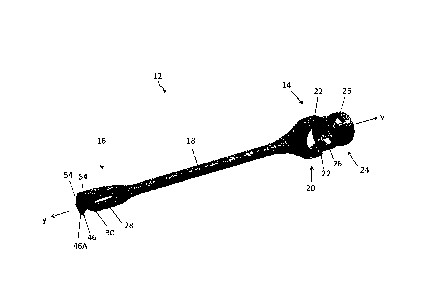
Y-Knot RC
Suture Anchor, for example, is designed with an inserter that allows the
anchor in the inserter
to be directly positioned on the bone at the desired location. When the anchor
in the inserter is
positioned at the desired location, the inserter can be hammered, forcing the
anchor directly
into the bone. However, hammering the anchor into the bone imparts impact
forces to the bone
which may be undesirable for some surgical site locations. For example, impact
forces may be
particularly undesirable at the glenoid bone or smaller bones, such as in the
extremities.
Further, self-punching anchors are generally required to be larger in size,
Thus, such anchors
may not only be undesirable but unusable in smaller bones.
100071 Therefore, there is a need for a suture anchor inserter that
can insert a small suture
anchor into the bone without the need to drill a bone hole or to impart impact
forces on the
bone and which can achieve the minimum hole size that results when an anchor
is not
contributing to the enlargement of the hole.
100081 Description of the Related Art Section Disclaimer: To the
extent that specific
patents/publications/products are discussed above in this Description of the
Related Art Section
or elsewhere in this disclosure, these discussions should not be taken as an
admission that the
discussed patents/publications/products are prior art for patent law purposes.
For example,
some or all of the discussed patents/publications/products may not be
sufficiently early in time,
may not reflect subject matter developed early enough in time and/or may not
be sufficiently
enabling so as to amount to prior art for patent law purposes.
BRIEF SUMMARY OF THE INVENTION
2
Date Recue/Date Received 2023-08-31
[0009] Embodiments of the present invention recognize that there are
potential problems
and/or disadvantages with the conventional methods for drilling a bone hole
and inserting a
suture anchor (as discussed herein and above). For example, removing a drill
bit from the drill
guide and replacing it with a driver to insert the suture anchor increases the
risk of misalignment
of the drill guide with the bone hole, which requires additional surgical time
and risks trauma
to the surrounding tissue and bone. In another example, hammering the anchor
into the bone
imparts impact forces to the bone which may be undesirable for some surgical
site locations.
Therefore, a need exists for a simple-to-use suture anchor inserter that can
insert a suture anchor
into the bone without the need to drill a bone hole or to impart impact forces
on the bone and
which can achieve the minimum hole size that results when an anchor is not
contributing to the
enlargement of the hole. Various embodiments of the present invention may be
advantageous
in that they may solve or reduce one or more of the potential problems and/or
disadvantages
discussed herein.
[0010] The present disclosure is directed to an inventive configuration,
structure, and
resulting function of a self-drilling anchor inserter configured to insert
suture anchors into
bone. According to one aspect, the present invention is an anchor inserter.
The anchor inserter
includes an inserter tube extending along a longitudinal axis having a
proximal inserter end and
a distal inserter end. The inserter also includes an inserter tip attached to
and extending distally
from the distal inserter end. The inserter tip has a proximal tip end and a
distal tip end with a
suture anchor retention slot extending through the distal tip end. The
inserter has one or more
cutting edges extending at least a partially along an outer perimeter edge of
the distal tip end.
The distal tip end has a first arm and a second arm. The first arm is
substantially straight and
the second arm is curved.
[0011] According to another aspect, the present invention is an anchor
inserter including
a cannulated inserter tube which extends along a longitudinal axis and has a
proximal inserter
end and distal inserter end. The anchor inserter also includes a cannulated
suture tube
extending through the cannulated inserter tube. The cannulated suture tube has
a proximal
suture end and a distal suture end. The anchor inserter further includes an
inserter tip attached
to and extending distally from the distal inserter end. The inserter tip has a
proximal tip end
and a distal tip end. One or more features on the proximal tip end are
removably connected to
one or more features on the distal inserter end.
[0012] According to yet another aspect, the present invention is an
anchor inserter system
further including a cannulated inserter tube extending along a longitudinal
axis and having a
3
Date Recue/Date Received 2023-08-31
proximal inserter end and distal inserter end. The system also includes a
cannulated suture
tube extending through the cannulated inserter tube. The cannulated suture
tube has a proximal
suture end and a distal suture end. The system further includes an inserter
tip attached to and
extending distally from the distal inserter end. A suture anchor retention
slot extends through
the inserter tip and an anchor with a length of suture positioned therethrough
extends through
the suture anchor retention slot. The length of suture extends proximally
along the inserter tip.
[0013] Suture
material or sutures, as the terms are used and described herein, can include
monofilarnent or multi-filament suture as well as any other metallic or non-
metallic filamentary
or wire-like material suitable for performing the function of a suture. This
material can include
both bioabsorbable and non-absorbable materials.
[0014] Suture
anchors, as the term is used herein, can include soft suture anchors and rigid
suture anchors. Soft suture anchors are formed from filaments of suture
material which are
retained within pre-formed bone holes by being deformable to increase their
diameter to a size
greater than that of the bone hole, to thereby reside within the cancellous
bone and under the
bone cortex. One such suture anchor is disclosed in U.S. Patent No. 9826971
assigned to the
assignee hereof. Since
soft anchors are
commonly made entirely of suture materials, they are sometimes called "all-
suture" anchors,
and generally include a fibrous construct anchor body portion (or fibrous,
braided or woven
fabric-type structure such as a flexible web, as described in U.S. Pat. No.
9173652) and a suture
or filament portion. Methods and devices for inserting/deploying such all-
suture anchors are
known, examples of which are disclosed in U.S. Pat. No. 9173652.
[0015] As
described in U.S. Pat. No. 8409252, for example, "non-soft," "hard" or "rigid"
suture anchors generally include a "hard" anchor body portion (that may or may
not include
inner and outer members) and a suture/filament portion. The anchor body of
such suture
anchors may be formed of a biocompatible and/or bioabsorbable material. These
materials
may be of such composition that they are reabsorbed by the body, e.g., during
the healing
process of the bone. Exemplary materials that are suitable for use in the
inner and outer
members include, but are not limited to, polyetheretherketone ("PEEK"),
polylactic acid/beta-
tricalcium phosphate ("PLA/Beta-TCP") composites, ultra-high molecular weight
polyethylene ("UHMWPE"), as well as other metallic, non-metallic, and
polymeric materials.
BRIEF DESCRIPTION OF THE SEVERAL VIEWS OF THE DRAWING(S)
[0016] The
present invention will be more fully understood and appreciated by reading the
following Detailed Description in conjunction with the accompanying drawings.
The
4
Date Recue/Date Received 2023-08-31
accompanying drawings illustrate only typical embodiments of the disclosed
subject matter
and are therefore not to be considered limiting of its scope, for the
disclosed subject matter may
admit to other equally effective embodiments. Reference is now made briefly to
the
accompanying drawings, in which:
100171 FIG. 1 is a perspective view schematic representation of an
inserter tip, according
to an embodiment;
[00181 FIG. 2 is a side view schematic representation of a distal tip end
of the inserter tip,
according to an embodiment;
[0019] FIG. 3 is a side perspective view view schematic representation of
the distal tip end
of the inserter tip, according to an embodiment;
[0020] FIG. 4 is a close-up front view schematic representation of the
distal tip end of the
inserter tip, according to an embodiment;
[0021] FIG. 5 is a close-up perspective view schematic representation of
an anchor
positioned within an anchor retention slot of the inserter tip, according to
an embodiment;
[0022] FIG. 6 is a perspective view schematic representation of the
inserter tip connected
to a suture tube, according to an embodiment;
100231 FIG. 7 is a perspective view schematic representation of the a
distal suture tube end
of the suture tube connected to the inserter tip, according to an embodiment;
[0024] FIG. 8A is a close-up perspective view schematic representation of
the inserter tip
connected to the suture tube, according to an embodiment;
[0025] FIG. 8B is a close-up perspective view schematic representation of
the inserter tip
connected to the suture tube, according to an alternative embodiment;
100261 FIG. 9 is a close-up perspective view schematic representation of
a proximal suture
tube end of the suture tube, according to an embodiment;
[0027] FIG. 10 is a close-up back perspective view schematic
representation of the
proximal suture tube end of the suture tube, according to an embodiment;
[00281 FIG. 11 is a perspective view schematic representation of the self-
drilling anchor
inserter, according to an embodiment;
[0029] FIG. 12 is a close-up perspective view schematic representation of
a distal inserter
end of an inserter tube connected to the inserter tip, according to an
embodiment;
[0030] FIG. 13 is a partial transparent perspective view schematic
representation of the
distal inserter end of the inserter tube connected to the inserter tip;
according to an embodiment;
Date Recue/Date Received 2023-08-31
[00311 FIG. 14 is a close-up view schematic representation of a proximal
inserter end of
the inserter tube, according to an embodiment;
100321 FIG. 15 is a perspective view schematic representation of a guide,
according to an
embodiment;
10033] FIG. 16 is a back perspective view schematic representation of the
guide, according
to an embodiment;
[00341 FIG. 17 is a close-up perspective view schematic representation of
a guide tip,
according to an embodiment;
[0035] FIG. 18 is a close-up perspective view schematic representation of
a guide tip,
according to an alternative embodiment;
[0036] FIG. 19 is a close-up perspective view schematic representation of
a guide tip,
according to another embodiment;
[00371 FIG. 20 is a side perspective view schematic representation of the
self-drilling
anchor inserter in a retracted position, according to an embodiment;
[0038] FIG. 21A is a side perspective view schematic representation of
the distal tip end
of the self-drilling anchor inserter in the retracted position, according to
an embodiment;
100391 FIG. 21B is a close-up front view schematic representation of the
distal tip end of
the inserter tip within the guide tip, according to an embodiment
[00401 FIG. 22 is a side perspective view schematic representation of the
self-drilling
anchor inserter in an extracted position, according to an embodiment;
[0041] FIG. 23 is a side perspective view schematic representation of the
distal end of the
self-drilling anchor inserter in the extracted position, according to an
embodiment;
100421 FIG. 24A is a back view schematic representation of an all-suture
anchor,
according to an embodiment;
[00431 FIG. 24B is a top view schematic representation of the all-suture
anchor of FIG.
24A;
[00441 FIG. 25A is a back view schematic representation of an all-suture
anchor,
according to an embodiment;
[00451 FIG. 25B is a top view schematic representation of the all-suture
anchor of FIG.
25A;
[0046] FIG. 26A is atop view schematic representation of an all-suture
anchor loaded onto
the inserter tip, according to an embodiment;
6
Date Recue/Date Received 2023-08-31
100471 FIG. 269 is a side view schematic representation of the all-suture
anchor loaded
onto the inserter tip of FIG. 26A;
[0048] FIG. 27A is atop view schematic representation of an all-suture
anchor loaded onto
the inserter tip, according to an alternative embodiment;
[0049] FIO. 27B is a side view schematic representation of the all-suture
anchor loaded
onto the inserter tip of FIG. 27A;
100501 FIG. 28A is a top view schematic representation of an all-suture
anchor, according
to an embodiment;
100511 FIG. 28B is a side view schematic representation of the all-suture
anchor in FIG.
28A;
100521 FIG. 29A is a top view schematic representation of an anchor braid
loaded with
two lengths of suture, according to an embodiment;
[0053] FIG. 2913 is a top view schematic representation of an anchor
braid loaded with
two lengths of suture, according to an alternative embodiment;
[0054] FIG. 30A is a top view schematic representation of a threader
passed through an
anchor braid, according to an embodiment;
[0055] FIG. 30B is a top view schematic representation of the anchor
braid of FIG. 30A
with a first end loaded into the threader;
[0056] FIG. 30C is a top view schematic representation of the anchor
braid of FIG. 30A
with a central eyelet;
100571 FIG. 31 is atop view schematic representation of the anchor braid
of FIG. 30C with
a length of suture passing through the central eyelet;
[0058] FIG. 32A is a top view schematic representation of an anchor braid
folded and
stitched, according to an embodiment;
[0059] FIG. 329 a top view schematic representation of an anchor braid of
FIG. 32A with
an additional material covering;
[0060] FIG. 33 is a top view schematic representation of the inserter in
the unloaded, pre-
deployment configuration, according to an alternative embodiment;
[0061] FIG. 34 is a top view schematic representation of the inserter in
the unloaded, pre-
deployment configuration, according to an additional alternative embodiment;
[0062] FIG. 35 is a close-up perspective view schematic representation of
the distal end
of the inserter, according to an embodiment;
7
Date Recue/Date Received 2023-08-31
100631 FIG. 36A is a side view schematic representation of an embodiment
of a suture
anchor in the undeployed state, according to an embodiment;
10064] FIG. 36B is a side view schematic representation of the suture
anchor of FIG. 36A
shortened and expanded in the deployed state, according to an embodiment;
[0065] FIG. 37 is a side view schematic representation of a disposable
handpiece with a
according to an embodiment;
100661 FIG. 38 is a perspective view digital photograph of a soft all-
suture anchor in an
unloaded (not loaded onto an installation device or inserter), pre-deployment
configuration
according to an embodiment;
100671 FIG. 39A is a side view schematic representation of an embodiment
of the all-
suture anchor of FIG. 38 connected to an installation device or inserter in a
pre-deployment
configuration according to an embodiment
100681 FIG. 39B is a side view schematic representation of an embodiment
of the all-
suture anchor of FIG. 38 in a post-deployment configuration positioned in a
bone hole
according to an embodiment;
100691 FIG. 39C is a side view digital photograph of an embodiment of the
all-suture
anchor of FIG. 38 in a post-deployment configuration positioned in a bone hole
according to
an embodiment;
[0070] FIG. 40 is a perspective view digital photograph of a soft all-
suture anchor in an
unloaded (not loaded onto an installation device or inserter), pre-deployment
configuration
according to an embodiment;
100711 FIG. 41A is a side view schematic representation of an embodiment
of the all-
suture anchor of FIG. 40 connected to an installation device or inserter in a
pre-deployment
configuration according to an embodiment;
100721 FIG. 41B is a side view schematic representation of an embodiment
of the all-
suture anchor of FIG. 40 in a post-deployment configuration positioned in a
bone hole
according to an embodiment;
100731 FIG. 4IC is a side view schematic representation of a portion of
an alternative
embodiment of the all-suture anchor according to an embodiment;
100741 FIG. 42 is a side view digital photograph of an embodiment of the
all-suture anchor
of FIG. 40 in a post-deployment configuration after addition of an activator
according to an
embodiment;
8
Date Recue/Date Received 2023-08-31
100751 FIG. 43 is a side view schematic representation of an all-suture
anchor insertion
device according to an alternative embodiment;
[0076] FIG. 44 is a perspective view schematic representation of an all-
suture anchor
insertion device in a pre-deployed configuration and position according to an
alternative
embodiment; and
100771 FIG. 45 is a perspective view schematic representation of an all-
suture anchor
insertion device in a pre-deployed configuration and position according to an
alternative
embodiment,
DETAILED DESCRIPTION OF THE INVENTION
100781 Referring now to the drawings, wherein like reference numerals
refer to like parts
throughout, there is seen a self-drilling anchor inserter 10 (FIG. 11) and its
component parts.
The inserter 10 comprises an inserter tip 12, shown in FIG. 1. FIG. 1 is a
perspective view
schematic representation of the inserter tip 12, according to an embodiment.
The inserter tip
12 has a proximal tip end 14 and a distal tip end 16 with a shaft 18 extending
therebetween.
The shaft 18 extends along a central longitudinal y ¨ y axis. In the depicted
embodiment, the
shaft 18 is solid, although it can be cannulated.
100791 The proximal tip end 14 of the inserter tip 12 includes features
for connecting the
inserter tip 12 to the remainder of the self-drilling anchor inserter 10 (FIG.
11). Specifically,
as shown in FIG. 1, the proximal tip end 14 comprises a tip protrusion portion
20. In the
depicted embodiment, a cross-section of the tip protrusion portion 20 is
substantially triangular.
In other words, the tip protrusion portion 20 is tapered such that its
diameter or width increases
in the proximal direction relative to the central longitudinal y ¨ y axis (or
shaft 18). The tip
protrusion portion 20 comprises one or more protrusions 22. In the depicted
embodiment, the
tip protrusion portion 20 comprises two rectangular protrusions 22 which
extend in the
proximal direction and are spaced such that they are opposing.
[0080] Still referring to FIG. 1, the tip protrusion portion 20 is
connected to a cannulated,
proximal tip tube 24. The proximal tip tube 24 comprises one or more tip
recesses 26 extending
therethrough. In the depicted embodiment, the proximal tip tube 24 comprises
two tip recesses
26 spaced such that they are opposing. As also shown in FIG. 1, the
protrusions 22 of the tip
protrusion portion 20 are substantially aligned with the recesses 26 of the
proximal tip tube 24.
The protrusions 22 and the recesses 26 connect to features on the remainder of
the self-drilling
anchor inserter 10 (FIG. 11), as described in detail below.
9
Date Recue/Date Received 2023-08-31
100811 Turning now to FIG. 2, there is shown a side view schematic
representation of a
distal tip end 16 of the inserter tip 12, according to an embodiment. The
distal tip end 16 of
the inserter tip 12 is generally forked (i.e., pronged) or hook-shaped and has
a total diameter or
width larger than that of the shaft 18. As shown in FIGs. 1 and 2, the distal
tip end 16 comprises
a first arm 28 extending substantially parallel to the central longitudinal y
¨ y axis in the distal
direction. The first arm 28 is substantially straight with a rounded first arm
end 30.
100821 The distal tip end 16 also comprises a second arm 32. The second
arm 32 is
substantially L-shaped, as shown in FIG. 2. The second arm 32 comprises a
straight portion
34 that extends substantially parallel to the central longitudinal y ¨ y axis
and the first arm 28
in the distal direction. The straight portion 34 of the second aiin 32 is
connected to a curved
portion 36. The curved portion 36 comprises an inner perimeter edge 38 that
curves toward
the central longitudinal y ¨ y axis such that the inner perimeter edge
substantially extends at an
angle relative to the central longitudinal y ¨y axis. Stated differently, the
inner perimeter edge
38 of the second arm 32 curves toward an axis extending through the length of
the first arm 28.
100831 The configuration of the first arm 28 and the second arm 32
creates a suture anchor
retention slot 40 therebetween. The suture anchor retention slot 40 also
comprises a straight
portion 42 connected to a curved portion 44 that extends at an angle
therefrom. The suture
anchor retention slot 40 is sized or otherwise configured to hold an anchor
braid and length of
suture of an all-suture anchor, permitting the all-suture anchor to be pushed
into a bone hole
by the inserter tip 12.
100841 Referring now to FIG. 3, there is shown a side perspective view
schematic
representation of the distal tip end 16 of the inserter tip 12, according to
an embodiment. The
inner perimeter edge 38 of the second arm 32 of the distal tip end 16 extends
to a sharp second
arm end 46. The second arm end 46 has an edge 46A that extends substantially
perpendicular
to the central longitudinal y ¨ y axis, as shown in FIG. 1. In FIG. 1 and 2,
the second arm end
46 extends past the first arm end 30 of the first arm 28 to ensure that the
first arm end 30 does
not have significant contact with the bone during drilling.
100851 The second arm 32 also comprises an outer perimeter edge 48 with
an optimized
geometry for drilling. As shown in FIG. 3, the outer perimeter edge 48 of the
second arm 32
has a straight portion 50 that extends substantially parallel to the central
longitudinal y ¨ y axis
in the distal direction. The outer perimeter edge 48 also includes an angle
portion 52. The
angled portion 52 extends at an angle relative to the straight portion 50 (and
the central
longitudinal y ¨ y axis). In addition, the angled portion 52 extends from the
straight portion 50
Date Recue/Date Received 2023-08-31
at angle relative to a lateral x ¨ x axis extending through the suture anchor
retention slot 40, as
shown.
100861 The configuration of the angled portion 52 is due to a recessed
area 54 on the
second arm 32. The angled portion 52 extends to a first end portion 56 of the
outer perimeter
edge 48, as shown in FIG. 3. In the depicted embodiment, the first end portion
56 is
substantially perpendicular relative to the straight portion 50. The first end
portion 56 connects
to a second end portion 58 of the outer perimeter edge 48. The second end
portion 58 extends
along a z ¨ z axis that is substantially perpendicular to the longitudinal y ¨
y axis and/or the
lateral x ¨x axis. Together, the first and second end portions 56, 58 extend
partially around an
end surface 60 of the second arm 32.
1008711 As shown in FIGs. 1 and 3, the second arm 32 comprises two
recessed areas 54,
which are comers of the second arm 32 that have been recessed to create
multiple cutting edges
62 along the second arm 32. The geometry of the distal tip end 16 creates
positive rank angle
and clearance angles at the angled portion 52, the first end portion 56, and
the second end
portion 58, Together, the angled portion 52 and first and second end portions
56, 58 of the
outer perimeter edge 48 are cutting edges 62 for effective cutting action. The
straight portion
50 of the outer perimeter edge 48 is a reaming edge 64.
100881 Turning now to FIG. 4, there is shown a close-up front view
schematic
representation of the distal tip end 16 of the inserter tip 12, according to
an embodiment. In
particular, FIG. 4 shows the circumference c of the final hole created by the
reaming edge 64
(FIG. 3). The final hole is sized and configured to achieve the minimum hole
size that results
when an anchor (e.g., anchor braid) is not contributing to the enlargement of
the hole.
100891 Referring now to FIG. 5, there is shown a close-up perspective
view schematic
representation of an anchor 100 positioned within the suture anchor retention
slot 40 of the
inserter tip 12, according to an embodiment. As shown in FIG. 5, an anchor 100
is positioned
or otherwise wrapped within the suture anchor retention slot 40 such that a
first end 114A of
the anchor 100 and a second end 114B of the anchor 100 extend along opposing
sides of the
distal tip end 16 and the shaft 18. The anchor 100 is positioned with respect
to the cutting
edges 62 such that all of the cutting edges 62 are distal relative to the
anchor 100. As also
shown in FIG. 5, suture 102 is attached to the first and second ends 114A,
114B of the anchor
100. The suture 102 also extends on opposing sides of the distal tip end 16
and the shaft 18.
10090] Turning now to FIG. 6, there is shown a perspective view schematic
representation
of the inserter tip 12 connected to a cannulated suture tube 66, according to
an embodiment.
11
Date Recue/Date Received 2023-08-31
As shown, the proximal tip end 14 of the inserter tip 12 connects to the
suture tube 66. As
described in detail below, the suture tube 66 comprises features that allow
the suture 102
connected to the anchor 100 to run through the inserter 10 (FIG. 13). The
suture tube 66
comprises a distal suture tube end 68 that is sized and configured to fit
within the cannulated
proximal tip tube 24 of the inserter tip 12. In other words, an outer diameter
of the distal suture
tube end 68 is smaller than an inner diameter of the proximal tip tube 24.
100911 In an alternative embodiment shown in FIG. 8B, the suture tube 66
is comprised of
two component parts: a first suture tube 66A and a second suture tube 66B. The
first suture
tube 66A and the second suture tube 66B are cannulated and the second suture
tube 66B is
sized and configured to fit around the first suture tube 66A. In other words,
the first suture
tube 66A fits within the second suture tube 66B. As shown in FIG. 8B, the
second suture tube
66B connects the first suture tube 66A to the proximal tip end 14 of the
inserter tip 12.
Specifically, the distal suture tube end 68 (of the second suture tube 66B)
extends into the
cannulated proximal tip tube 24 of the inserter tip 12. Thus, the first suture
tube 66A serves
the tubing functionality, while the second suture tube 66B functions as a
connector,
100921 Referring now to FIG. 7, there is shown a perspective view
schematic
representation of the distal suture tube end 68 of the suture tube 66
connected to the inserter tip
12, according to an embodiment. As shown, the suture tube 66 is at least
partially within the
cannulated proximal tip tube 24. The suture tube 66 does not extend entirely
into the proximal
tip tube 24. The distal suture tube end 68 and the proximal tip tube 24
comprise features to
keep the suture tube 66 from moving farther into the proximal tip tube 24.
This is to prevent
the distal suture tube end 68 from pinching, compressing, or otherwise
interfering with the
suture 102. As shown in FIGs. 7 and 8A, the suture 102 extends from the anchor
100 into
proximal tip tube 24 and into the distal suture tube end 68 of the cannulated
suture tube 66.
100931 Turning now to FIGS. 9 and 10, there are shown close-up
perspective and close-up
back perspective views schematic representations of a proximal suture tube end
70 of the suture
tube 66, according to an embodiment. After the suture 102 extends into the
distal suture tube
end 68, it passes through the suture tube 66 to the proximal suture tube end
70, as shown in
FIG. 9. The suture 102 extends out from the proximal suture tube end 70 is
pulled back distally
down an outer surface 72 of the suture tube 66, as shown in FIG. 10.
10094] Referring now to FIG. 11, there is shown a perspective view
schematic
representation of the self-drilling anchor inserter 10, according to an
embodiment, To create
the self-drilling anchor inserter 10, the suture tube 66 (FIG. 6) is placed
through and within a
12
Date Recue/Date Received 2023-08-31
cannulated inserter tube 74. The inserter tube 74 has a proximal inserter end
76 and a distal
inserter end 78. The distal inserter end 78 extends and connects to the
proximal tip end 14 of
the inserter tip 12.
10095] Turning now to FIG. 12, there is shown a close-up perspective view
schematic
representation of a distal inserter end 78 of the inserter tube 74 connected
to the inserter tip 12,
according to an embodiment. The distal inserter end 78 comprises features for
connecting the
inserter tube 74 to the inserter tip 12. In particular, the distal inserter
end 78 includes one or
more interior protrusions 79 extending from an inner surface 81 of the
inserter tube 74, as
shown in FIG. 13. According to one embodiment, the interior protrusions 79 are
created by
crimping the distal inserter end 78. Thus, crimping the inserter tube 74
creates partially
circumferential cavities 82 along an outer circumference of the inserter tube
74, while interior
protrusions 79 are created along an inner circumference of the inserter tube
74. In the depicted
embodiment, the distal inserter end 78 comprises two interior protrusions 79
spaced such that
they are opposing.
10096] Still referring to FIG. 12, the distal inserter end 78
additionally comprises one or
more inserter slots 84 extending at least partially through the inserter tube
74. In the depicted
embodiment, the inserter tube 74 comprises two inserter slots 84 spaced such
that they are
opposing. The inserter slots 84 of the inserter tube 74 are sized and
configured to receive the
protrusions 22 of the inserter tip 12. Likewise, the recesses 26 of the
inserter tip 12 are sized
and configured to receive the interior protrusions 79 of the inserter tube 74.
100971 The resulting snap or press connection between the inserter tube
74 and the inserter
tip 12 is shown in FIG. 13. In particular, FIG, 13 shows a partial transparent
perspective view
schematic representation of the distal inserter end 78 of the inserter tube 74
connected to the
inserter tip 12, according to an embodiment. As shown, the connection between
the inserter
slots 84 of the inserter tube 74 and the protrusions 22 of the inserter tip 12
is a light press
connection. The protrusions 22 fit into the inserter slots 84 to resist
torsion and compressive
loads. The interior protrusions 79 of the inserter tube 74 snap into the
recesses 26 of the inserter
tip 12 to interlock the inserter tube 74 and inserter tip 12 to resist tensile
loads.
100981 In the embodiment in FIG. 13, the distal inserter end 78
additionally includes fine
laser cuts 86 extending along and into an outer surface 80 of the inserter
tube 74. The fine laser
cuts 86 allow the distal inserter end 78 to have some flexibility. As also
shown in FIG. 13,
when the suture tube 66 is locked within the inserter tube 74 via the
connection of the inserter
tube 74 to the inserter tip 12, the suture 102 extends in the annular space
between the inserter
13
Date Recue/Date Received 2023-08-31
tube 74 and the suture tube 66. In FIG. 13, free ends 112 of the suture 102
are shown extending
distally along suture tube 66 between the suture tube 66 and the inserter tube
74.
100991 Referring now to FIG. 14 is a close-up view schematic
representation of a proximal
inserter end 76 of the inserter tube 74, according to an embodiment. The
proximal inserter end
76 of the inserter tube 74 extends to a power handpiece interface, such as a
quick change
connector 88. A quick change connector 88 refers generally to a feature that
facilitates the use
of a power attachment for drilling. As shown in FIG. 11, the inserter tip 16
has a relatively
thin profile compared to the inserter tube 74 and the quick change connector
88.
1001001 Referring back to FIG. 14, the quick change connector 88 is
compatible with a
traditional AO connection (as should be understood by a person of ordinary
skill in the art in
conjunction with a review of this disclosure). However, other connections,
such as a Trinkle
or Hudson connection can be used. In the depicted embodiment, the quick change
connector
88 comprises one or more flat surfaces 90 extending along an axis parallel to
the central
longitudinal y ¨ y axis. In particular, the quick change connector 88
comprises three flat
surfaces 90, having a triangular cross-section. The quick change connector 88
also comprises
three grooves 92, which extend into the quick change connector 88 at positions
wherein the
two of the three flat surfaces 90 meet or otherwise converge. However, the
three flat surfaces
90 permit the central longitudinal y ¨ y axis of the self-drilling anchor
inserter 10 to be co-
linear with a central longitudinal y ¨y axis extending through a grasping
chuck (not shown).
1001011 The quick change connector 88 can be formed from a solid piece of
metal or formed
into the proximal inserter end 76 of the inserter tube 74 (shown in FIG. 14).
Forming the quick
change connector 88 into tubing offers many advantages for use with the self-
drilling anchor
inserter 10. For example, the proximal inserter end 76 is kept open to allow
better flow of
Ethylene Oxide for sterilization of the suture material housed inside the
tubing and there can
be a reduction in the number of components needed for assembly of the self-
drilling anchor
inserter 10.
1001021 Still referring to FIG. 14, the proximal inserter end 76 of the
inserter tube 74
comprises a hard stop feature 94. As shown in the depicted embodiment, a hard
stop feature
94 is positioned or otherwise located along the proximal inserter end 76 of
the inserter tube 74.
The hard stop feature 94 is distal relative to the quick change connector 88
such that the hard
stop feature 94 prevents the quick change connector 88 from entering or
advancing through a
guide 11 (FIG. 22). In the depicted embodiment, the hard stop feature 94 is a
ring wrapped
around the outer surface 80 of the inserter tube 74. However, any other shape
or configuration
14
Date Recue/Date Received 2023-08-31
for a hard stop feature 94 can be used if sufficiently sized larger than a
diameter of the guide
11.
[001031 Turning now to FIGs. 15 and 16, there are shown perspective and
back perspective
views schematic representations of the guide 11, according to an embodiment.
The guide 11
comprises a proximal guide handle 13 connected to a cannulated guide tube 15
with a central
longitudinal y ¨ y axis extending therethrough. The guide tube 15 extends
distally from the
guide handle 13 to a guide tip 17, as shown in FIG. 15. The guide handle 13
may be
ergonomically shaped with exterior ridges 21 for an improved grip. As shown in
FIG. 16, the
guide handle 13 is cannulated such that a handle channel extending through the
guide handle
13 aligns with a tube channel extending through the guide tube 15.
[00104] In the embodiment shown in FIGs. 15-16. the handle channel is
comprised of first
and second channel portions 23A, 23B. The first channel portion 23A extends to
a proximal
handle end 25 of the guide handle 13, while the second channel portion 23B
connects to the
guide tube 15. The first and second channel portions 23A, 23B are separated by
a space 27
within the guide handle 13. In addition, one or more openings 29 extend
through the guide
handle 13 and into the space 27, as shown in FIG. 16. The space 27 and
openings 29 allow
fluid to escape the guide 11 rather than flow out of the proximal handle end
25.
[001051 Referring now to FIGs. 17-19, there are shown close-up perspective
views
schematic representations of the guide tip 17, according to multiple
embodiments. In the
embodiment shown in FIGs. 15 and 17, the guide tip 17 has a fish mouth shape.
Specifically,
the guide tip 17 is guide tip tube 31 with two reduced diameter areas 33. In
other words, the
length of the guide tip tube 31 is shorter in two areas 33. These areas 33 are
half-moon shaped,
creating the fish mouth shape of the guide tip 17. The fish mouth shape of the
guide tip 17
allows it to compress the anchor 100 and provide stability during insertion.
[001061 In the embodiment shown in FIG. 18, the guide tip 17 has a crown
shape.
Specifically, the guide tip 17 has protrusions 35 extending distally
therefrom. In the depicted
embodiment, the protrusions 35 are triangular and extend distally from the
guide tip tube 31.
In the embodiment shown in FIG. 19, the guide tip 17 is crown-shaped, but the
guide tube 15
comprises a distal curved portion 37. The distal curved portion 37 is curved
away from the
central longitudinal y y axis extending through the guide 11.
[001071 Turning now to FIG. 20, there is shown a side perspective view
schematic
representation of the self-drilling anchor inserter 10 in a retracted
position, according to an
embodiment. In use, the self-drilling anchor inserter 10 is placed through the
guide 11 (via the
Date Recue/Date Received 2023-08-31
cannulated guide handle 13 and cannulated guide tube 15). In the retracted
position, the distal
tip end 16 of the inserter tip 12 is within the guide tip 17, as shown in FIG.
20. As shown in
the embodiment in FIG. 21A, the distal tip end 16 is within the crown-shaped
guide tip 17. The
protrusions 35 of the guide tip 17 extend distally past the distal tip end 16.
In the retracted
position, the anchor 100 is maintained within the guide tube 15 prior to
insertion. As also
shown in FIG. 21B, the guide tip 17 has a diameter dl that is approximately
the same as (or
slightly larger than) a diameter d2 of the distal tip end 16. The similar
diameters dl, d2 are
designed for minimal clearance between them.
[00108] Referring now to FIG. 22, there is shown a side perspective view
schematic
representation of the self-drilling anchor inserter 10 in an extracted
position, according to an
embodiment. To move the self-drilling anchor inserter 10 from the retracted
position to the
extended position, the self-drilling anchor inserter 10 is extended through
the guide 11 in the
distal direction. The self-drilling anchor inserter 10 can be extended through
the guide 11 until
its hard stop feature 94 contacts a proximal handle end 25 of the guide 11. .
As shown in the
embodiment in FIG 23, the distal tip end 16 extends past the crown-shaped
guide tip 17 in the
distal direction. The distal tip end 16 extends distally past the protrusions
35 of the guide tip
17. When the self-drilling anchor inserter 10 is in the extended position, the
anchor 100 is
inserted and can be deployed.
[00109]
Referring briefly to FIGs. 24A-24B, there are shown front and back views
schematic representations of the all-suture anchor 100, according to an
embodiment. FIG. 24A
shows a back view of an all-suture anchor 100, while FIG. 24B shows the front
view. As
shown, the length of suture 102 passing into and out of the anchor
braid/fibrous construct 104
only passes through one (e.g., "front") surface 106 of the anchor braid 104
(FIG. 24B).
Similarly, FIGs. 25A-25B also show a back view (FIG. 25B) and front view (FIG.
25A) where
the suture 102 passing only through one (e.g., "front") surface 106 of the
anchor braid 104
(FIG. 25B). When the all-suture anchor 100 has suture 102 passing only through
one (e.g.,
"front") surface 106, the anchor braid 104 protects the suture 102 from
abrasion on the
opposing (e.g., "back") surface 108 (FIGs. 24A and 25A) when loaded onto the
inserter (as
should be understood by a person of ordinary skill in the art in conjunction
with a review of
this disclosure). In FIGs. 24A-25B, the suture 102 is passed through the
anchor braid 104 at
numerous passing locations. The number of passing locations in FIGs. 26B and
27B is eight
passing locations 110, while the number of passing locations for some
alternative all-suture
anchors 100 is six passing locations 110. The number of passing locations 110
can vary
16
Date Recue/Date Received 2023-08-31
depending on the composition and size of the suture 102 and/or anchor braid
104. The number
of passing locations 110 can be optimized by balancing input parameters, such
as anchor braid
length, anchor braid width, anchor braid pick density, suture diameter, and
others, to yield
output parameters, such as manufacturability, anchor creep under load, and
pullout strength.
1001101 Turning briefly to FIGs. 28A-28B, there are shown top and side
views schematic
representations of an all-suture anchor 100, according to an alternative
embodiment. As shown
in FIGs. 28A-28B, the length of suture 102 passes through an approximate
center 105 of the
anchor braid 104. In the depicted embodiment, the length of suture 102 enters
the anchor braid
104 through one (e.g., "front") surface 106 and exits through the opposing
(e.g., "back") surface
108 of the anchor braid 104. With the length of suture 102 positioned on both
sides of the
anchor braid 104, the anchor braid 104 can be loaded onto the inserter 10 such
that anchor braid
104 can be positioned against a bone, while the lengths of suture 102 are
along the inserter 10,
as shown in FIGs. 11-13.
[00111] In another alternative embodiment, as shown in FIGs. 29A-29B, the
anchor braid
104 can be loaded with multiple lengths of suture 102A, 102B. In the depicted
embodiment,
the anchor braid 104 is loaded with two lengths of suture 102A, 102B. The
lengths of suture
102 may extend through the anchor braid 104 along its opposing edges 107A,
107B (FIG. 29B),
through two off-center locations 109A, 109B (FIG. 29A), or any conceivable
combination
thereof (including an extension of the length of suture 102A, 102B through the
approximate
center 105 of the anchor braid 104). In addition, the lengths of suture 102A,
102B may
enter/exit the anchor braid 104 on the same surface (FIGs. 24A-25B) or on
opposing surfaces
(FIGs. 28A-28B).
[00112] Referring now to FIGs. 30A-31, there are shown top views schematic
representations of an all-suture anchor 100, according an additional
alternative embodiment.
FIGs. 30A-30C depict the process for creating an inverted anchor braid 104. As
shown in FIG.
30A, a threader 128 with a threader loop 130 is first passed through the
anchor braid 104. Then,
in FIG. 30B, an end 114B of the anchor braid 104 is pulled through the
threader loop 130.
Finally, the threader loop 130 is pulled back through the anchor braid 104,
creating a central
eyelet 132, as shown in FIG. 30C. A length of suture 102 can be loaded onto
the inverted
anchor braid 104 by passing the length of suture 102 through the anchor braid
104, as described
in conjunction with any of the embodiments shown in FIGs. 24A-25B, 28A-28B,
and FIGs.
29A-29B, and passing through the central eyelet 132, as shown in FIG. 31.
17
Date Recue/Date Received 2023-08-31
[00113] Referring back to FIGs. 24A-25B, from the unloaded, pre-deployment
configuration shown, the all-suture anchor 100 is loaded onto the inserter tip
16, as shown in
the exemplary embodiment of the inserter tip 16 in FIGs. 26A-26B. To load the
inserter tip
16, the anchor braid 104 is fed through the suture anchor retention slot 40
such that a pair of
ends 112A, 112B of the suture 102 and a pair of ends 114A, 114B of the anchor
braid 104 are
on opposing sides of the suture anchor retention slot 40 (and inserter 10).
Further, in one
embodiment, the all-suture anchor 100 is fed through the suture anchor
retention slot 50 such
that four of the passing locations 110 are on opposing sides of the suture
anchor retention slot
40 (and inserter 10). The suture 102 is then pulled taut along the shaft 18 of
the inserter tip 16,
which causes the pair of ends 112A, 112B of the suture 102 and the pair of
ends 114A, 114B
of the anchor braid 104 to extend along the inserter 10 (i.e., each along an
axis approximately
parallel to the central longitudinal y ¨ y axis).
[00114] Turning now to FIGs. 27A-27B, there are shown top views schematic
representations of an all-suture anchor, according to an alternative
embodiment, in the
unloaded, pre-deployment configuration and the loaded, pre-deployment
configuration. The
all-suture anchor 100 shown in FIGs. 27A-27B is a Y-Knot suture anchor.
Certain structural
and functional aspects of embodiments of the present invention are similar to
embodiments of
the soft suture anchor described and illustrated in U.S. 9826971. Those
similarities should be
understood by a person of ordinary skill in the art in conjunction with a
review of this disclosure
and accompanying drawings in conjunction with the published application, and
are not further
discussed in detail herein. Certain differences, including various inventive
features of
embodiments of the present invention are further briefly described herein and
below with
reference to the accompanying drawings. However, in the embodiment wherein the
all-suture
anchor 100 is a Y-Knot suture anchor, only the anchor braid 104 is loaded into
the inserter tip
16. As shown in FIG. 27B, when the anchor braid 104 is loaded in the suture
anchor retention
slot 40, a central portion 116 of the suture 102 is pulled away from (i.e., in
a direction distal to)
the inserter tip 16. This prevents the suture 102 from falling into the suture
anchor retention
slot 40. Keeping the suture 102 out of the suture anchor retention slot 40
avoids potential
damage to the suture 102 due to heat generated in the arms 28, 32 (FIGs. 2-3)
of the inserter
as it is drilled into bone or from being severed upon removal of the inserter
10.
[00115] Turning now to FIGs. 32A-32B, there are shown top views schematic
representations of an anchor braid 104 with an additional material 120,
according to an
embodiment. One of ordinary skill in the art should recognize and appreciate
potential
18
Date Recue/Date Received 2023-08-31
embodiments of a Y-Knot anchor with additional material, such as monofilament
polymers, to
add strength. Additional material can be applied to the all-suture anchor 104.
As shown in
FIG. 32A, the anchor braid 104 is folded in half. A monofilament 120 is used
to stitch together
each (i.e., two) side edge 122A, 122B of the anchor braid 104 to create an
enclosed area 124
with the length of suture 102 inside, as shown in FIG. 32B. In addition to
improved strength,
this will prevent the anchor braid 104 from rolling over on itself during
insertion and exposing
the suture 102 to the bone, causing abrasion. Additionally, the described
twisting of the anchor
braid 104, in combination with a more dense material running in the axis of
the anchor braid
104 can result in a threaded all-suture anchor 100.
[00116] Referring now to FIG. 33, there is shown a side view schematic
representation of
the inserter 10 in the loaded, pre-deployment configuration at a bone hole
location 39,
according to an embodiment. As shown, the inserter 10 is extended through a
guide 11 at a
selected bone hole location 39 such that the guide tip 17 is positioned at the
surface 41 of the
bone 43. In the depicted embodiment, the inserter tip 16 loaded with the
anchor braid 104 in
the guide tip 17 is positioned at the surface 41 of the bone 43. Once
positioned and while the
guide 11 is held stationary relative to the bone 43, the user rotates the
inserter via the quick
change connector 88 using a handpiece, which rotates the inserter tip 16, and
pushes the inserter
into the bone 43 until the anchor braid 104 is fully inserted into the bone
43. Features, such
as the hard stop feature 94 (FIG. 14) limit the insertion depth by not
allowing the inserter 10 to
go further through the guide 11.
[00117] Turning now to FIG. 34, there is shown a side view schematic
representation of the
inserter 10 in the loaded, pre-deployment configuration in a bone hole 45,
according to an
embodiment. As shown, the inserter tip 16 forms a hole 45 in the bone 43 as
the inserter 10
advances in the guide 11. Once the anchor braid 104 is inserted into the bone
hole 45, the
inserter 10 is removed leaving the anchor braid 104 behind in the bone hole
45. The force to
keep the anchor braid 104 in the bone hole 45 may be provided by interaction
between the bone
43 and the anchor braid 104 or by interaction between the anchor braid 104 and
another member
introduced to hold the anchor braid 104 in place before the all-suture anchor
100 is deployed.
[00118] Referring now to FIG. 35, there is shown a side view schematic
representation of
the inserter 10 in the unloaded, post-deployment configuration, according to
an embodiment.
Once the anchor braid 104 is fully inserted and the inserter 10 is removed,
tension is applied to
the suture 102 (ends 112A, 112B) by removal of the inserter 10, the user
pulling directly on the
19
Date Recue/Date Received 2023-08-31
suture 102 (ends 112A, 112B) or a combination of both means. The tension
causes the anchor
braid 104 to deploy into a post-deployment configuration to provide fixation.
[00119] Turning now to FIGs. 36A-36B, there are shown side view
schematic
representations of an embodiment of the all-suture anchor 100 in the pre-
deployment and post-
deployment configurations. In the depicted embodiment, the all-suture anchor
100 is a soft
suture anchor, such as the Y-Knot anchor 200. One such suture anchor is
disclosed in U.S.
Patent No. 9826971 assigned to the assignee hereof.
[00120] An embodiment of the Y-Knot anchor (or soft anchor or "all-suture"
anchor) 200
is illustrated in detail in FIGs. 36A-36B. The Y-Knote anchor 200, as shown in
FIGs. 36A-
36B, contains at least two sections: at least one suture 202, which is a
suture to be anchored;
and an anchor body 204, which is to form a portion of the anchor 200 that can
increase in width,
thickness and/or diameter and shrink in length as part of deployment. See FIG.
36A, showing
the anchor body 204 in the pre-deployment configuration; and FIG. 36B, showing
the anchor
body 204 "shortened" and "expanded" in the post-deployment configuration,
which is additive
to the increase due to the pleats. This soft anchor embodiment also takes
advantage of Poisson's
ratio, which captures the following cause/effect relationship: compressing a
material in a first
direction causes the material to expand in direction perpendicular to the
first direction (i.e., if
compressed in the x-direction, the material will expand in the y-direction
and/or z-direction),
and stretching/lengthening a material in a first direction causes the material
to contract in
directions perpendicular to the first direction. Although, it is the anchor
body 204 that increases
in width, thickness and/or diameter at deployment, it should be understood
that the suture 202
can also play a role in the deployment of the anchor 200 even though the
suture 202 may remain
free (in some embodiments) to slide, and non-slidable in others (at least at a
particular position
or point in use) in relation to the anchor body 204. The suture 202 helps to
position, align and
support the anchor body 204, such that if the suture 202 were to be removed
from the anchor
body 204 after deployment of the anchor 200, the anchor body 204 may be free
to spill (i.e.,
release), allowing the anchor body 204 to collapse and shrink in size,
allowing for easy (and
potentially undesirable) removal.
[00121] In other words, the anchor body 204 has two primary functions.
First, it becomes
a base for the suture 202 to slide within. Second, when compressed and/or
pleated during
deployment, the anchor body 204 becomes more compact in one direction thereby
expanding
outwardly and increasing its overall width, thickness or diameter to create a
retention capacity.
Date Recue/Date Received 2023-08-31
This action of having the anchor body 204 change in shape to increase its
overall width,
thickness or diameter is a useful characteristic which may be used
advantageously to secure
the anchor 200 in a hole 45 or against a bony or soft tissue 43. It is this
combination of the
expanding anchor body 204 coupled with the suture 202 remaining slidable (in
some
embodiments; and non-slidable in others, at least at a particular position or
point in use) in
relation to the anchor body 204 that render embodiments of the present
invention ideal for the
reattachment of soft tissue to bone 43 or soft tissue to soft tissue where it
is desirable to pass
sliding knots to secure a repair.
[00122] The discussion below relates to alternative embodiments of a
disposable handpiece,
alternative embodiments of all-suture anchors that can be used in conjunction
with/deployed
by embodiments of the anchor inserter described herein, and an alternative
embodiment of an
anchor installation device/inserter and drill.
[00123] Turning to FIG. 37, a side view schematic representation of a
disposable handpiece
300 according to an alternative embodiment is shown. The disposable handpiece
can include,
but is not limited to, a motor 301, a chuck 302, disposable battery(ies) 303
configured to supply
power to the motor, and at least one switch 304 configured to be actuated
(rotationally, linearly,
perpendicular to the longitudinal axis of the device ("pushed")) by a user to
turn on the drill bit
302, and/or set the desired speed of the drill bit 302. Alternatively, the
motor can be actuated
by a predetermined force (enough to start drilling a hole in a particular
bone, which could
change depending on type and hardness of a bone) imparted by a user via the
handpiece 300
on to the inserter against bone. The handpiece 300 can also include a
disposable plastic housing
305 to make the device lightweight, less expensive, and disposable. The
disposable plastic
housing 305 can be made from any plastic or combination of plastics. The
inserter can also be
made to be disposable, and be provided preattached to the handpiece 300 as a
kit. The quick
change connector 88 of the inserter 10, as described herein, can be attached
to the chuck 302
of the disposable handpiece 300. The disposable handpiece can be used to
rotate the inserter
tip 16 and the cutting edges 62, and push the inserter 10 into the bone 43
until the anchor braid
104 is fully inserted into the bone 43 (as described with respect to FIG. 33).
[00124] Generally, the following described and illustrated alternative all-
suture anchor
designs are configured to work with and be deployed by the anchor inserter
described herein
in the same manner as the other all-suture anchors, described above and
illustrated herein. As
with the other all-suture anchors, the alternative embodiments of the all-
suture anchors can
include a fibrous construct anchor body portion (or fibrous, braided or woven
fabric-type
21
Date Recue/Date Received 2023-08-31
structure such as a flexible web) and a suture or filament portion having a
first end and a second
end. The suture can pass through the filament in a number of ways (including
woven, pass
through a column, pierced through top and bottom, etc., as should be
understood by a person
of ordinary skill in the art in conjunction with a review of this disclosure).
The fibrous construct
can include a first state in which the fibrous construct is uncompressed and
extends along the
longitudinal axis of the filament when in an unfolded and pre-deployed
condition; and a second
state in which the flat fibrous construct is compressed and expanded in a
direction
perpendicular to longitudinal axis of the filament in a deployed condition (as
discussed herein).
[00125] In accordance with one embodiment, the fibrous construct has an
open elongated
column/lumen extending from a first end to a second end; and the filament
passes through and
is positioned at least partially in the open column. In an embodiment, the
filament is free to
slide through the open column such that the filament can be removed from the
open column
from the first end of the fibrous construct and the second end of the fibrous
construct. An
embodiment of the fibrous construct can also be tubular in addition to having
an open elongated
column/lumen. The flat tape/fibrous construct may either be woven in situ
directly onto the
filament (e.g., a round section suture braid), or woven with an open column
into which the
round section suture braid may be later inserted. In particular, as seen in
FIG. 38, a perspective
view schematic representation of a soft all-suture anchor 400 in an unloaded
(not loaded onto
an installation device or inserter), pre-deployment configuration, according
to an embodiment.
The all-suture anchor 400 can include, but is not limited to, a flat fibrous
construct 4 having a
first end 4A, a second end 4B, and an open elongated column/lumen 6 having a
first end 6A
and the second end 6B (each of the first end 6A and the second end 6B of the
open elongated
column/lumen 6 can extend between or beyond the first 4A and second 4B ends of
the flat
fibrous construct). The open elongated column/lumen 6 can be woven along an
axis that is
parallel to or along a central axis of the flat fibrous construct 4, or can be
woven along a path
that is not parallel to the central axis. As shown in FIG. 38, the open
elongated column/lumen
is woven along the central axis.
[00126] Still referring to FIG. 38, a filament 2 is shown having a first
end 2A and a second
end 2B, and passing through and at least partially positioned in the open
column 6. In an
embodiment, the filament 2 is free to slide through the open column 6 such
that the filament 2
can be removed from the open column 6 from the first end 2A of the fibrous
construct 2 and/or
the second end 2B of the fibrous construct 2. In accordance with an
alternative embodiment,
the filament is locked and not slidable through the open column 6.
22
Date Recue/Date Received 2023-08-31
[00127] Turning now to FIGs. 39A and 39B, there are shown side view
schematic
representations of an embodiment of the all-suture anchor 400 in the pre-
deployment and post-
deployment configurations. As described above, the all-suture anchor 400
contains at least two
sections: at least one suture 2 with a first end 2A and a second end 2B; and
an anchor
body/fibrous construct 4 with a first end 4A and a second end 4B, and an open
elongated
column/lumen 6 extending from a first end 6A to a second end 6B, which is to
form a portion
of the anchor 400 that can increase in width, thickness and/or diameter and
shrink in length as
part of deployment.
[00128] As shown in FIG. 39A, the installation device (or inserter 10, as
described herein
above) in the pre-deployment configuration is provided. The all-suture anchor
400 is shown
connected to the distal deployment end 804 of an installation device 800
(which can be an
inserter of an embodiment described herein), which also includes a handle 802.
The distal
deployment end 804 and the all-suture anchor 100 are shown positioned in a
bone hole 900 in
cancellous bone 904 under the bone cortex 902. In order to deploy the all-
suture anchor 400
(which can be connected to other tissue that needs to be brought into
apposition to the bone, as
should be understood by a person of ordinary skill in the art in conjunction
with a review of
this disclosure), the first end 2A and/or the second end 2B are
pulled/tensioned in a direction
away from the bone hole 400. The first end 2A and the second end 2B can be
pulled/tensioned
in a direction away from the bone hole 900 with or without the installation
device 800 in place
in the bone hole 900 (if installation device 800 is in place in the bone hole
900, it can act as a
counter force to the tension force out of the hole 900 to assist with the
deployment of the all-
suture anchor 400).
[00129] As shown in FIG. 39B, the anchor body/fibrous construct 4 is shown
"shortened"
and "expanded" in the post-deployment configuration and locked in the bone
hole 900, which
can be additive to the increase due to pleats formed by the fibrous construct
4 (which may also
be part of the fibrous construct 4). See also FIG. 39C. The all-suture anchor
400, and, in
particular, the fibrous construct 4 takes advantage of Poisson's ratio (as
described with respect
to other anchors, above), which captures the following cause/effect
relationship: compressing
a material in a first direction causes the material to expand in direction
perpendicular to the
first direction (i.e., if compressed in the x-direction, the material will
expand in the y-direction
and/or z-direction), and stretching/lengthening a material in a first
direction causes the material
to contract in directions perpendicular to the first direction. Although, it
is the anchor
body/fibrous construct 4 that increases in width, thickness and/or diameter at
deployment, it
23
Date Recue/Date Received 2023-08-31
should be understood that the suture 2 can also play a role in the deployment
of the anchor 400
even though the suture 2 may remain free to slide in some embodiments, and non-
slidable in
others (at least at a particular position or point in use) in relation to the
anchor body 4. The
suture 2 helps to position, align and support the anchor body 4 (as should be
understood by a
person of skill in the art in conjunction with a review of this disclosure).
[00130] In other words, the anchor body/fibrous construct 4 has two
primary functions.
First, it becomes a base for the suture 2 to slide within (within the
column/lumen 6). Second,
when compressed and/or pleated during deployment, the anchor body 4 becomes
more compact
in one direction thereby expanding outwardly and increasing its overall width,
thickness or
diameter to create a retention capacity. This action of having the anchor body
4 change in shape
to increase its overall width, thickness or diameter is a useful
characteristic which may be used
advantageously to secure the anchor 400 in a hole 900 or against a bony or
soft tissue. It is this
combination of the expanding anchor body 4 coupled with the suture 2 remaining
slidable (in
some embodiments; and non-slidable in others, at least at a particular
position or point in use)
in relation to the anchor body 4 that render embodiments of the present
invention ideal for the
reattachment of soft tissue to bone or soft tissue to soft tissue where it is
desirable to pass
sliding knots to secure a repair.
[00131] In one embodiment, an inventive configuration, structure, and
resulting function of
a soft all-suture anchor that utilizes a hybrid combination of soft
implantable materials is
provided. A hybrid soft all-suture anchor of an embodiment includes superior
pull-out strength
properties as compared to conventional soft all suture anchors. Embodiments of
the present
invention provide a better soft all-suture anchor for use in hard bone, due in
part to a hybrid
expanding component portion. These embodiments are also suitable for use in
soft cancellous
bone where there is a very thin or weak cortical layer. The hybrid all-suture
anchor can include,
but is not limited to, an expandable member/portion configured to increase in
size from a first
pre-deployed condition to a second deployed condition upon the application of
an activator;
and a filament having a first filament end and a second filament end, and
positioned in
contacting relation to the expandable member in the second deployed condition.
The anchor
can also include a flat fibrous construct having a first end and a second end,
and wherein the
filament passes through the fibrous construct. The flat fibrous construct
includes a first state
in which the flat fibrous construct is uncompressed and extends along the
longitudinal axis of
the filament when in an unfolded and pre-deployed condition; and a second
state in which the
flat fibrous construct is compressed and expanded in a direction perpendicular
to longitudinal
24
Date Recue/Date Received 2023-08-31
axis of the filament in a deployed condition. The structure, configuration,
and functionality of
the expandable member, and of the fibrous construct (when part of an
embodiment), help to set
and hold the anchor in the bone hole in a post-deployment condition. The
expandable
portion/member can be part of a hybrid all-suture anchor used with any
filament portion (as
described herein) only. The expandable portion/member can also be part of a
hybrid all-suture
anchor used with any filament portion and any fibrous construct portion (as
described herein).
[00132] For example, referring to FIG. 40, a perspective view of a hybrid
soft all-suture
anchor 500 in a pre-deployment configuration, according to an embodiment is
shown. The
hybrid all-suture anchor 500 can include, but is not limited to, a flat
fibrous construct 4 having
a first end 4A, a second end 4B. A filament 2 is shown having a first end 2A
and a second end
2B, and woven, threaded, or otherwise passing through the fibrous construct 4
at passing
locations. See U.S. 9826971 for a further description of the structural
aspects of the filament
and fibrous construct, which is part of this example of the invention (as
should be understood
by a person of ordinary skill in the art in conjunction with a review of this
disclosure).
[00133] In an embodiment, the filament 2 is free to slide through the
fibrous construct 4
(and the expandable portion 3 when attached thereto) such that the filament 2
can be removed
from the fibrous construct 4 from the first end 4A of the fibrous construct 4
and/or the second
end 4B of the fibrous construct 4. In accordance with an alternative
embodiment, the filament
is locked and not slidable through the fibrous construct 4 and/or the
expandable portion 3 (when
attached to the expandable portion 3).
[00134] Turning now to FIGs. 41A and 41B, there are shown side view
schematic
representations of an embodiment of the all-suture anchor 500 in the pre-
deployment and post-
deployment configurations. As described above, the all-suture anchor 500
contains at least two
sections: at least one suture 2 with a first end 2A and a second end 2B; and
an anchor
body/fibrous construct 4 with a first end 4A and a second end 4B, which is
configured to form
a portion of the anchor 500 that can increase in width, thickness and/or
diameter and shrink in
length as part of deployment. The all-suture anchor 500 also includes an
expandable portion 3
which is configured to form a portion of the anchor 500 that can increase in
size in the post-
deployment configuration in response to an activator (as should be understood
by a person of
ordinary skill in the art in conjunction with a review of this disclosure).
[00135] As shown in FIG. 41A, the installation device (or inserter 10, as
described herein
above) in the pre-deployment configuration is provided. The all-suture anchor
500 is shown
connected to the distal deployment end 804 of an installation device 800
(which can be an
Date Recue/Date Received 2023-08-31
inserter, as described herein above), which also includes a handle 802. The
distal deployment
end 804 and the all-suture anchor 500 are shown positioned in a bone hole 900
in cancellous
bone 904 under the bone cortex 902. In order to deploy the all-suture anchor
500 (which can
be connected to other tissue that needs to be brought into apposition to the
bone, as should be
understood by a person of ordinary skill in the art in conjunction with a
review of this
disclosure), the first end 2A and/or the second end 2B are pulled/tensioned in
a direction away
from the bone hole 400. The first end 2A and the second end 2B can be
pulled/tensioned in a
direction away from the bone hole 900 with or without the installation device
800 in place in
the bone hole 900 (if installation device 800 is in place in the bone hole
900, it can act as a
counter force to the tension force out of the hole 900 to assist with the
deployment of the all-
suture anchor 500). In addition, an activator can be added to the anchor to
cause the expandable
portion to expand to a second size greater than the first pre-deployment size.
In one
embodiment, the activator is water.
[00136] As shown in FIG. 41B, the anchor body/fibrous construct 4 is shown
"shortened"
and "expanded" in the post-deployment configuration and locked in the bone
hole 900, which
can be additive to the increase due to pleats formed by the fibrous construct
4 (which may also
be part of the fibrous construct 4). The all-suture anchor 500, and, in
particular, the fibrous
construct 4 takes advantage of Poisson's ratio (similarly, as discussed
above), which captures
the following cause/effect relationship: compressing a material in a first
direction causes the
material to expand in direction perpendicular to the first direction (i.e., if
compressed in the x-
direction, the material will expand in the y-direction and/or z-direction),
and
stretching/lengthening a material in a first direction causes the material to
contract in directions
perpendicular to the first direction. Although, it is the anchor body/fibrous
construct 4 that
increases in width, thickness and/or diameter at deployment, it should be
understood that the
suture 2 can also play a role in the deployment of the anchor 500 even though
the suture 2 may
remain free to slide in some embodiments, and non-slidable in others (at least
at a particular
position or point in use) in relation to the anchor body 4. The suture 2 helps
to position, align
and support the anchor body 4 (as should be understood by a person of skill in
the art in
conjunction with a review of this disclosure).
[00137] In other words, the anchor body/fibrous construct 4 has two
primary functions.
First, it becomes a base for the suture 2 to slide within (within the
column/lumen 6). Second,
when compressed and/or pleated during deployment, the anchor body 4 becomes
more compact
in one direction thereby expanding outwardly and increasing its overall width,
thickness or
26
Date Recue/Date Received 2023-08-31
diameter to create a retention capacity. This action of having the anchor body
4 change in shape
to increase its overall width, thickness or diameter is a useful
characteristic which may be used
advantageously to secure the anchor 500 in a hole 900 or against a bony or
soft tissue. It is this
combination of the expanding anchor body 4 coupled with the suture 2 remaining
slidable (in
some embodiments; and non-slidable in others, at least at a particular
position or point in use)
in relation to the anchor body 804 that render embodiments of the present
invention ideal for
the reattachment of soft tissue to bone or soft tissue to soft tissue where it
is desirable to pass
sliding knots to secure a repair.
1001381 Still referring to FIG. 41B, the expandable portion 3 is shown in
the expanded
second size, greater than the first smaller pre-deployment size, after
exposure to the activator.
The expandable portion expands greatly in volume when exposed to the
activator, causing it to
wedge in the bone hole 900 and lock the anchor 500 in place. In accordance
with an
embodiment, in order to tension the filament 2 to reattach soft tissue (not
shown), the filament
2 can freely slide backward and forward through the fibrous construct 4 and
through the
expandable portion 3 (as may be necessary when connected to the expandable
portion 3), In
certain situations without the presence of fibrous construct 4, the free
sliding filament 2 could
potentially cut through the expandable portion 3 resulting in a less than
optimum deployment
of the all-suture anchor 500. As such, in some embodiments of the all-suture
anchor 500 with
or without the fibrous construct 4, a second short length of suture 2-1 could
be wrapped or
looped around the filament 2 (see FIG. 41C) to prevent sawing/cutting through
the expandable
portion 3 by the filament 2 when in contacting relation with the expandable
portion 3.
1001391 Turning to FIG. 42, a side view digital photograph of an
embodiment of the all-
suture anchor of FIG. 40 in a post-deployment configuration after addition of
an activator
according to an embodiment is shown. As shown, the expandable portion 3 has
increased in
size to a second deployed structural condition (bone hole is not shown to
illustrate the extent
of expansion of expandable portion 3), and the filament 2 is positioned
through and/or in
otherwise contacting relation with the expandable portion 3.
1001401 Similarly with respect to the filament 2 and fibrous construct 4
described above
and the embodiments shown in FIGS. 41A-C, the expandable portion 3 can be a
part of any
all-suture anchor described herein or otherwise including the all-suture
anchor shown and
described in U.S. Pat. App. No. 16/033616. The same structure and
functionality of the
expandable portion 3 described above and shown in FIGS. 41A-C can apply to
these
embodiments of an all-suture anchor (with and without the fibrous construct).
27
Date Recue/Date Received 2023-08-31
[00141] In accordance with an alternative embodiment of the present
invention, an all-
suture anchor insertion device 600 is provided as shown in FIGS. 43-45. The
all-suture anchor
insertion device 600 is configured to drill a bone hole in a desired anchor
deployment location
and deploy an all-suture anchor (which can include any all-suture anchor as
discussed,
referenced, described and/or illustrated herein) in the bone hole in one
action with one device.
In many procedures that involve soft tissue fixation in the extremities, a
common issue is the
surgeon losing the position of the hole they drilled in the bone for anchor
deployment after
removing the drill and guide. Additionally, during typical anchor insertion a
drill guide must
be held with one hand and the other hand is used to drill the pilot hole and
insert the anchor.
The all-suture anchor insertion device 600 incorporates a guide into the
anchor which allows
the procedure to be done single handed. The all-suture anchor insertion device
600 also reduces
the time needed to install an anchor by combining the drilling and the anchor
insertion steps
into one. The uniqueness of the all-suture anchor insertion device 600
pertains, in part, to the
use of an anchor driver rod 601 to drill a bone tunnel by oscillating it on a
drill. The oscillating
motion of the drill rotates the anchor driver rod 601 back and forth through.
As the driver rod
601 oscillates, the tips of the fork 603-1 at the distal end of the device act
as a drill bit to create
a hole as a surgeon user pushes it into the bone. When the rod and anchor
(positioned at the
distal end of the device, not shown) have been inserted, the oscillation is
stopped and the driver
rod 601 is pulled out. The all-suture anchor is then set by pulling on the
suture tails of the
anchor, and/or adding an activator (as discussed herein).
[00142] In brief, as shown in FIGS. 43-45, the all-suture anchor insertion
device 600
includes, but is not limited to, an anchor driver rod 601, a guide with a
handle and a suture cleat
602, a sliding guide tip 603, a metal guide tube 604, and a single loaded all-
suture anchor (not
shown - preferably positioned on the distal end near the fork 603-1). The
sliding guide tip 603
can be used to position an all-suture anchor before beginning to oscillate the
device, and
protects any surrounding tissues while the anchor is oscillating and being
inserted.
[00143] A preferable functionality of the all-suture anchor insertion
device 600 is to allow
for anchor insertion with minimal steps from the surgeon in a method of using
the same. In
brief, the surgeon can connect a powered handpiece (not shown; e.g., as
described above, or
otherwise understood by a person of ordinary skill in the art in conjunction
with a review of
this disclosure) that has an equal oscillation mode to the back end of the
inserter rod 601. Then
holding the guide handle 602 and the powered hand piece the surgeon can
position the sliding
guide tip 603 at a location in bone and at an angle that they want to install
the anchor. The
28
Date Recue/Date Received 2023-08-31
surgeon can then turn on the oscillating mode of the hand piece, and push the
inserter rod 601
into the bone (not shown). When the metal guide tube 604 becomes flush with
the bone surface
(and the distal end of the sliding guide tip 603 is flush with the distal end
of the metal guide
tube) oscillation can be stopped, the suture (not shown) is removed from the
cleats, and the
device is removed. The anchor can then be set by pulling on the suture tails,
and/or and activator
is added (as described herein and above).
[00144] Suture material, sutures, or filaments as the terms are used and
described herein,
can include monofilament or multi-filament suture as well as any other
metallic or non-metallic
filamentary or wire-like material suitable for performing the function of a
suture. This material
can include both bioabsorbable and non-absorbable materials, and can be round,
flat, or
braided.
1001451 While embodiments of the present invention has been particularly
shown and
described with reference to certain exemplary embodiments, it will be
understood by one
skilled in the art that various changes in detail may be effected therein
without departing from
the spirit and scope of the invention as defined by claims that can be
supported by the written
description and drawings. Further, where exemplary embodiments are described
with reference
to a certain number of elements it will be understood that the exemplary
embodiments can be
practiced utilizing either less than or more than the certain number of
elements.
29
Date Recue/Date Received 2023-08-31