Note: Descriptions are shown in the official language in which they were submitted.
WO 2022/208228
PCT/IB2022/052567
1
VEHICLE DRIVE TRAIN CONTROL INTERFACE
FIELD OF THE DISCLOSURE
[0001] The present disclosure generally relates to user interface
controls within a vehicle
setting. More specifically, the device is in the field of a drive-train
control that is
incorporated within various user interface configurations that provide
convenient user
access during operation of the vehicle.
BACKGROUND OF THE DISCLOSURE
[0002] Within vehicles, various user interface assemblies are
incorporated for modifying
certain aspects of the vehicle. In one particular aspect, the drive train can
be modified
between various settings. These settings can include a two-wheel drive
setting, a four-
wheel drive high setting and a four-wheel drive low setting. Controls are
included within
the passenger compartment so that the user of the vehicle can manipulate the
drive train
between these various settings.
SUMMARY OF THE DISCLOSURE
[0003] According to a first aspect of the present disclosure, a
selection assembly includes
a primary interface that is operable in at least two directions of movement. A
user
interface is incorporated within the primary interface and having a selector
that is
operable relative to the primary interface. The selector includes operative
movement
along a primary movement path to select between a first transmission setting
and a
second transmission setting. The selector includes a secondary movement path
that
deviates from the primary movement path. A combination of the primary movement
path and the secondary movement path operate the selector between the second
transmission setting and a third transmission setting.
[0004] According to another aspect of the present disclosure, a
selection assembly for a
vehicle includes a primary interface that is operable in at least two
directions of
movement. A user interface is incorporated within the primary interface and
having a
selector that is operable relative to the primary interface. The selector
includes
operative movement along a primary movement path to select between a two-wheel
drive setting and a four-wheel drive high-speed setting. The selector includes
a
CA 03212239 2023- 9- 14
WO 2022/208228
PCT/IB2022/052567
2
secondary movement path that deviates from the primary movement path. A
combination of the primary movement path and the secondary movement path
operates
the slider of the user interface between the four-wheel drive high-speed
setting and a
four-wheel drive low-speed setting.
[0005] According to another aspect of the present disclosure, a
transmission selector for
a vehicle includes a stalk that is operable in at least two directions of
movement. A
selector is incorporated within the stalk that is selectively operable to
define a two-wheel
drive setting, a four-wheel drive high-speed setting and a four-wheel drive
low-speed
setting. A blocking feature selectively prevents operation of the slider
between the four-
wheel drive high-speed setting and the four-wheel drive low-speed setting. The
selector
includes operative movement along a primary movement path to select between
the
two-wheel drive setting and the four-wheel drive high-speed setting. The
selector
includes a secondary movement path that deviates from the primary movement
path to
disengage the blocking feature. Movement of the selector along the primary
movement
path and the secondary movement path, in combination, operates the selector
between
the four-wheel drive high-speed setting and a four-wheel drive low-speed
setting.
[0006] These and other aspects, objects, and features of the present
disclosure will be
understood and appreciated by those skilled in the art upon studying the
following
specification, claims, and appended drawings.
BRIEF DESCRIPTION OF THE DRAWINGS
[0007] In the drawings:
[0008] FIG. 1 a perspective view of a passenger compartment of a
vehicle and showing
various user interface controls that incorporate aspects of a selection
assembly;
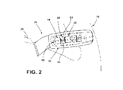
[0009] FIG. 2 is a perspective view of an aspect of a selection
assembly in the form of a
stalk that is mounted to a steering column of a vehicle;
[0010] FIG. 3 is a schematic cross-sectional view of the selection
assembly of FIG. 2,
taken along line III-Ill;
[0011] FIG. 4 is a perspective view of an aspect of a selection
assembly in the form of a
stalk that is mounted to a steering column of a vehicle;
CA 03212239 2023- 9- 14
WO 2022/208228
PCT/I132022/052567
3
[0012] FIG. 5 is a schematic cross-sectional view of the selection
assembly of FIG. 2,
taken along line V-V;
[0013] FIG. 6 is a perspective view of an aspect of a selection
assembly in the form of a
stalk that is mounted to a steering column of a vehicle;
[0014] FIG. 7 is a schematic cross-sectional view of the selection
assembly of FIG. 2,
taken along line VII-VII;
[0015] FIG. S is a schematic perspective view of an aspect of a
selection assembly and
showing operation of the selection assembly in a first direction;
[0016] FIG. 9 is a schematic perspective view of the selection assembly
of FIG. 8 and
showing operation of the selection assembly in a second direction; and
[0017] FIG. 10 is a schematic perspective view of the selection
assembly of FIG. 8 and
showing operation of the selection assembly through a plurality of selection
positions.
DETAILED DESCRIPTION OF THE PREFERRED EMBODIMENTS
[0018] As required, detailed embodiments of the present disclosure are
disclosed herein;
however, it is to be understood that the disclosed embodiments are merely
exemplary of
the invention that may be embodied in various and alternative forms. The
figures are not
necessarily to a detailed design; some schematics may be exaggerated or
minimized to
show function overview. Therefore, specific structural and functional details
disclosed
herein are not to be interpreted as limiting, but merely as a representative
basis for
teaching one skilled in the art to variously employ the present invention.
[0019] For purposes of description herein, the terms "upper," "lower,"
"right," "left,"
"rear," "front," "vertical," "horizontal," and derivatives thereof shall
relate to the
concepts as oriented in FIG. 1. However, it is to be understood that the
concepts may
assume various alternative orientations, except where expressly specified to
the
contrary. It is also to be understood that the specific devices and processes
illustrated in
the attached drawings, and described in the following specification are simply
exemplary
embodiments of the inventive concepts defined in the appended claims. Hence,
specific
dimensions and other physical characteristics relating to the embodiments
disclosed
herein are not to be considered as limiting, unless the claims expressly state
otherwise.
CA 03212239 2023- 9- 14
WO 2022/208228
PCT/IB2022/052567
4
[0020] The present illustrated embodiments reside primarily in
combinations of method
steps and apparatus components related to a selection assembly for modifying
the drive
train 24 of a vehicle. Accordingly, the apparatus components and method steps
have
been represented, where appropriate, by conventional symbols in the drawings,
showing
only those specific details that are pertinent to understanding the
embodiments of the
present disclosure so as not to obscure the disclosure with details that will
be readily
apparent to those of ordinary skill in the art having the benefit of the
description herein.
Further, like numerals in the description and drawings represent like
elements.
[0021] As used herein, the term "and/or," when used in a list of two or
more items,
means that any one of the listed items can be employed by itself, or any
combination of
two or more of the listed items, can be employed. For example, if a
composition is
described as containing components A, B, and/or C, the composition can contain
A alone;
B alone; C alone; A and B in combination; A and C in combination; B and C in
combination; or A, B, and C in combination.
[0022] In this document, relational terms, such as first and second,
top and bottom, and
the like, are used solely to distinguish one entity or action from another
entity or action,
without necessarily requiring or implying any actual such relationship or
order between
such entities or actions. The terms "comprises," "comprising," or any other
variation
thereof, are intended to cover a non-exclusive inclusion, such that a process,
method,
article, or apparatus that comprises a list of elements does not include only
those
elements but may include other elements not expressly listed or inherent to
such
process, method, article, or apparatus. An element proceeded by "comprises ...
a" does
not, without more constraints, preclude the existence of additional identical
elements in
the process, method, article, or apparatus that comprises the element.
[0023] As used herein, the term "about" means that amounts, sizes,
formulations,
parameters, and other quantities and characteristics are not and need not be
exact, but
may be approximate and/or larger or smaller, as desired, reflecting
tolerances,
conversion factors, rounding off, measurement error and the like, and other
factors
known to those of skill in the art. When the term "about" is used in
describing a value or
an end-point of a range, the disclosure should be understood to include the
specific value
or end-point referred to. Whether or not a numerical value or end-point of a
range in the
CA 03212239 2023- 9- 14
WO 2022/208228
PCT/IB2022/052567
specification recites "about," the numerical value or end-point of a range is
intended to
include two embodiments: one modified by "about," and one not modified by
"about." It
will be further understood that the end-points of each of the ranges are
significant both
in relation to the other end-point, and independently of the other end-point.
[0024] The terms "substantial," "substantially," and variations thereof
as used herein
are intended to note that a described feature is equal or approximately equal
to a value
or description. For example, a "substantially planar" surface is intended to
denote a
surface that is planar or approximately planar. Moreover, "substantially" is
intended to
denote that two values are equal or approximately equal. In some embodiments,
"substantially" may denote values within about 10% of each other, such as
within about
5% of each other, or within about 2% of each other.
[0025] As used herein the terms "the," "a," or "an," mean "at least
one," and should not
be limited to "only one" unless explicitly indicated to the contrary. Thus,
for example,
reference to "a component" includes embodiments having two or more such
components unless the context clearly indicates otherwise.
[0026] Referring now to FIGS. 1-10, reference numeral 10 generally
refers to a selection
assembly that is incorporated within a passenger compartment 12 of a vehicle
14 and
typically near a driver's seat 16 for the vehicle 14. The selection assembly
10 is used for
modifying various settings for one or more devices that are incorporated
within a vehicle
14. In certain aspects, these settings are related to a vehicle transmission
or vehicle
differential and include a first transmission setting, a second transmission
setting and a
third transmission setting. It is contemplated that the first transmission
setting can
include a two-wheel drive setting 18, the second transmission setting can
include a four-
wheel drive high-speed setting 20, and the third transmission setting can
include a four-
wheel drive low-speed setting 22. Operation of the selection assembly 10 in
this regard
modifies the drive train 24 to operate between these various settings for
operating the
vehicle 14.
[0027] According to various aspects of the device, the selection
assembly 10 operates a
drive train 24 or other components of a vehicle transmission and includes a
primary
interface 26, such as a stalk, a shifter, rotary dial 90, or other similar
interface member,
that is operable in at least two directions of operative movement. Generally,
these
CA 03212239 2023- 9- 14
WO 2022/208228
PCT/IB2022/052567
6
directions of movement are oblique with respect to one another. In certain
aspects of
the device, these directions of movement are perpendicular or normal with
respect to
one another. These directions of movement can include up and down with respect
to
the steering column 28 as well as back and forth in a generally axial
direction with
respect to the steering column 28.
[0028] Referring again to FIGS 1-10, a built-in user interface 30 is
incorporated within the
primary interface 26 and includes a selector 32 of the selection assembly 10
that is
operable relative to the primary interface 26. The operative movement of the
selector
32 is operable along a primary movement path 34 that can be used to select
between the
two-wheel drive setting 18 and the four-wheel drive high-speed setting 20.
Additionally,
operative movement of the selector 32 includes a secondary movement path 36
that
deviates from the primary movement path 34. The combination of the primary
movement path 34 and the secondary movement path 36 can be operated
contemporaneously to operate the user interface 30 for selecting between the
four-
wheel drive high-speed setting 20 and the four-wheel drive low-speed setting
22. The
secondary movement path 36 operates the selector 32 between a ready state 150
and an
activated state 152. In the ready state 150, the selector 32 is able to be
manipulated
between the two-wheel drive setting 18 and the four-wheel drive high-speed
setting 20.
In the activated state 152, the selector 32 is moved along the secondary
movement path
36 and is able to be manipulated between the four-wheel drive high-speed
setting 20 and
the four-wheel drive low-speed setting 22.
[0029] Referring now to FIGS. 2 and 3, the user interface 30 that is
incorporated within
the primary interface 26 includes a slider 50 that is laterally operable
relative to various
surface indicia 52 of the primary interface 26. These indicia correspond to at
least the
two-wheel drive setting 18, the four-wheel drive high-speed setting 20 and the
four-
wheel drive low-speed setting 22. In this configuration, the slider 50 can be
moved
laterally along the primary movement path 34 between the two-wheel drive
setting 18
and the four-wheel drive high-speed setting 20. When movement is desired
between the
four-wheel drive high-speed setting 20 and the four-wheel drive low-speed
setting 22,
the slider 50 can be pushed downward or otherwise depressed along the
secondary
movement path 36 and then slidably operated along the primary movement path
34.
CA 03212239 2023- 9- 14
WO 2022/208228
PCT/IB2022/052567
7
This combined movement of the primary movement path 34 and the secondary
movement path 36 serves to operate the slider 50 between the four-wheel drive
high-
speed setting 20 and the four-wheel drive low-speed setting 22.
[0030] According to various aspects of the device, as disclosed herein,
operation of the
selector 32 between the two-wheel drive setting 18 and the four-wheel drive
high-speed
setting 20 can be performed frequently and at various speeds and conditions
that the
vehicle 14 is operating under. In addition, operation of the drive train 24
and other
portions of the transmission between the two-wheel drive setting 18 and the
four-wheel
drive high-speed setting 20 typically engages and disengages various splines
and similar
linkages that are included within the drive train 24. Again, the engagement
and
disengagement of these splines can be performed at a wide range of speeds and
operating conditions of the vehicle 14.
[0031] Where the drive train 24 is being moved between the four-wheel
drive high-
speed setting 20 and the four-wheel drive low-speed setting 22, gear ratios
within the
transmission are being operated such that shifting the drive train 24 between
the four-
wheel drive high-speed setting 20 and the four-wheel drive low-speed setting
22, while
moving at a high rate of speed, is typically not desirable. Accordingly,
movement of the
selector 32 along the secondary movement path 36 can be used as a failsafe or
blocking
feature 70 for preventing operation of the drive train 24 to the four-wheel
drive low-
speed setting 22 when conditions of the vehicle 14 are not optimal for such
modification.
In this configuration, where a user desires to move the slider 50 between the
four-wheel
drive high-speed setting 20 and the four-wheel drive low-speed setting 22,
movement of
the slider 50 in the secondary movement path 36 may result in a blocking
feature 70 of
the user interface 30 to prevent movement of the slider 50 along the primary
movement
path 34 and toward the four-wheel drive low-speed setting 22. The blocking
feature 70
can include an operable interface mechanism that physically and/or
electromagnetically
prevents the slider 50 or other aspect of the selector 32 from operating along
the
secondary movement path 36. In the case of an electromagnetic actuator, the
blocking
feature 70 can be a physical member that is operated through an
electromagnetic or
electromechanical mechanism.
CA 03212239 2023- 9- 14
WO 2022/208228
PCT/IB2022/052567
8
[0032] According to the various aspects of the device, the blocking
feature 70 can be
coupled with a controller that activates and deactivates the blocking feature
70 based
upon the performance of one or more protocols related to the status of the
vehicle 14.
These protocols can be a predefined set of vehicular protocols. By way of
example and
not limitation, the slider 50 can be activated to move from the four-wheel
drive high-
speed setting 20 to the four-wheel drive low-speed setting 22, and vice versa,
when the
vehicle 14 is stopped or traveling below a predetermined velocity. These
protocols can
also be related to an orientation of the vehicle 14. In such an aspect of the
device, the
blocking feature 70 may be unable to move from the four-wheel drive low-speed
setting
22 and back to the four-wheel drive high-speed setting 20 when the vehicle 14
is in a
slope having an incline that is above a certain threshold. In the various
aspects of the
device, where the designated protocols are met, the blocking feature 70 can be
activated
or deactivated to prevent or allow, respectively, operation of the slider SO
between
various positions, such as the four-wheel drive high-speed setting 20 and the
four-wheel
drive low-speed setting 22.
[0033] Referring now to FIGS. 4 and 5, the primary interface 26 can
include the user
interface 30 that incorporates a rotary member 80 that operates about a
rotational axis
82 of the primary interface 26 between the two-wheel drive setting 18 and the
four-
wheel drive high-speed setting 20. The user interface 30 can also include a
button 84
that is operable through the secondary movement path 36 that can be used in
combination with the rotary portion of the primary interface 26 to move the
primary
interface 26 between the four-wheel drive high-speed setting 20 and the four-
wheel
drive low-speed setting 22. The button 84 can be located on the rotary member
80 or
can be positioned on a separate portion of the primary interface 26 that is
stationary
with respect to the rotary member 80.
[0034] As exemplified in FIG. 5, the button 84 incorporated within the
selection assembly
operates along the secondary movement path 36 and in a direction that deviates
from
the primary movement path 34. In the illustrated aspect of the device, the
primary
movement path 34 is rotational about the rotational axis 82. Conversely, the
secondary
movement path 36 is in a radial direction relative to the rotational axis 82.
It is
contemplated that the secondary movement path 36 can also be an axial motion
with
CA 03212239 2023- 9- 14
WO 2022/208228
PCT/IB2022/052567
9
respect to the rotational axis 82. Operation of the button 84 along the
secondary
movement path 36 can serve to engage a blocking feature 70 that can prevent
movement of the rotary portion of the selection assembly 10 from moving to the
four-
wheel drive low-speed setting 22 until such time as conditions or protocols
related to the
vehicle 14 are met for such modification.
[0035] In various aspects of the device, the selection assembly 10, as
shown in FIGS 4 and
5, can include more than one button 84. In such an aspect of the device, each
button 84
can have a dedicated secondary movement path 36 that corresponds to a
dedicated
operation of the selection assembly. Additionally, the direction, distance or
magnitude
of the secondary movement paths 36 for the buttons 84 can be different. Each
button 84
can include a dedicated blocking feature 70 as well as dedicated protocols
that must be
met to activate and deactivate the respective button 84 of the selection
assembly. By
way of example and not limitation, one of the buttons 84 can be used to
operate the
transmission between the four-wheel drive high-speed setting 20 and the four-
wheel
drive low-speed setting 22. The other of the buttons 84 can be used for some
other
operation, such as a park lock, placing the transmission in a manual shift
condition, or
some other operational configuration.
[0036] Referring now to FIGS. 6 and 7, the selection assembly 10 can
include a rotary dial
90 that can be rotated in a rotary motion about a rotational axis 82 to
operate the
selection assembly 10 between the two-wheel drive setting 18 and the four-
wheel drive
high-speed setting 20. Where the user desires to manipulate the drive train 24
between
the four-wheel drive high-speed setting 20 and the four-wheel drive low-speed
setting
22, the rotary dial 90 can be pressed inward in a generally lateral motion and
into the
primary interface 26 or otherwise depressed or deflected into the primary
interface 26.
This lateral motion defines a deflected secondary position of the selector 32
that moves
the rotary dial 90 and the rotational axis 82. This lateral motion of the
rotary dial 90
allows for rotation of the rotary dial 90 toward the four-wheel drive low-
speed setting
22. In this aspect of the device, the primary movement path 34 is a rotation
of the rotary
dial 90 about the rotational axis 82. The secondary movement path 36 is a
generally
linear or radial deflection of the rotary dial 90 that also moves the
rotational axis 82 of
the rotary dial 90 in a generally linear or lateral motion.
CA 03212239 2023- 9- 14
WO 2022/208228
PCT/1132022/052567
[0037] Referring again to FIGS. 2-7, manipulation of the selector 32
along the primary
movement path 34 serves to operate the drive train 24 to engage and disengage
various
splines for moving the drive train 24 between the two-wheel drive setting 18
and the
four-wheel drive high-speed setting 20. Manipulation of the selector 32 in the
secondary
movement path 36 serves to activate a gear-ratio component of the drive train
24 that is
used to manipulate the drive train 24 between the four-wheel drive high-speed
setting
and the four-wheel drive low-speed setting 22. Accordingly, manipulation of
the
selector 32 through the primary movement path 34 and the secondary movement
path
36 serves to operate both of these assemblies contemporaneously to shift the
gear ratio
setting of the drive train 24 for operating the vehicle 14. As discussed
herein,
manipulation of the drive train 24 between the two-wheel drive setting 18 and
the four-
wheel drive high-speed setting 20 operates to engage and disengage a four-
wheel drive
linkage without changing the gear ratios for operating the vehicle 14.
[0038] As exemplified in FIGS. 1-7, wherein the primary interface 26 is
in the form of a
stalk, positioning of the selector 32 of the user interface 30 within the
stalk attached to
the steering column 28 provides convenient access to the user for manipulating
the
setting of the drive train 24 for the vehicle 14. In this configuration, the
user can quickly
manipulate the selector 32 of the user interface 30 without moving their hands
far from
the steering wheel for the vehicle 14.
[0039] As discussed herein, operation of the selector 32 can be used to
prevent
inadvertent adjustment of the selector 32 between the four-wheel drive high-
speed
setting 20 and the four-wheel drive low-speed setting 22. The requirement for
moving
the selector 32 through the primary movement path 34 as well as the secondary
movement path 36 typically requires a deliberate operation of the user
interface 30.
Accordingly, inadvertent or accidental manipulation of the selector 32 into
the four-
wheel drive low-speed setting 22 can be prevented.
[0040] As discussed herein, operation of the selector 32 can include
the primary
movement path 34 and the secondary movement path 36 that deviate from one
another.
These movements can be perpendicular with respect to one another, as generally
illustrated in FIG. 2. As exemplified in FIGS. 3 and 4, the primary movement
path 34 can
be an arcuate motion around a particular rotational axis 82. The secondary
movement
CA 03212239 2023- 9- 14
WO 2022/208228
PCT/1B2022/052567
11
path 36 can be a radial motion or linear motion that operates toward and away
from the
rotational axis 82 of the selector 32. It is contemplated that other
combinations of
movements can be utilized to operate the primary movement path 34 and
secondary
movement path 36, where these movement paths deviate from one another to
require
the composite movements for moving the drive train 24 between the four-wheel
drive
high-speed setting 20 and four-wheel drive low-speed setting 22.
[0041] Referring now to FIGS. 8-10, the primary interface 26 is
operable relative to the
steering column 28 in multiple directions. The use of the multi-direction
operation of the
primary interface 26 can be used to provide shifting functions for a gear
selector 100 as
well as the selection assembly 10 for the drive train 24. The gear selector
100 can be
utilized when the primary interface 26 is moved in a first direction 140, such
as toward
the user. Using the gear selector 100, the user can modify the transmission
between a
plurality of gear settings. The gear settings can include drive 102, neutral
104 and
reverse 106. In some aspects of the device, a park setting 108 can also be
included. By
operating the primary interface 26 in a second direction 142, typically a
direction that
opposes the gear selector 100, the user can switch the functionality of the
primary
interface 26 from the gear selector 100 and the selection interface 144 for
the drive train
24. The primary interface 26, in a rest position 110, lies between the gear
selector 100
and the selection interface 144.
[0042] Referring again to FIGS. 8-10, when the user operates the
primary interface 26 in
the first direction 140 relative to the steering column 28, the primary
interface 26 can be
operated from a central position 120 that is indicative of neutral 104 and
between an
upper position 122 and a lower position 124 that are indicative of drive 102
and reverse
106, respectively. When the primary interface 26 is moved in the second
direction 142 to
engage the selection assembly 10, the primary interface 26 can be moved
between the
central position 120 that is indicative of the two-wheel drive setting 18, and
between an
upper position 122 and lower position 124 that are indicative of the four-
wheel drive
high-speed setting 20 and the four-wheel drive low-speed setting 22,
respectively. To
move the primary interface 26 into the four-wheel drive low-speed setting 22,
it is
contemplated that a separate blocking feature 70 can be incorporated within
the primary
interface 26, to ensure that an intentional movement is used to move the
primary
CA 03212239 2023- 9- 14
WO 2022/208228
PCT/IB2022/052567
12
interface 26 into the two-wheel drive setting 18. Using the blocking feature
70, the
primary interface 26 can be conveniently manipulated between the two-wheel
drive
setting 18 and the four-wheel drive high-speed setting 20 by moving the
primary
interface 26 between the upper position 122 and the central position 120.
These
movements can be accomplished without inadvertently moving the primary
interface 26
into the lower position 124 that is indicative of the four-wheel drive low-
speed setting
22, without first disengaging the blocking feature 70 of the selection
assembly 10.
[0043] According to the various aspects of the device described herein,
it is
contemplated that the selection assembly 10 can include a dedicated park
interface 130
that is used to engage the park setting 108, as well as a park lock for
maintaining the
vehicle 14 in a parked position when desired. This feature can be used to both
engage
and disengage the park setting 108 when needed for parking the vehicle 14 or
for
preparing the vehicle 14 to be operated.
[0044] According to the various aspects of the device, the selection
assembly 10 can be
incorporated in any one of various stalk configurations. These configurations
can include
a turn-signal stalk, a gear shift stalk, a wiper stalk and others. It is also
contemplated that
the selection assembly 10 can be incorporated into a dedicated stalk that is
used to
modify the gear train.
[0045] It is to be understood that variations and modifications can be
made on
the aforementioned structure without departing from the concepts of the
present
invention, and further it is to be understood that such concepts are intended
to be
covered by the following claims unless these claims by their language
expressly state
otherwise.
CA 03212239 2023- 9- 14