Note: Descriptions are shown in the official language in which they were submitted.
WO 2022/211709 1
PCT/SE2022/050306
A steel for an overlay welding material
A steel for overlay welding material suitable for structural components used
in contact with
liquid lead or liquid lead alloys in nuclear reactors.
Alumina forming steels like FeCrAl are often superior to chromia forming
stainless steels
concerning oxidation and corrosion in many high temperature environments.
FeCrAl-steels
have weak high temperature mechanical properties but can be used as weld
overlay on load
bearing steels. However, it has been shown that a welded FeCrAl structure is
not ductile and
can easily crack upon welding or cooling. This is a serious problem that
cannot be
circumvented when a construction must follow a pressure vessel code and/or a
bend test code.
Theoretically, one solution could be to use a high aluminum alloyed austcnitic
steels or nickel
base alloy as weld overlay (or as a mono material) but that would be very
expensive and it
would not work in certain environments that demand quite low nickel content,
such as liquid
lead or lead-bismuth eutectic (LBE) environments.
The current invention has a cost-effective solution to this problem. By using
a modified and
lean AFA (Alumina Forming Austenite) composition it is possible to produce a
ductile and
corrosion resistant weld overlay. By using the inventive weld overlay on a
standard stainless
steel that is accepted for pressure vessels as a substrate, it is possible to
solve severe high
temperature corrosion problems.
AFA-compositions have been promising as corrosion and creep resistant steels
for more than
10 years but have not reached the market due to formability and ageing
problems under
certain circumstances. Both issues are connected to loss of ductility.
W020167039679A1 discloses an AFA alloy suitable for use in contact with liquid
lead.
Ever since the early works carried out at the Oak Ridge National Laboratory
(ORNL), the
presence of Nb has been reported as a necessity for alumina formation in AFA
steels and high
amounts of austenite stabilizing elements, preferably Ni but also Cu and Mn
has been added
in addition to Ni in order to obtain a single phase stable and highly uniform
austenitic
microstructure, avoiding a ferritic-austenitic dual phase structure. A review
of earlier work on
AFA alloys has been given by K.R: Larsen in Materials Performance, 54(9):30-
34. The
content of which is available under the following links:
https://www.researchgate.net/publication/283690362 Alumina-
forming austenitic alloys resist high-temperature corrosion
CA 03213279 2023- 9- 25
WO 2022/211709 2
PCT/SE2022/050306
and
http://www.materialsperformance.com/articles/material-selection-
design/2015/12/alumina-
forming-austenitic-alloy s-resist-high-temperature-corrosion
In the section "Fine-Tuning the Alloy Composition- three requirements for AFA
alloys are
listed. Firstly, the presence of 12 to 15 % Cr and 2.5 to 4 % Al. Secondly,
the addition of 0.6
to 3 % Nb and thirdly, that the amounts of N, Ti and V generally must be
minimized.
The present inventors have surprisingly found that it is possible to produced
AFA-alloys
having good properties for use in contact with liquid lead or lead based
alloys even if one
does not adhere to all three requirements set out above.
The current invention uses a fine-tuned lean AFA-composition in which the
content of Cr can
be less than 12% and wherein Nb need not be deliberately added, provided that
the alloy
comprises 0.1-1.0 % Ti. It has also been found that a certain amount of
ferrite not only can he
tolerated but that the dual phase structure may have a positive influence on
the properties.
However, the amount of ferrite should be restricted to 5 to 25 vol. %. A
preferred amount is
10-25 vol. % ferrite in the welded structure. This gives important benefits in
terms of
improved weldability (avoid hot cracking) and improved corrosion resistance
(increased Al-
diffusion) with maintained ductility during long term ageing.
A "conventional" AFA-steel with 98-100% austenite and with a composition close
to this
invention are more prone to metal dissolution in liquid lead and have less
oxidation resistance
in steam.
However, the ferrite content should not exceed 25 vol. % in order to avoid a
continuous
network of ferrite and thereby a reduced ductility and secondary brittle
phases as well as to
avoid liquid metal embrittlement (LME) in liquid lead and lead bismuth
eutectic (LBE)
alloys.
This inventive welding consumable/weld overlay could be applied on several
components in a
lead cooled reactor, such as the inner side of the vessel, pump components,
steam generator
components, core barrel and other components in the core structure where
corrosion
protection with kept ductility is required.
The oxidation resistance exceeds the conventional stainless steels like AIST
316L by far,
especially in liquid lead/LBE but also in steam.
CA 03213279 2023- 9- 25
WO 2022/211709 3
PCT/SE2022/050306
The inventive lean welding consumable/weld overlay have the unique combination
of good
welding-, casting-, corrosion-, erosion- and high temperature mechanical
properties as well as
LME-resistance with maintained ductility and cost competitiveness.
The welding consumable can be either wire or strip and the welding methods may
be TIG,
MIG, Laser welding or weld overlay processes used in heavy industry including
different Arc
Welding technologies, SAW (with wire or strip), SMAW(with wire), GMAW(with
wire),
FCAW(with wire) and electro slag welding, ESW, (with strip).
The most important feature of the invention being that the weld overlay
qualifies according to
the requirements in pressure vessel codes for standard bend test concerning
corrosion
protective surface layers.
BRIEF DESCRIPTION OF THE DRAWINGS
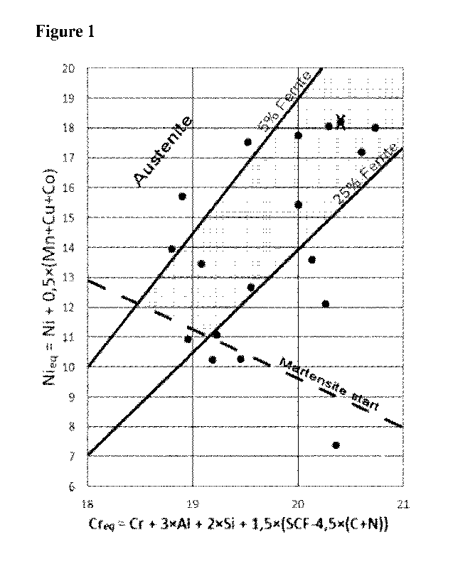
Figure 1. Schaeffler diagram for AFA-steels 5-25% ferrite is marked in grey.
The last term in the Cr-equivalent is the sum of all Strong Carbide Formers
(SCF) such as Ti,
Nb, Ta, V and Zr, in a free non-carbide/nitride form, i.e. with the amount of
carbon and
nitrogen subtracted.
Figure 2. Example of the welded structure of the inventive steel marked with
an X in Figure
1. Typical welded structure of the inventive alloy with 17% ferrite and 87 %
austenite.
Figure 3. Electron microscope (SEM) cross-section of the inventive steel as
weld overlay on
AISI 316L base metal (substrate) exposed in liquid lead at 700 C. The
inventive steel
consumable is marked with an X in Figure 1. The top surface (weld) with
residual lead has
formed a protective oxide.
Figure 4. Same cross-section as in Figure 3 but in higher magnification. The
inventive weld
overlay has formed a fully protective aluminium rich oxide underneath the
original weld
oxide. The aluminium content measured by EDX (not shown here) indicate up to
10 weight-
% aluminium at the inner protective oxide layer, i.e. the real Al-content is
much higher since
the layer is only around one micrometre thick.
Figure 5. SEM-micrograph showing the inventive steel in as cast condition
exposed to steam
for 700h @ 700 C. Polished cross-section and exposed surface which was grinded
with SiC-
paper 600# before exposure. Thin protective Al-rich oxide with no visible
corrosion attack.
CA 03213279 2023- 9- 25
WO 2022/211709 4
PCT/SE2022/050306
Figure 6. SEM-micrograph showing the commercial AISI 316L steel exposed to
lead for 700h
@ 700 C. Polished cross-section and exposed surface. Severe corrosion with
nickel
dissolution, lead penetration (light grey in contrast) and internal oxidation
(dark in contrast),
especially in the grain boundaries.
Figure 7. SEM-micrograph showing the commercial AISI 316L steel exposed to
steam for
700h @ 700 C. Polished cross-section. Severe oxidation, up to 100 micrometre
in depth.
Figure 8. Example of bend test of weld overlay based on the inventive steel on
a AISI 316L
substrate.
DETAILED DESCRIPTION
The importance of the separate elements and their interaction with each other
as well as the
limitations of the chemical ingredients of the claimed alloy are briefly
explained in the
following. All percentages for the chemical composition of the steel are given
in weight %
(wt. %) throughout the description. Upper and lower limits of the individual
elements can be
freely combined within the limits set out in the claims.
9.0-12.0 % Chromium is to be present in a content of at least 9 % to provide a
good
oxidation and corrosion resistance. Cr is a ferrite stabilizing element, which
reacts with
carbon to form carbides. Cr also favours protective alumina scale formation by
the so-called
"third-element effect". However, the chromium content should not exceed 12 %
since the
amount of ferrite in the weld must be minimized to maximum 25 %.
Too much ferrite in the weld makes it less ductile and it may fail standard
bend tests and
formation of undesired brittle phases increases during ageing at lower
temperatures, i.e., 400
¨ 600 C. The chromium content is therefore limited to 12 %. The lower limit
may be 9.0 %
9.5 %, 10.0 %, 10.5 % or 11.0 %. The upper limit may be 11%, 11.5 % or 12.0 %
10-16.8 % Nickel is an austenite stabilizer and its primary purpose is to
stabilize the
austenitic phase. To get a ductile welded structure it is important to keep
the amount of ferrite
lower than 25 %, thus the Ni content should be higher than 10%. To reach a
balanced
structure with optimised corrosion properties, the nickel content should not
be higher than
16.8 %. Especially the risk for nickel dissolution corrosion in the weld
increases sharply in
liquid lead/LBE if the nickel content exceeds 16.8 %.
CA 03213279 2023- 9- 25
WO 2022/211709 5
PCT/SE2022/050306
The lower limit may therefore be 10.0%, 10,5% or 11.0 % and the upper limit
may be 12.0 %,
12.5 %, 13.0 %, 13.5 % 14.0 %, 14.5 %, 15.0 %, 15.5 %, 16.0, or 16.5 %.
2.0-3.4 Aluminum is essential for the formation of the Al-rich oxides and is
therefore added
in an amount of 2.0 - 3.4 %. However, too much Al may result in the formation
of undesired
brittle phases. Aluminium stabilizes ferrite and must be balanced with
austenite stabilizers to
avoid too much ferrite. The lower limit may therefore be 2.1 %, 2.2 %, 2.3 or
2.4 % and the
upper limit may be 3.1 %, 3.2 % or 3.3 %.
Carbon is always present in steels, it forms carbides and stabilizes the
austenite. C. i.e.
carbides, are also important to minimize the grain growth upon cooling from
melting
temperatures in the weld. The upper limit for carbon may be set 0.09 %, 0.08
%, 0.07 %, 0.06
% or 0.05%. The lower limit may be as low as 0.02 % depending on the boron and
nitrogen
contents.
Nitrogen may be present in the steel in an amount of < 0.06 % because N reacts
with Al. N
may also form precipitates with Nb, Ti, Zr, V and Y and is beneficial for
strength and creep
resistance.
Molybdenum and Tungsten increases the high temperature mechanical properties
and are
carbide forming elements and also strong ferrite formers and may result in the
formation of
brittle Laves phase. Addition of W and Mo increases the creep properties. The
amount of
molybdenum and tungsten should each be restricted to maximum 1.5 %, preferably
to 1 % or
less. The lower limit may each be 0.001, 0.005, 0.01, 0.05, 01 0.1 %. If the
alloy composition
is prone to lave phase precipitation and ferrite formation, the higher limit
may be 0.5 % or 0.1
%.
Niobium is an element that form carbides, nitrides and carbo-nitrides and is
beneficial for
strength and creep resistance. In addition, Nb tends to improve the oxidation
resistance in the
same way as RE (Reactive Element). Nb need not be added but may be present, in
an amount
of up to 0.5 %. Preferably, the upper limit may be set to 0.4 % 0.3 %, 0.2 %,
0.1 % 01 0.05%.
The lower limit may be 0.001, 0.005, 0.01, 0.05, or 0.1 %.
Tantalum form carbides, nitrides and carbo-nitrides and is beneficial for
strength and creep
resistance. In addition, Ta tends to improve the oxidation resistance in the
same way as RE
(Reactive Element). Ta is therefore present, individually, in an amount of up
to 1.5 %. The
lower limit may be 0.001, 0.005, 0.01, 0.05, or 0.1 %.
CA 03213279 2023- 9- 25
WO 2022/211709 6
PCT/SE2022/050306
Titanium
Ti is deliberately added to the present alloy in an amount of 0.1 ¨ 1%,
preferably 0.2 ¨ 0.9%,
more preferably 0.3-0.9%. Ti favours the formation of a stable alumina layer
and act as a
grain refiner.
Zr
Is a reactive element that promote formation of a protective alumina scale.
Strong carbide
formers and strong oxide particles formers, beneficial for high temperature
mechanical
properties. The amount of Zr may be up to 0.5 %. If higher, hot ductility may
be negatively
affected. The upper limit may further be restricted 0.4, 0.3. 0.2, or 0.1%.
The lower limit may
be 0.01%.
Hf
Is a reactive element that promote formation of a protective alumina scale.
Strong carbide
formers and strong oxide particles formers, beneficial for high temperature
mechanical
properties. The amount of Hf may be up to 0.5 %. The upper limit may further
be restricted
0.4, 0.3. 0.2, or 0.1%. In nuclear applications the amount of hafnium is
preferably lower than
0.01 %.
Yttrium
Reactive elements that promote formation of a protective alumina scale. It may
be included in
carbides and nitrides. It is a strong oxide particle former, beneficial for
high temperature
mechanical properties.
The amount of Y may be up to 0.5 %. The upper limit may be < 0.3 % since
higher amount
may induce hot-cracking in austenite. The upper limit may further beet to 0.2
%, 0.1 %, 0.055
or 0.03 %. If added, the lower limit may be 0.001, 0.01, 0.05. or 0.1 %.
Silicon is beneficial for high temperature oxidation properties but stabilizes
ferrite and forms
brittle phases and in higher content and should thus be limited. The upper
limit is 1.6 % and
may be set to 1.2 %, 1.0 %, 0.9 %, 0.8%, 0.5 % or 0.3 %. The lower limit may
be set to 0.2 %,
0.3% or 0.4 %.
Manganese
Austenite stabilizer and may to some extent replace Ni. Mn is present in an
amount of 1.5 to
3.0 %. Mn also improves the mechanical properties to some extent. Mn is
included in
carbides as well as oxides. Mn tends to promote secondary phases, such as
sigma phase,
CA 03213279 2023- 9- 25
WO 2022/211709 7
PCT/SE2022/050306
which may cause embrittlement. The oxidation properties may be affected
negatively at
higher concentrations. The upper limit may be 3 %, 2.9 %, 2.8 %, 2.7 % or 2.6
%. The lower
limit may be 15 %, 1.6%, 1.7%, 1.8%, 1.9%, 2.0 %2.1%, 2.2 %, 2.3 % or 2.4 %.
However,
according to a conceivable alternative, Mn need not be deliberately added
provided that the
requirements CrEq = 18.5-21 and NiEg = 11-20 are fulfilled.
Copper is an optional element, which has an austenite stabilizing effect, but
it may form
brittle phases, especially under irradiation. It is not possible to extract
copper from the steel
once it has been added. This drastically makes the scrap handling more
difficult. For this
reason, copper is normally limited to 1.7 %, preferably < 1 %.
If added, the lower limit may be 0.1, 0.2, 0.3, 0.4, or 0.5 %. The upper limit
may be 1.7 %,
1.5%, 1.3%, or 1%.
Cobalt
The Co-content should be as low as possible in nuclear applications but for
other application
it is beneficial in stabilizing an austenitic structure and improves the
strength at all
temperatures. In compositions aimed for nuclear applications, the amount is
preferably < 0.1
%. In compositions where Co is deliberately added, the amount may be < 1 %.
Vanadium forms carbides and carbonitrides of the type M(C,N) and Z-phase in
the matrix of
the steel. However, the V amount should be < 0.5 %. The lower limit may be
0.01, 0.05, 0.1,
or 0.15%.
Sulphur
Sulphur should not deliberately be added, lowers the oxidation properties.
Boron
Boron may act as a substitution to carbon but is also a strong neutron
absorber. Boron may
increase the creep strength in marten sitic steels by reducing the coarsening
of carbides at
higher temperatures. Boron suppresses the nucleation of ferrite on austenitic
grain boundaries.
The amount of B may be < 0.1 %, but preferably < 0.01 % depending on the
carbon content.
Bi, Se
These elements may be added to the steel in the claimed amounts in order to
further improve
the machinability, hot workability and/or weldability. Maximum amount of each
element is
preferably less than 0.1 %, more preferably less than 0.02%. Preferably
neither is deliberately
added since they may impair corrosion resistance.
CA 03213279 2023- 9- 25
WO 2022/211709 8
PCT/SE2022/050306
Ca, Mg
These elements may be added to the steel in the claimed amounts in order to
further improve
the machinability, hot workability and/or weldability. Maximum amount of each
element is
preferably less than 0.1 %, more preferably less than 0.02%.
Oxygen
0 is not deliberately added. The amount of 0 is preferably less than 0.05%.
RE (Reactive elements) Improves the oxide scale properties and are beneficial
for high
temperature mechanical properties. RE as used in this application embraces the
elements with
atomic numbers 21 and 57-71 because Yttrium is defined separately. The amount
of RE may
be < 0.2 %. The lower limit may be 0.001, 0.005, 0.01, 0.05, or 0.1 %. For
instance,
Lanthanum may be added in the range of 0.001 - 0.2 %, or 0.01 -0.1 %.
The steel preferably having 5-25 volume-% ferrite and structure in a matrix of
austenite. A
specialized Schaeffler diagram for AFA-steels and the inventive welding
consumable
compositions has been constructed based on experimental data. The composition
ranges in
terms of Cr and Ni equivalents (CrEq ; NiEq) for the inventive welding
consumable shown in
Figure 1.
Preferably the Cr and Ni equivalents (CrEil ; NiEq) fulfils:
CrEq = 18.5-21 and NiEg = 11-20 wherein CrEq = Cr + 3A1+ 2Si +
1.51(Ti+Nb+V+Ta+Zr) -
4.5(C+N)] and NiEq= Ni + 0.5(Mn+Cu+Co).
This inventive steel can be used as weld overlay on preferably austenitic
substrate materials
such as MST 316L and Alloy 800HT.
An example of the inventive weld overlay structure on a 316L substrate is
shown in Figure 2.
The amount of delta-ferrite is 17% in this example, which improves the
weldability without
compromising the inherent austenitic phase immunity to Liquid Metal
Embrittlement (LME).
As previously mentioned, the preferred amount of delta-ferrite in the final
weld overlay
structure is 5-25%. The upper limit of delta-ferrite may further be restricted
to 23%, 21%,
CA 03213279 2023- 9- 25
WO 2022/211709 9
PCT/SE2022/050306
19%, 17% or 15%. The lower limit may further be restricted to 6%, 7%, 8%, 9%.
or 10%. A
preferred range may be 10-20 %.
Then amount of intermetallic phases are preferably less than 5 vol%,
preferably less than 1 %,
most preferably the steel is void of intermetallic phases. Examples of
intermetallic phases are
sigma, laves, and chi.
APPLICATIONS
The steel can be used as weld overlay material in a nuclear reactor or in
concentrated solar
power plant. In particular, a nuclear reactor or a concentrated solar power
plant that is cooled
by a lead or lead-bismuth alloy. In such applications the molten lead or lead-
bismuth alloy
may have a temperature of < 600 C and/or an oxygen content of at least 10-7
wt.%.
A nuclear pressure vessel may comprise the steel.
The steel can be in the form of a strip or a wire and can be used as a welding
consumable
and/or a weld overlay material.
A compound material can be formed by a substrate of stainless steel on to
which the inventive
steel defined above is provided by overlay welding. The substrate material can
be a steel
selected form the group ATST 316, ATST 316L, ATST 316 LN, ALLOY 800 or ALLOY
800HT.
Preferably, the weld overlay comprises 5 to 25 vol. % ferrite, more preferably
10 to 20 vol. %
ferrite.
EXAMPLES
In the present examples, the invention, both as welding consumable and weld
overlay are
compared with the commercial stainless steel, AIST 316L.
The eleven inventive steel compositions disclosed in Table la were selected
from a larger
experimental steel matrix of 42 different compositions. All steels were casted
in a high
frequency induction furnace, approximately 100 g per batch. The twelve
selected steels were
cast directly into 3,5 mm thin rectangular plates, approximately 200 x 20 mm.
Small samples
of as cast material (approx. 30x 4x3,5 mm3) were cut out for corrosion and
erosion tests.
CA 03213279 2023- 9- 25
WO 2022/211709 10
PCT/SE2022/050306
The plates were cut by wire discharge machining (WEDM) into 200 mm long
ribbons, 3,5 x
1,5 mm in cross-section, which was used as welding consumables. A 4 mm thick
plate made
of stainless AISI 316L was used as substrate for the different weld overlays.
Manual TIG
welding 100A DC was used.
The compositions of the selected alloys are shown in
Table la. The corresponding chromium equivalents (Creq) and nickel equivalents
(Nieq) are
disclosed in Table lb.
Table la. Elemental compositions of the 11 best alloys (1-11) concerning
weldability,
corrosion properties and ductility. All values are given in wt-%. AISI 316L is
the substrate
material for the weld overlay tests. All welded samples contain approximately
5-25% delta-
ferrite.
Alloy Al Cr Ni C
N Mn Cu Si Ti V Nb Mo/VV/Ta Other
AISI
316L 17 10 0,02 1 0,4 0,5 Mo=2
1 2,4 11,8 16,3 0,037 0,006 2,5 1 0,32 0,63
0,001 0,001 La=0,015
2 3 9 11,5 0,07
0,006 2,3 0,01 0,65 0,35 0,16 0,049 Zr=0,04
3 2,9 10 12,4 0,07 0,07 2,1 0,01 0,29 0,36 0,19 0,035
Zr=0,02
4 2,9 10,2 14,3 0,072 0,003 2,2 0,01 0,37 0,37 0,21 0,028
Zr=0,05
5 2,6 10,3 16,7 0,05 0,004 2,1 0,01 0,83 0,3 0,2 0,034
B=0,012
6 3,2 10,2 15,7 0,07 0,008 2,3 0,7 0,3 0,3 0,15 0,04
La=0,022
7 2,5 11,2 16,2 0,038 0,009 2,6 1 0,26 0,81
0,006 0,001 Y=0,012
Y=0,01
8 2,6 11,8 16,2 0,036 0,009 2,6 0,95 0,26 0,2 0,006 0,001
Mo=0,7 Z=0,02
9 2,6 11,9 16,2 0,044 0,009 2,6 0,98 0,26 0,2 0,006 0,001
W=0,94 Y=0,014
10 2,5 11 16,2 0,052 0,009 2,6 1,1 0,26 0,2 0,006 0,001
Ta=0,9 Y=0,09
11 2,6 11,6 16,4 0,046 0,006 2,6 0,96 0,14 0,63 0,084 0,22
Zr=0,03
CA 03213279 2023- 9- 25
WO 2022/211709 11
PCT/SE2022/050306
Table lb. Cr- and Ni- equivalents optimised for lean AFA's with small amounts
of delta
ferrite. Creq = Cr + 3A1 +2Si + 1,5(SCF-4,5(C+N)). SCF are the sum of strong
carbide
formers such as Ti, Nb, Ta, V, and Zr. Nieq = Ni + 0,5(Mn + Cu + Co), all
values in weight-
%.
Alloy Cr-eq Ni-eq
1 20,3 18,1
2 19,6 12,7
3 19,2 13,5
4 20,0 15,4
20,1 17,8
6 20,7 17,2
7 20,1 18,0
8 20,1 18,0
9 20,2 18,0
18,9 18,1
11 20,7 18,2
The cast samples were grindcd and polished to remove any initial oxides using
Strucrs
abrasive SiC paper (final step #500) and finally cleaned in ethanol and
deionised H/0. The
weld overlay samples were exposed as welded with remaining weld oxides.
The corrosion experiment was conducted in a COSTA (COrrosion Test Stand for
liquid metal
10 Alloys) setup, constructed by Karlsruhe Institute of Technology
(KIT). Samples were fitted
into alumina crucibles using alumina holders as support and then filled with
lead. All
crucibles were subsequently placed on nickel trays and placed inside the
sealed quartz tubes
of the furnace. More information on the COSTA setup is presented in J. Nucl.
Mater.
278(2000) 85-95.
Two environmental conditions were chosen, using lead as liquid metal as one
condition and
the other exposure using steam. The oxygen concentration in the liquid lead
was controlled by
means a gas mixture containing Ar, H2 and H20. The H2/H20 ratio was set to
approximately
10-3, which corresponds to 10-5 weight-% oxygen dissolved in the lead at the
exposure
temperature, 700 C. The exposure time was 700h. A Z1ROX SGM5 oxygen analyser
was
used to monitor the oxygen partial pressure at the systems gas outlet. The
steam exposure was
CA 03213279 2023- 9- 25
WO 2022/211709 12
PCT/SE2022/050306
as well performed at 700 C for 700h. Inert Ar-gas was added to stabilise the
gas flow in the
furnace during the steam exposure. After exposure, cross sections were
prepared by polishing
one side with approximately a 450 of each sample to a final step of #4000. The
samples were
then cleaned with ethanol and deionised H20, followed with drying using
pressurized air.
Representative example of results from the liquid lead and steam exposures can
be seen in
Figure 3-7 and a summary of the results is sown in Table 2. All as cast and
polished samples
behaved as god as or better than the welded overlay of the same material which
is expected
since the weld overlay is slightly diluted or mixed with the AISI 316L-base
material, typically
5-10%, measured on the top of the weld overlay.
Table 2. Summary of the result from liquid lead and steam exposures @ 700 C.
Liquid Lead Steam
Alloy P.O I.O. P.O. I.O.
AISI 316L No 60 gm No 90 gm
Inventive
Yes No Yes No
steels
P.O.- Protective oxide, 1Ø-Internal Oxidation/Corrosion.
All weld overlay samples on AIS1 316L-substrate passed the bend test without
any signs of
crack initiation, one example of such test sample is shown in Figure 8. The
three-point bend
test radius was smaller than required by the ASME bend test code and the bend-
test angle was
larger than required, i.e., larger than 180'.
CA 03213279 2023- 9- 25