Note: Descriptions are shown in the official language in which they were submitted.
WO 2022/207316 - 1 -
PCT/EP2022/056789
System, implant unit and method for the treatment of head and facial pain
Technical Field
The disclosed subject matter described hereafter refers to a system and a
method for electrical
nerve stimulation. Furthermore, reference is made to a use of the method for
electrical nerve
stimulation in the treatment of head and facial pain.
Background
Neural modulation, i.e. electrical stimulation of nerves, presents the
opportunity to treat many
physiological conditions and disorders by interacting with the body's own
natural neural pro-
cesses. Neural stimulation includes inhibition (e.g. blockage), modulation,
modification, regula-
tion, or therapeutic alteration of activity, electrical or chemical, in the
central, peripheral, or auto-
nomic nervous system.
By modulating the activity of the nervous system, for example through the
stimulation of nerves
or the blockage of nerve signals, several different goals may be achieved.
Motor neurons may be
stimulated at appropriate times to cause muscle contractions. Sensory neurons
may be blocked,
for instance to relieve pain, or stimulated, for instance to provide a signal
to a subject. In other
CA 03213321 2023- 9- 25
WO 2022/207316 - 2 -
PCT/EP2022/056789
examples, modulation of the autonomic nervous system may be used to adjust
various involuntary
physiological parameters, such as heart rate and blood pressure. Neural
modulation may provide
the opportunity to treat several diseases or physiological conditions, a few
examples of which are
described in detail below.
For the purpose of this disclosure, the terms "stimulation" and "modulation"
are used interchange-
ably if nothing else is specified.
Typically, neural stimulators deliver therapy in the form of electrical pulses
and include two or
more electrode in a proximity of the target location, such as a specific nerve
or section thereof.
Electrical stimulation is adjustable through various parameters, such as the
polarity of elec-
trode(s), voltage or current amplitudes, pulse frequency, pulse width,
configuration and selection
of electrodes and others, as these define the electrical stimulation therapy
to be delivered to the
user in need of therapy. Such parameters may be preprogrammed or programmable
to deliver
the desired stimulation and result desired from the stimulation therapy.
Among the conditions to which neural stimulation may be applied, is the
occurrence of migraine
headaches. Conventional treatments typically involve the use of analgesics of
varying strengths.
However, due to neural involvement in the sensation of pain, methods and
apparatuses aimed at
neural stimulation may offer a different solution. Pain sensation in the head
is transmitted to the
brain via afferent or sensory neurons. Such neurons may include the greater
occipital nerve, the
lesser occipital nerve, the third occipital nerve and the trigeminal nerve.
When a subject experi-
ences head and facial pain, such as during a migraine headache, the inhibition
of these nerves
may serve to decrease or eliminate the sensation of pain.
Neural stimulation may also be an effective solution to other conditions, for
example, cluster head-
aches, or even sleep disordered breathing and hypertension. The foregoing are
just a few exam-
ples of conditions to which neuromodulation may be of benefit, however
embodiments of the in-
vention described hereafter are not necessarily limited to treating only the
above-described con-
ditions.
Prior Art
Known implantable systems for neuromodulation are usually made up of three
parts: a lead, a
rechargeable or non-rechargeable implantable pulse generator, and extensions
to connect the
pulse generator and the lead. These extensions are required for the delivery
of electrical stimula-
tion to the occipital nerves, as the pulse generator is implanted in the
abdomen or in the flank.
CA 03213321 2023- 9- 25
WO 2022/207316 - 3 -
PCT/EP2022/056789
However, this technology has several disadvantages. For example, it leads to
insufficient cover-
age of pain area in some patients. In addition, implantation of such large
devices requires a long
and invasive surgical procedure. Another drawback comes from the fact that the
excess need for
tunneling and extension leads to possible infection, dislocation, lead
breakage and erosion risks.
Lastly, the non-rechargeable implanted pulse generator creates the need for
revision with the
consequence of a higher revision rate and higher cost.
Summary of the Disclosed Subject-matter
One of the objectives of the present disclosure is to respond to the
disadvantages of the prior art
and to provide an improved system for electrical nerve stimulation. In
particular, a system should
be provided that allows for a simple and time-efficient implantation
procedure, improving the re-
sults by new technology and implant technique and avoiding the burdens of
existing technologies.
According to one aspect of the disclosure, a neurostimulation system for
treating head and facial
pain is provided, the system comprising an implant unit configured for
implantation inside a sub-
ject's body; an external unit configured for a location external to the
subject's body; wherein the
external unit comprises: a processor, a power source and a primary
transmission unit in electrical
communication with the power source and the processor; wherein the implant
unit comprises: at
least one lead, at least one pair of modulation electrodes attached to the at
least one lead, and a
secondary transmission unit in electrical communication with the at least one
lead and its elec-
tronics; and wherein the processor of the external unit is configured to
establish a coupling be-
tween the primary transmission unit and the secondary transmission unit and to
transmit power
from the power source to the implant unit via said coupling.
The implant unit may preferably comprise only basic circuitry in order to
perform the desired neu-
rostimulation tasks. Advantageously, this leads to the implant unit not
requiring its own energy or
power reservoir embedded in its housing. Instead, power supply may for example
be achieved
via an inductive transcutaneous radiofrequency link (RF) between the external
unit and the im-
plant unit or between the physician programmer and the implant unit by direct
RF transmission
(i.e. BLE ¨ Bluetooth Low Energy). According to further embodiments, the
implant unit may com-
prise, enclosed in a sealed housing, one or more of the following: a secondary
transmission unit
or antenna for receiving and/or sending one or more signals from an external
primary transmission
unit; an AC/DC converter; a CPU or a memory (e.g. a very low power
microcontroller); at least on
current source; a stimulation lead comprising at least one modulation
electrode; a programmable
stimulation profile look-up table; a bootloader embedded software; an analog
multiplexer to con-
figure the modulation electrodes connected to the voltage or current source.
CA 03213321 2023- 9- 25
WO 2022/207316 - 4 -
PCT/EP2022/056789
Amongst the preferred functions of the presented implant unit may be the
following: run neu-
rostimulation therapy according to a stimulation profile stored in the lookup
table; regularly run
diagnostics of both the patient and the implant unit on; send data or updates
on the patient's
and/or the implant unit's status to an external unit when an inductive
transmission channel be-
tween the implant unit and the external is established.
Preferably, the external unit is rectangular-, circular- or oval-shaped and
may be attached to an
external carrier. In an even more preferred embodiment, the external unit is
ergonomically de-
signed to fit behind a subject's ear. The external unit may further comprise a
housing, wherein
the housing can contain the processor, the primary transmission unit and the
power source. Ex-
amples for the external unit include patches, buttons, ear pieces or other
receptacles. In one
embodiment, for example, the housing of the external unit may include a
flexible material such
that the external unit may be configured to conform to a desired location.
According to certain
embodiments, the external unit may, encapsulated in a housing, further
comprise one or more of
the following: a primary transmission unit or antenna for receiving from
and/or sending to the
internal secondary transmission unit one or more inducing signals; an DC/AC
converter; a power
source; a CPU or a memory (e.g. a microcontroller); a bicolor LED (e.g. for
emitting red and/or
green light); a vibrator module for giving feedback to the patient in case the
primary and secondary
antennae are aligned with each other; a demodulator receiving implant unit
status as well as alerts
and warnings sent from the implant unit; a push button.
Amongst the preferred functions of the external unit may be the following:
provide power to supply
the implant unit via inductive coupling; recharge the battery located in the
external unit when
placed on a charging unit; receive data from the implant unit when an
inductive transmission
channel between the implant unit and the external is established; transfer
said data to a charging
unit; power a bicolor LED; etc.
In a preferred embodiment, the primary transmission unit may be a coil
antenna. The coil may be
made from any suitable conductive material and may be configured to include
any suitable ar-
rangement of conductive coils (diameter, number of coils, layout of coils,
etc.). A coil suitable for
use as primary transmission unit may have a diameter of about 0,5 cm to 10 cm,
and may be
circular-shaped, rectangular-shaped or oval-shaped. In some embodiments, the
coil antenna may
have a diameter of about 0,5 cm to 2,5 cm. A coil antenna suitable for use as
primary transmission
unit may have any number of windings. Further, a coil antenna suitable for use
as primary trans-
mission unit may have a wire diameter of about 0.1 mm to 2 mm. According to
another embodi-
ment, the transmission unit can be a printed circuit board antenna or it can
be directly printed on
the housing of the external unit.
CA 03213321 2023- 9- 25
WO 2022/207316 - 5 -
PCT/EP2022/056789
The external carrier may be configured for attachment to the subject's skin.
For example, the
carrier may be a flexible skin patch configured for adherence to the subject's
skin, e.g. through
adhesives or mechanical means. It is also possible to attach the external unit
to the subject's skin
via a magnetic force, wherein the external carrier comprises a magnetic
dipole, with a respective
opposite dipole located just beneath the subject's skin. In this case, the
opposite dipole may pref-
erably be part of the implant unit. Further means of attachment can include a
hook-and-loop fas-
tener based system (e.g. Velcro ) or an ear-loop based system, which would
require no skin
adhesive patch. The external carrier may be flexible or rigid, or may have
flexible portions and
rigid portions. The external carrier and/or the housing of the external unit
may further be con-
structed of any suitable material. In particular, the external carrier or the
housing may include a
flexible material such that the external unit may be configured to conform to
a desired location.
The material of the flexible substrate may include, but is not limited to,
plastic, silicone, woven
natural fibers, and other suitable polymers, copolymers, and combinations
thereof. According to
a preferred embodiment of the invention, the design of the external carrier
may allow the skin to
"breathe", e.g. by being at least partially air-permeable. Further, the
external carrier may comprise
a soft material, Any portion of external unit may be flexible or rigid,
depending on the requirements
of a particular application. The external unit may be configured to be affixed
to the subject. For
example, for a subject suffering from head and facial pain, the external unit
may be attached
behind the subject's ear at the level of the mastoid process.. Suitable
locations for the external
unit may be determined by communication between external unit and the implant
unit. Addition-
ally, the external unit may generate a signal that provides the subject with
feedback regarding the
optimal position of the external unit. The optimal position may for example be
measured based
on a feedback from the implantable unit to the external unit. Once a desired
position is detected,
a vibrator module located in the external unit may give a vibration signal
indicating correct align-
ment of the internal unit with the external unit.
Furthermore, the carrier may include a connector for selectively or removably
connecting the
housing, the connector extending or protruding from the external carrier to be
received by a recess
of the housing. Alternatively, the housing can comprise a connector to be
received by a recess of
the external carrier. Preferably, the external carrier will be a mechanically
flexible rectangular- or
circular-shaped patch that will suit placement in the curved area behind the
ear of the subject.
According to an additional embodiment, the system may further comprise a
physician external
unit and a physician programming unit. The physician external unit may for
example be normal
external unit in the sense of this disclosure, having a specialized software
installed on it, wherein
the specialized software is dedicated to be used by the physician. The
physician programming
unit may be an external computing unit, e.g. a PC or a similar handheld or
portable device like a
tablet or a smartphone. Together, the physician external unit and the
physician programming unit
CA 03213321 2023- 9- 25
WO 2022/207316 - 6 -
PCT/EP2022/056789
may be configured to prepare a therapy template and store the configuration
under specific
names. Furthermore, the physician programming unit may serve for secure
identification of the
implant unit and establish a secure pairing between the implant unit and the
physician external
unit. Further functions of the physician external unit and the physician
programming unit may
comprise: Verifying patient history log files stored in the implant unit;
prepare/load a therapy and
run a test stimulation sequence during patient visits; program the tested
therapy during patient
visits; receive a status report from the implant unit (e.g. impedance of the
electrodes, alerts or
warnings, history log files, etc.) during the patient visits; provide a user-
friendly interface to visu-
alize the therapy before programming (e.g. show electrode configuration,
current amplitudes,
pulse durations, ON-OFF period, etc.) It is understood the data transfer
between the physician
external unit and the implant unit may be carried in real-time.
The modulation electrodes may further be configured to cause, when supplied
with the modulation
signal, a unidirectional and/or a bidirectional electrical field. For this
purpose, the modulation elec-
trodes may be made from conductive and biocompatible materials, such as
stainless steel, gold,
platinum, iridium, platinum-iridium, platinum-gold, conductive polymers, etc.
In particular, the elec-
trodes may be configured to facilitate, when supplied with the modulation
signal, a substantially
unidirectional and/or bidirectional electric field sufficient to modulate the
occipital nerve. Further-
more, the modulation electrodes may include anode and cathode electrode pairs,
which may be
spaced apart by about a distance of about 0.2 mm to 20 mm. Other
configurations, like tripolar
electrodes (e.g. + - +), may be used, as well. Furthermore, monopolar
electrode systems may be
used, wherein the housing of the implantable unit comprises a (large)
indifferent electrode. The
implant may also comprise electronic components like a switch matrix to select
the configuration.
The external unit may be configured to communicate with the implant unit. A
circuitry of the ex-
ternal unit may, for example, be configured to generate an electric primary
signal on the primary
transmission unit that may cause an electric secondary signal on the secondary
transmission unit
in the implant unit. In certain embodiments, however, it may be advantageous
(e.g. in order to
generate a unidirectional electric field for modulation of a nerve) to provide
a temporary or con-
tinuous DC (Direct Current) field inducing signal at the modulation
electrodes. Additionally, a com-
bination of AC and DC signals may be implemented with the system of this
disclosure. To convert
the AC secondary signal on the secondary transmission unit to a DC field
inducing signal, the
implant unit may include a signal modifier, for example, a demodulator or an
AC-DC converter.
The AC to DC converter may include any suitable converter known to those
skilled in the art. For
example, in some embodiments the AC-DC converter may include rectification
circuit components
including, for example, diodes and appropriate capacitors and resistors. In
alternative embodi-
ments, the implant unit may include an AC-AC converter, or no converter, in
order to provide an
AC field inducing signal at modulation electrodes.
CA 03213321 2023- 9- 25
WO 2022/207316 - 7 -
PCT/EP2022/056789
As noted above, the secondary signal may be configured to generate an electric
field between
the modulation electrodes. In some instances, the magnitude, orientation,
energy density, and/or
duration of the generated electric field resulting from the secondary signal
on the secondary trans-
mission unit may cause current flow sufficient to modulate one or more nerves
in the vicinity of
the electrodes. In such cases, the secondary signal may be referred to as a
modulation signal,
and the associated primary signal may be referred to as a modulation control
signal. In other
instances, the magnitude and/or duration of the field inducing signal may
generate an electric field
that does not result in nerve modulation. In such cases, the field inducing
signal may be referred
to as a sub-modulation signal.
In some instances, the magnitude and/or duration of the generated electric
field resulting from the
field inducing signal may be sufficient to modulate one or more nerves in the
vicinity of the mod-
ulation electrodes. In such cases, the field inducing signal may be referred
to as a modulation
signal. In other instances, the magnitude and/or duration of the field
inducing signal may generate
an electric field that does not result in nerve modulation_ In such cases, the
field inducing signal
may be referred to as a sub-modulation signal. Various types of field inducing
signals may con-
stitute modulation signals. For example, in some embodiments, a modulation
signal may include
a moderate amplitude and moderate duration, while in other embodiments, a
modulation signal
may include a higher amplitude and a shorter duration. Various amplitudes
and/or durations of
field-inducing signals across electrodes may result in modulation signals, and
whether a field-
inducing signal rises to the level of a modulation signal can depend on many
factors (e.g. distance
from a particular nerve to be stimulated; whether the nerve is branched;
orientation of the induced
electric field with respect to the nerve; type of tissue present between the
electrodes and the
nerve; etc.).
According to another embodiment, the power source may be permanently or
removably coupled
to a location within the external unit. The power source may further include
any suitable source
of power configured to be in electrical communication with the processor. For
example, the power
source may include a rechargeable and/or replaceable battery, such as a paper
battery, thin film
battery or other type of battery. In some embodiments, the power source may
include a substan-
tially flat, flexible battery. The power source may provide power for the
system, in particular for
stimulation. In many embodiments, since the size of the external unit must be
as small as possi-
ble, the total size of the external unit will be determined by the size of the
power source, e.g. the
battery. Preferably, the power source has an area that is smaller than or
equal to 500 mm2.
According to a preferred embodiment, the system includes a charging unit
configured for charging
the power source of the external unit. For example, it can be intended to
recharge the power
CA 03213321 2023- 9- 25
WO 2022/207316 - 8 -
PCT/EP2022/056789
source of the external unit during daytime. The charging unit may comprise one
or more of the
following: a wire connector (e.g. a USB-Type connector) for power supply; a
transmission unit or
antenna for establishing an inductive link to recharge the external unit; a
CPU or a memory (e.g.
a microcontroller); a local area network or internet interface (e.g. a Wi-Fi-
interface) configured for
connection to a webserver; at least one LED; a 4G module configured for
transferring information
to a webserver.
Amongst the preferred functions of the external unit may be the following:
recharge the recharge-
able battery of the external unit; display the battery status of the external
unit on a display or
similar user interface; drive one or more LEDs signaling charging process;
drive a LED signaling
receipt of an alert; send data stored on the external unit and sent by the
implant unit to a web-
server using local area network or internet interface (e.g. a \M-Fi-
interface); etc.
The circuitry of the implant unit, i.e. the modulation electrodes, the
electronics, the antenna and
connecting wires, may include conductive and/or biocompatible materials, such
gold, platinum,
iridium, platinum-iridium, platinum-gold, conductive polymers, etc.
Preferably, the implanted unit
is substantially manufactured in one piece, using only one material (e.g.
silicone), with the excep-
tion of the electronic components (i.e. electrodes, wires, transmission units,
insulators etc.). Al-
ternatively, a biological glue may be used to join the stimulation bridge and
the transmission unit
together.
According to another preferred embodiment, it is also possible that the lead
comprises a flexible
carrier, wherein the secondary transmission unit and the at least one lead are
each connected to
the flexible carrier sized and configured for implantation beneath the skin.
In that case, the lead
comprising the modulation electrodes may also be referred to as stimulation
bridge. The second-
ary transmission unit may be mounted onto or otherwise be integrated with the
flexible carrier.
Further, the secondary transmission unit may include a coil antenna. Such a
coil antenna may be
made from any suitable conductive material and may be configured to include
any suitable ar-
rangement of conductive coils (diameter, number of coils, layout of coils,
etc.). A coil antenna
suitable for use as secondary transmission unit may have a diameter of about
0.5 cm to 5 cm,
and may be circular-, rectangular- or oval-shaped. A coil antenna suitable for
use as secondary
transmission unit may have any number of windings. Further, a coil antenna
suitable for use as
secondary transmission unit may have a wire diameter of about 0.1 mm to 2 mm.
According to
another embodiment, the transmission unit can be a printed circuit board
antenna.
In some embodiments, the flexible carrier of the implant comprises a flexible,
biocompatible, ma-
terial and/or an insulating material. Such materials may include, for example,
silicone, phenyltri-
CA 03213321 2023- 9- 25
WO 2022/207316 - 9 -
PCT/EP2022/056789
methoxysilane (PTMS), polymethyl methacrylate (PMMA), Parylene C, polyimide,
liquid polyi-
mide, laminated polyimide, black epoxy, polyether ether ketone (PEEK), Liquid
Crystal Polymer
(LOP), Kapton, etc. Further to the above, the implant may be encapsulated in
at least one layer
of a biocompatible material, and may include ceramic material, thermoplastic
material such as
ULTEM, or other compatible materials.
Since the implant unit does not comprise a power source (e.g. in form of a
battery), it can be kept
small. Thus, it can be implanted through a short and minimally invasive
procedure. In particular,
a system according to this disclosure may be implanted in a one-day hospital
setting that should
not last more than 30 minutes. The flexible carrier may also be fabricated
with a thickness suitable
for implantation under a patient's skin. For example, the implant unit may
have thickness of less
than 4 mm, in particular of less than about 2 mm. In a preferred embodiment,
the implant is con-
figured for implantation through a 3 cm incision in the subject's skin at the
level of the mastoid
process.
In addition to the above, the modulation electrodes may be located alongside
the at least one
lead. The lead comprises modulation electrodes and may preferably be
configured for implanta-
tion in the vicinity of one or more nerves to be modulated such that the
electrodes are spaced
apart from one another along a longitudinal direction of a number nerves. It
may be beneficial if
one of the modulation electrodes is located at one of the lead's ends. For
example, modulation
electrodes may be spaced apart by a distance of about 1 mm to 20 mm, or
between 5 mm and
mm. In a preferred embodiment, the at least one lead may comprise eight
modulation elec-
trodes evenly spaced along the lead ("octopolar lead"). The electrodes may
further be configured
to facilitate an electric field in response to an applied electric signal, the
electric field including
field lines extending in the longitudinal direction of the nerve to be
modulated.
The at least one lead and the modulation electrodes may form a stimulation
bridge. A stimulation
bridge according to this embodiment has an elongated shape. Preferably, the
length of the stim-
ulation bridge is at least 20 times the width or diameter of the stimulation
bridge. According to an
even preferred embodiment, the length of the stimulation bridge is at least 50
times the width or
diameter of the stimulation bridge. For example, the lead may have a diameter
of 1-3 mm and a
length of up to 100 mm. Once implanted, the at least one stimulation bridge
may be located in
such a way inside the subject's body that it is directed towards a point of
about 1 to 1.5 cm above
the subject's inion. Preferably, the at least one stimulation bridge comprises
a modulation elec-
trode at the end of the lead that has a maximum distance from the secondary
transmission unit.
The stimulation bridge may in particular be configured for implantation in
such a way that at least
one modulation electrode is located along the lead close to the secondary
transmission unit, which
may be mounted on the flexible carrier. The secondary transmission unit may
then be located in
CA 03213321 2023- 9- 25
WO 2022/207316 - 10 -
PCT/EP2022/056789
the vicinity of the C2 vertebra, as this is the link of the trigeminal
cervical complex and the dorsal
root ganglion of 02. The precise location of the secondary transmission unit
of the implant unit
also determines the position of the external unit when attached to the
subject's skin.
With a stimulation bridge as described herein, it is possible to precisely
innervate or stimulate a
single nerve, as opposed to only being able to stimulate a greater neural
area. Obviously, the
latter is still possible in addition to single nerve stimulation by means of
the stimulation bridge as
described.
Preferably, the lead of the stimulation bridge is oval-, rectangular- or lens-
shaped when viewed
in a transversal cross-section, wherein the electrodes are only disposed on
the side of the lead
that is facing the nerve to be stimulated. This way, the stimulation signal
can be focused in a
much more precise manner, which in tune is more energy-efficient. A
stimulation bridge having
an oval or lens-shape when viewed in a cross-section has the additional
advantage that its
rounded "edges" may lead to a higher comfort for the subject or patient once
implanted.
According to a preferred embodiment, the lead or the stimulation bridge may be
configured for
bilateral stimulation or for unilateral stimulation, wherein unilateral
stimulation comprises a short
lead and bilateral stimulation comprises a long lead. For example, it may be
intended that the
short lead (unilateral stimulation) is shorter than 10 cm or about 10 cm of
length, whereas the
long lead (bilateral stimulation) is longer than 10 cm. A stimulation bridge
configured for bilateral
stimulation may for example comprise a total of 16 electrodes (i.e. two
distinct sections each
comprising 8 modulation electrodes)
Further, bilateral stimulation requires two incisions, one small (3 cm)
incision at the level of the
mastoid process and a second one 1 to 1.5 cm above the inion for implantation
of the stimulation
bridge. However, according to a preferred embodiment, only one channel will be
required for both
forms of stimulation (unilateral and bilateral). With a stimulation bridge
having a lead that is longer
than 10 cm, i.e. that is configured for bilateral stimulation, it is possible
to stimulate a larger neural
area of the subject with only to minor incisions. Thus, the medical procedure
of implanting the
implant unit can be kept relatively short and still allow for a very efficient
neural stimulation.
The processor may comprise programmable electronics and be configured to cause
transmission
of a modulation signal from the primary transmission unit to the secondary
transmission unit of
the implant unit implanted beneath the skin of the subject, i.e. beneath the
subcutaneous tissue.
The processor may be further configured to adjust one or more characteristics
of the modulation
signal to generate a sub-modulation control signal adapted to cause a current
at the at least
modulation electrode below a neuronal modulation threshold of the occipital
nerve when received
CA 03213321 2023- 9- 25
WO 2022/207316 - 11 -
PCT/EP2022/056789
by the secondary transmission unit of the implant unit and to generate the
modulation signal
adapted to cause a current at the modulation electrode above a neuronal
modulation threshold
of the occipital nerve when received by the secondary transmission unit of the
implant unit. This
way, the external unit can generate a magnetic field by radiofrequency, which
in turn generates
stimulation of the occipital nerve field through the modulation electrodes of
implant unit. Thus,
there is no longer a need for having an implant pulse generator (IPG)
implanted deep in the
muscle or to make loops, excess tunneling or to add extensions all the way
down to the IPG,
which can take much time during the respective implantation procedure.
Preferably, the distance
between the external unit and the (implanted) implant unit is less than 5 cm,
in particular less than
1 cm.
According to certain embodiment, the processor may be programmable to cause
transmission of
a modulation signal from the primary transmission unit to the secondary
transmission unit of the
implant unit based on distinct pre-programmed modulation protocols (including
one or more
"modes"). For example, a "night mode" protocol may be provided, the protocol
including:
- decreasing the voltage or current amplitude of the modulation signal in a
specific range
or percentage;
- adding OFF periods to the duty cycle
- switching to a "burst mode" instead of a "tonic mode".
Burst stimulation typically delivers groups of pulses at a higher frequency
and at amplitudes much
lower than tonic stimulation and is considered non-detectable by a patient and
thus well indicated
overnight. This way, effective stimulation can be maintained during the sleep
of a patient, without
being interruptive or otherwise uncomfortable.
The at least one processor may include any electric circuit that may be
configured to perform a
logic operation on at least one input variable. The at least one processor may
therefore include
one or more integrated circuits, microchips, nnicrocontrollers, and
microprocessors, a digital signal
processor (DSP), a field programmable gate array (FPGA).
According to a further embodiment, the external unit may comprise a storage
unit in electrical
connection with the processor, configured to store stimulation data and. Such
data can comprise
any form physiological parameter of the subject, e.g. feedback of the subject
and stimulation pa-
rameter. This way, the processor can perform predictive stimulation control on
based on patient
feedback, i.e. based on the stored physiological parameters.
Further, the external unit may comprise an energy harvesting unit configured
for deriving energy
from an external source. The external source may be solar power, thermal power
(e.g. in the form
of the subject's body heat), kinetic energy (due to movement of the subject)
or the like. The energy
CA 03213321 2023- 9- 25
WO 2022/207316 - 12 -
PCT/EP2022/056789
harvesting unit may further be connected to the power source of the external
unit, thereby re-
charging said power source.
As part of a preferred embodiment, the implant unit may comprise tines or
spikes for fixation of
the at least one lead to a tissue of the subject. This way, dislocation of the
implant unit from the
tissue can be avoided, which would otherwise occur due to neck movements of
the subject. The
tines can be disposed on the flexible carrier and/or on the at least one lead
of the implant unit and
may preferably be made from a biocompatible material. According to another
embodiment, fixa-
tion of the main body of the implant unit may comprise meshes. It is also
possible that RX markers
are placed along the lead to verify correct placement during the surgery
procedure by use of an
RX machine and a screen for the lead and RX markers visualization.
It is further possible that the implant unit is configured implantation in a
substantial hairless region
of the head to optimize the communication between external and internal unit.
Modulation of the
occipital nerves, such as the greater, lesser and third occipital nerve, and
secondary the trigemino
cervical complex will be possible through the stimulation bridge and will be
useful for treating head
and facial pain, such as that from migraines. It may be intended not to
stimulate deep brain struc-
tures and spinal cord. The neurostimulation may instead be focused on chronic
migraine (CM)
and chronic cluster headache (CCH), refractory to pharmacological treatments.
For those pa-
tients, especially for CCH, there is still an unmet medical need.
The system further may comprise a remote control configured for adjustment of
the neurostimu-
lation. The remote control enables the subject to self-adjust the electrical
stimulation of the re-
spective nerve. This is especially useful for patients with chronic migraine
and chronic cluster
headache (CCH), which require continuous stimulation. In certain embodiments,
the remote con-
trol can be in the form of a dedicated software ("App") to be installed on a
computer or on any
suitable handheld device (e.g. on a mobile phone or on a tablet).
The coupling between the secondary transmission unit of the implant unit and
the primary trans-
mission unit of the external unit can comprise capacitive coupling, inductive
coupling, ultrasound,
light and/or radiofrequency coupling. In particular, such coupling of the
primary transmission unit
and the secondary transmission unit may include any interaction between the
primary transmis-
sion unit and the secondary transmission unit that causes a signal on the
secondary transmission
unit in response to a signal applied to the primary transmission unit, wherein
each signal may
comprise power and/or data. In some embodiments, coupling between the primary
and secondary
transmission units may include capacitive coupling, inductive coupling,
radiofrequency coupling,
etc. and any combination thereof. As a result of coupling between the primary
transmission unit
and the secondary transmission unit, a secondary signal may arise on the
secondary transmission
CA 03213321 2023- 9- 25
WO 2022/207316 - 13 -
PCT/EP2022/056789
unit when the primary signal is present on the primary transmission unit. Such
coupling may in-
clude inductive/magnetic coupling, RF coupling/transmission, capacitive
coupling, or any other
mechanism where a secondary signal may be generated on the secondary
transmission unit in
response to a primary signal generated on the primary transmission unit.
According to another embodiment, the implant unit may comprise a processor in
addition to the
processor comprised by the external unit. The processor of the implant unit
may then be referred
to as internal processor. When implemented, the internal processor may
comprise at least one
software program installed on it. Thus, the internal processor may be
configured to run and diag-
nose stimulation therapy and send alerts and warnings (A&VV) to the external
unit in case the
implant unit encounters problems.
As a preferred embodiment, a system for treating head and facial pain could
comprise the external
unit be attached to the external carrier which is attached to a patient's
skin. This "patient external
unit" may establish, via its primary transmission unit, a transmission link
with the implant unit
implanted beneath the subject's skin. Furthermore, the external unit may
supply power to the
implant unit via induction. The implant unit may then be configured to
communicate with the ex-
ternal unit via wireless transmission and may further comprise a bootloader
which starts a soft-
ware program installed on the internal processor of the implant unit. Lastly,
the implant unit may
be configured to run and diagnose stimulation therapy and send alerts and
warnings (A&VV) to
the external unit in case the implant unit encounters problems. The system may
further comprise
a charging unit for charging the "patient external unit" via inductive
coupling. However, the charg-
ing unit may further be configured to collect A&W data stored on the external
unit and sent to the
external unit from the implant unit. Furthermore, the charging unit may
comprise a charger LED
and an emergency LED, which can be turned on or off. For example, the charger
LED may be
turned on for as long as the external unit is being charged by the charging
unit. Likewise, the
emergency LED may be turned on when the charging unit receives A&W data from
the external
unit. Additionally, the charging unit may connect to a web server and upload a
log file and an
A&W report (if present).
Additionally, the preferred system may comprise a physician programming unit
connectable to
the external unit. When the external unit is connected to the physician
programming unit, it may
also be referred to as "physician external unit". The "physician external
unit" may be the same
device as the "patient external unit" or it may be a different external device
used solely by the
physician. The physician programming unit may be an external computing unit,
e.g. a PC or a
similar handheld or portable device like a tablet or a smartphone. Together,
the physician external
unit and the physician programming unit may be configured to prepare a therapy
template and
store the configuration under specific names. Furthermore, the physician
programming unit may
CA 03213321 2023- 9- 25
WO 2022/207316 - 14 -
PCT/EP2022/056789
serve for secure identification of the implant unit and establish a secure
pairing between the im-
plant unit and the physician external unit. Further functions of the physician
programming unit and
the physician programming unit may comprise: Verifying patient history log
files stored in the
implant unit; prepare/load a therapy and run a test stimulation sequence
during patient visits;
program the tested therapy during patient visits; receive a status report from
the implant unit (e.g.
alerts or warnings, history log files, etc.) during the patient visits;
provide a user-friendly interface
to visualize the therapy before programming (e.g. show electrode
configuration, current ampli-
tudes, pulse durations, ON-OFF period, etc.).
According to another aspect of the present disclosure, an implant unit for use
in a neurostimulation
system according to any of the preceding claims is presented, wherein the
implant unit is config-
ured for implantation inside a subject's body through an incision the
subject's skin, and wherein
the implant unit is further configured for implantation inside the subject's
body through a tunnel in
the subject's fat tissue leading from the incision. Preferably, the incision
is 0.5 to 3.5 cm long.
Furthermore, the implant unit may be configured for implantation inside a
tunnel in the subject's
fat tissue or subcutaneous tissue, wherein the tunnel leads from the incision
toward a location 2-
3 cm above the inion covering the occipital area.
According to yet another aspect of the disclosure, a method for electrical
stimulation of neuro-
muscular tissue using a neurostimulation system is described herewith, the
method comprising:
sending stimulation parameters from an external unit to an implant unit;
generating an electrical
stimulation pattern with the external unit, the electrical stimulation pattern
comprising at least one
modulation signal; delivering the electrical stimulation pattern to an implant
unit located inside a
subject's body; adjusting the electrical stimulation pattern, wherein
adjusting the electrical stimu-
lation pattern comprises changing of electrode configuration and increasing or
decreasing a volt-
age, a current amplitude, a pulse frequency and/or a pulse width of the
electrical stimulation pat-
tern. Such a method may be valuable, for example, in pain management, where
the propagation
of pain signals is undesired. Preferably, in order to reduce habituation in
the patient or subject,
the method can include one or more stochastic elements. For example, the
stimulation parame-
ters may comprise a stochastic behavior in a defined range, such that the
voltage, the current
amplitude, the pulse frequency and/or the pulse width of the electrical
stimulation pattern may
vary in a stochastic manner. Further, the electrodes within an electrode
configuration may sto-
chastically innervate different neural areas at different times, thereby
generating random stimula-
tion patterns.
The method may further include receiving an alternating current (AC) signal at
a secondary trans-
mission unit of the implant unit, the implant unit generating a voltage signal
in response to the AC
CA 03213321 2023- 9- 25
WO 2022/207316 - 15 -
PCT/EP2022/056789
signal. The method may further include applying the voltage signal to at least
one pair of modu-
lation electrodes configured for implantation in the vicinity of the nerve to
be modulated.
Brief Description of the Drawings
The accompanying drawings, which are incorporated in and constitute a part of
this specification,
illustrate several examples of the disclosed subject matter. The drawings
depict the following:
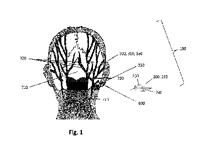
Fig. 1 depicts a schematic back view of a subject with a system
for unilateral neurostim-
ulation, comprising an implant unit and an external unit according to an
exemplary embodiment
of the present disclosure;
Fig. 2 depicts a schematic back view of a subject with a system
for bilateral neurostimu-
lation, comprising an implant unit and an external unit according to an
exemplary embodiment of
the present disclosure.
Fig. 3 depicts a schematic view of an exemplary embodiment of an
implant unit compris-
ing a unilateral modulation electrode configuration.
Fig. 4 depicts a schematic view of an exemplary embodiment of an
implant unit compris-
ing a bilateral modulation electrode configuration.
Fig. 5 depicts a flowchart of a system for treating head and
facial pain according to an
exemplary embodiment.
Detailed Description of the Exemplary Embodiments
Fig. 1 depicts a schematic back view of a subject with a system 100 for
unilateral neurostimulation,
the system comprising an implant unit 300 and an external unit 200 according
to an exemplary
embodiment of the present disclosure. The external unit 200 is configured for
location external to
the subject 700 or patient. The external unit 200 as shown in Fig. 1 is not
attached to the subject.
However, it may in fact be configured to be affixed to the subject 700. For
example, for a subject
suffering from head pain, the external unit 200 may be attached in the
vicinity of the mastoid
process, approximately at the level of the C2 vertebra. Suitable locations for
the external unit 200
may be determined by communication between external unit 200 and the implant
unit 300 im-
planted in the subject. The external unit 200 may comprise an external carrier
240 configured for
attachment to the subject's 700 skin. For example, the carrier 240 may be a
flexible skin patch
CA 03213321 2023- 9- 25
WO 2022/207316 - 16 -
PCT/EP2022/056789
configured for adherence to the subject's 700 skin, e.g. through adhesives or
mechanical means.
It is also possible to attach the external unit 200 to the subject's 700 skin
via magnetic force,
wherein the external carrier 240 comprises a magnetic pole, with a respective
opposite pole lo-
cated just beneath the subject's 700 skin. Further means of attachment can
include a Hook-and-
loop fastener based system (e.g. Velcro ). The external carrier 240 may be
flexible or rigid, or
may have flexible portions and rigid portions. The external carrier 240 and/or
the housing 250 of
the external unit 200 may be constructed of any suitable material. In
particular, the external unit
or the housing 250 may include a flexible material such that the external unit
may be configured
to conform to a desired location. The material of the flexible substrate may
include, but is not
limited to, plastic, silicone, woven natural fibers, and other suitable
polymers, copolymers, and
combinations thereof. Any portion of external unit may be flexible or rigid,
depending on the re-
quirements of a particular application.
The external unit 200 may further be configured to be affixed to an
alternative location proximate
to the subject. For example, in one embodiment, the external unit 200 may be
configured to fixedly
or removably adhere to a strap or a band that may be configured to wrap around
a part of a
subject's body. Alternatively, or in addition, the external unit 200 may be
configured to remain in
a desired location external to the subject's body without adhering to that
location.
The external unit 200 may comprise a housing 250. The housing 250 may include
any suitable
container configured for retaining components, e.g. a primary transmission
unit 230 or a proces-
sor 210. In addition, while the external unit 200 is illustrated schematically
in Fig. 1, the housing
250 may be any suitable size and/or shape and may be rigid or flexible.
The primary transmission unit 230 may be in the form of a coil antenna having
a diameter of about
0.5 cm to 5 cm, and may preferably be circular-shaped or oval-shaped. A coil
antenna suitable
for use as primary transmission unit may have any number of windings. Further,
a coil antenna
suitable for use as primary transmission unit may have a wire diameter of
about 0.1 mm to 2 mm.
As previously discussed, the external unit 200 may be configured to adhere to
a desired location.
Accordingly, in some embodiments, at least one side of the housing 250 or
external carrier 240
may include an adhesive material. The adhesive material may include a
biocompatible material
and may allow for a subject to attach the external unit 200 to the desired
location and remove the
external unit 200 upon completion of use. The adhesive may be configured for
single or multiple
uses of the external unit 200. Suitable adhesive materials may include, but
are not limited to
biocompatible glues, starches, elastomers, thermoplastics, and emulsions.
CA 03213321 2023- 9- 25
WO 2022/207316 - 1 7 -
PCT/EP2022/056789
Further, the external unit 200 may be associated with a power source 220. The
power source 220
may be removably couplable to the external unit 200 at an exterior location
relative to external
unit. Alternatively, the power source 220 may be permanently coupled to the
external unit 200. If
the power source 220 is permanently coupled to external unit 200, it is
intended that the power
source 220 be rechargeable. The power source 220 may further include any
suitable source of
power configured to be in electrical communication with the processor. In one
embodiment, for
example the power source 220 may include a battery 221.
The system of Fig. 1 further discloses an implant unit 300 comprising a
stimulation bridge 350,
the stimulation bridge 350 including a lead 310, the secondary transmission
unit 330 and pairs of
modulation electrodes 320. The lead 310 in Fig. 1 is approximately 10 cm long
and comprises
eight pairs of modulation electrodes 320 ("octopolar lead"), evenly spaced
apart along the lead
310. Further, the implant unit 300 is battery-free, making it possible for the
implant unit 300 to be
in the form of the stimulation bridge 350 shown in Fig. 1. The implant unit
300 is therefore suitable
for use in a neurostimulation system 100 as disclosed herein, since it is
configured for implantation
inside a subject's 700 body through an incision 600 the subject's 700 skin,
wherein the incision is
0.5 to 3.5 cm long. Furthermore, the implant unit 100 may be configured for
implantation inside a
tunnel 610 in the subject's tissue, wherein the tunnel 610 leads from the
incision 600 towards a
location in the vicinity of the subject's 700 inion 710, e.g. in a vicinity of
an occipital nerve 720.
Upon coupling of the primary transmission unit 230 of the external unit 200
with the secondary
transmission unit 330 of the implant unit 300, a sub-modulation signal or a
modulation signal may
be transmitted from the external unit 200 to the modulation electrodes 320 of
the implant unit 300.
A circuitry of the external unit 200 may for example be configured to generate
an electric primary
signal on the primary transmission unit 230 that may cause an electric
secondary signal on the
secondary transmission unit 330 in the implant unit 300. The secondary signal
may then be con-
figured to generate an electric field between the modulation electrodes 320,
sufficient to modulate
the terminal fibers of a nerve, when spaced apart thereof.
Fig. 2 depicts a schematic back view of a subject with a system 100 for
bilateral neurostimulation,
comprising an implant unit 300 and an external unit 200 according to an
exemplary embodiment
of the present disclosure. The embodiment shown in Fig. 2 differs from that of
Fig. 1 in that a long
lead 310 or stimulation bridge 350 is used, which is suitable for bilateral
stimulation. The lead 310
of the stimulation bridge 350 shown in Fig. 2 is approximately 20 cm long.
Preferably, it is config-
ured for an implantation procedure using two incisions 600.
In particular, bilateral neurostimulation requires one small incision 600 of 3
cm length at the level
of the mastoid process and a second incision 600, the second incision being
located 1 to 1.5 cm
CA 03213321 2023- 9- 25
WO 2022/207316 - 1 8 -
PCT/EP2022/056789
above the inion for implantation of the stimulation bridge 350. With a
stimulation 350 bridge having
a lead 310 that is longer than 10 cm, i.e. that is configured for bilateral
stimulation, it is possible
to stimulate a large neural area of the subject 700 with only to minor
incisions 600. Thus, the
medical procedure of implanting the implant unit in the subject 700 can be
kept short and still
allow for a very efficient neural stimulation.
Fig. 3 depicts a schematic view of an exemplary embodiment of an implant unit
300 comprising a
unilateral modulation electrode 320 configuration. In particular, the implant
unit 300 of Fig. 3 is
composed of the stimulation bridge 350 the secondary transmission unit 330.
The stimulation
bridge 350 comprises a lead 310 of approximately 10 cm of length as well as
and eight pairs of
modulation electrodes 320 (also labeled El to E8 in Fig. 3) attached to the
lead 310 ("octopolar
lead"). According to the embodiment shown in Fig. 3, the modulation electrodes
320 are evenly
spaced apart along the lead 310.
The implant unit 300 of Fig. 3 is battery-free, making it possible for the
implant unit 300 to be in
the slim and relatively small form of the stimulation bridge 350 shown in Fig.
3. Such an implant
unit 300 is suitable for use in a neurostimulation system 100 as disclosed
herein, since it is con-
figured for implantation inside a subject's 700 body through an incision 600
the subject's 700 skin,
wherein the incision is 0.5 to 3.5 cm long. Furthermore, the implant unit 300
may be configured
for implantation inside a tunnel 610 in the subject's 700 tissue, wherein the
tunnel 610 leads from
the incision 600 towards a location in the vicinity of the subject's 700 inion
710, e.g. in a vicinity
of an occipital nerve 720.
In the electrode 320 configuration of the stimulation bridge 350 of Fig. 3,
any individual modulation
electrode El to E8 can be programmed as an Anode (A) or a Cathode (C) or it
can be left uncon-
nected (NC). According to a preferred embodiment, at least one electrode 320
may be defined as
Anode and/or at least one electrode 320 may be defined as Cathode. The
remaining to two to
seven electrodes may be put in parallel as Anode or Cathode.
Fig. 4 depicts a schematic view of an exemplary embodiment of an implant unit
300 comprising
a bilateral modulation electrode 320 configuration. The implant unit 300 of
Fig. 4 differs from the
embodiment of Fig. 3 in the stimulation bridge 350 comprises a longer lead
310, suitable for bi-
lateral stimulation. The lead 310 of the stimulation bridge 350 shown in Fig.
3 is approximately 20
cm long.
As shown on Fig. 4, the stimulation bridge 350 is made up of two connected
segments, each
segment comprising eight pairs of modulation electrodes 320a and 320b
respectively. The mod-
ulation electrodes 320a attached to the segment of the stimulation bridge 350
that is connected
CA 03213321 2023- 9- 25
WO 2022/207316 - 1 9 -
PCT/EP2022/056789
to the secondary transmission unit 330 are called proximal electrodes 320a
(also labeled PEI to
PE8 in Fig. 4). Likewise, the modulation electrodes 320b attached to the
segment of the stimula-
tion bridge 350 that is not directly connected to the secondary transmission
unit 330 are called
distal electrodes 320b (also labeled DE1 to DE8 in Fig. 4).
According to the electrode 320 configuration of the stimulation bridge 350 of
Fig. 4, any individual
modulation electrode PEI to PE8 or DE1 to DE8 can be programmed as an Anode
(A) or a Cath-
ode (C) or it can be left unconnected (NC). According to a preferred
embodiment, at least one
electrode 320 may be defined as Anode and/or at least one electrode 320 may be
defined as
Cathode.
Fig. 5 depicts a flowchart of a system 100 for treating head and facial pain
according to an exem-
plary embodiment. According to this embodiment, an external unit 200 may be
attached to the
external carrier 240 which is attached to a patient's skin. This "patient
external unit" 200 (Patient
EU in Fig. 5) establishes, via its primary transmission unit 230, a
transmission link with an implant
unit 300 implanted beneath the patient's 700 skin_ Furthermore, the "patient
external unit" 200
may supply power to the implant unit 300 via induction.
According to the shown embodiment of the system 100, the implant unit 300 is
configured to
communicate with the external unit 200 via wireless transmission. The implant
unit may further
comprise a bootloader which starts a software program installed on a processor
of the implant
unit. Lastly, the implant unit 300 may be configured to run and diagnose
stimulation therapy and
send alters and warnings (A&VV) to the external unit 200 in case the implant
unit 300 encounters
problems.
The system 100 further comprises a charging unit 400 for charging the external
unit 200 via in-
ductive coupling. However, according to the embodiment of Fig. 5, the charging
unit 400 may
further be configured to collect A&W data stored on the patient external unit
200 and sent to the
external unit 200 from the implant unit 300. Furthermore, the charging unit
400 may comprise a
charger LED and an emergency LED, which can be turned on or off. E.g. the
charger LED may
be turned on for as long as the external unit 200 is being charged. Likewise,
the emergency LED
may be turned on when the charging unit 400 receives A&W data from the
external unit 200.
Additionally, the charging unit 400 may connect to a web server and upload log
files or A&W
reports.
Lastly, as shown by Fig. 5 the system 100 may comprise a physician programming
unit 800 con-
nectable to the external unit 200. When the external unit 200 is connected to
the physician pro-
gramming unit 800, it may also be referred to as "physician external unit" 200
(see Physician EU
CA 03213321 2023- 9- 25
WO 2022/207316 - 20 -
PCT/EP2022/056789
in Fig. 5). The "physician external unit" 200 may then either be the same
device as the "patient
external unit" (see Patient EU in Fig. 5) or it may be a different external
device used solely by the
physician. The physician programming unit 800 may be an external computing
unit, e.g. a PC or
a similar handheld or portable device like a tablet or a smartphone. Together,
the physician ex-
ternal unit 200 and the physician programming unit 800 are configured to
prepare a therapy tem-
plate and store its configuration under specific names. Furthermore, the
physician programming
unit 800 may serve for secure identification of the implant unit 300 and
establish a secure pairing
between the implant unit 300 and the physician external unit 200. Further
functions of the physi-
cian programming unit 800 and the physician programming unit 200 may comprise:
Verifying pa-
tient history log files stored in the implant unit 300; prepare/load a therapy
and run a test stimula-
tion sequence during patient visits; program the tested therapy during patient
visits; receive a
status report from the implant unit 300 (e.g. alerts or warnings, history log
files, etc.) during the
patient visits; provide a user-friendly interface to visualize the therapy
before programming (e.g.
show electrode configuration, current amplitudes, pulse durations, ON-OFF
period, etc.).
The invention is not limited to one of the embodiments described herein but
may be modified in
numerous other ways.
All features disclosed by the claims, the specification and the figures, as
well as all advantages,
including constructive particulars, spatial arrangements and methodological
steps, can be essen-
tial to the invention either on their own or by various combinations with each
other.
CA 03213321 2023- 9- 25
WO 2022/207316 - 21 -
PCT/EP2022/056789
List of reference numerals
100 System
200 External unit
210 Processor
220 Power source
221 Battery
230 Primary transmission unit
240 External carrier
250 Housing
260 Energy harvesting unit
300 Implant unit
310 Lead
320 Modulation electrodes
330 Secondary transmission unit
340 Flexible carrier
350 Stimulation bridge
400 Charging unit
500 Remote control
600 Incision
610 Tunnel
700 Subject
710 I nion
720 Occipital nerve
800 Physician programming unit
CA 03213321 2023- 9- 25