Note: Descriptions are shown in the official language in which they were submitted.
CA 03213634 2023-09-15
t
1
Method for controlling an agricultural spreading machine
Description
The invention relates to a method for controlling an agricultural spreading
machine
according to the preamble of patent claim 1 and a spreading system for
distributing
spreading material according to the preamble of patent claim 11.
Trailed spreading machines able to carry a comparatively large quantity of
spreading
material due to a large-volume storage tank are regularly used to distribute
spreading
material on large agricultural areas. Such spreading machines often have a
conveyor
belt for conveying the spreading material, by means of which the spreading
material is
transported in the direction of the spreading discs and discharged from the
conveyor
belt in the direction of the spreading discs in a ejection plane.
For quantity adjustment of the spreading material fed onto the spreading
discs, slide
systems are used in practice, with which the free conveying cross-section
above the
conveyor belt may be adjusted. Such slide systems have a main slide, with
which the
quantity may be preset. Two hydraulically actuated closing slides may be
arranged
downstream of the main slide and in the vicinity of the ejection plane of the
conveyor
belt, by means of which the feed of the spreading material onto the spreading
discs
may be prevented individually for each disc.
The known solutions for quantity adjustment on spreading machines, in which a
conveyor belt is used to convey the spreading material, have two disadvantages
in
particular. In wedge spreading, one of the two closing slides is initially
closed, so that
the spreading material collects in front of the closed slide due to the
continuing
conveyor belt. When the closing slide is subsequently opened, for example in
the next
lane, the accumulation of spreading material in front of the closing slide and
the
flowability of the spreading material cause an excessive amount of spreading
material
to be fed onto the spreading disc, resulting in localized misapplication.
Especially when
discharging spreading material on comparatively long wedge-shaped surface
sections,
an overflow of the spreading material over the closing slide or its upper
boundary edge
may even occur, whereby spreading material reaches the spreading discs and/or
the
working surface in an uncontrolled manner. Preventing such an overflow is
extremely
costly due to design-related specifications, as it is then no longer possible
to implement
an upstream quantity adjustment.
CA 0,3213634 2023-09-15
2
From EP 1 869 962 B1 there is known a metering system operating without a main
slide. In the case of the discharging of spreading material described there,
however,
when the discharge of spreading material is temporarily interrupted by
stopping the
conveyor belt, spreading material lies in the immediate vicinity of the
ejection plane at
least on a partial width of the conveyor belt. When the belt conveying is
continued,
spreading material is then inevitably fed directly onto the spreading disc on
this side,
regardless of whether this is intended or not. For this reason, unintentional
discharging
of spreading material on the inside of a curve at the end of a turning
operation in the
headland cannot be avoided, so that over-fertilization occurs in the inside of
the curve
during every turning operation between two parallel runs. Due to the fact that
spreading
material is in the immediate vicinity of the ejection plane during the
temporary
interruption of the discharge of spreading material, there is also a risk that
spreading
material will fall uncontrollably onto the spreading disc and/or the working
surface
during bumpy driving, for example due to uneven ground.
In order to overcome the problems described above, spreading machines are also
used in practice, which instead of spreading discs have a spreading linkage
with a
plurality of spreading elements, whereby the spreading material is conveyed
pneumatically in these machines. Such a spreading machine is known, for
example,
from EP 3 662 734 A1.
The object to be addressed by the invention is thus to at least partially
overcome the
aforementioned disadvantages in discharging spreading material with an
agricultural
spreading machine, in which a conveyor belt is used to convey the spreading
material.
The object is solved by a method as referred to at the beginning, wherein a
control
device within the scope of the method according to the invention for
temporarily
interrupting the discharging of spreading material at a shut-off location on
the
agricultural area causes the feed-rate-setting device to prevent the
discharging of
spreading material into the idling section at an early stage before the shut-
off location is
reached, so that the idling section of the conveyor belt has run empty when
the shut-off
location is reached.
After the temporary interruption in discharging, there is no spreading
material in the
vicinity of the ejection plane, as the idling section has already run empty.
As a result,
there is no risk of spreading material falling unintentionally onto the
spreading disc
during bumpy driving. Furthermore, when discharging of spreading material is
continued, there is no spreading material in the vicinity of the ejection
plane. Thus,
when the discharging of spreading material continues after or during a turning
CA 03213634 2023-09-15
3
operation, there is never any spreading material on the wrong side of the
idling section,
so that no unintentional local excessive or insufficient discharging of
spreading material
occurs. If the spreading material is fertilizer, over-fertilization or under-
fertilization is
effectively avoided when performing turning operations, such as on the
headland. This
may also significantly reduce the risk of spreading in hazardous areas, for
example at a
field boundary or at a body of water.
The control device may be part of the spreading machine. Alternatively, the
control
device may be a device external to the machine. The control device may, for
example,
be a terminal, in particular an Isobus terminal, which is connected to the
spreading
machine in a signal-conducting manner. The temporary interruption of the
discharging
of spreading material takes place, for example, at the transition to the
headland or at
the end of a wedge spreading operation. The spreading material is conveyed by
means
of the conveyor belt from a reservoir in the direction of the spreading discs.
The
conveyor belt is preferably of a revolving design. The conveyor belt
preferably has a
belt drive. The spreading discs are preferably arranged side by side. The
operation of
the conveyor belt and the feed-rate-setting device is preferably controlled by
means of
the control device.
In a preferred embodiment of the method according to the invention, the
control device
for continuing the discharging of spreading material at a switch-on location
on the
agricultural area causes the feed-rate-setting device to trigger the conveying
of
spreading material into the idling section early before the switch-on location
is reached,
so that the conveyor belt is loaded with spreading material along the entire
idling
section at least over a partial width when the switch-on location is reached.
When the
switch-on location is reached, at least part of the width of the idling
section is thus
loaded with spreading material up to the ejection plane, so that the spreading
material
may be fed to the spreading discs immediately without delay when the switch-on
location is passed.
In a further preferred embodiment of the method according to the invention,
the
spreading material leaving the idling section and located on a first partial
width of the
idling section is discharged from the conveyor belt in the ejection plane in
the direction
of a first spreading disc of the spreading machine. Alternatively or
additionally, the
spreading material leaving the idling section and located on a second partial
width of
the idling section is discharged from the conveyor belt in the ejection plane
in the
direction of a second spreading disc of the spreading machine. The first
partial width of
the idling section is thus assigned to a first spreading disc, the second
partial width of
the idling sectionbeing assigned to a second spreading disc. In this respect,
the feed of
CA 03213634 2023-09-15
4
spreading material to the first spreading disc may be adjusted via the loading
of the first
partial width of the idling section, while the feed of spreading material to
the second
spreading disc may be adjusted via the loading of the second partial width of
the idling
section.
In a further embodiment of the method according to the invention, the feed-
rate-setting
device sets the feed quantity of spreading material entering a first partial
width of the
idling section in the feed setting plane by means of a first feed-rate
limiter. Alternatively
or additionally, the feed-rate-setting device sets the feed quantity of
spreading material
entering a second partial width of the idling section in the feed setting
plane by means
of a second feed-rate limiter. The partial widths of the idling section are
partial widths of
the idling section, for example, the first partial width of the idling section
is the left side
and the second partial width of the idling section is the right side of the
idling section.
Preferably, the feed quantity limiters each include a feed slide that may be
lowered
onto the conveyor belt and lifted off the conveyor belt. The feed-rate-setting
device may
thus be a double slide device. The feed slides are preferably each connected
to a slide
drive, by means of which the respective feed slide may be raised and lowered.
The
slide drives may preferably be controlled independently of one another. The
slide
drives may be electric drives. Alternatively, the slide drives may be
pneumatic or
hydraulic drives. By means of the slide drives, the free feed cross-section
above the
conveyor belt may preferably be adjusted in the inlet area of the first
partial width of the
idling section and in the inlet area of the second partial width of the idling
section.
In addition, it is advantageous to have a method in which, at a spreading
boundary of
the agricultural area extending at right angles to the direction of travel of
the spreading
machine, the control device, when temporarily interrupting the discharging of
spreading
material at a shut-off location on the agricultural area, simultaneously
causes the first
feed rate limiter and the second feed rate limiter of the feed-rate-setting
device to close
at a common time, to prevent spreading material from being conveyed into the
first
partial width of the idling section and the second partial width of the idling
section early
before the shut-off location is reached, so that the first partial width of
the idling section
and the second partial width of the idling section run empty synchronously
before the
shut-off location is reached. A spreading boundary running at right angles to
the
direction of travel of the spreading machine results in particular in the
transition areas
to the headland, in which the headland lane runs at right angles to the lanes
inside the
field. As the first idling section and the second idling section run
synchronously empty
before reaching the shut-off location, spreading is interrupted synchronously
on both
sides.
CA 03213634 2023-09-15
In a further preferred embodiment of the method according to the invention,
the control
device, at a spreading boundary of the agricultural area extending obliquely
to the
direction of travel of the spreading machine, causes the first feed rate
limiter of the
feed-rate-setting device to close at a first time and the second feed rate
limiter of the
feed-rate-setting device to close at a second time, with a time delay from one
another,
when spreading is temporarily interrupted at a shut-off location on the
agricultural area,
to prevent the conveyance of spreading material into the first partial width
of the idling
section and the second partial width of the idling section early before the
shut-off
location is reached, so that the first partial width of the idling section and
the second
partial width of the idling section idle asynchronously before the shut-off
location is
reached. As a result of the asynchronous idling of the first partial width of
the idling
section and the second partial width of the idling section, spreading is first
interrupted
on one side before the entire spreading process is interrupted. If the
spreading
boundary runs diagonally to the direction of travel of the spreading machine,
for
example, a wedge spreading situation or a diagonally running headland is
present.
In a further embodiment of the method according to the invention, the control
device
calculates the common closing time in the case of a spreading boundary of the
agricultural area running at right angles to the direction of travel of the
spreading
machine as a function of an intended travel speed until the shut-off location
is reached.
Alternatively or additionally, the control device calculates the first closing
time and/or
the second closing time for a spreading boundary of the agricultural area
running
obliquely to the direction of travel of the spreading machine as a function of
an
intended travel speed until the shut-off location is reached. Furthermore, the
control
device takes into account the current position and/or the position of the shut-
off location
or the distance to the shut-off location when calculating the closing time.
Furthermore,
when calculating the closing time, the control device may also take into
account the
duration until the shut-off location is reached, which results from the
distance to the
shut-off location and the travel speed until the shut-off location is reached.
A satellite
navigation system may be used to determine the position, for example GPS or
DGPS.
The control device may calculate the common closing time or the first closing
time
and/or the second closing time alternatively or additionally also taking into
account the
actual or current travel speed or taking into account a selected travel speed.
In a further preferred embodiment of the method according to the invention,
the first
feed rate limiter and the second feed rate limiter of the feed-rate-setting
device each
perform a closing process for completely preventing the feed of spreading
material into
the first partial width of the idling section and the second partial width of
the idling
CA 03213634 2023-09-15
6
section, the closing process extending over a closing period. The conveyed
quantity of
spreading material entering the first partial width of the idling section
drops due to the
closing process of the first feed rate limiter during the closing time of the
first feed rate
limiter. Alternatively or additionally, the conveyed quantity of spreading
material
entering the second partial width of the idling section drops due to the
closing process
of the second feed rate limiter during the closing time of the second feed
rate limiter.
During the closing period, there is an increasing blocking of the free feed
cross-section
in the inlet area of the partial width of the idling sections by the
respective feed rate
limiter, so that a loading ramp is created on the partial width of the idling
sections
during the closing process. During the closing process, the loading ramp drops
in the
opposite direction to the conveying direction. Opening processes of the first
feed rate
limiter and the second feed rate limiter also extend over an opening duration,
wherein a
loading ramp also is obtained for the partial width of the idling sections
during the
opening process. During the opening process, however, the loading ramp drops
in the
conveying direction.
In another preferred embodiment of the method according to the invention, the
control
device adapts the belt speed of the conveyor belt during the closing process
of the first
and/or the second feed rate limiter to the falling feed quantity of spreading
material on
the first partial width of the idling section and/or the second partial width
of the idling
section. Preferably, the belt speed increases with decreasing feed quantity of
spreading material on the first partial width of the idling section and/or the
second
partial width of the idling section. When adjusting the belt speed of the
conveyor belt,
the control device preferably also takes into account the spread pattern to be
produced,
the travel speed and/or the closing speed of the first and/or the second feed
rate
limiters.
Furthermore, a method according to the invention is advantageous, in which the
feed-
rate-setting device adjusts the feed quantity of spreading material entering
the idling
section by partially or completely blocking the free feed cross-section above
the
conveyor belt. The adjustment of the free feed cross-section above the
conveyor belt is
preferably carried out by lowering and raising the feed slides of the feed
rate limiters.
The problem to be addressed by the invention is further solved by a spreading
system
of the type referred to at the beginning, wherein the spreading system
according to the
invention has a control device that is configured to cause, for the temporary
interruption
of the discharging of spreading material at a shut-off location on the
agricultural area,
the feed-rate-setting device to prevent the delivery of spreading material
into the idling
CA 03213634 2023-09-15
7
section early before the shut-off location is reached, so that the idling
section of the
conveyor belt has run empty when the shut-off location is reached.
In a preferred embodiment, the spreading system according to the invention is
configured to perform the method of controlling an agricultural spreading
machine
during the spreading or discharging of spreading material on an agricultural
land
according to any of the embodiments described above. With respect to the
advantages
and modifications of the spreading system according to the invention,
reference is thus
made to the advantages and modifications of the method according to the
invention.
In the following, preferred embodiments of the invention are explained and
described in
more detail with reference to the accompanying figures. In the figures:
Fig. 1 shows an embodiment of the spreading system according to the invention
in a
perspective view;
Fig. 2 shows an additional embodiment of the spreading system according to the
invention in a plan view;
Fig. 3 shows an agricultural spreading machine during discharging of spreading
material, wherein the agricultural spreading machine is controlled by the
method
according to the invention;
Fig. 4 depicts an agricultural spreading machine during discharging of
spreading
material, wherein the agricultural spreading machine is controlled by the
method
according to the invention;
Fig. 5A illustrates
spreading material loading state of a partial width of the idling
section including the feed rate limiter during spreading of spreading
material;
Fig. 6 shows a further spreading material loading state of a partial width of
the idling
section together with the feed rate limiter during discharging of spreading
material;
Fig. 7 shows another spreading material loading state of a partial width of
the idling
section together with the feed rate limiter during discharging of spreading
material;
CA 03213634 2023-09-15
=
8
Fig. 8 shows a further spreading material loading state of a partial width of
the idling
section including the feed rate limiter during discharging of spreading
material;
and
Fig. 9 shows a further spreading material loading state of a partial width of
the idling
section together with the feed rate limiter during discharging of spreading
material.
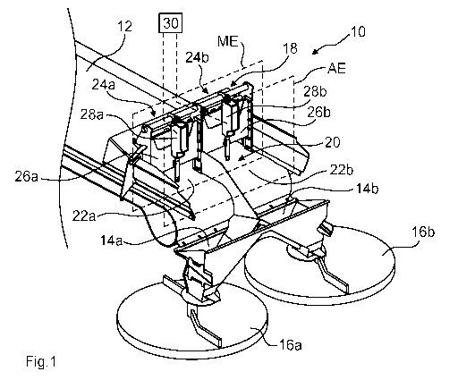
Fig. 1 shows a spreading system 10 for discharging spreading material S on an
agricultural area. The spreading system 10 may, for example, be a component of
an
agricultural spreading machine, the agricultural spreading machine being, for
example,
a twin-disc fertilizer spreading machine.
The spreading system 10 includes a conveyor belt 12, by means of which
spreading
material may be transported from a reservoir to a first spreading disc 16a and
a second
spreading disc 16b. The conveyor belt 12 conveys the spreading material S to
be
discharged along an idling section 20 relating to a longitudinal section LA of
the
conveyor belt 12, which lies between a rate setting plane ME and an ejection
plane AE.
The feed quantity of spreading material S leaving the idling section 20 is
discharged in
the ejection plane AE in the direction of the spreading discs 16a, 16b. Guide
bodies
14a, 14b are arranged between the conveyor belt 12 and the spreading discs
16a, 16b,
which are designed as funnels and bring together the spreading material S
leaving the
conveyor belt 12 before it hits the spreading discs 16a, 16b.
The spreading system 10 further includes a feed-rate-setting device 18, by
means of
which the delivery rate of spreading material S entering the idling section 20
may be
set in the rate setting plane ME.
The idling section 20 is divided into a first partial width 22a of the idling
section and a
second partial width 22b of the idling section. The spreading material S
leaving the
idling section 20 and located on the first partial width 22a of the idling
section is
discharged from the conveyor belt 12 in the ejection plane AE in the direction
of the
first spreading disc 16a. The spreading material S leaving the idling section
20 and
located on the second partial width 22b of the idling section is discharged
from the
conveyor belt 12 in the ejection plane AE in the direction of the second
spreading disc
16b.
The feed-rate-setting device 18 has a first feed rate limiter 24a arranged in
the rate
setting plane ME. By means of the first feed rate limiter 24a, the feed rate
of spreading
material S entering the first partial width 22a of the idling section may be
adjusted. The
CA 03213634 2023-09-15
9
feed-rate-setting device 18 further includes a second feed rate limiter 24b in
the rate
setting plane ME, by means of which the feed quantity of spreading material S
entering
the second partial width 22b of the idling section may be set.
The feed rate limiters 24a, 24b each include a feed slide 26a, 26b which may
be
lowered onto and raised from the conveyor 12. The feed slides 26a, 26b are
each
connected to a slide drive 28a, 28b by which the respective feed slide 26a,
26b may be
raised and lowered. The slide drives 28a, 28b are electric drives.
The slide drives 28a, 28b and the belt drive of the conveyor belt 12 are
connected in a
signal-conducting manner to a control device 30 of the spreading system 10.
The
control device 30 may be an internal machine control device or an external
machine
control device. For example, the control device 30 is a terminal, in
particular an isobus
terminal.
The control device 30 is configured to cause the feed-rate-setting device 18
to prevent
the transport of spreading material S into the idling section 20 at an early
stage before
the shut-off location AO, A02 (cf. Figs. 3 and 4) is reached, so that the
idling section 20
of the conveyor belt 12 is idled when the shut-off location AO, A02 is
reached.
Furthermore, the control device 30 is arranged to cause the feed-rate-setting
device to
trigger the feed of spreading material S into the idling section 20 early
before the
switch-on location E0, E01 (cf. Figs. 3 and 4) is reached, so that the
conveyor belt 12
is loaded with spreading material S over at least a partial width along the
entire idling
section 20 when the switch-on location EO, E01 is reached.
Fig. 2 shows that the partial widths 22a, 22b of the idling sections are
adjacent partial
widths of the idling sections 20, which extend along a longitudinal section LA
of the
conveyor belt 12. The longitudinal section LA is located between the rate
setting plane
ME and the ejection plane AE.
Fig. 3 shows a headland situation, in which a spreading boundary runs at right
angles
to the direction of travel of the spreading machine. Fig. 3 shows the
different loading
states of the partial widths 22a, 22b of the idling section as well as the
opening states
of the feed rate limiters 24a, 24b while performing a headland turning
operation.
When approaching the headland lane, the partial widths 22a, 22b of the idling
section
are initially continuously and uniformly loaded with spreading material S and
the feed
rate limiters 24a, 24b are in an open state. Fig. 5 shows the loading state of
the partial
width 22b of the idling section and the opening state of the feed rate limiter
24b in
detail.
CA 03213634 2023-09-15
=
When approaching the headland lane, the control device 30 initiates the
closing of the
feed rate limiters 24a, 24b in good time before reaching a shut-off location
AO on the
agricultural land. The closing operation is initiated by the control device 30
at a closing
time. Fig. 6 shows the loading state of the partial width 22b of the idling
section and the
closed feed rate limiter 24b in detail. From the illustration, it can be seen
that the
conveyed quantity of spreading material S on the partial width 22b of the
idling section
has a loading ramp BR, which is obtained due to the movement of the conveyor
belt 12
with simultaneous closing movement of the feed slide 26b of the feed rate
limiter 24b.
When the headland lane is approached further, both feed rate limiters 24a, 24b
are
then already closed, so that the feed of spreading material S into the partial
widths 22a,
22b of the idling section is prevented. The partial widths 22a, 22b of the
idling section
therefore run synchronously empty before reaching the shut-off location AO.
The idling
situation is shown in detail in Fig. 7.
When the shut-off location AO is reached before the headland lane, both
partial widths
22a, 22b of the idling section are completely empty, so that the turning
operation is
carried out with an unloaded idling section 20. Fig. 8 shows the partial width
22b of the
idling section in detail.
After the turning operation has been carried out, the partial widths 22a, 22b
of the idling
section are filled again with spreading material S by opening the feed rate
limiters 24a,
24b in good time before the switch-on location ED is reached. Fig. 9 shows the
filling
process of the partial width 22b of the idling section in detail. Due to the
opening
process of the feed rate limiter 24b, a loading ramp BR again is obtained on
the partial
width 22b of the idling section.
The control device 30 calculates the closing time for the feed rate limiters
24a, 24b
when approaching the headland and the opening time for the feed rate limiters
24a,
24b when leaving the headland as a function of an intended travel speed until
the shut-
off location AO or the switch-on location ED is reached.
Fig. 4 shows a spreading situation with the spreading boundary of the
agricultural area
running diagonally to the direction of travel. In this spreading situation,
the partial
widths 22a, 22b of the idling section run asynchronously empty. Initially, the
partial
widths 22a, 22b of the idling section are both completely and uniformly loaded
with
spreading material S and the feed rate limiters 24a, 24b are in an open state.
When
approaching the headland lane, the feed rate limiter 24b at the outer curve
side is
closed first, so that the partial width 22b of the idling section runs empty
when
CA 03213634 2023-09-15
. .
11
approaching the headland lane further. With a time delay, the feed rate
limiter 24a on
the inside of the curve is then closed so that the partial width 22a of the
idling section
runs empty as the headland lane is approached further. Thus, the control
device 30
causes the feed rate limiter 24b to close early before the shut-off location
A01 is
reached, and causes the feed rate limiter 24b to close early before the shut-
off location
A02 is reached. During the turning operation, both partial widths 22a, 22b of
the idling
sectionare then completely idle.
When driving out of the headland, the feed rate limiter 24b at outer curve
side is
opened first so that the partial width 22b of the idling section at the outer
curve side is
fed with spreading material S. The feed rate limiter 24a at the inner curve
side is then
opened after a time interval so that the partial width 22a of the idling
section at the
inner curve side is filled with spreading material S. The feed rate limiter
24a at the inner
curve side is then opened at a time interval so that the partial width 22a of
the idling
section at the inner curve side is fed with spreading material S. The opening
of the feed
rate limiter 24b is thus initiated in good time before the switch-on location
E01 is
reached. The opening of the feed rate limiter 24a is initiated in good time
before the
switch-on location E02 is reached.
As a result of the fact that in the spreading situations shown in Figs. 3 and
4 no
spreading material S is provided on the idling section 20 during the turning
operation,
there is no risk of spreading material S unintentionally falling onto the
spreading discs
16a, 16b during bumpy driving. Furthermore, it is prevented that spreading
material S
lies on the wrong side of the idling section 20 during an intended
continuation of
discharging of spreading material after or during a turning operation, so that
no
unintended local excessive spreading of spreading material, for example
fertilizer,
takes place in the area inside the curve when carrying out turning operations.
CA 03213634 2,023-09-15
, ,
12
List of reference signs
Spreading system
12 Conveyor belt
14a, 14b Guide body
16a, 16b Spreading discs
18 Feed-rate-setting device
Idling section
22a, 22b Partial widths of the idling section
24a, 24b Feed rate limiter
26a, 26b Feed slider
28a, 28b Slide drives
Control device
AE Ejection plane
AO, A01, A02 Shut-off locations
BR Loading ramp
EO, E01, E02 Switch-on locations
LA Longitudinal section
ME Rate setting plane
S Spreading material