Note: Descriptions are shown in the official language in which they were submitted.
CA 03215579 2023-09-28
WO 2022/211804 PCT/US2021/025139
- 1 -
VIBRATIONAL POWDER APPLICATOR
FIELD
[0001] Disclosed embodiments are related to powder applicators and
associated
methods.
BACKGROUND
[0002] Powder applicators are used in many different applications to
apply various
types of powders to a desired surface, such as in the delivery of therapeutic
powders to a
desired location of a subject for therapeutic purposes. Powders that are
delivered using these
applicators tend to be lightweight, low-density powders with a Hausner ratio
between 1.00
and 1.18. Some applicators fluidize a powder by directing a flow of gas toward
the powder.
SUMMARY
[0003] In some embodiments, a method of applying a therapeutic powder
includes
positioning an outlet of a powder applicator containing a therapeutic powder
below a powder
storage chamber of the powder applicator relative to a local direction of
gravity, vibrationally
agitating the therapeutic powder, and dispensing at least a portion of the
therapeutic powder
through the outlet of the powder applicator.
[0004] In some embodiments, a vibrational powder applicator includes a
powder
storage chamber, a therapeutic powder disposed within the powder storage
chamber, an
actuator operatively coupled to the powder storage chamber and configured to
vibrationally
agitate the therapeutic powder when activated, and an outlet in fluid
communication with the
powder storage chamber.
[0005] In some embodiments, a vibrational powder applicator includes a
powder
storage chamber configured to contain a powder, an actuator operatively
coupled to the
powder storage chamber and configured to vibrationally agitate the powder when
activated,
an outlet in fluid communication with the powder storage chamber, and a flow
restrictor
disposed between the powder storage chamber and the outlet.
[0006] In some embodiments, a vibrational powder applicator includes a
powder
storage chamber configured to contain a powder, an actuator operatively
coupled to the
CA 03215579 2023-09-28
WO 2022/211804 PCT/US2021/025139
- 2 -
powder storage chamber and configured to vibrationally agitate the powder when
activated,
an outlet in fluid communication with the powder storage chamber, and a valve
disposed
between the powder storage chamber and the outlet. The valve is configured to
selectively
permit or prevent flow of the powder from the powder storage chamber to the
outlet.
[0007] It should be appreciated that the foregoing concepts, and
additional concepts
discussed below, may be arranged in any suitable combination, as the present
disclosure is
not limited in this respect. Further, other advantages and novel features of
the present
disclosure will become apparent from the following detailed description of
various non-
limiting embodiments when considered in conjunction with the accompanying
figures.
BRIEF DESCRIPTION OF DRAWINGS
[0008] The accompanying drawings are not intended to be drawn to scale.
In the
drawings, each identical or nearly identical component that is illustrated in
various figures
may be represented by a like numeral. For purposes of clarity, not every
component may be
labeled in every drawing. In the drawings:
[0009] FIG. 1 is a cross-sectional schematic of one embodiment of a
vibrational
powder applicator;
[0010] FIG. 2A is a top view of one embodiment of a vibrational powder
applicator;
[0011] FIG. 2B is a cross-sectional side view of the vibrational powder
applicator of
FIG. 2A taken along line 2B-2B;
[0012] FIG. 3A is a cross-sectional back view of one embodiment of a flow
restrictor;
[0013] FIG. 3B is a cross-sectional side view of a distal end of one
embodiment of a
vibrational powder applicator that includes the flow restrictor of FIG. 3A
taken along line
3B-3B;
[0014] FIG. 4A is a cross-sectional back view of a first embodiment of a
flow
restrictor with a first number of fins;
[0015] FIG. 4B is a cross-sectional back view of a second embodiment of a
flow
restrictor with a second number of fins;
[0016] FIG. 4C is a cross-sectional back view of a third embodiment of a
flow
restrictor with a third number of fins;
CA 03215579 2023-09-28
WO 2022/211804 PCT/US2021/025139
- 3 -
[0017] FIG. 4D is a cross-sectional back view of a fourth embodiment of a
flow
restrictor with a fourth number of fins; and
[0018] FIG. 5 is a cross-sectional side view of one embodiment of a
vibrational
powder applicator that includes a valve.
DETAILED DESCRIPTION
[0019] Therapeutic powders may vary both in particle size and density.
These
properties impact the flow character, or flowability, of the powder. The
Hausner ratio, which
is calculated by dividing the measured tapped density of a powder by its bulk
density, can be
used to assess the flowability of a powder. Generally, the lower the Hausner
ratio, the better
the flowability. For example, powders with a Hausner ratio between 1.00 and
1.18 may be
considered to exhibit excellent to good flow characteristics, whereas powders
with a Hausner
ratio above 1.18 exhibit fair to poor flow characteristics. There may also be
other powder
characteristics such as particle morphology, basic flowability energy, aerated
energy, aeration
ratio, wall friction angle, compression percent, static charge, moisture
content, and other
appropriate parameters which may be used to characterize the overall
flowability of a
powder. Particles with poor flowability are relatively difficult to fluidize,
which may make
them ill-suited for certain application methods.
[0020] Hemostatic powders are therapeutic powders that are used to manage
or stop
bleeding. These powders are commonly applied via applicators. Conventional
applicators
may use pressurized gas (which may be generated by a manual bellows, or an
automated gas
flow, for example) in order to fluidize the powder for delivery towards a
target area, such as a
bleed site. Existing applicators use relatively high pressure and/or high
velocity gas, and are
generally effective at fluidizing and applying hemostatic powders with
relatively small
particle sizes and/or relatively low densities. Such hemostatic powders may
exhibit Hausner
ratios between 1.00 and 1.18. However, these small particle size and/or low-
density
hemostatic powders may be ineffective at breaking the surface tension of
flowing blood, and
therefore may not reach a desired location beneath the flowing blood.
Accordingly, the use of
larger and/or more dense powders capable of breaking the surface tension of
flowing blood
may be advantageous in certain applications. However, larger and/or more dense
powders
may be difficult to fluidize using standard pressure-based applicators.
Furthermore, using
CA 03215579 2023-09-28
WO 2022/211804 PCT/US2021/025139
- 4 -
pressurized gas to expel larger and/or more dense powders may result in
reduced
controllability and limited delivery precision.
[0021] In view of the above, the Inventors have recognized the benefits
of an
improved therapeutic powder applicator capable of focal dispensing of powder
(including
relatively large and/or dense powder) in a specific delivery area. Such an
applicator may be
configured to effectively fluidize and apply therapeutic powders in a
controlled, targeted, and
repeatable fashion. Whereas conventional applicators may be limited to
applying hemostatic
powders in a relatively coarse and/or imprecise fashion, an improved
applicator may be
capable of delivering a variety of different types, sizes, and densities of
powders in a
controllable fashion, and may enable focused delivery of powder to a precise
target area in
some embodiments.
[0022] In view of the above, the Inventors have recognized the benefits
of an
applicator that may control the delivery of powder from the applicator using
vibration.
Without wishing to be bound by theory, applying vibrational energy to a powder
(e.g.,
powder that is disposed within an applicator) may be associated with
fluidizing the powder
such that the powder may flow under the influence of gravity. When an
applicator containing
a powder is held in certain orientations, applying vibrational energy to the
powder may
fluidize the powder and allow the powder to flow from a powder storage chamber
within the
applicator toward a tip of the applicator and out of an outlet of the
applicator. Such a
vibrational powder applicator may enable controllable, focused, precise, and
repeatable
delivery of powder.
[0023] In some embodiments, a vibrational powder applicator includes a
powder
storage chamber configured to contain a powder, such as a therapeutic powder
(e.g., a
hemostatic powder). An actuator may be operatively coupled to the powder
storage chamber
and configured to vibrationally agitate the powder when activated. An outlet
of the applicator
may be in fluid communication with the powder storage chamber. In some
embodiments, the
powder storage chamber and the outlet are configured such that the powder may
move from
the powder storage chamber toward the outlet when the powder is vibrationally
agitated by
the actuator. For example, a vibrational powder applicator may include a
proximal end and a
distal end. The powder storage chamber may be associated with the proximal
end, and the
outlet may be associated with the distal end. When the applicator is oriented
such that the
CA 03215579 2023-09-28
WO 2022/211804 PCT/US2021/025139
- 5 -
distal end (and the outlet) is below the proximal end (and the storage
chamber) relative to a
local direction of gravity, vibrationally agitating the powder may fluidize
the powder and
allow the powder to flow from the storage chamber toward the outlet and
through the outlet
under the influence of gravity, thereby dispensing at least a portion of the
powder.
[0024] An actuator of a vibrational powder applicator may include any
suitable
actuator configured to vibrate powder associated with the applicator. In some
embodiments,
an actuator may include a motor, such as a brushed motor, a brushless motor, a
stepper motor,
or any other appropriate type of motor. In some embodiments that include a
motor, the motor
may be configured to induce vibration in the powder by rotating an eccentric
load coupled to
the motor. In some embodiments, the actuator may include a linear actuator,
such as a linear
actuator configured to translate a mass back and forth to vibrate the powder.
An actuator of a
vibrational powder applicator may be directly coupled to a portion of the
applicator, though
the actuator may also be coupled to any suitable gearing, transmission, and/or
linkage to
vibrate the powder, as the disclosure is not so limited. In view of the above,
it should be
understood that any appropriate type of actuator capable of applying a
vibrational force to a
portion of the applicator capable of fluidizing the powder contained with the
applicator may
be used as the disclosure is not limited in this fashion.
[0025] It should be appreciated that an actuator of a vibrational powder
applicator
may be disposed in any suitable location and/or in any suitable orientation,
as the disclosure
is not limited in this regard. The applicator may include a proximal end and a
distal end, and
the outlet may be positioned on a distal portion of the applicator. In some
embodiments, the
actuator may be disposed proximally relative to a distal portion of the powder
storage
chamber. In some embodiments, the actuator may be disposed distally relative
to a proximal
portion of the powder storage chamber. In some embodiments, the actuator may
be disposed
proximal to the outlet. In some embodiments, the actuator may be disposed
proximal to a
tapered portion of the applicator leading to a nozzle. In some embodiments,
the actuator may
be contained within an outer casing of the powder applicator, attached to a
housing of the
applicator, or operatively coupled to a housing of the applicator in any
appropriate fashion as
the disclosure is not limited in this fashion. The Inventors have appreciated
that positioning
the actuator on a portion of the applicator that is closer to a distal portion
of the powder
storage chamber may be advantageous in that such positioning may reduce the
amount of
CA 03215579 2023-09-28
WO 2022/211804 PCT/US2021/025139
- 6 -
residual powder in the storage chamber after use by promoting powder
fluidization regardless
of how much powder remains in the chamber. Additionally, placement of the
motor may be
at least partly associated with the speed at which powder is delivered by the
applicator.
However, it should be appreciated that the present disclosure is not limited
to any specific
positioning of an actuator relative to any other component or portion of the
applicator.
[0026] While the above description has at times referred to a single
actuator, the
present disclosure is not limited regarding the number of actuators included
in a vibrational
powder applicator. A vibrational powder applicator may include one, two,
three, four, five, or
any other suitable number of actuators arranged and/or distributed in any
suitable fashion. An
applicator may include different types of actuators configured to induce
vibration. An
applicator may include additional applicators not configured to induce
vibration, but rather
configured to perform another operation related to the delivery of powder.
[0027] In some embodiments, an applicator may include a sleeve that
surrounds at
least a portion of the housing. A sleeve may be configured to at least
partially isolate
vibration of the powder storage chamber from the user's hand. For example, an
elastomeric
sleeve may enable the actuator to vibrate the powder storage chamber (or other
portion of the
applicator) while reducing the amount of vibration experienced by the user. A
sleeve material
may be selected to dampen vibration from the actuator. For example, a sleeve
may be an
elastomeric material, a viscoelastic material, a rubber, a silicone, a
polyurethane, or any other
suitable material. Additionally, a sleeve may provide an ergonomic grip for
the user. Other
additional vibration isolation components (including but limited to 0-rings
and gaskets) may
be included in an applicator, as the disclosure is not limited in this regard.
[0028] In some embodiments, a method of applying a hemostatic powder may
include
positioning an outlet of a powder applicator containing the hemostatic powder
below a
powder storage chamber of the powder applicator relative to a local direction
of gravity,
vibrationally agitating the hemostatic powder, and dispensing at least a
portion of the
hemostatic powder through the outlet of the powder applicator. The method may
also include
positioning the outlet of the powder applicator above a target delivery site
prior to dispensing
the powder. As described above, vibrationally agitating a powder may include
activating an
actuator, such as activating a motor configured to rotate an eccentric load.
In some
embodiments, the powder may remain fluidized only while the actuator is
activated.
CA 03215579 2023-09-28
WO 2022/211804 PCT/US2021/025139
- 7 -
Correspondingly, in some embodiments, the method may further include
deactivating the
actuator to stop dispensing the powder.
[0029] Without wishing to be bound by theory, the amount of fluidization
of a
powder may depend at least in part on the internal geometry of the vessel in
which the
powder is contained. For example, in the case of a powder applicator, a
minimum internal
dimension (such as an inside diameter of a nozzle leading to an outlet) may in
part determine
fluidization behavior of the powder. For example, when holding other variables
such as
powder size, and powder density constant, a minimum internal dimension (e.g.,
nozzle inside
diameter) that is below a first threshold dimension may prevent powder flow
regardless of
whether vibration is applied to the powder. For instance, the inside diameter
of a nozzle may
be too small (relative to the particle size of the powder) for the powder to
flow through the
nozzle. Similarly, a minimum internal dimension above a second threshold
dimension that is
greater than the first threshold dimension may permit the free flow of powder
through the
nozzle regardless of whether vibration is applied to the powder. For example,
the inside
diameter of a nozzle may be so large (relative to the particle size of the
powder) that the
powder flows freely through the nozzle simply under the influence of gravity.
In some
embodiments, where a minimum internal dimension is above the first threshold
dimension
and below the second threshold dimension, powder flow through the nozzle and
outlet of an
applicator may occur when vibration is applied (e.g., when the actuator is
activated) and
powder flow through the nozzle and outlet may be substantially prevented when
the vibration
is stopped (e.g., when the actuator is deactivated).
[0030] Of course, a minimum internal dimension may affect other system
parameters,
including but not limited to powder flow rate. Without wishing to be bound by
theory, a
larger minimum internal dimension may be associated with higher flow rates of
powder
compared to a smaller minimum internal dimension. In certain situations, it
may be desirable
for a powder applicator to be able to achieve a high flow rate that may be
associated with a
minimum internal dimension above the second threshold (i.e., a minimum
internal dimension
that is too large to stop powder flow even when the applied vibration is
stopped).
Accordingly, the inventors have appreciated that, in some embodiments, there
may be
benefits associated with a vibrational powder applicator that include a valve
and/or flow
restrictor to prevent the free flow of powder through the nozzle and outlet of
an applicator in
CA 03215579 2023-09-28
WO 2022/211804 PCT/US2021/025139
- 8 -
the absence of vibrations being applied to the applicator by the associated
one or more
actuators. Specific embodiments are explained in greater detail below.
[0031] As noted above, in some embodiments, an applicator may include a
flow
restrictor. A flow restrictor may be a passive control structure that is
configured to permit
flow of powder when the actuator is activated, and prevent flow of powder when
the actuator
is deactivated. In one such embodiment, a flow restrictor may correspond to a
body that is
positioned within an interior volume of the applicator, such as within a
powder storage
chamber and/or a nozzle of the applicator. The body may reduce the open area
through
which the powder may flow by forming one or more gaps between the body and an
interior
surface of the applicator that the powder may flow through. The inclusion of
these one or
more gaps which may have a reduced characteristic dimension relative to the
unobstructed
nozzle and/or outlet may prevent the free flow of powder from the applicator
when the one or
more actuators are not activated. However, embodiments in which a flow
restrictor is not
used are also contemplated.
[0032] In some embodiments, a flow restrictor may include a body that is
positioned
at least partially within a chamber and/or nozzle of the applicator in which
the powder may
be disposed. The flow restrictor may form one or more gaps between an interior
surface of
the chamber and/or nozzle of a vibrational powder applicator and the body,
such that the
powder flows through the one or more gaps past the flow restrictor when
vibrations are
applied to the applicator by the associated actuator. In some embodiments, the
flow restrictor
may include a plurality of fins that extend outwards from the body towards an
adjacent
interior surface of the chamber and/or nozzle the body is disposed within,
where the plurality
of fins are configured to prevent flow of the powder when the actuator is
deactivated.
Without wishing to be bound by theory, the frictional and/or shear forces
exerted on the
powder by the fins may be sufficient to stop powder flow when vibrational
energy is no
longer applied to the applicator. In some embodiments, the plurality of fins
of the flow
restrictor may extend radially from the body of the flow restrictor where the
body may be
centrally located within the corresponding chamber and/or nozzle in some
embodiments. The
fins may extend fully toward an interior surface of the housing such that the
fins contact the
interior surface, or the fins may only extend partially toward the interior
surface of the
housing. In embodiments in which the fins extend fully toward the interior
surface of the
CA 03215579 2023-09-28
WO 2022/211804 PCT/US2021/025139
- 9 -
housing, the one or more gaps may be defined by surfaces including the
interior surface of
the housing, the side surfaces of the fins, and/or a surface associated with
the body. In such
embodiments, the fins may separate adjacent gaps from one another. In some
embodiments,
the fins may extend fully along a longitudinal dimension of the body. In some
embodiments,
the fins may be disposed on a proximal portion of the body. Thought in other
embodiments,
the fins may be disposed on a distal portion of the body or both a proximal
and distal portion
of the body as the disclosure is not limited to where or how a body used to
restrict flow
through the nozzle and outlet of an applicator includes fins. Additionally,
embodiments in
which fins are not used are also contemplated.
[0033] As described above, a flow restrictor may be a passive component
in some
embodiments. As such, a flow restrictor may be unpowered and/or unactuated.
Thus, in some
embodiments, a flow restrictor may be entirely static, and free of any moving
parts.
[0034] In some embodiments, a flow restrictor may be modular component
that may
be inserted into and/or removed from an applicator. In such embodiments, a
flow restrictor
may be replaced if it becomes damaged, or may be exchanged for a different
flow restrictor
with different characteristics. For example, a first flow restrictor
configured for use with a
first powder may be installed within an applicator when the first powder is
used in the
applicator. When the same applicator is used with a second powder, the first
flow restrictor
may be replaced with a second flow restrictor configured for use with the
second powder.
Accordingly, a single applicator may be configured to controllably deliver a
wide range of
powder particle sizes and/or densities.
[0035] Without wishing to be bound by theory, a flow rate of powder
through a flow
restrictor may depend at least in part on the powder properties (e.g.,
particle size, powder
density) and flow restrictor properties. In embodiments in which a flow
restrictor includes a
body and a plurality of fins extending from the central body, parameters of
the flow restrictor
that may affect powder flow rate may include but are not limited to the size
of the central
body and the number of fins. By changing these (and other) parameters,
different flow rates
may be achieved. For example, a flow restrictor may be associated with powder
flow rates of
greater than or equal to 0.01 g/s, 0.05 g/s, 0.10 g/s, 0.25 g/s, or 0.50 g/s.
A flow restrictor may
also be associated with powder flow rates of less than or equal to 1.00 g/s,
0.50 g/s, 0.25 g/s,
0.10 g/s, or 0.05 g/s. Combinations of the above noted ranges are contemplated
including, for
CA 03215579 2023-09-28
WO 2022/211804 PCT/US2021/025139
- 10 -
example, powder flow rates greater than or equal to 0.01 g/s and less than or
equal to 1.00
g/s. Of course, a flow restrictor may be associated with powder flow rates
other than those
specifically noted above, and it should be appreciated that the present
disclosure is not
limited to flow restrictors associated with any specific powder flow rates.
[0036] In some embodiments, an applicator may include a valve to
selectively prevent
the flow of powder through a nozzle and/or outlet of the applicator. The valve
may be
configured to selectively permit or prevent flow of the powder from the powder
storage
chamber to the outlet. In some embodiments, a valve may be powered and/or
manually
actuated, and may be described as an active flow control element. In some
applications, a
valve may include a selectively moveable gate, such as a spring-loaded sliding
gate,
configured to control the flow of powder. The gate may be configured to block
powder flow
in its default (e.g., unactuated) position, and may be moved to permit powder
flow when
activated by a user. For example, an aperture in a sliding gate may be
configured to be
aligned with a conduit between the powder storage chamber and the outlet when
a user
depresses a button, and a spring may be configured to return the sliding gate
to its default
position when the button is no longer depressed such that the aperture in the
sliding gate is no
longer aligned with the conduit. Though instances in which a spring biased
valve are not used
and/or instances in which a valve includes a gate that is displaced out of the
flow path of the
powder without the use of an aperture are also contemplated. A valve may be
driven
manually (e.g., when a user depresses a button) or automatically (e.g., by a
solenoid valve, or
other actuator, that is controlled by an associated processor). In some
embodiments, valve
control may be coupled to vibrational actuator control, such that opening or
closing the valve
may also activate or deactivate the vibrational actuator respectively. While a
gate valve is
described above and shown in the figures, in some embodiments, a valve may
also include a
mechanical door, a ball valve, a pinch valve, or any other appropriate valve
capable of
restricting the flow of powder through the nozzle and/or outlet of an
applicator. Accordingly,
it should be appreciated that any valve configured to selectively permit or
prevent flow of
powder may be used as the disclosure is not limited in this regard.
[0037] The applicators disclosed herein may be used to fluidize and
dispense a wide
range of therapeutic powders, with varied particle sizes and densities. The
inventors have
shown through testing that powders with relatively larger size and/or higher
density powders
CA 03215579 2023-09-28
WO 2022/211804 PCT/US2021/025139
- 11 -
may be used with the currently disclosed applicators. For example, the
applicator may be
configured to fluidize powders having an average particle size that is greater
than or equal to
100 p.m, 200 p.m, 300 p.m, and/or any other appropriate size. A powder may
also have an
average particle size that is less than or equal to 1000 p.m, 900 p.m, 800
p.m, and/or any other
appropriate size. Combinations of the above noted ranges are contemplated
including, for
example, an average particle size of a powder that is greater than or equal to
100 p.m and less
than or equal to 1000 p.m, or an average particle size of a powder that is
greater than or equal
to 500 p.m and less than or equal to 1000 p.m. In some embodiments, a particle
size of a
powder may be used to refer to a maximum diameter or other maximum dimension
of a
powder, although other interpretations of particle size may be appropriate in
other
embodiments, and the disclosure is not limited in this regard. In addition to
the above, in
some embodiments, the applicator disclosed herein may enable the use of a
combination of
multiple types of powder particles, each consisting of similar or different
particle properties,
such as size, density, etc. In addition to the above, in some embodiments, the
powders may
have a Hausner ratio greater than 1.18, although it should be appreciated that
the applicator
may be configured to fluidize and dispense powders with a Hausner ratio below
1.18 as well.
For example, a Hausner ratio of one or more powders contained within an
applicator may be
greater than or equal to 1.18, 1.2, 1.3, and/or any other appropriate ratio.
Correspondingly,
the Hausner ratio may be less than or equal to 1.4, 1.3, 1.2, and/or any other
appropriate ratio.
Combinations of the foregoing are contemplated including, for example, Hausner
ratios
between or equal to 1.18 and 1.4 though ratios both greater than and less than
those noted
above are also contemplated. Additionally, while specific particle sizes are
given above,
particles with sizes both greater than and less than those noted above are
also contemplated as
the disclosure is not so limited.
[0038] In some applications, it may be desirable for an applicator to be
capable of
fluidizing a powder contained therein when the applicator is in any of a
number of different
orientations. As such, it may be desirable to arrange a powder storage chamber
of the
applicator such that it is above an outlet of the applicator relative to a
direction of gravity
when the applicator is being used. For example, an applicator may be intended
to be used
while held with the outlet oriented at least partially vertically downward
relative to the
direction of gravity while the powder storage chamber is disposed at least
partially above the
CA 03215579 2023-09-28
WO 2022/211804 PCT/US2021/025139
- 12 -
outlet. In this way, powder from the powder storage chamber may flow toward
the outlet
under the influence of gravity when the powder is fluidized, such as from
applied vibrational
energy. To facilitate this positioning of the powder, in some embodiments it
may be
advantageous to angle a longitudinal axis of the applicator relative to a
horizontal axis (where
a horizontal axis is perpendicular to a vertical axis that is parallel to the
local direction of
gravity). Angling the applicator may help to maintain the powder in a desired
portion of the
chamber. Appropriate angles of the applicator while in use may be greater than
or equal to
100, 20 , 30 , 40 , 50 , 60 , 70 , 80 , and/or any other appropriate angle
(wherein 0
corresponds to a longitudinal axis of the applicator aligned with a horizonal
axis, and wherein
90 corresponds to the longitudinal axis of the applicator aligned with the
vertical axis (i.e.,
aligned with the local direction of gravity)). Appropriate angles of the
applicator while in use
may also be less than or equal to 90 , 80 , 70 , 60 , 50 , 40 , 30 , 20 and/or
any other
appropriate angle. Combinations of foregoing are contemplated including, for
example, an
applicator angle that is between or equal to 10 and 90 during use.
[0039] It should be understood that an applicator may have any
appropriately shaped
chamber for containing a powder to be dispensed. However, in certain
embodiments, a
chamber of an applicator may have an elongated shape with a longitudinal axis
extending
along a length of the chamber. For example, the chamber may generally be
cylindrical in
shape with hemispherical and/or rounded ends. Such a shape may facilitate
fluidization and
dispensing of the powder through an outlet. For example, the shape may be
absent of any
sharp edges, corners, and the like which may disrupt the fluidization of a
powder within the
chamber. However, embodiments in which sharp edges, corners, and other abrupt
non-
continuous design features are present along a flow path and/or within a
chamber of an
applicator are also contemplated as the disclosure is not so limited. For
example a dog leg, or
other sharp bend, may be present along a flow path connecting the various flow
channels
and/or chambers with one another.
[0040] The applicators described herein may be used to dispense any
appropriate type
of powder as the disclosure is not limited in this fashion. However, as noted
above, in some
embodiments, the various embodiments of powder applicators described herein
may be used
to dispense a powder including one or more therapeutic compounds which may
also be
referred to as a therapeutic powder. Therapeutic compounds for purposes of
this application
CA 03215579 2023-09-28
WO 2022/211804 PCT/US2021/025139
- 13 -
may correspond to any appropriate material including, but not limited to, any
drug,
medication, pharmaceutical preparation, contrast agent, and/or biologic such
as a protein,
antisense molecule, and gene therapy viral vector as the disclosure is not so
limited. In a
specific embodiment, the therapeutic compound may be a hemostatic agent in the
form of a
hemostatic powder. The amounts of therapeutic powder dispensed from an
applicator may be
selected such that an effective amount of the therapeutic compound may be
dispensed at a
desired location. When a therapeutic compound is present in a particular
location in an
"effective amount" it means a concentration of the therapeutic compound is
greater than or
equal to a trace amount and is sufficient for achieving a desired purpose,
such as, for
example, to permit detection of the therapeutic compound in a subject for
diagnostic
purposes, to treat a disease or condition in a subject, and/or enhance a
treatment of a disease
or condition in a subject. In some embodiments, an effective amount of a
particular
therapeutic compound is present in an amount sufficient to reduce or alleviate
one or more
conditions associated with a particular condition.
[0041] In some embodiments, a method of operating a vibrational powder
applicator
may include controlling a flow of pressurized gas. Pressurized gas may be used
in addition to
(or as an alternative to) vibrational energy to assist in fluidizing the
powder and allowing the
powder to flow from the powder storage chamber toward the nozzle. Flowing gas
through a
portion of the applicator (e.g., a portion of the applicator near or including
the powder storage
chamber) may entrain powder from the powder storage chamber in a gas flow for
delivery
through the nozzle. For example, a pressurized gas source may be in fluid
communication
with the outlet of the applicator, such that pressurized gas may flow from the
pressurized gas
source, through the applicator, and out of the outlet. Between the pressurized
gas source and
the outlet, the gas flow may entrain powder. For example, the gas flow may be
routed past or
through the powder storage chamber, such that powder may be entrained by the
gas flow. An
applicator may be configured to effectively control the delivery area of the
powder by
controlling a pressure and/or velocity of the gas flow. In some embodiments, a
pressurized
gas flow may be delivered manually or automatically. Appropriate pressure
sources may
include, but are not limited to, compressible bellows, a gas canister, a
centralized pressure
source such as a pressurized gas port, a pump, and/or any other appropriate
pressure source
capable of providing a pressurized gas to an applicator.
CA 03215579 2023-09-28
WO 2022/211804 PCT/US2021/025139
- 14 -
[0042] Turning to the figures, specific non-limiting embodiments are
described in
further detail. It should be understood that the various systems, components,
features, and
methods described relative to these embodiments may be used either
individually and/or in
any desired combination as the disclosure is not limited to only the specific
embodiments
described herein.
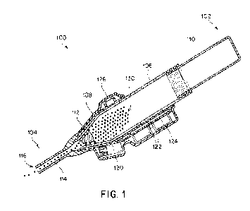
[0043] FIGs. 1-2B depict one embodiment of a vibrational powder
applicator 100.
FIG. 1 is a cross-sectional schematic of the applicator 100. FIG. 2A is a top
view of the
vibrational powder applicator 100, and FIG. 2B is a cross-sectional side view
of the
vibrational powder applicator 100. In this embodiment, the applicator 100
includes a
proximal end 102 associated with a powder storage chamber 110 and a distal end
104
associated with an outlet 116 formed on a distal portion of the applicator.
The powder storage
chamber 110 is configured to store a powder 130 disposed therein, which may
include a
therapeutic powder such as a hemostatic powder or other appropriate powder.
The powder
storage chamber 110 may be operatively coupled to a housing 106 of the
applicator 100. In
some embodiments, the storage chamber 110 may be removably coupled to the
housing 106
(e.g., using a threaded interface, fasteners, press fits, or any other
suitable coupling). In some
embodiments, the storage chamber 110 may be fixedly coupled to the housing 106
such that
it may not be removed. In yet other embodiments, the chamber may be integrally
formed in a
portion of the housing such that the chamber is fully formed within the
housing of the
applicator. In the depicted embodiment, an overall powder storage chamber
corresponding to
the internal volume formed within the housing and the removable portion of the
chamber may
be provided. Regardless of the specific construction, the resulting powder
storage chamber
may include the powder disposed therein for subsequent dispensing by the
applicator. A
distal portion of the housing 106 may include one or more components to
restrict the free
flow of powder through the outlet of the applicator including, for example, a
flow restrictor
112. Powder that flows through a gap between the one or more portions of the
flow restrictor
and the interior surface of the chamber and/or nozzle, or other portion of the
housing, may
flow through a nozzle 114 before exiting the applicator through the outlet
116. In some
embodiments, an applicator 100 may include a sleeve 108 that surrounds at
least a portion of
the housing 106. The sleeve 108 may be configured to provide at least partial
vibration
isolation between the housing 106 and a user's hand. In some instances, the
sleeve may also
CA 03215579 2023-09-28
WO 2022/211804 PCT/US2021/025139
- 15 -
provide an ergonomic grip for the user. The sleeve 108 may additionally house
driving
components, such as an actuator 120, one or more batteries 122, a PCB 124,
and/or an
activation button 126. As discussed above, the actuator 120 may be configured
to vibrate the
powder 130 to fluidize the powder and allow the powder to flow out of the
outlet 116. For
example, the actuator 120 may include a motor configured to rotate an
eccentric mass. In
some embodiments, the button 126 may be configured to activate the actuator
120. In some
embodiments, the button 126 may be configured to actuate both the actuator 120
and an
active flow control element, as described in greater detail below in reference
to FIG. 5. It
should be understood that while the one or more actuators of the applicator
have been shown
as being disposed between the outer sleeve and applicator in the depicted
embodiment, other
constructions are contemplated. For example, the actuator may be operatively
coupled with
the housing of the applicator in any appropriate fashion including both
direct, and indirect,
connections with any desired portion of the applicator housing such that the
one or more
actuators are capable of applying vibrations to the housing of the applicator.
[0044] FIGs. 3A-4D depict different embodiments of a flow restrictor 200.
FIG. 3A is
a cross-sectional back view of one embodiment of a flow restrictor 200. The
flow restrictor
200 may include a body 202 disposed in a central portion of the chamber and
flow path and a
plurality of fins 204 extending from the central body 202. However,
embodiments in which
the body is not disposed in a central portion of the chamber are also
contemplated. In the
embodiment of the figure, the fins 204 extend radially outwards from the
central body 202.
Depending on the embodiment, the fins may either have a gap between the fins
and the
interior surface 256a of the housing 256 of the applicator 250 or the fins may
contact the
interior surface of the housing. In either case, the fins 204 form at least
one, and in some
instances, a plurality of gaps 206 between the flow restrictor and the
interior surface of the
powder storage chamber formed in the housing to allow flow of the powder past
the flow
restrictor to the nozzle and outlet when the powder is fluidized.
[0045] Note that in the back view of FIG. 3A, it may be difficult to see
the interface
of the fins 204 with the interior surface 256a of the housing 256 due to the
tapered geometry
of a portion of the distal end 254 of the applicator 250. FIG. 3B is a cross-
sectional side view
of a distal end 254 of one embodiment of a vibrational powder applicator 250
that shows
where a flow restrictor 200 may be disposed, taken along line 3B-3B shown in
FIG. 3A.
CA 03215579 2023-09-28
WO 2022/211804 PCT/US2021/025139
- 16 -
Consistent with FIG. 3A, FIG. 3B shows a fin 204 along a top center of the
flow restrictor
200 and a gap 206 along a bottom center of the flow restrictor 200. As can be
seen in FIG.
3B, the fin 204 extends up to and contacts the interior surface 256a of the
housing 256 of the
applicator 250. However, as noted above, embodiments in which the one or more
fins do not
contact the interior surface of the housing are also contemplated.
[0046] FIGs. 4A-4D are cross-sectional views of different embodiments of
flow
restrictors with different numbers of fins. FIG. 4A shows an embodiment of a
flow restrictor
200a that includes six fins. FIG. 4B shows an embodiment of a flow restrictor
200b that
includes nine fins. FIG. 4C shows an embodiment of a flow restrictor 200c that
includes
twelve fins. FIG. 4D shows an embodiment of a flow restrictor 200d that
includes sixteen
fins. While four specific examples of flow restrictors with different numbers
of fins have
been provided in FIGs. 4A-4D, it should be appreciated that a flow restrictor
200 may include
any suitable number of fins, as the disclosure is not limited in this regard.
Additionally,
without wishing to be bound by theory, fewer fins may permit the passage of
larger powder
particles for the same gap size between the corresponding body and interior
surface of the
housing as compared to a larger number of fins which may permit
correspondingly smaller
particles to flow past the flow restrictor. Accordingly, the usage of
different flow restrictors
with either different gap sizes and/or numbers of fins may permit the usage of
different size
powders with the same overall applicator design.
[0047] FIG. 5 is a cross-sectional side view of one embodiment of a
vibrational
powder applicator 300 that includes a valve 312 configured to restrict the
flow of powder
through the applicator when it is in the closed configuration. For example,
this may be
desirable when some amount of powder may leak out from the device when
oriented
vertically downwards either due to powder size, outlet size, or other
appropriate
considerations. In the depicted embodiment, the applicator 300 includes a
proximal end 302
associated with a powder storage chamber 310 operatively coupled to a housing
306, and a
distal end 304 associated with a nozzle 314 and an outlet 316. The valve 312
is disposed
between the powder storage chamber 310 and the outlet 316. In the embodiment
of the figure,
the valve 312 includes a moveable gate 340 operatively coupled to a spring 342
and a button
344. When a user depresses the button 344, the gate 340 moves to align an
aperture in the
gate with a conduit through which the powder is configured to flow. When the
user releases
CA 03215579 2023-09-28
WO 2022/211804 PCT/US2021/025139
- 17 -
the button 344, the spring 342 returns the gate 340 to its default position in
which the aperture
is not aligned with the conduit, thereby preventing flow. Thus, the valve may
selectively
permit and prevent the flow of powder through the nozzle and outlet based on
whether or not
the valve is in the open or closed configuration. While a specific gate valve
has been shown
in the figure, it should be understood that any appropriate type of valve
capable of selectively
restricting the flow of a powder through the nozzle and outlet of an
applicator may be used as
mentioned previously as the disclosure is not limited in this fashion.
[0048] While the present teachings have been described in conjunction
with various
embodiments and examples, it is not intended that the present teachings be
limited to such
embodiments or examples. On the contrary, the present teachings encompass
various
alternatives, modifications, and equivalents, as will be appreciated by those
of skill in the art.
Accordingly, the foregoing description and drawings are by way of example
only.
[0049] The embodiments described herein may be embodied as a method, of
which
an example has been provided. The acts performed as part of the method may be
ordered in
any suitable way. Accordingly, embodiments may be constructed in which acts
are
performed in an order different than illustrated, which may include performing
some acts
simultaneously, even though shown as sequential acts in illustrative
embodiments.
[0050] Further, some actions are described as taken by a "user." It
should be
appreciated that a "user" need not be a single individual, and that in some
embodiments,
actions attributable to a "user" may be performed by a team of individuals
and/or an
individual in combination with computer-assisted tools or other mechanisms.
[0051] The present disclosure at times uses terms denoting relative
positions such as
"below" and/or "above". It should be appreciated that these relative terms are
used relative to
a local direction of gravity. For example, a first object is understood to be
"below" a second
object if the second object moves toward the first object along a
gravitational axis when acted
upon solely by a gravitational force. It should be appreciated that an object
that is "above" or
"below" another object need not be "directly above" or "directly below" the
other object. For
example, if the local direction of gravity is aligned with a vertical
direction, one object may
be offset horizontally (i.e., perpendicularly from the gravitational axis)
from another object
and still be "above" or "below" the other object.