Note: Descriptions are shown in the official language in which they were submitted.
CA 03216044 2023-10-04
WO 2022/217333
PCT/CA2022/000016
TITLE
Safety seat for emergency vehicles
FIELD
[0001] The present disclosure relates to safety seats. More
specifically, the present disclosure is concerned with a safety seat for
emergency
vehicles.
BACKGROUND
[0002] Safety seats for emergency vehicles and, more particularly,
safety seats adapted for installation in an ambulance or other emergency
vehicle
to enable medical attendants to safely perform emergency medical services on
a patient while the vehicle is in motion are known in the art.
[0003] These safety seats are generally designed to withstand
important acceleration forces since they must protect the medical attendant
seated therein should a road accident occur. Accordingly, the structure of
these
seats is often bulky, and yield a big bulky seat that is heavy.
[0004] Another problem with conventional safety seats for emergency
vehicles in the size and shape of the seat portion of the safety seat that is
generally not suited for medical attendants that often have to lean forward to
perform medical services.
BRIEF DESCRIPTION OF THE DRAWINGS
[0005] In the appended drawings:
CA 03216044 2023-10-04
WO 2022/217333
PCT/CA2022/000016
2
[0006] Figure 1 is a perspective view of an assembled safety seat
for
emergency vehicle according to an illustrative embodiment;
[0007] Figure 2 is a perspective view similar to Figure 1 but
showing
the safety seat structure in dashed lines;
[0008] Figure 3 is a side elevational view of the safety seat of
Figure
1;
[0009] Figure 4 is a perspective view of the safety seat structure
according to a first illustrative embodiment;
[0010] Figure 5 is a sectional view taken along line 5-5 of Figure
4;
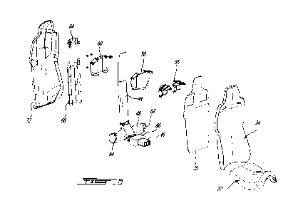
[0011] Figure 6 is an exploded view of the safety seat of Figure 1;
[0012] Figure 7 is a perspective view of the column and transversal
elements of a safety seat structure according to a second illustrative
embodiment;
[0013] Figure 8 a sectional view taken along line 8-8 of Figure 7;
[0014] Figure 9 is a partially exploded view of the safety seat
structure
of Figure 7;
[0015] Figure 10 is a perspective view of a safety seat structure
according to a third illustrative embodiment;
CA 03216044 2023-10-04
WO 2022/217333
PCT/CA2022/000016
3
[0016] Figure 11
is a perspective view of the column of a safety seat
structure according to a fourth illustrative embodiment; and
[0017] Figure 12
is a perspective view of the column of a safety seat
structure according to a fifth illustrative embodiment;
[0018] Figure 13
is a front perspective view of a safety seat structure
according to a sixth illustrative embodiment;
[0019] Figure 14
is a sectional view taken along line 14-14 of
Figure 13;
[0020] Figure 15
is a rear perspective view of the safety seat
structure of Figure 13;
[0021] Figure 16
is a perspective view illustrating the seat to base
connecting mechanism in a locked configuration; and
(0022] Figure 17
is a perspective view illustrating the seat to base
connecting mechanism in an unlocked configuration.
DETAILED DESCRIPTION
[0023] The use
of the word "a" or "an" when used in conjunction with
the term "comprising" in the claims and/or the specification may mean "one",
but
it is also consistent with the meaning of "one or more", "at least one", and
"one
or more than one". Similarly, the word "another" may mean at least a second or
more.
CA 03216044 2023-10-04
WO 2022/217333
PCT/CA2022/000016
4
100241 As used in this specification and claim(s), the words
"comprising" (and any form of comprising, such as "comprise" and "comprises"),
"having" (and any form of having, such as "have" and "has"), "including" (and
any
form of including, such as "include" and "includes") or "containing" (and any
form
of containing, such as "contain" and "contains"), are inclusive or open-ended
and
do not exclude additional, unrecited elements or process steps.
[0025] In the present specification and in the appended claims,
various terminology which is directional, geometrical and/or spatial in nature
such as "longitudinal", "horizontal", "front", rear", "upwardly",
"downwardly", etc.
is used. It is to be understood that such terminology is used for ease of
description and in a relative sense only and is not to be taken in any way as
a
limitation upon the scope of the present disclosure.
[0026] The expression "connected" should be construed herein and
in the appended claims broadly so as to include any cooperative or passive
association between mechanical parts or components. For example, such parts
may be assembled together by direct coupling, or indirectly coupled using
further
parts.
[0027] Other objects, advantages and features of the safety seat for
emergency vehicles will become apparent upon reading of the following non-
restrictive description of illustrative embodiments thereof, given by way of
example only with reference to the accompanying drawings.
[0028] Generally stated, an illustrative embodiment is concerned
with
a safety seat for emergency vehicles including a structure including a
generally
L-shaped column defining a backrest structure and a seat structure. A
transversal element is provided at a junction of the backrest structure and
the
seat structure and a strengthening bracket is connected to both the backrest
CA 03216044 2023-10-04
WO 2022/217333
PCT/CA2022/000016
structure and the seat structure. The strengthening bracket may be integral or
separated from both the backrest structure and the seat structure. The safety
seat includes a seat mounted to the seat structure and a backrest mounted to
the backrest structure.
[0029] Turning now to Figures 1 to 6 of the appended figures, a
safety
seat 20 for emergency vehicles according to a first illustrative embodiment
will
be described.
[0030] As can be better seen from Figures 1 to 3, the safety seat 20
includes a saddle-type seat 22 and a backrest 24. To secure these elements to
one another and eventually to a floor base (not shown), a safety seat
structure
26 is shown in dashed lines in Figure 2.
[0031] The saddle-type seat 22 has a generally inverted U-shaped
front profile, therefore sloping the lateral sides 28 and 30 lower than the
middle
32 of the seat. Furthermore, a horn 34 centrally provided in the front of the
seat
place the legs of the occupant in a stable slightly spread configuration.
Paired
with the sloping lateral sides 28 and 30, the horn 34 places the occupant in a
stable position where the occupant can easily bend forward to perform
emergency medical services on a patient while maintaining a stable position.
[0032] The backrest 24 includes a headrest portion 36 provided with
safety belt passages 38, 40 on either side thereof.
[0033] Turning now to Figures 4 to 6 of the appended drawings, the
safety seat structure 26 according to a first illustrative embodiment will be
described.
CA 03216044 2023-10-04
WO 2022/217333
PCT/CA2022/000016
6
[0034] The safety seat structure 26 includes a generally L-shaped
column 42 defined by a backrest structure 44 integrated with a seat structure
46.
A transversal element 48, here in a cylindrical form, is provided at the
junction of
the backrest and seat structures 44 and 46. Strengthening brackets 50 and 52,
separate from the structures 44 and 46, reinforce the connection between these
structures as will be described hereinbelow.
[0035] The safety seat structure 26 also includes a safety belt
assembly 54 mounted to the column 42 in the vicinity of the headrest 36.
Conventionally, the safety belt assembly 54 includes two belt rollers 56
mounted
to either sides of the column 42 via a front bracket 58 and a rear bracket 60.
Of
course, fasteners are used to mount the brackets 58 and 60 to one another.
[0036] The safety belt assembly also includes an abdominal part (not
shown) that is attached to the end caps 62, 64 of the transversal elements 48
that are tear-drop shaped and include an aperture to fasten the bottom part of
the safety belt assembly.
[0037] As will be understood by one skilled in the art, the end caps
62, 64 could be replaced by supplemental belt rollers (not shown) to yield a
four
point harness.
[0038] A seat mounting bracket 66 is mounted to the seat structure
46 and is so configured to receive the seat 22 thereon. The bracket 66 is also
used to mount the safety seat 20 to a seat base (not shown).
[0039] A backrest mounting bracket assembly configured to allow the
backrest 24 to be mounted to the backrest structure 44 includes rear brackets
68, 69 and a front backrest support 70. Once these elements are fastened to
CA 03216044 2023-10-04
WO 2022/217333
PCT/CA2022/000016
7
the backrest structure 44, the backrest 24 can be secured thereto. It is to be
noted that a back cover 72 is mounted to the backrest 24 to hide the structure
and to provide a smooth back surface.
[0040] Turning now more specifically to Figure 5 of the appended
drawings, the L-shaped column 42 is defined by a generally rectangular tubing
74. It has been found that 6061-T6 aluminum is adequate for this tubing. Of
course, other materials could be used.
[0041] The tubing 74 is filled with alternated layers of carbon
fiber
sheets 76 and of corelite foam 78, from the company Corelite Composites.
These layers 76 and 78 are snugly inserted in the tubing 74 to thereby
increase
the stiffness thereof by filling any gap therein.
[0042] One skilled in the art will understand that the carbon fiber
layer
76 could be replaced by other structuring materials such as, for example
aluminum 7075-T6.
[0043] Similarly, the structural foam layer 78 could be made from
other gap filling materials.
[0044] The generally rectangular tubing 74 includes a front wall
80, a
rear wall 82 and lateral walls 84. As can be seen from Figure 5, portions of
the
front wall 80 and of the lateral walls 84 are removed at the junction of the
backrest
structure 44 to the seat structure 46 to allow passage of the transversal
element
48. The rear wall 82 is curved to fit around the element 48. The transversal
element 48 is made of the same material as the rectangular tubing 74 and
includes a tube of corelite foam 86 therein to increase its stiffness.
CA 03216044 2023-10-04
WO 2022/217333
PCT/CA2022/000016
8
[0045] One skilled in the art will understand that the front wall
80 can
be welded to the transversal element 48 at junctions thereof.
[0046] A shallow circumferential channel (not shown) can be done on
the outer surface of the transversal element 48 to accept the lateral walls 84
and
therefore correctly position the transversal element 48 with respect to the
column
42 during assembly thereof.
[0047] A front strengthening bracket 50 and two lateral
strengthening
brackets 52 (only one shown in Figure 4) are provided to maintain the
orientation
of the backrest structure 44 with respect to the seat structure 46. These
brackets
are made of the same material as the rest of the structure and are mounted via
regular fasteners. Of course, these brackets 50 and 52 could also be welded or
otherwise securely mounted to the structure.
[0048] One skilled in the art will also understand that the
strengthening brackets 50 and 52 could be integral, i.e., made from one folded
piece.
[0049] Having a column-type structure to support the seat and backrest is
interesting for many reasons: it allows energy absorption from different
directions; it can absorb vibrations generated by the movement of the vehicle;
and it is lighter than conventional safety seat structures.
[0050] Turning now to Figures 7 to 9 of the appended drawings, a
safety seat structure 100 according to a second illustrative embodiment will
be
described. It is to be noted that for concision purpose, only the differences
between the structure 100 and the structure 26 of Figures 1 to 6 will be
discussed
hereinbelow.
CA 03216044 2023-10-04
WO 2022/217333
PCT/CA2022/000016
9
[0051] Generally stated, the structure 100 has a generally L-shaped
column 101 that lacks the generally rectangular tube configuration of the
structure 26 described hereinabove. The alternate layers of corelite 102 and
of
carbon fiber 104 forming the column 101 are bonded to one another and lateral
layers of aluminum 106 are provided. It has been found that aluminum 7075T6
has been found suitable to form the layers 106. Of course, other materials
could
be used.
[0052] As can be seen from Figure 8, the transversal element 48 of
Figures 1 to 6 has been replaced by two transversal elements 108, 110 that are
mounted to the column 101 using conventional fasteners 112 going through the
column 101.
[0053] Returning to Figure 7, one skilled in the art will understand
that
the junction of the backrest structure 103 to the seat structure 105 includes
an
integral bracket 107 to stiffen the column 101 by providing more material at
the
junction thereof.
[0054] Figure 9 shows the safety seat structure 100 in an exploded
view.
[0055] Turning now to Figure 10 of the appended drawings, a safety
seat structure 200 according to a third illustrative embodiment will be
described.
Since the structure 200 is very similar to the structure 100 illustrated in
Figures
7 to 9, only the differences thereof will be described hereinbelow, for
concision
purpose.
[0056] Generally stated the main difference is that the structure 200
includes guy straps 202 and 204 respectively provided between the lateral
CA 03216044 2023-10-04
WO 2022/217333
PCT/CA2022/000016
elements 208, 210 and the safety belt assembly 212. These straps 202, 204
help strengthening the backrest structure in case of lateral impacts.
[0057] Of course, the number, position and nature of the straps can
be modified.
[0058] Turning now to Figure 11 of the appended drawings a
generally L-shaped column 300 according to a fourth illustrative embodiment
will
be described.
[0059] The column 300 is entirely made of aluminum plates. A folded
front plate 302 and a folded rear plate 304 are maintained in a spaced apart
relationship by three L-shaped plates 306. The front and back plates 302 and
304 are provided with oblong apertures 308 while the L-shaped plates 306
include corresponding tabs 310 so positioned and configured as to enter the
apertures 308 to allow welding of these parts together (see welds 311).
[0060] Each of the L-shaped plates 306 include a circular aperture
312 allowing the transversal element (not shown) therethrough and other oblong
apertures 314 provided to reduce the overall weight of the column 300.
[0061] It is to be noted that while three L-shaped plates 306 are
illustrated herein, this number could be changed.
[0062] It has been found that 7075T6 type aluminum is an adequate
material to make the L-shaped column 300.
[0063] As will be understood by one skilled in the angled portion of
the front plate 302 may be viewed as an integral strengthening bracket since
it
CA 03216044 2023-10-04
WO 2022/217333
PCT/CA2022/000016
11
strengthens the interconnection of the backrest structure to the seat
structure.
The conforming shape of the L-shaped plates 306 also serve as strengtheners
between the backrest structure and the seat structure.
[0064] Turning to Figure 12 of the appended drawings a generally L-
shaped column 400 according to a fifth illustrative embodiment will be
described.
[0065] The main difference between the column 400 and the column
300 of Figure 11 is the shape and number of apertures of the L-shaped plates
402. Indeed, the apertures 404 are generally triangular and more numerous.
The column 400 could be viewed as a triple 1-beam.
[0066] Furthermore, the column 400 does not include a circular
aperture allowing the transversal element (not shown) therethrough. When such
a column is used separate transversal elements such as the elements 108 and
110 of Figure 8 are used.
[0067] Again, as will be understood by one skilled in the art, the
angled portion of the front plate of the column 400 and the shape of the
plates
402 may be viewed as an integral strengthening brackets since they strengthen
the interconnection of the back structure to the seat structure.
[0068] Turning now to Figures 13 to 18, a safety seat structure 500
according to a sixth illustrative embodiment will be described. Since this
structure 500 is similar to the structures described hereinabove, and for
concision
purpose, only the differences will be described hereinbelow.
[0069] Generally stated, the structure 500 has a column 502 similar
to the column 300 of Figure 11 but includes supplemental separate lateral
CA 03216044 2023-10-04
WO 2022/217333
PCT/CA2022/000016
12
strengthening brackets 504 to strengthen the junction between the backrest
structure 506 and the seat structure 508. These brackets 504 are mounted to
the column 300 via conventional fasteners but could also be welded thereto.
[0070] The backrest structure includes two belt rollers 510, 512
that
are provided lower than the headrest portion 514. The belts 516 and 518 pass
through respective guiding elements 520, 522 to allow the free ends thereof to
be in the vicinity of the headrest portion 514 when not in use.
[0071] The safety seat structure 500 also includes two supplemental
belt rollers 524, 526 respectively mounted to transversal elements 528, 530.
As
can be better seen from Figure 14, the transversal elements 528 and 530 are
secured to the column via fasteners 532 (only two shown) going through the
brackets 504 and the column 502. Some of the fasteners 532 also secure the
rollers 524 and 526 thereto.
[0072] One skilled in the art will understand that while the four
belts
shown herein are provided with seat belt clips such as 534, one of the belts
could
advantageously be provided with a seat belt buckle assembly (not shown)
configured to receive the clips from the other three belts.
[0073] To increase the available movements of the emergency worker
using the seat mounted to the safety seat structure 500, a selectively
actuated
sliding mechanism 536 is used to mount the structure 500 to a seat base (not
shown) usually fixedly mounted to the floor of the emergency vehicle (also not
shown).
[0074] More specifically, the sliding mechanism 536 is mounted to
the
seat structure 508 so as to allow longitudinal movements of the seat. The
sliding
CA 03216044 2023-10-04
WO 2022/217333
PCT/CA2022/000016
13
mechanism 536 includes a body 538 mounted to the seat structure 508 via two
longitudinal rods 540, 542, as can be better seen from Figure 14. Of course,
bearings, such as 544, are provided between the body 538 and the rods 540,
542. The rods 540, 542 are mounted to the seat structure 508 via brackets 544-
550.
[0075] As can be better seen from Figure 15, a post 552 is mounted
to the underside of the body 538 to mount the seat structure 500 to the seat
base
(not shown).
[0076] The sliding mechanism 536 also includes a locking
arrangement 554 to prevent sliding movements by default and to selectively
allow movements when the user allows it.
[0077] As can be better seen from Figures 16 and 17, the locking
arrangement 554 includes a pivotable rod 556 mounted to and between the
brackets 546 and 550. The rod 556 includes equally spaced projections 558
while the body 538 includes corresponding projection receiving channels 560.
[0078] Figure 16 illustrates the locking arrangement 554 in its
locked
position, i.e., when the projections 558 are positioned in the channels 560.
When
it this position, the body 538 is mechanically prevented from longitudinally
slide
on the rods 540, 542.
[0079] A user actuated mechanical linkage assembly 562 is provided
to pivot the rod 556 so as to momentarily release the projections 558 from the
channels 560. The mechanical linkage assembly 562 includes a Bowden cable
564 mounted between a user accessible handle 566 and the pivoting rod 556.
As can be better seen from Figure 14, the housing of the Bowden cable 564 is
CA 03216044 2023-10-04
WO 2022/217333
PCT/CA2022/000016
14
mounted between a first bracket 568 provided in the vicinity of the handle 556
and a second bracket 570 mounted to the bracket 546.
[0080] One end of the inner cable 571 is mounted to the handle 566
while the other end thereof is partially rolled about the pivoting rod 556.
[0081] Accordingly, one skilled in the art that by pulling on the
handle
566 (se arrow 572 in Figure 17) the rod 556 is pivoted (see arrow 574) to
thereby
release the projections 558 from the channels 560 and thereby place the
locking
arrangement in an unlocked position and allow the body 538 to slide on the
rods
540, 542.
[0082] While not shown herein, the pivoting rod 556 includes a
biasing
mechanism that forces the rod 556 towards its locked position when the handle
566 is released by the user. This biasing mechanism could, for example,
include
springs provided between the rod 556 and the brackets 546, 550.
[0083] One skilled in the art will notice that the spacing between
the
channels 560 is half the spacing between the projections 558 to allow more
locking positions.
[0084] The safety seat structure 500 also includes first and second
momentary switches 576 and 578 that can be used to control the seat-base
mechanism (not shown).
[0085] One skilled in the art will understand that features of the
various above-described embodiments could be provided on other
embodiments. As non -limiting examples, the guy-straps of the column 200
CA 03216044 2023-10-04
WO 2022/217333
PCT/CA2022/000016
and/or the sliding mechanism 536 could be provided on any of the other
embodiments described herein.
[0086] As will easily be understood by one skilled in the art, the
type
of seats that can be mounted to the safety seat structures described
hereinabove
can be different than the saddle-type seat 22 shown in Figures 1 to 6.
[0087] It is to be understood that the safety seat for emergency
vehicles is not limited in its application to the details of construction and
parts
illustrated in the accompanying drawings and described hereinabove. The safety
seat for emergency vehicles is capable of other embodiments and of being
practiced in various ways. It is also to be understood that the phraseology or
terminology used herein is for the purpose of description and not limitation.
Hence, although the safety seat for emergency vehicles has been described
hereinabove by way of illustrative embodiments thereof, it can be modified,
without departing from the spirit, scope and nature thereof.