Note: Descriptions are shown in the official language in which they were submitted.
WO 2022/232198
PCT/US2022/026425
1
MEDICAMENT CONTAINER
FIELD
100011 Disclosed embodiments are related to medicament
containers and related
methods of use.
BACKGROUND
100021 Medicament containers are used to hold therapeutic fluid.
Such therapeutic
fluids may be delivered to a patient via parenteral delivery (e.g.
subcutaneous injection,
intramuscular injection, intravenous injection), via enteral delivery (e.g. by
a gastric feeding
tube or a duodenal feeding tube), or by any other suitable route of
administration.
Medicament containers may be configured to controllably release the
therapeutic fluid for
delivery into the patient. Health providers typically designate a prescribed
amount of
medication to be administered to the patient.
SUMMARY
100031 In some embodiments, a medicament container comprises a
sidewall, a spout
coupled to the sidewall, and an extension coupled to the spout. The sidewall
may at least
partially define an interior volume of the medicament container. The spout may
be configured
for outflow of medicament from the interior volume of the medicament
container. The
extension may be disposed inside the interior volume of the medicament
container. The
sidewall may have greater flexibility than the extension such that the
medicament container
has a collapsed state when empty and an expanded state when full. The sidewall
may be
configured to move as the medicament flows out of the interior volume of the
medicament
container through the spout. A height of the extension measured along a
central axis of the
spout may be at least a fourth of the sidewall height, measured along a
dimension parallel to
the central axis of the spout when the medicament container is in the expanded
state.
100041 In some embodiments, a medicament container comprises a
sidewall, a spout
coupled to the sidewall, and an extension coupled to the spout. The sidewall
may at least
partially define an interior volume of the medicament container. The spout may
be configured
for outflow of medicament from the interior volume of the medicament
container. The
CA 03216326 2023- 10- 20
WO 2022/232198
PCT/US2022/026425
2
extension may be disposed inside the interior volume of the medicament
container. The
sidewall may have greater flexibility than the extension such that the
medicament container
has a collapsed state when empty and an expanded state when full. The sidewall
may be
configured to move as the medicament flows out of the interior volume of the
medicament
container through the spout. The extension may comprise a first end and a
second end,
wherein the first end is closer to the spout than the second end is to the
spout. A cross-
sectional area of the extension measured normal to a central axis of the spout
may be greater
at the first end than at the second end, wherein the central axis may be
parallel to an outflow
direction through the spout.
[0005] It should be appreciated that the foregoing concepts, and
additional concepts
discussed below, may be arranged in any suitable combination, as the present
disclosure is
not limited in this respect. Further, other advantages and novel features of
the present
disclosure will become apparent from the following detailed description of
various non-
limiting embodiments when considered in conjunction with the accompanying
figures.
BRIEF DESCRIPTION OF DRAWINGS
[0006] The accompanying drawings are not intended to be drawn to
scale. In the
drawings, each identical or nearly identical component that is illustrated in
various figures
may be represented by a like numeral. For purposes of clarity, not every
component may be
labeled in every drawing. In the drawings:
[0007] FIG. 1 is a perspective top view of one embodiment of a
medicament
container;
[0008] FIG. 2 is a front view of the medicament container of
FIG. 1;
[0009] FIG. 3 is a front view of another embodiment of a
medicament container;
[0010] FIG. 4 is a perspective front view of yet another
embodiment of a medicament
container;
[0011] FIGs. 5A-5C are a series of perspective cross-sectional
views of the
medicament container of FIG 4 taken along A-A, B-B, and C-C respectively;
[0012] FIG. 6A is a cross-sectional view of the medicament
container of FIG. 4 taken
along D-D;
100131 FIG. 6B is a right side view of the medicament container
of FIG. 4;
CA 03216326 2023- 10- 20
WO 2022/232198
PCT/ITS2022/026425
3
[0014] FIG. 7A is a perspective top view of yet another
embodiment of a medicament
container;
[0015] FIG. 7B is a front view of the extension of the
medicament container of FIG.
7A;
[0016] FIG. 8A is a front view of yet another embodiment of a
medicament container;
[0017] FIG. 8B is a perspective top view of the spout and
extension of the
medicament container of FIG. 8A;
[0018] FIG. 8C is a right side view of the spout and extension
of the medicament
container of FIG. 8A;
[0019] FIG. 9A is a perspective top view of yet another
embodiment of a medicament
container;
[0020] FIG. 9B is a cross-sectional view of the medicament
container of FIG. 9A
taken along F-F;
[0021] FIG. 9C is a cross-sectional view of the medicament
container of FIG. 9A
taken along G-G;
[0022] FIG. 10 is a perspective top view of yet another
embodiment of a medicament
container;
[0023] FIG. 11 is a front view of yet another embodiment of a
medicament container;
and
[0024] FIG. 12 is a front view of yet another embodiment of a
medicament container.
DETAILED DESCRIPTION
[0025] It should be understood that aspects are described herein
with reference to
certain illustrative embodiments and the figures. The illustrative embodiments
described
herein are not necessarily intended to show all aspects, but rather are used
to describe a few
illustrative embodiments. Thus, aspects are not intended to be construed
narrowly in view of
the illustrative embodiments. In addition, it should be understood that
certain features
disclosed herein might be used alone or in any suitable combination with other
features.
[0026] Medicament containers may be arranged to move from an
expanded state,
wherein the container is configured to hold a fluid, to a collapsed state,
wherein at least a
CA 03216326 2023- 10- 20
WO 2022/232198
PCT/ITS2022/026425
4
portion of the fluid has been withdrawn from the container. In some
embodiments, the
movement between the two states may be enabled by flexibility of the
container's sidewalls.
100271 With conventional containers having flexible sidewalls,
the flexible sidewalls
(or portions of the sidewalls) may sometimes collapse prior to complete
withdrawal of all
fluid in the container. When the sidewalls collapse during the withdrawal of
fluid from these
conventional containers, it may be challenging to extract the remaining volume
of fluid from
the container as the fluid may be trapped between or behind collapsed portions
of the
container. As a result of premature or undesirable collapse of the sidewalls,
a waste of the
medicament or fluid remaining in the container may result. Thus, the inventors
have
recognized a need for an approach that assists in emptying of flexible-walled
containers and
reduces the likelihood of residual fluid remaining in the container following
collapse of the
sidewalls.
100281 According to one aspect, a medicament container may be
provided with an
extension which extends into an interior volume of the medicament container.
In some
embodiments, a sidewall of the medicament container may at least partially
define the interior
volume of the medicament container. The extension may help to provide
structural support to
the sidewall(s) of the medicament container to prevent premature collapse. In
one
embodiment, the extension is a substantially flat body extending more than a
quarter way, or
more than halfway into the container. The extension may extend from a spout,
through which
fluid may flow in and/or out of the container. In some embodiments, both the
spout and the
extension may include coaxial passages to direct flow into and/or out of the
container. In
some embodiments, the extension may include grooves distributed on the surface
of the
extension to, e.g., guide fluid flow to the passage. In some embodiments, the
container may
include ribs extending from the sidewall to prevent premature collapse of the
container and to
direct fluid in the collapsed state toward the spout.
100291 In some embodiments, the medicament container may be
configured and
arranged to contain fluid medication or any other fluid at an expanded state.
Exemplary fluid
medications contained in the medicament container may include one or more
therapeutic
agents such as insulins, insulin analogs such as insulin lispro or insulin
glargine, insulin
derivatives, GLP-1 receptor agonists such as dulaglutide or liraglutide,
glucagon, glucagon
analogs, glucagon derivatives, gastric inhibitory polypeptide (GIP), GIP
analogs, GIP
CA 03216326 2023- 10- 20
WO 2022/232198
PCT/ITS2022/026425
derivatives, combined GIP/GLP-1 agonists such as tirzepatide, oxyntomodulin
analogs,
oxyntomodulin derivatives, therapeutic antibodies. The therapeutic agent may
be formulated
with one or more excipients. In some embodiments, the container may contain
another
suitable fluid or a soft material, such as baby food or confectionary
products, as the current
disclosure is not so limited. The spout may be configured and arranged to be
in fluid
communication with the volume of the medicament container.
100301 In some embodiments, the medicament container includes a
sidewall and a
spout. The sidewall may have a greater flexibility than the extension such
that the
medicament container has a collapsed state when empty and an expanded state
when full.
100311 In some embodiments, the sidewall includes a single
flexible sheet folded or
otherwise arranged to create a container capable of containing fluid at an
expanded state. In
these embodiments, the periphery of the folded flexible sheet may be joined
together using
any suitable method, such as thermal sealing, welding, or adhesive bonding, as
the present
disclosure is not so limited.
100321 In some embodiments, the sidewall includes a plurality of
flexible films
capable of being reconfigured from an expanded state to a collapsed state
while fluid is
extracted out of the container through the spout. In some embodiments, the
plurality of
flexible films are capable of being reconfigured from a collapsed state to an
expanded state
while fluid is inserted into the container, e.g. through the spout, or through
a separate inlet. In
these embodiments, the plurality of flexible films, for example two flexible
films, are joined
at the periphery of the container using any suitable method, such as thermal
sealing, welding,
or adhesive bonding as the present disclosure is not so limited. In some
embodiments, the
sidewall is suitably bonded to the spout, such that the only outlet for the
fluid within the
container is through the spout. In other words, the sidewall is attached to
the spout to prevent
fluid transport out of the container between the sidewall and the spout.
Accordingly, the
extension extends into the container beyond the seam at the periphery of the
sidewall. In
some embodiments, the extension is substantially inside the interior volume.
100331 In some embodiments, the spout includes a passage in
fluid communication
with the interior volume of the container. In some embodiments, the passage is
a cylindrical
opening extending through a portion of the spout, the passage having a
partially or fully
enclosed interior sidewall passing through the extension. However, in other
embodiments, the
CA 03216326 2023- 10- 20
WO 2022/232198
PCT/ITS2022/026425
6
passage may be any suitable geometry to fluidically communicate with the
interior volume of
the container, as the present disclosure is not so limited.
100341 In some embodiments, the medicament container further
includes an extension
coupled to the spout. The extension is disposed inside the interior volume of
the container. In
some embodiments, the extension is configured to prevent premature collapse of
the sidewall
prior to the complete evacuation of the fluid from the container. In these
embodiments, the
extension provides a rigid support for opposing faces of the container in the
collapsed state or
under vacuum, to physically keep the sidewall separated. In some embodiments,
the physical
separation of the sidewall during emptying allows the residual fluid of the
container to flow
out. In some embodiments, the extension is formed as part of or integral to
the spout during
the manufacturing process. In other embodiments, the extension is bonded to
the spout using
any suitable process including thermal sealing, welding, adhesive bonding, or
a mechanical
means as the present disclosure is not so limited.
[0035] In some embodiments, the extension is suitably separate
from the sidewall
such that there may be fluid flow between the sidewall and the extension. In
some
embodiments, the extension extends into the interior volume of the container,
beyond the
point at which the container is sealed to the spout. In some embodiments, the
extension is
only connected to the sidewall through the spout at the expanded state of the
container.
100361 In some embodiments, the extension extends substantially
into the container.
In some embodiments, the extension height, measured along the central axis of
the passage, is
greater than one fourth of the sidewall height, measured along the central
axis of the passage.
In some embodiments, the extension height is greater than one half of the
sidewall height. In
some embodiments, the extension height is less than or equal to one fourth of
the sidewall
height, or any other suitable height as the present disclosure is not so
limited.
100371 In some embodiments, a shape of the body of the extension
provides one or
more benefits. For example, in some embodiments, the extension is shaped to
help to prevent
premature collapse of the sidewall under vacuum while minimizing the volume
taken up by
the extension inside of the container, which may reduce the total volume
available for the
fluid. In some embodiments, an extension may include angled edges and smooth
corners. In
some embodiments, smooth corners reduce the likelihood of damage to the
sidewall when the
extension comes into contact with the sidewall. However, it should be
appreciated that other
CA 03216326 2023- 10- 20
WO 2022/232198
PCT/ITS2022/026425
7
benefits provided by the shape of the extension are possible, and that the
benefits identified
above may not necessarily apply, as this aspect is not so limited.
100381 In some embodiments, the extension includes a first end
at the spout, and a
second end located inside the interior volume of the container distal from the
spout. In some
embodiments, a cross-sectional area of the extension at the first end taken
normal to the
central axis of the passage may be greater than a cross-sectional area of the
extension at the
second end taken normal to the central axis of the passage. In some
embodiments, the
extension is continuously tapered such that the cross-sectional area of the
extension along the
central axis of the passage is continuously decreasing. In other embodiments,
the extension
includes several portions, wherein the cross-sectional area of each portion
along the central
axis of the passage varies based upon the portion. For example, in one
embodiment, the
extension includes a first portion which includes the first end and a second
portion which
includes the second end. In this embodiment, the cross-sectional area of the
first portion is
constant along the central axis, whereas the cross-sectional area of the
second portion
decreases along the central axis moving distally away from the spout. It
should be
appreciated that, in other embodiments, any suitable gradation of the cross-
sectional area of
any portion of the extension may be used as the present disclosure is not so
limited.
100391 In some embodiments, the cross-sectional shape of the
extension is configured
to allow the sidewall to significantly conform to the extension when the
container is under
vacuum. In some embodiments, the extension includes smooth and angled edges.
In some
embodiments, the cross-sectional shape of the extension does not change along
the central
axis of the passage, while in other embodiments, the cross-sectional shape of
the extension
changes along the central axis of the passage. In one embodiment, the cross-
sectional shape
of the extension is hexagonal at the first end, with a pair of opposing faces
configured to be
parallel to the sidewall. The remaining four faces are sufficiently angled to
allow the sidewall
to conform to the extension when the container is under vacuum. In some
embodiments, the
extension is significantly flat and parallel to the sidewall. For example, in
an embodiment
where the cross-sectional shape at the first end is hexagonal, the pair of
opposing faces
parallel to the sidewall are the longest sides of the hexagon. In other
embodiments, the cross-
sectional shape is elliptical, with the minor axis of the ellipse arranged to
be normal to the
sidewall when the container is in the collapsed state. It should be
appreciated that the
CA 03216326 2023- 10- 20
WO 2022/232198
PCT/ITS2022/026425
8
extension may have any suitable cross-sectional shape, including, but not
limited to,
polygonal or lens shaped, as the present disclosure is not so limited.
100401 In some embodiments, the cross-sectional shape of the
extension varies at
different portions of the extension. For example, in one embodiment, the
extension includes a
first portion which includes the first end and a second portion which includes
the second end.
In this example, the cross-sectional shape of the first portion is hexagonal
and the cross-
sectional shape of the second portion is elliptical. In another example, the
cross-sectional
shape of the first portion is hexagonal and the cross-sectional shape of the
second portion is
lens-shaped, e.g. a vesica piscis. At the second end, the extension may taper
to an edge. In
embodiments where the cross-sectional shape at the first end and second end
are different, the
cross-sectional shape of the extension may gradually morph from the shape at
the first end to
the shape at the second end. The variation of cross-sectional shape of the
extension along the
central axis may be linear or non-linear or a combination of the two, as the
present disclosure
is not so limited. While any portion of the extension may include abrupt
changes in either
cross-sectional shape or area, in some embodiments, changes in the extension
geometry may
occur smoothly.
100411 In some embodiments, the extension extends along the
central axis of the
passage into the container. In other embodiments, the extension is a plurality
of bodies
extending at various angles with respect to the central axis of the passage,
as the present
disclosure is not so limited. In some embodiments, the passage splits the
extension into
multiple portions. In some cases, this enables greater outflow of the fluid
from the spout. In
some embodiments, the passage of the extension has a larger cross-sectional
area normal to
the central axis of the passage at the spout, when compared to the passage at
the spout. It
should be appreciated that the extension may be any suitable shape or
plurality of shapes as
the present disclosure is not so limited.
100421 In some embodiments, the passage extends directly from
the spout to the
second end of the extension. In some embodiments, the passage extends from the
spout and
split into multiple passages or channels in the extension. The multiple
passages may be
arranged at various angles with respect to the central axis of the passage in
the spout. The
distribution of a plurality of passages in the extension may fluidically
connect trapped fluid at
CA 03216326 2023- 10- 20
WO 2022/232198
PCT/ITS2022/026425
9
the edges of the extension with the spout, enabling greater outflow of the
fluid from the
spout.
[0043] In some embodiments, the extension is a solid body. In
other embodiments,
the extension includes internal architecture. In these embodiments, the
extension may still
retain structural rigidity, especially when the container is in the collapsed
state, while
reducing the total volumetric footprint of the extension. In some embodiments,
the extension
includes one or more grooves on the surface of the extension. In some
embodiments, the one
or more grooves are angled with respect to the central axis of the passage. In
any embodiment
where the extension includes grooves, the grooves may be in fluid
communication with the
passage at the spout. In some embodiments, the grooves serve as the plurality
of passages of
the extension. In some embodiments, the one or more grooves are angled with
respect to the
central axis of the passage at any angle between 0-90 , for example 0 , 15 ,
30 , 45 , 60 ,
75 , or 90 , as the present disclosure is not so limited.
[0044] In some embodiments, the geometry of the grooves are
arranged to prevent the
sidewall from collapsing within the groove. For example, the grooves may be
large enough to
allow fluid flow to and from the passage but may be small enough to prevent
the sidewall
from caving into the groove and blocking fluid flow. The grooves may be any
suitable shape
to enable fluid flow between the container and the passage, including, but not
limited to,
polygonal or elliptical, as the present disclosure is not so limited.
[0045] In some embodiments, the medicament container includes
one or more ribs
formed on the sidewall to prevent premature collapse of the sidewall prior to
the complete
evacuation of the fluid from the container. In some embodiments, the ribs
project inwardly
into the interior volume of the container. In other embodiments, the ribs
project outwardly
away from the interior volume of the container. In some embodiments, a
combination of ribs
projecting inwardly into the interior volume and ribs projecting outwardly
away from the
interior volume of the container is provided.
[0046] In some embodiments, the ribs are formed on one face of
the sidewall whereas
in other embodiments the ribs are formed on more than one face of the
sidewall.
[0047] In some embodiments, the ribs and the sidewall are
integrally formed as a
single component, such that the single component is formed as one piece at the
same time, for
CA 03216326 2023- 10- 20
WO 2022/232198
PCT/ITS2022/026425
example with hot embossing or molding, although any suitable technique may be
used to
form the ribs.
100481 In other embodiments, the ribs and the sidewall are
formed separately and
subsequently attached to one another. In some embodiments, the ribs are
attached to an
internal surface of the sidewall, such that the ribs are internal to the
interior volume of the
container. In some embodiments, the ribs are attached to an external surface
of the sidewall,
such that the ribs are external to the interior volume of the container.
100491 As discussed herein, in some embodiments, the ribs
project outwardly away
from the interior volume of the container. In some embodiments, the ribs
protrude out of the
plane of the sidewall when the container is in the collapsed state. In some
embodiments, the
ribs are solid such that the rib thickness may be greater than the sidewall
thickness. In some
embodiments, the outwardly projecting ribs have a protruding shape with an
empty void
beneath such that fluid may flow inside the ribs. For example, the projecting
ribs may be
hollow, or may have no fill material beneath the projecting shape. In one
illustrative
embodiment, the cross-section of the ribs has an arched shape without fill
material below the
arch so that an outer surface of the ribs is convex, and an inner surface of
the ribs is concave.
In some embodiments, during emptying of the container, the sidewall collapses
before
collapse of the outwardly projecting ribs. In these embodiments, the ribs
facilitate fluid flow
through their empty voids. In some embodiments, the empty voids extend from
the distal end
of the sidewall to the spout. In some embodiments, the empty voids serve to
increase an
internal volume of the container.
100501 As discussed herein, in some embodiments, the ribs
project inwardly into the
interior volume of the container. In some embodiments, the inwardly projecting
ribs are solid
such that the rib thickness may be greater than the sidewall thickness. In
some embodiments,
the inwardly projecting ribs include an empty void (e.g., are hollow). In some
embodiments,
during emptying of the container, the sidewall collapses before collapse of
the inwardly
projecting ribs. In these embodiments, the inwardly projecting ribs prevent
the sidewall from
collapsing to allow fluid flow between the inwardly projecting ribs from the
distal end of the
sidewall to the spout.
100511 In some embodiments, the ribs have greater rigidity than
the container
sidewall. The rigidity of the ribs in comparison to the container sidewall
allows the ribs to
CA 03216326 2023- 10- 20
WO 2022/232198
PCT/ITS2022/026425
11
provide structural support for the sidewalls during emptying. In some
embodiments, the ribs
have a greater rigidity than the container sidewall due to a greater
thickness. As one example,
in some embodiments, the ribs are thicker than the sidewall in the normal
direction of the
sidewall. In some embodiments, the ribs have a greater rigidity than the
container sidewall
due to geometry. For example, the ribs are formed as a corrugated shape on the
surface of the
sidewall, which may collapse at higher vacuum than the sidewall, remaining
more rigid than
the sidewall at certain pressures at the collapsed state. In some embodiments,
the ribs have a
greater rigidity than the container sidewall due to material properties. For
example, the ribs
are formed of a material having a greater rigidity than a material of the
sidewall. The ribs
may be formed of any material or combination of materials with suitable
mechanical
properties that are compatible with the fluid and applications of the
container. In some
embodiments, the ribs have greater rigidity than the container sidewall due to
any
combination of the above factors.
100521 In some embodiments, the sidewall includes a first or
main rib located
centrally on the sidewall. The main rib may be elongated such that the longest
dimension
spans the container height as described above. While the main rib may be
positioned at any
angle between 0-900, for example 0 , 15 , 30 , 45 , 60 , 75 , 90 with respect
to the central
axis of the passage at the spout, in some embodiments, the longest dimension
of the main rib
is aligned with the central axis of the passage at the spout.
100531 In some embodiments, the container includes an auxiliary
or second rib
extending in a direction at any angle between 0-90 , for example 0 , 15 , 30 ,
45 , 60 , 75 ,
90 with respect to the main rib. In some embodiments, the auxiliary rib is
smaller than the
main rib. In some embodiments, the container includes a plurality of auxiliary
ribs and one
main rib. In an example embodiment, a plurality of short auxiliary ribs is
distributed radially
around a main rib to redirect fluid flow along the main rib and subsequently
the passage. In
another example embodiment, a plurality of short auxiliary ribs lay parallel
to one another
and perpendicular to a plurality of main ribs distributed on the side wall. Of
course, any
suitable combination of auxiliary ribs and main ribs may be used as the
present disclosure is
not so limited.
100541 While any rib may have any suitable shape including, but
not limited to,
polygonal or curved, in some embodiments, the ribs may be substantially curved
and smooth.
CA 03216326 2023- 10- 20
WO 2022/232198
PCT/ITS2022/026425
12
Curvature may help to prevent the accumulation of fluid next to the rib, which
could lead to
incomplete drainage of the container. In some embodiments, the ribs have a
partially
elliptical cross-section taken along a longitudinal axis of the ribs. Of
course, the ribs may
have any suitable cross-sectional geometry to direct fluid flow in the
collapsed state, as the
present disclosure is not so limited.
[0055] In some embodiments, the sidewall includes one or more
portions, wherein at
least a first portion includes the spout and a second portion includes the
distal most edge of
the sidewall relative to the spout. In these embodiments, the one or more ribs
span between
the first portion and the second portion. In some embodiments, the longest
dimension of the
one or more ribs is greater than one fourth of the sidewall height. In some
embodiments, the
longest dimension of the one or more ribs is greater than one third of the
sidewall height. In
some embodiments, the longest dimension of the one or more ribs is greater
than one half of
the sidewall height. In some embodiments, the longest dimension of the one or
more ribs is
greater than three fourths of the sidewall height. It should be appreciated
that the longest
dimension of the one or more ribs may be any suitable size as the current
disclosure is not so
limited.
[0056] In some embodiments, the container includes both an
extension and one or
more ribs. In these embodiments, the one or more ribs are distributed on the
sidewall offset
from the central axis of the passage at the spout. In one example, a container
has an extension
extending along the central axis of the passage and a pair of ribs located on
either side of the
extension. In another example, a container has an extension extending along
the central axis
of the passage and a pair of ribs located perpendicular to the central axis of
the passage. Of
course, any suitable combination of rib location or geometry may be combined
with any
suitable geometry of the extension, as the present disclosure is not so
limited.
[0057] As described herein, in some embodiments, the sidewall is
composed of
materials that enable the container to be reconfigured from an expanded state
to a collapsed
state while fluid is extracted out of the container through the spout, and
from a collapsed state
to an expanded state while fluid is inserted into the container through the
spout. In some
embodiments, the sidewall is composed of one or more layers of polymers
including, but not
limited to, polypropylene (PP), polyethylene (PE), ethylene vinyl alcohol
(EVOH),
polyamide (PA), polychlorotrifluoroethylene (PCTFE), cyclic olefin copolymer
(COC),
CA 03216326 2023- 10- 20
WO 2022/232198
PCT/ITS2022/026425
13
polycarbonate (PC), ethylene vinyl acetate (EVA), polyvinyl chloride (PVC),
polyvinylidene
chloride (PVDC), polystyrene (PS), polyethylene terephthalate (PET),
thermoplastic
elastomer (TPE), polymethyl methacrylate (PMMA), or any other suitable polymer
as the
present disclosure is not so limited.
100581 As described herein, in some embodiments, the spout or
extension is
composed of materials less flexible than the sidewall, such that the spout and
extension do
not move or otherwise be reconfigured while fluid is extracted out of or
inserted into the
container through the spout. In some embodiments, the spout is composed of one
or more
polymers including, but not limited to, polypropylene (PP), cyclic olefin
copolymer (COC),
polym ethyl methacryl ate (PMMA), copolyester (PCTG), polyethylene terephthal
ate (PET),
polycarbonate (PC), polystyrene (PS), high density polyethylene (FIDPE), or
any other
suitable polymer as the present disclosure is not so limited. In some
embodiments, the spout
is composed of a composite material.
10059] Turning to the figures, specific non-limiting embodiments
are described in
further detail. It should be understood that the various systems, components,
features, and
methods described relative to these embodiments may be used either
individually and/or in
any desired combination as the disclosure is not limited to only the specific
embodiments
described herein. For example, while all the embodiments described herein
refer to
medicament containers, the container may be configured for containing any
suitable fluid,
such as a beverage, as the present disclosure is not so limited.
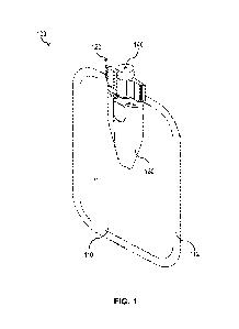
100601 In the exemplary embodiment of FIG. 1, the medicament
container 100
includes a sidewall 110 and a spout 120. The sidewall 110 at least partially
defines an interior
volume V configured to contain medicament or any other fluid when the
medicament
container is in an expanded state. The spout 120 is in fluid communication
with the interior
volume of the medicament container 100.
100611 In the illustrative embodiment of FIG. 1, the sidewall
110 is made up of two
flexible sheets joined together at the periphery by a seam 112. In other
embodiments, the
sidewall may be made of a single flexible sheet folded or otherwise arranged
to create a
container capable of containing fluid at an expanded state, or more than two
flexible sheets,
or any other suitable arrangement.
CA 03216326 2023- 10- 20
WO 2022/232198
PCT/ITS2022/026425
14
100621 The periphery of the sidewall may be joined together at
the seam 112 using
any suitable method, such as thermal sealing, welding, or adhesive bonding as
the present
disclosure is not so limited. In some embodiments, the sidewall is further
joined to the spout
to prevent fluid transport out of the container between the sidewall and the
spout. The
sidewall may be joined to the spout using any suitable method, such as thermal
sealing,
welding, or adhesive bonding as the present disclosure is not so limited.
100631 The spout 120 illustratively includes a passage 140
fluidically connected to the
interior volume of the medicament container 100. In the illustrative
embodiment shown in
FIG. 1, the passage 140 is a cylindrical opening extending through a fully
enclosed portion of
the spout's sidewall.
100641 Medicament container 100 further includes an extension
130 connected to the
spout 120. The extension 130 is positioned within the container 100 between
the sidewall 110
or plurality of sidewalls. As described herein, in some embodiments, the
extension 130 is
separate from the sidewall 110 such that there may be fluid residing and
flowing between the
sidewall 110 and the extension 130 when the container 100 is at the expanded
state. As
shown in FIG. 1, the extension 130 extends into the container 100 beyond the
seam 112
around spout 120. In some embodiments, the extension 130 is substantially
inside the interior
volume V. In the illustrated embodiment of FIG. 1, extension 130 extends to a
central region
of the volume of the container 100, such that its distal end is centrally
located along the width
and height of the container 100. In some embodiments, the extension 130 is
configured to
prevent premature collapse of the sidewall 110 prior to the complete
evacuation of the fluid
from the container 100. In these embodiments, the extension 130 provides a
rigid support for
opposing faces of the container 100 in the collapsed state or when under
vacuum, to
physically keep the sidewall 110 separated. In some embodiments, the physical
separation of
the sidewall 110 during emptying allows the residual fluid in the container
100 to flow out.
As shown in FIG. 1, in some embodiments, the extension 130 is formed as part
of the spout
120 during the manufacturing process. In other embodiments, the extension 130
is bonded to
the spout using any suitable process including thermal sealing, welding,
adhesive bonding, or
a mechanical means as the present disclosure is not so limited.
100651 As shown in FIGS. 2 and 3, the extension 130 extends into
the interior volume
V of the container 100. In some embodiments, the extension height H1, measured
along the
CA 03216326 2023- 10- 20
WO 2022/232198
PCT/ITS2022/026425
central axis AX of the passage 140 (see FIG. 2), is at least one fourth of the
sidewall height
H2, measured along the central axis AX of the passage. In an exemplary
embodiment, as
shown in FIG. 2, the extension height H1 is approximately one half of the
sidewall height H2.
In some embodiments, the extension height HI is greater than one half of the
sidewall height
H2. In an exemplary embodiment, as shown in FIG. 3, the extension height HI is
approximately two thirds of the sidewall height H2. In some embodiments, the
extension
height H1 is less than or equal to one tenth, one ninth, one eighth, one
seventh, one sixth, one
fifth, one fourth, two fifths, one third, one half, three fifths, three
quarters, or four fifths of the
sidewall height H2. In some embodiments, the extension height HI is at least
one tenth, one
ninth, one eighth, one seventh, one sixth, one fifth, one fourth, two fifths,
one third, one half,
three fifths, three quarters, or four fifths of the sidewall height H2, or any
other suitable
height as the present disclosure is not so limited. In some embodiments, the
extension height
H1 is approximately equal to the sidewall height H2. Combinations of the above-
referenced
ranges are also possible. For example, in some embodiments, the extension
height H1 is
between one tenth and four fifths, one tenth and one half, one eight and three
quarters, one
fifth and four fifths, one third and two thirds, or one half and four fifths
of the sidewall height
H2. It should be appreciated that the extension height H1 may be any suitable
height in
relation to the sidewall height H2, as the present disclosure is not so
limited.
100661 In some embodiments, an extension 130 includes smooth
corners 130C, as
illustrated in FIG. 3. Such features may help to prevent substantial damage to
the container
sidewall when the sidewall contacts the extension 130.
100671 As illustrated in FIG. 4, the extension 130 includes a
first end 130A at the
spout 120 and a second end 130B located inside the interior volume V of
container 100 distal
from the spout 120. As illustrated in FIGs. 5A-5B, a first cross-sectional
area 135A of a first
portion 132 (see FIG. 2) of the extension taken normal to the central axis AX
of the passage
140 is greater than a second cross-sectional area 135C of a second portion 133
(see FIG. 2) of
the extension taken normal to the central axis AX of the passage 140. In some
embodiments,
the extension is continuously tapered such that the cross-sectional area of
the extension along
the central axis of the passage is continuously decreasing. For example, in
the embodiment
depicted in FIGs. 4-5C, an intermediate cross-sectional area 135B (FIG. 5B) is
located
between the first cross sectional area 135A (FIG. 5A) and second cross-
sectional area 135C
CA 03216326 2023- 10- 20
WO 2022/232198
PCT/ITS2022/026425
16
(FIG. 5C) such that the intermediate cross-sectional area 135B is less than
the first cross-
sectional area 135A and greater than the second cross-sectional area 135C. In
other
embodiments, the extension includes several integrated portions or regions,
wherein the
cross-sectional area of each portion along the central axis AX of the passage
140 varies from
region to region. For example, in the embodiment illustrated in FIG. 6A, the
extension
includes a first portion 132 which includes the first end 130A and a second
portion 133 which
includes the second end 130B. In this embodiment, the cross-sectional area of
the first portion
132 is constant along the central axis AX, whereas the cross-sectional area of
the second
portion 133 decreases along the central axis AX moving distally away from the
spout 120. It
should be appreciated that any suitable gradation of the cross-sectional area
of any portion of
the extension 130 may be used as the present disclosure is not so limited.
100681 In some embodiments, the passage 140 is formed by a fully
enclosed interior
sidewall 130E passing through the extension 130. In these embodiments, the
passage 140 is
fully enclosed except for openings at the inlet and outlet ends of the passage
140. As
illustrated in FIG. 5A and 5B, the interior sidewall 130E of the extension 130
fully surrounds
the passage 140. The interior sidewall 130E enables a fluid flow path between
the interior
volume V and the spout 120 for fluid transport in and out of the interior
volume V.
100691 In the illustrated embodiment of FIGs. 4-5C, the interior
sidewall 130E spans
at least from the first end 130A to the second end 130B. It should be
appreciated that the
interior sidewall 130E may traverse any suitable path through the extension
130 to enable
fluid transport from the interior volume V to the spout 120. In some
embodiments, the
passage 140 at the first end 130A exhibits similar geometric properties (e.g.,
cross-sectional
shape) to the portion of the passage extending through spout 120, to reduce
the likelihood of
substantial pressure build-up between the extension 130 and the spout 120
during fluid
transport.
100701 In some embodiments, an end of the passage 140 has an
opening 130F that is
indented or notched into the extension 130, as depicted in FIG. 4. Passage 140
of FIG. 4
illustratively includes an opening 130F that is V-shaped and indented into the
extension 130,
such that the second end 130B is forked into two portions. Due to the forked
shape, the
interior sidewall 130E is only partially enclosed at second end 130B as
illustrated in FIGs. 4
and 5C. Opening 130F may extend any suitable distance from the distal end 130B
towards
CA 03216326 2023- 10- 20
WO 2022/232198
PCT/ITS2022/026425
17
the spout 120. It should be appreciated that any degree of enclosure of the
passage 140 by the
interior sidewall 130E may be used as the present disclosure is not so
limited. The opening of
the passage 140 with notched opening 130F may allow for greater fluid flow
from the interior
volume V into the passage 140 and to the spout 120. It should be appreciated
that any shape
for the opening 130F of the passage 140 may be used as the present disclosure
is not so
limited.
100711 Referring to FIG. 6A, an extension 130 includes edges
131A, 131B spaced
from the passage 140. The edges are located at opposing sides of the central
axis AX such
that a first edge 131A is situated on one side of the central axis AX and the
second edge 131B
is situated on the opposing side of the central axis. Illustratively, a
portion of the edges 131A,
131B are angled with respect to the central axis AX, and a portion of the
edges 131A, 131B
are parallel to the central axis AX. In particular, as shown in FIG. 6A, the
edges 131A, 131B
of the first portion 132 are parallel to the central axis AX, whereas the
edges 131A, 131B of
the second portion 133 are angled with respect to the central axis AX such
that the second
portion 133 has a tapering width Wl. In some embodiments, due to the tapering
width W1 of
the second portion 133, the cross-sectional area of the second portion 133
changes along the
central axis AX. In other embodiments, the edges of the extension are parallel
to the central
axis AX for the entire length of the extension. It should be appreciated that
any angle
between 0-90 , inclusive, for example 0 , 15 , 30 , 45 , 60 , 75 , or 90 of
the edges 131A,
131B with respect to the central axis AX may be used as the present disclosure
is not so
limited. In some embodiments, the edges 131A, 131B may be mirrored along the
central axis
AX (e.g. the extension may be symmetric about the central axis AX), whereas in
other
embodiments the edges 131A, 131B may be asymmetric about the central axis AX.
100721 In some embodiments, as shown in FIGs. 1-6B, the
extension 130 may be
centrally located relative to the sidewall width W2. In other words, the
central axis AX of the
container may run through the length of the extension, illustratively through
a center of the
extension.
100731 As illustrated in FIGs. 1-6B, the extension 130 is
centrally located along the
central axis AX. In embodiments where the central axis AX is located halfway
across the
sidewall width W2, as shown in FIG. 6A, the second end 130B may also be
located
approximately halfway along the sidewall width W2 and therefore aligned along
axis AX.
CA 03216326 2023- 10- 20
WO 2022/232198
PCT/ITS2022/026425
18
Accordingly, in some embodiments, the container 100, including the sidewall
110, spout 120,
and the extension 130 may be mirrored across the central axis AX. When the
extension 130 is
located midway along the sidewall width W2, the edges 131A, 131B are
equidistant from the
periphery of the sidewall 110. Although the extension 130 is centrally located
across the
sidewall width W2 in some embodiments, the extension 130 may be located at any
position
along the sidewall width W2 or offset from axis AX as the present disclosure
is not so
limited.
100741 In FIG. 6A, the extension width W1 at the first end 130A
is less than the
sidewall width W2. Illustratively, extension width WI is about one third of
the sidewall width
W2. In other embodiments, the extension width W1 is approximately one half of
the sidewall
width W2. In other embodiments, the extension width W1 is at least one fifth,
one fourth, one
third, two fifths, one half, three fifths, two thirds, or three fourths of the
sidewall width W2.
In some embodiments, the extension width WI may be less than one fifth of the
sidewall
width W2. Combinations of the above-referenced ranges are also possible. For
example, the
extension width W1 may be between one fifth and three fourths, one fourth and
two thirds,
one third and two thirds, one third and one half, or one fifth and three
fifths of the sidewall
width W2. It should be appreciated that the extension width WI may be any
width in relation
to the sidewall width W2, as the present disclosure is not so limited.
100751 In the illustrative embodiment of FIG. 6A, the extension
width W1 is less than
a spout width W3. In some embodiments, the extension width WI at the first end
130A is at
least two thirds of the spout width W3. In some embodiments, the extension
width WI is at
least one fifth, one fourth, one third, two fifths, one half, three fifths,
two thirds, or three
fourths of the spout width W3. In some embodiments, the extension width W1 is
less than
three fourths, two thirds, three fifths, one half, two fifths, one third, one
fourth or one fifth of
the spout width W3. Combinations of the above-referenced ranges are also
possible. For
example, the extension width W1 may be between one fifth to three fourths, one
fourth to two
thirds, one third to two thirds, one third to one half, or one fifth to three
fifths of the spout
width W3. In some embodiments, the extension width WI is approximately equal
to the spout
width W3. It should be appreciated that the extension width WI may be any
width in relation
to the spout width W3, as the present disclosure is not so limited.
CA 03216326 2023- 10- 20
WO 2022/232198
PCT/ITS2022/026425
19
100761 In other embodiments, the extension width W1 may be
greater than a spout
width W3. For example, the spout width W3 may be at least one fifth, one
fourth, one third,
two fifths, one half, three fifths, two thirds, or three fourths of the
extension width Wl. In
some embodiments, the spout width W3 may be less than one fifth, one fourth,
one third, two
fifths, one half, three fifths, two thirds, or three fourths of the extension
width WI.
Combinations of the above-referenced ranges are also possible. For example,
the spout width
W3 may be between one fifth to three fourths, one fourth to two thirds, one
third to two
thirds, one third to one half, or one fifth to three fifths of the extension
width Wl. It should be
appreciated that the spout width W3 may be any width in relation to the
extension width WI,
as the present disclosure is not so limited.
100771 In some embodiments, the change in cross-sectional area
of the extension 130
along the central axis AX may be due, in whole or in part, to a reduction in
the thickness of
the extension 130 in the direction T, normal to the sidewall 110, as shown in
FIG. 6B. In the
illustrated embodiment, the thickness of the first end 130A is approximately
equal to the
thickness of the spout 120, and the thickness of the first portion 132 of the
extension 130 is
greater than the thickness of the second portion 133. In FIG. 6B, the
thickness of the first
portion 132 is constant along the central axis AX. In other embodiments,
however, the
thickness of the first portion 132 may decrease in the direction distal to the
spout 120 along
the central axis AX. In the illustrated embodiment, the thickness of the
second portion 133
varies along the central axis AX, and in particular illustratively decreases
in the direction
distal to the spout 120 along the central axis AX. It should be appreciated
that the thickness
profile of the extension 130 may be any suitable shape as the present
disclosure is not so
limited.
100781 It should be appreciated that the change in the cross-
sectional area of the
extension 130 may be due to any combination of tapering width W1 and tapering
thickness T,
as illustrated in FIGs. 6A and 6B.
100791 In the illustrated embodiment, the cross-sectional shape
of the extension 130 is
configured to allow the sidewall 110 to significantly conform to the extension
130 when the
container 100 is collapsed or under vacuum. In some embodiments, the cross-
sectional shape
of the extension 130 may not change along the central axis AX of the passage,
while in other
embodiments, the cross-sectional shape of the extension 130 may change along
the central
CA 03216326 2023- 10- 20
WO 2022/232198
PCT/ITS2022/026425
axis AX of the passage. In one embodiment depicted in FIGs. 5A-5C, the cross-
sectional
shape 135A of the first portion 132 of the extension 130 is hexagonal, with a
pair of opposing
faces configured to be parallel to the sidewall 110. The first portion 132 may
include a pair of
faces 130D (only one face visible in FIG. 5C) parallel with the central axis
AX. The
remaining four faces may be sufficiently angled with respect to the parallel
faces 130D to
allow the sidewall 110 to conform to the extension when the container 100 is
under vacuum.
In some embodiments, the extension 130 may be substantially flat and parallel
to the sidewall
110. For example, in an embodiment where the cross-sectional shape 135A of the
first
portion 132 is hexagonal, the pair of faces 130D parallel to the sidewall are
the longest sides
of the hexagon, as shown in FIG. 5A. In other embodiments, the cross-sectional
shape may
be elliptical, with the minor axis of the ellipse arranged to be normal to the
sidewall when the
container is in the collapsed state. Any cross-sectional shape of the
extension may have any
suitable shape, including, but not limited to, polygonal or lens shaped, as
the present
disclosure is not so limited.
100801 In some embodiments, the cross-sectional shape of the
extension may vary at
different portions of the extension 130. For example, in one embodiment
depicted in FIGs. 4-
6B, the extension 130 includes a first portion 132 which includes the first
end 130A and a
second portion 133 which includes the second end 130B. In this example, the
cross-sectional
shape 135A of the first portion 132 is hexagonal, as illustrated in FIG. 5A,
and the cross-
sectional shape 135C of the second portion 133 is lens-shaped, e.g. a vesica
piscis, as
illustrated in FIG. 5C. In another example, the cross-sectional shape of the
first portion 132 is
hexagonal and the cross-sectional shape of the second portion 133 is
elliptical. As illustrated
in FIG. 4, the extension may taper to an edge at the second end 130B. In
embodiments where
the cross-sectional shape at the first end 130A and second end 130B are
different, the cross-
sectional shape of the extension 130 may gradually transition from the shape
at the first end
to the shape at the second end, as illustrated in FIGs. 5A-5C. The variation
of cross-sectional
shape of the extension 130 along the central axis AX may be linear, non-linear
or a
combination of the two, as the present disclosure is not so limited. The
extension 130 may
include step-wise and/or gradual changes in cross-sectional area.
100811 FIGs. 7A and 7B illustrate another exemplary embodiment
of a container 200
having a spout 220 and an extension 230. As illustrated in FIGs. 7A and 7B,
the extension
CA 03216326 2023- 10- 20
WO 2022/232198
PCT/ITS2022/026425
21
230 extends along the central axis AX of the passage 240 into the interior
volume V of the
container 200. The passage 240 may split the extension 230 into multiple
portions. The
extension 230 of the embodiments shown in FIG. 7A includes a first half
positioned on one
side of the central axis AX and a second half positioned on an opposing side
of the central
axis, with each half extending distally into the container from the spout 220.
Illustratively,
passage 240 is not fully enclosed along the height of extension 230. Rather,
the interior
sidewall 230E of extension 230 only partially encloses the passage 240, and
passage 240
opens into the volume of the container along the height of the extension 230
(FIG. 7A). As
such, the passage 240 is in fluid communication with the interior volume V at
several points
along the height of the extension 230. In some embodiments, the opened passage
240 serves
to enable greater outflow of the fluid from interior through the spout 220. In
these
embodiments, the passage 240 of the extension 230 may have a larger cross-
sectional area
(normal to the central axis AX) than the passage through the spout 220 due to
the partial
enclosure of passage 240. It should be appreciated that the passage 240 may be
any suitable
shape or plurality of shapes as the present disclosure is not so limited.
100821 In the embodiment of FIGs. 7A and 7B, the extension 230
includes a plurality
of grooves 245A, 245B formed along the height of extension 230. In this
embodiment, the
extension 230 still provides structural support to the container sidewall(s)
110 upon collapse,
while reducing the total volumetric footprint of the extension 230. Grooves
245A, 245B are
formed in the surface of the extension 230. In some embodiments, the grooves
245A, 245B
are in fluid communication with the passage 240. The grooves 245A, 245B may
serve as a
plurality of additional passages of the extension 230 each feeding into main
passage 240. In
some embodiments, the one or more grooves 245A, 245B may be angled with
respect to the
central axis AX of the passage 240 at any angle between 0-900, inclusive, for
example 00
,
15 , 30 , 45 (as with grooves 245A in FIG. 7B), 60 , 75 , or 90 (as with
grooves 245B in
FIG. 7B), as the present disclosure is not so limited.
100831 In some embodiments, the extension height H1 may be less
than one half of
the sidewall height. For example, an alternative embodiment of a medicament
container 300,
spout 320, and extension 330 is illustrated in FIGs. 8A-8C, wherein the
extension has a
reduced height which thereby increases the available space in the interior
volume V of the
medicament container 300 for fluid containment. The reduced height extension
provides a
CA 03216326 2023- 10- 20
WO 2022/232198
PCT/ITS2022/026425
22
rigid support for opposing faces of the container in the collapsed state or
when under vacuum,
as previously described for other embodiments of the extension.
100841 The height of the extension of FIGs. 8A-8C is less than
one fourth of the
sidewall height H2. In particular, the extension height HI in FIG. 8A is about
one tenth of
the sidewall height H2. In other embodiments, the extension height HI may be
less than two
fifths, one third, one fourth, one fifth, one sixth, one seventh, one eighth,
one ninth or one
tenth of the sidewall height H2. Combinations of the above-referenced ranges
are also
possible. For example, the extension height H1 may be between one tenth to
three fourths,
one eighth to two thirds, one third to two thirds, one third to one half, or
one fifth to three
fifths of the sidewall height H2. It should be appreciated that the extension
height H1 may be
any width in relation to the sidewall height E12, as the present disclosure is
not so limited.
100851 As shown in FIG. 8A, the extension height H1 may be less
than an extension
width W1 in some embodiments. In some embodiments, the extension height H1 may
be at
least one tenth, one ninth, one eighth, one seventh, one sixth, one fifth, one
fourth, one third,
two fifths, one half, three fifths, two thirds, or three fourths of the
extension width Wl. In
some embodiments, the extension height H1 may be less than three fourths, two
thirds, three
fifths, one half, two fifths, one third, one fourth, one fifth, one sixth, one
seventh, one eighth,
one ninth, or one tenth of the extension width Wl. Combinations of the above-
referenced
ranges are also possible. For example, the extension height H1 may be between
one tenth to
three fourths, one eighth to two thirds, one third to two thirds, one third to
one half, or one
fifth to three fifths of the extension width Wl. It should be appreciated that
the extension
height H1 may be any width in relation to the extension width Wl, as the
present disclosure
is not so limited.
100861 In other embodiments, the extension height H1 may be
approximately equal to
the extension width Wl. In other embodiments still, the extension height H1
may be greater
than the extension width Wl, as illustrated in FIGs. 1-7B. In some
embodiments, the
extension width W1 may be at least one tenth, one ninth, one eighth, one
seventh, one sixth,
one fifth, one fourth, one third, two fifths, one half, three fifths, two
thirds, or three fourths of
the extension height Hi. In some embodiments, the extension width W1 may be
less than
three fourths, two thirds, three fifths, one half, two fifths, one third, one
fourth, one fifth, one
sixth, one seventh, one eighth, one ninth, or one tenth of the extension
height Hl.
CA 03216326 2023- 10- 20
WO 2022/232198
PCT/ITS2022/026425
23
Combinations of the above-referenced ranges are also possible. For example,
the extension
width WI may be between one tenth to three fourths, one eighth to two thirds,
one third to
two thirds, one third to one half, or one fifth to three fifths of the
extension width Hl. In some
embodiments, the extension width WI is one third of the extension height HI.
It should be
appreciated that the extension height HI may be any width in relation to the
extension width
W I, as the present disclosure is not so limited.
100871 Referring to FIGs. 8A-8C, the extension 330 include edges
331A, 331B
spaced from the passage 340. The edges are located at opposing sides of the
central axis AX
such that a first edge 331A is situated on one side of the central axis AX and
the second edge
331B is situated on the opposing side of the central axis. In some
embodiments, a substantial
portion of the edges 331A, 331B may be angled with respect to the central axis
AX, as shown
in FIG. 8A. In other embodiments, as described previously, a portion of the
edges 331A,
331B may be angled with respect to the central axis AX, and a portion of the
edges 331A,
331B may be parallel to or at a different angle relative to the central axis
AX. Any angled
portion of the edges 331A, 331B may be angled with respect to the central axis
AX such that
the extension 330 has a tapering width Wl. It should be appreciated that any
angle between
0-90 , inclusive, for example 0 , 15 , 30 , 45 , 60 , 75 , or 90 of the edges
331A, 331B with
respect to the central axis AX may be used as the present disclosure is not so
limited. In some
embodiments, the edges 331A, 331B may be mirrored across the central axis AX
(e.g. the
extension may be symmetric about the central axis AX) whereas in other
embodiments, the
edges 331A, 331B may not be mirrored across the central axis AX (e.g. the
extension may be
asymmetric about the central axis AX).
100881 As illustrated in FIG. 8B, the extension 330 includes a
pair of opposing curved
faces 336 extending from spout 320. In the embodiment depicted in FIG. 8B, the
curved faces
336 of the extension 330 include concave surfaces at the first end 330A to
generally conform
to the shape of the spout 320. Extension 330 includes a generally cylindrical
interior sidewall
330E forming the passage 340.
100891 Extension 330 also includes a pair of opposed planar
faces 337, as shown in
FIGs. 8B and 8C. In some embodiments, the planar faces 337 may span from the
first end
330A to the second end 330B of the extension 330, while in other embodiments,
the planar
faces 337 may only partially span between the first end 330A and the second
end 330B.
CA 03216326 2023- 10- 20
WO 2022/232198
PCT/ITS2022/026425
24
100901 In some embodiments, as shown in the side view of FIG.
8C, the extension
330 may have a thickness T that decreases along the central axis AX in the
direction away
from the spout 320. In some embodiments, the thickness of the first end 330A
may be
approximately equal to the thickness of the spout 320. In some embodiments,
the thickness of
the second end 330B may be less than or equal to the thickness of the first
end 330A. In some
embodiments, the thickness T of a portion of the extension 330 may linearly
decrease along
the central axis AX and may form a tapered end. As an example, in some
embodiments, the
extension 330 may include the planar faces 337 as described above, where the
planar faces
337 are angled relative to the central axis AX to form a linearly decreasing
thickness. For
example, the planar faces 337 may be angled with respect to the central axis
AX at an angle
EA, as shown in FIG. 8C, that may be any angle between 0-90 , inclusive, for
example 0 ,
15 , 30 , 45 , 60 , 75 , or 90 .
100911 In other embodiments, the thickness T of a portion of the
extension 330 may
non-linearly decrease along the central axis AX. In yet other embodiments, the
thickness T of
the extension 330 may remain constant throughout the extension 330. For
example, the planar
faces 337 may be parallel with the central axis AX, and parallel to one
another.
100921 In some embodiments, the thickness T of the extension 330
may change both
linearly and non-linearly along the central axis AX. In some embodiments, the
thickness of
the extension 330 may decrease along the central axis AX such that the second
end 330B is
an edge, as illustrated in FIG. 8C. In these embodiments, opposing faces of
the sidewall 310
may come into contact with one another near the second end 330B during
evacuation of the
container 300.
100931 In some embodiments, any combination of the planar faces
337 or the curved
surfaces 336 may include radial, chamfered, or any other smooth corners to
prevent damage
to the sidewall 310 when the extension 330 comes into contact with the
sidewall 310.
100941 In some embodiments, the extension 330 may be symmetric
about the central
axis AX. In other embodiments, the extension 330 may be asymmetric about the
central axis
AX. In embodiments where the extension 330 is asymmetric about the central
axis AX, there
may be two distinct extension angles defining the angle between the central
axis AX and the
opposing faces of the extension 330. In these embodiments, it should be
appreciated that any
face of the extension 330 with respect to the central axis AX may be angled
between 0-90 ,
CA 03216326 2023- 10- 20
WO 2022/232198
PCT/ITS2022/026425
inclusive, for example 00, 15 , 30 , 45 , 60 , 75 , or 90 as the present
disclosure is not so
limited. As shown in FIG. 8C, the second end 330B may be smooth for
manufacturing or
operational purposes.
100951 Referring again to FIGs. 8A and 8B, the passage 340 may
have an opening
330F that is indented or notched into the extension 330. For example, opening
330F may be
an inverted U shape. The expansion of the passage 340 with the opening 330F
may allow for
greater fluid flow from the interior volume V to the spout 120, as described
previously. It
should be appreciated that any shape for the opening 330F or interior sidewall
330E of the
passage 340 may be used as the present disclosure is not so limited. It should
be appreciated
that any degree of enclosure of the passage 340 by the extension 330 may be
used as the
present disclosure is not so limited.
100961 In some embodiments, medicament container includes one or
more ribs that
reduce the likelihood of premature collapse of the container sidewall prior to
container
emptying. The ribs may provide rigid support for opposing faces of the
container 100 in the
collapsed state or under vacuum, to physically keep the sidewall separated
until the container
is emptied. In some embodiments, the physical separation of the sidewall with
the rib during
emptying may allow the residual fluid of the container to flow out. In some
embodiments, the
ribs may be dispersed at various locations around the container. In some
embodiments, the
ribs may be located distal to the spout such that premature collapse of the
container prior to
outflow of the residual fluid is reduced. In some embodiments, the ribs may be
formed to
direct residual fluid flow from distal locations in the interior volume V to
the spout.
100971 For example, in the illustrative embodiment shown in FIG.
9A, the
medicament container 400 includes one or more main ribs 415A formed on the
sidewall 410.
In some embodiments, the main ribs 415A project into the interior volume of
the container
400. In other embodiments, the main ribs 415A project out of the container
400. In some
embodiments, a combination of main ribs 415A projecting into and out of the
container may
be used. In some embodiments, the main ribs 415A may be formed on one face of
the
sidewall 410. The main ribs 415A may be formed as part of or integral to the
sidewall 410,
for example with hot embossing or molding means, although any suitable
technique may be
used to form the main ribs 415A.
CA 03216326 2023- 10- 20
WO 2022/232198
PCT/ITS2022/026425
26
100981 In some embodiments, the sidewall 410 may include at
least a main rib 415A
located centrally on the sidewall 410. The main rib 415A may be elongated such
that the
longest dimension spans the container height as described above and as shown
in FIG. 9A.
While the main rib 415A may be positioned at any angle between 0-900,
inclusive, for
example 0 , 15 , 300, 450, 60 , 75 , or 90 with respect to the central axis
AX of the passage
at the spout 420, in some embodiments, the longest dimension of the main rib
415A may be
aligned with the central axis AX of the passage at the spout 420.
100991 In some embodiments, the container 400 may include at
least one auxiliary or
second rib 415B positioned at an angle between 0-900, for example 0 , 15 , 30
, 45 , 60 ,
75 , or 90 (as shown in FIG. 10), with respect to the main rib 415A. In some
embodiments,
the auxiliary rib 415B is smaller than the main rib 415A. In some embodiments,
the container
400 may include a plurality of auxiliary ribs 415B and a plurality of main
ribs 415A. In an
example embodiment shown in FIG. 10, a plurality of short auxiliary ribs 415B
lay parallel to
one another and perpendicular to a plurality of main ribs 415A distributed on
the sidewall
410. Of course, any suitable combination of auxiliary ribs 415B and main ribs
415A may be
used as the present disclosure is not so limited.
101001 In some embodiments, the main or auxiliary rib 415A, 415B
may project
either into or out of the interior volume of the container 400. As described
herein, in some
embodiments, the main or auxiliary ribs 415A, 415B may be hollow, such that
ribs projecting
out of the container 400 may allow fluid flow through the ribs 415A, 415B.
101011 While the ribs may have any suitable shape including, but
not limited to,
polygonal or curved, in some embodiments, the ribs are substantially curved
and smooth. In
some embodiments, the main or auxiliary ribs 415A, 415B may have a partially
elliptical
cross-section along its longitudinal axis (e.g. its longest dimension), as
seen in FIG. 9B. In
some embodiments, the ribs may have a semi-circle cross-section along its
lateral dimension,
as seen in FIG. 9C. Of course, the ribs 415A, 415B may have any suitable cross-
sectional
geometry to direct fluid flow in the collapsed state, as the present
disclosure is not so limited.
101021 In some embodiments, the container 400 may include one or
more portions or
regions, including at least a first portion 450 including the spout 420 and a
second portion
460 including the distal most edge of the sidewall 410 away from the spout
420. In these
embodiments, the one or more ribs 415A may span between the first portion and
the second
CA 03216326 2023- 10- 20
WO 2022/232198
PCT/ITS2022/026425
27
portion. In some embodiments, the longest dimension of the one or more ribs H3
may be
greater than one fourth of the sidewall height H2. In some embodiments, the
longest
dimension of the one or more ribs H3 may be greater than one third of the
sidewall height
H2. In some embodiments, the longest dimension of the one or more ribs H3 may
be greater
than one half of the sidewall height H2. In some embodiments, the longest
dimension of the
one or more ribs H3 may be greater than three fourths of the sidewall height
H2. In any
embodiment, the longest dimension of the one or more ribs H3 may be any
suitable size as
the current disclosure is not so limited.
101031 As shown in FIG. 11, in some embodiments, the container
500 may include
both an extension 530 and one or more main ribs 515A. In these embodiments,
the one or
more main ribs 515A may be positioned on the sidewall 510 offset from the
central axis AX
of the passage at the spout 520. In one example, a container 500 has an
extension 530
extending in a direction along the central axis AX and a pair of main ribs
515A located on
either side of the extension 530, the main ribs 515A extending in a direction
parallel to the
central axis AX. In another example, as shown in FIG. 12, a container 500 has
an extension
530 extending in a direction along the central axis AX and a pair of auxiliary
ribs 515B
extending in a direction perpendicular to the central axis AX of the passage.
In another
example, the ribs may be angled towards in inlet of the passage of the
extension 530 to direct
fluid flow towards the passage. Of course, any suitable combination of rib
location or
geometry may be combined with any suitable geometry of the extension, as the
present
disclosure is not so limited.
101041 Various aspects of the present disclosure may be used
alone, in combination,
or in a variety of arrangements not specifically discussed in the embodiments
described in the
foregoing and is therefore not limited in its application to the details and
arrangement of
components set forth in the foregoing description or illustrated in the
drawings. For example,
aspects described in one embodiment may be combined in any manner with aspects
described
in other embodiments.
101051 While the present teachings have been described in
conjunction with various
embodiments and examples, it is not intended that the present teachings be
limited to such
embodiments or examples. On the contrary, the present teachings encompass
various
alternatives, modifications, and equivalents, as will be appreciated by those
of skill in the art.
CA 03216326 2023- 10- 20
WO 2022/232198
PCT/US2022/026425
28
Thus, it should also be appreciated that features described herein as being
part of one or more
embodiments may be combined with or removed from other embodiments, as the
present
disclosure invention is not limited to any particular embodiment having any
particular
feature. Accordingly, the foregoing description and drawings are by way of
example only.
CA 03216326 2023- 10- 20