Language selection

Search

Patent 3216910 Summary

Third-party information liability

Some of the information on this Web page has been provided by external sources. The Government of Canada is not responsible for the accuracy, reliability or currency of the information supplied by external sources. Users wishing to rely upon this information should consult directly with the source of the information. Content provided by external sources is not subject to official languages, privacy and accessibility requirements.

Claims and Abstract availability

Any discrepancies in the text and image of the Claims and Abstract are due to differing posting times. Text of the Claims and Abstract are posted:

  • At the time the application is open to public inspection;
  • At the time of issue of the patent (grant).
(12) Patent: (11) CA 3216910
(54) English Title: ELECTRICAL CONNECTOR WITH CURE-IN-PLACE RESIN
(54) French Title: CONNECTEUR ELECTRIQUE AVEC RESINE A DURCISSEMENT EN PLACE
Status: Granted and Issued
Bibliographic Data
(51) International Patent Classification (IPC):
  • H01R 04/12 (2006.01)
  • H01R 04/70 (2006.01)
  • H02G 15/00 (2006.01)
(72) Inventors :
  • HARDIN, TAYLOR (United States of America)
(73) Owners :
  • TAYLOR HARDIN
(71) Applicants :
  • TAYLOR HARDIN (United States of America)
(74) Agent: GOWLING WLG (CANADA) LLP
(74) Associate agent:
(45) Issued: 2024-01-16
(86) PCT Filing Date: 2022-05-13
(87) Open to Public Inspection: 2022-12-01
Examination requested: 2023-10-26
Availability of licence: N/A
Dedicated to the Public: N/A
(25) Language of filing: English

Patent Cooperation Treaty (PCT): Yes
(86) PCT Filing Number: PCT/US2022/072307
(87) International Publication Number: US2022072307
(85) National Entry: 2023-10-26

(30) Application Priority Data:
Application No. Country/Territory Date
17/333,730 (United States of America) 2021-05-28

Abstracts

English Abstract

The electrical connector with cure-in-place resin is a twist-on wire connector with integrated resin injection, the resin curing around the enclosed conductors. The resulting connection is permanent, maintaining connectivity and excluding water. At the tip of the body, a sliding cartridge holds a single or multi-part resin within one or more sealed chambers. After the conductors are introduced into the body, and the connector tightened into place, the sliding cartridge is pressed into the body. The sliding causes the cartridge to compress against a piercing tip, causing resin to pass into the body of the connector, curing around the conductors.


French Abstract

Le connecteur électrique avec la résine à durcissement en place est un connecteur de fil torsadé avec injection de résine intégrée, la résine durcissant autour des conducteurs enfermés. La connexion résultante est permanente, maintenant la connectivité et excluant l'eau. Au niveau de la pointe du corps, une cartouche coulissante maintient une résine à une ou plusieurs parties dans une ou plusieurs chambres scellées. Une fois que les conducteurs sont introduits dans le corps, et que le connecteur est serré, la cartouche coulissante est pressée dans le corps. Le coulissement amène la cartouche à se comprimer contre une pointe de perçage, amenant la résine à passer dans le corps du connecteur, durcissant autour des conducteurs.

Claims

Note: Claims are shown in the official language in which they were submitted.

WO 2022/251780
PCT/US2022/072307
Claims
What is claimed is:
1. A twist-on electrical connector with permanent sealing, the
connector comprising:
a body;
the body including a wire chamber;
a reservoir of a resin;
a sliding cartridge causing movement of the reservoir of
resin;
the sliding cartridge moving within the body;
whereby after the twist-on electrical connector is affixed
to one or more conductors, the sliding cartridge is
pressed into the body, forcing the resin into the wire
chamber.
2. The twist-on electrical connector of claim 1, further
comprising a pull tab;
the pull tab holding the sliding cartridge in position with
respect to the body, thereby preventing unintentional
release of the resin;
whereby the pull tab is removable to allow the sliding
cartridge to be pressed into the body.
3. The twist-on electrical connector of claim 1, further
comprising:
a piercing tip;
the piercing tip puncturing the reservoir of the
resin when the sliding cartridge is pressed into
the body, thus allowing a release of the resin.
4. The twist-on electrical connector of claim 3, further
comprising:
one or more passageways;
the one or more passageways allowing the resin to
pass around the piercing tip.
5. The twist-on electrical connector of claim 1, wherein the resin
is two resins, the two resins activating upon being mixed
during introduction into the body.
6
CA 03216910 2023- 10- 26

WO 2022/251780
PCT/US2022/072307
6. An electrical connector for wires, the electrical connector
comprising:
a body;
a wire chamber within the body;
a sliding cartridge;
the sliding cartridge partially surrounded by the
body;
a resin cartridge;
the resin cartridge filled with a resin, the resin
hardening after being expelled from the resin
cartridge;
a shield;
the shield preventing resin from escaping through
the wire chamber and out of the body;
whereby depressing the sliding cartridge forces the resin
into the wire chamber, the resin then curing to secure
any wires within the wire chamber.
7. The electrical connector for wires of claim 6, the electrical
connector further comprising:
a pull tab;
the pull tab initially resting against the body to
prevent motion of the sliding cartridge with
respect to the body;
the pull tab removable by a user, whereby the
sliding cartridge can then be pressed into the
body.
8. The electrical connector for wires of claim 6, the electrical
connector further comprising:
a puncturing device;
the puncturing device within the body, between
the sliding cartridge and the wire chamber;
the puncturing device causing the resin cartridge
to rupture, thus allowing the resin to escape.
9. A device to bond two or more wires while excluding water,
the device comprising:
7
CA 03216910 2023- 10- 26

WO 2022/251780
PCT/US2022/072307
a body into which the two or more wires are inserted;
the two or more wires inserted into a wire
chamber at a bottom end of the body;
a slidable cartridge;
the slidable cartridge protruding from a top of the
body;
a resin cartridge holding a resin;
the resin cartridge within the body, initially
placed between the slidable cartridge and the two
or more wires;
wherein the slidable cartridge is forced toward the two
or more wires, the resin surrounding the two or more
wires, the resin then curing to create a cured resin;
whereby the cured resin holds the two or more wires,
while excluding water.
10. The device to bond two or more wires while excluding water
of claim 9, the device further comprising:
a pull tab;
the pull tab initially resting against the body to
prevent motion of the slidable cartridge with
respect to the body;
the pull tab removable by a user, whereby the
slidable cartridge can then be pressed into the
body.
11. The device to bond two or more wires while excluding water
of claim 9, device further comprising:
a puncturing device;
the puncturing device within the body, between
the slidable cartridge and the wire chamber;
the puncturing device causing the resin cartridge
to rupture, thus allowing the resin to escape.
12. The device to bond two or more wires while excluding water
of claim 11, the device further comprising:
one or more passageways;
8
CA 03216910 2023- 10- 26

WO 2022/251780
PCT/US2022/072307
the one or more passageways allowing the resin to
pass around the puncturing device.
13. The device to bond two or more wires while excluding
water
of claim 9, the device further comprising:
a shield;
the shield preventing resin from escaping through
the wire chamber and out of the body.
9
CA 03216910 2023- 10- 26

Description

Note: Descriptions are shown in the official language in which they were submitted.


WO 2022/251780
PCT/US2022/072307
Electrical connector with cure-in-place resin
Cross-Reference Related Applications
This application claims priority to U.S. Patent Application No.
17/333,730, filed on May 28, 2021, titled Electrical connector with
cure-in-place resin which issued as U.S. Patent No. 11,196,191 on
December 7, 2021.
Technical Field
This invention relates to the field of wire connectors and more
particularly to a device for permanent, waterproof connection of two
or more conductors.
Background Art
Conductors, such as copper wiring, are commonly connected to each
other to form circuits. Connections are used to create branches,
connect a power supply to a fixture, and to extend wiring.
Regardless of the purpose, strong and reliable electrical connections
are critical.
Twist-on connectors allow an installer to quickly and easily connect
wires, improving the connection beyond merely twisting two
conductors together.
But in an outdoor environment, twist-on connectors fail to exclude
water, and can loosen. The result is a degradation in the connection,
and perhaps a disconnection of the wires.
What is needed is a twist-on connector that is easy to apply and can
quickly seal the conductors against water intrusion and later
loosening.
Disclosure of Invention
The electrical connector with cure-in-place resin is a twist-on wire
connector with integrated resin injection, the resin curing around
1
CA 03216910 2023- 10- 26

WO 2022/251780
PCT/US2022/072307
the enclosed conductors. The resulting connection is permanent,
maintaining connectivity and excluding water.
The body of the twist-on connector includes threads, or other means
of engaging and tightening onto the two or more conductors.
At the upper end of the, a sliding cartridge protrudes, held in place
by a pull tab. Just below, or held within, the sliding cartridge is a
resin cartridge that holds a single or multi-part resin within one or
more sealed chambers.
After the conductors are introduced into the body, and the connector
tightened into place, the pull tab is removed. The sliding cartridge
is then pressed into the body.
The sliding causes the resin cartridge to compress against the
piercing tip of the puncturing device, forcing resin the body of the
connector, the resin flowing around the conductors.
The resin cures or dries in place, surrounding the conductors. The
result is a tough and permanent connection.
The resin can be a single part resin that cures when activated by
water vapor or air, or a multi-part resin that cures after mixing,
such as a two-part epoxy that includes a resin and a hardener.
Brief Description of the Drawings
The invention can be best understood by those having ordinary skill
in the art by reference to the following detailed description when
considered in conjunction with the accompanying drawings in
which:
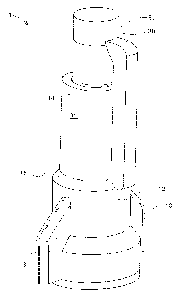
Figure 1 illustrates a first view of the electrical connector with cure-
in-place resin.
Figure 2 illustrates an exploded view of the electrical connector
with cure-in-place resin.
2
CA 03216910 2023- 10- 26

WO 2022/251780
PCT/US2022/072307
Figure 3 illustrates an exploded cross-sectional view of the electrical
connector with cure-in-place resin.
Figure 4 illustrates an assembled cross-sectional view of the
electrical connector with cure-in-place resin.
Figure 5 illustrates a second view, showing removal of the pull tab,
of the electrical connector with cure-in-place resin.
Figure 6 illustrates a third view, showing compression of the sliding
cartridge, of the electrical connector with cure-in-place resin.
Figure 7 illustrates a cross-sectional view, showing the resin around
the wires, of the electrical connector with cure-in-place resin.
Best Mode for Carrying Out the Invention
Reference will now be made in detail to the presently preferred
embodiments of the invention, examples of which are illustrated in
the accompanying drawings. Throughout the following detailed
description, the same reference numerals refer to the same
elements in all figures.
Referring to Figure 1, a first view of the electrical connector with
cure-in-place resin is shown.
The electrical connector with cure-in-place resin 1 is shown with
body 10, base 12, optional wings 13, and tip 14.
The sliding cartridge 30 is shown with head 31 fully extended
upward, ready for the electrical connector with cure-in-place resin 1
to be installed.
Referring to Figures 2 and 3, an exploded view of the electrical
connector with cure-in-place resin is shown.
The primary components of the electrical connector with cure-in-
place resin 1 include a sliding cartridge 30 with pull tab 32, body
10, resin cartridge 40, puncturing device 20, and shield 18.
3
CA 03216910 2023- 10- 26

WO 2022/251780
PCT/US2022/072307
The puncturing device 20 includes a piercing tip 22 and one or more
passageways 24 to allow resin to pass through.
The resin cartridge 40 is formed from a resin housing 42 that holds
resin 44.
Also shown are threads 16 that allow the electrical connector with
cure-in-place resin 1 to grip the conductors 54 (see Figure 4).
Referring to Figure 4, an assembled cross-sectional view of the
electrical connector with cure-in-place resin is shown.
The electrical connector with cure-in-place resin 1 is shown with
wire 50 installed, the wire 50 formed from insulation 52 and one or
more conductors 54.
The sliding cartridge 30 is shown with detent 38 that holds a
sealing ring 39. The sealing ring 39 prevents resin 44 from flowing
upward, between the body 10 and sliding cartridge 30.
The pull tab stop surface 34 rests against the body stop surface 15,
preventing the sliding cartridge 30 from sliding into the body 10
until the user is ready.
Referring to Figure 5, a second view, showing removal of the pull
tab, of the electrical connector with cure-in-place resin is shown.
The pull tab 32 is removed by an upward, rotating motion. This
motion separates the pull tab stop surface 34 from the body stop
surface 15, thus freeing the sliding cartridge 30 to move into the
body 10.
The pull tab 32 is optionally removable, able to separate at the pull
tab break point 36.
Referring to Figure 6, a third view, showing compression of the
sliding cartridge, of the electrical connector with cure-in-place resin
is shown.
4
CA 03216910 2023- 10- 26

WO 2022/251780
PCT/US2022/072307
The sliding cartridge 30 is pressed into the body 10, forcing resin 44
(see Figure 4) to surround the wire 50 (see Figure 7).
Referring to Figure 7, a cross-sectional view, showing the resin
around the wires, of the electrical connector with cure-in-place resin
is shown.
The sliding cartridge 30 has forced the resin 44 (see Figure 4) to
surround the wire 50, resulting in cured resin 46.
The wire 50 is now integral to the electrical connector with cure-in-
place resin 1. The cured resin 46 is protecting the wire 50 from
water and from loosening.
The shield 18 substantially confines the resin to the space around
the wire 50, minimizing leaks.
Equivalent elements can be substituted for the ones set forth above
such that they perform in substantially the same manner in
substantially the same way for achieving substantially the same
result.
It is believed that the system and method as described and many of
its attendant advantages will be understood by the foregoing
description. It is also believed that it will be apparent that various
changes may be made in the form, construction, and arrangement of
the components thereof without departing from the scope and spirit
of the invention or without sacrificing all of its material advantages.
The form herein before described being merely exemplary and
explanatory embodiment thereof. It is the intention of the following
claims to encompass and include such changes.
CA 03216910 2023- 10- 26

Representative Drawing
A single figure which represents the drawing illustrating the invention.
Administrative Status

2024-08-01:As part of the Next Generation Patents (NGP) transition, the Canadian Patents Database (CPD) now contains a more detailed Event History, which replicates the Event Log of our new back-office solution.

Please note that "Inactive:" events refers to events no longer in use in our new back-office solution.

For a clearer understanding of the status of the application/patent presented on this page, the site Disclaimer , as well as the definitions for Patent , Event History , Maintenance Fee  and Payment History  should be consulted.

Event History

Description Date
Letter Sent 2024-01-16
Inactive: Grant downloaded 2024-01-16
Grant by Issuance 2024-01-16
Inactive: Cover page published 2024-01-15
Pre-grant 2023-12-05
Inactive: Final fee received 2023-12-05
Notice of Allowance is Issued 2023-11-27
Letter Sent 2023-11-27
Inactive: Cover page published 2023-11-23
Inactive: Approved for allowance (AFA) 2023-11-17
Inactive: Report - QC failed - Minor 2023-11-17
Inactive: IPC assigned 2023-11-01
Inactive: First IPC assigned 2023-11-01
Advanced Examination Determined Compliant - PPH 2023-10-27
Advanced Examination Requested - PPH 2023-10-27
Amendment Received - Voluntary Amendment 2023-10-27
Letter Sent 2023-10-26
All Requirements for Examination Determined Compliant 2023-10-26
Inactive: IPC assigned 2023-10-26
Letter sent 2023-10-26
Priority Claim Requirements Determined Compliant 2023-10-26
Request for Priority Received 2023-10-26
Small Entity Declaration Determined Compliant 2023-10-26
National Entry Requirements Determined Compliant 2023-10-26
Application Received - PCT 2023-10-26
Request for Examination Requirements Determined Compliant 2023-10-26
Application Published (Open to Public Inspection) 2022-12-01

Abandonment History

There is no abandonment history.

Fee History

Fee Type Anniversary Year Due Date Paid Date
Request for examination - small 2023-10-26
Basic national fee - small 2023-10-26
Final fee - small 2023-12-05
MF (patent, 4th anniv.) - small 2026-05-13 2024-03-29
MF (patent, 2nd anniv.) - small 2024-05-13 2024-03-29
MF (patent, 3rd anniv.) - small 2025-05-13 2024-03-29
Owners on Record

Note: Records showing the ownership history in alphabetical order.

Current Owners on Record
TAYLOR HARDIN
Past Owners on Record
None
Past Owners that do not appear in the "Owners on Record" listing will appear in other documentation within the application.
Documents

To view selected files, please enter reCAPTCHA code :


To view images, click a link in the Document Description column (Temporarily unavailable). To download the documents, select one or more checkboxes in the first column and then click the "Download Selected in PDF format (Zip Archive)" or the "Download Selected as Single PDF" button.

List of published and non-published patent-specific documents on the CPD .

If you have any difficulty accessing content, you can call the Client Service Centre at 1-866-997-1936 or send them an e-mail at CIPO Client Service Centre.

({010=All Documents, 020=As Filed, 030=As Open to Public Inspection, 040=At Issuance, 050=Examination, 060=Incoming Correspondence, 070=Miscellaneous, 080=Outgoing Correspondence, 090=Payment})


Document
Description 
Date
(yyyy-mm-dd) 
Number of pages   Size of Image (KB) 
Drawings 2024-01-14 7 124
Claims 2024-01-14 4 97
Abstract 2024-01-14 1 15
Description 2024-01-14 5 165
Description 2023-10-25 5 165
Drawings 2023-10-25 7 124
Claims 2023-10-25 4 97
Abstract 2023-10-25 1 15
Representative drawing 2023-11-22 1 6
Representative drawing 2023-12-27 1 7
Electronic Grant Certificate 2024-01-15 1 2,526
Maintenance fee payment 2024-03-28 1 27
Commissioner's Notice - Application Found Allowable 2023-11-26 1 578
Courtesy - Acknowledgement of Request for Examination 2023-10-25 1 432
National entry request 2023-10-25 2 42
Declaration of entitlement 2023-10-25 1 29
Miscellaneous correspondence 2023-10-25 2 40
Patent cooperation treaty (PCT) 2023-10-25 1 54
International search report 2023-10-25 1 52
Patent cooperation treaty (PCT) 2023-10-25 1 62
National entry request 2023-10-25 8 182
Courtesy - Letter Acknowledging PCT National Phase Entry 2023-10-25 2 47
PPH supporting documents 2023-10-26 11 556
PPH request 2023-10-26 7 330
Final fee 2023-12-04 4 92