Note: Descriptions are shown in the official language in which they were submitted.
WO 2022/240881
PCT/US2022/028599
GLUELESS POCKETED SPRING CUSHIONING UNIT ASSEMBLER
CROSS-REFERENCE
100011 This application is a non-provisional of, and claims priority to, U.S.
Provisional Patent
Application No. 63/186,792, filed May 10, 2021, which is incorporated herein
by reference.
BACKGROUND
100021 The present application relates to methods, devices and systems for
construction of
cushioning units, and more particularly to automatic manufacture of pocketed
inner spring
cushioning units.
100031 Note that the points discussed below may reflect the hindsight gained
from the disclosed
inventive scope, and are not necessarily admitted to be prior art.
100041 Connecting rows of pocketed springs together using a scrim sheet
generally causes a
trampoline-like effect, i.e., compressing springs in one part of the unit
pulls on another part of the
unit.
100051 Glue connections between pocketed springs generally provide a
"crunchier" feeling to a
completed pocketed spring unit than connections made by thermal welding of
polymeric pocket
fabric.
100061 In some examples, glue, staples, rivets, or other connection methods
can be used to fasten
rows of pocketed springs together.
SUMMARY
100071 In described examples, a cushioning unit assembler includes first,
second, third, and
fourth rows of welding heads, a transport, and a feed module. The welding
heads have a welding
position and a retracted position. A main axis of the welding heads is
oriented in a first dimension
while in the welding position. The transport is disposed above the rows of
welding heads The
transport has a main axis oriented in a second dimension perpendicular to the
first dimension. The
feed module includes a pocketed spring intake and a pocketed spring outflow.
The transport is
mechanically coupled to enable the feed module to move in the second dimension
along a scope
of movement. An exit aperture of the outflow vertically aligns with welding
heads of the first row
that are in the welding position, and vertically aligns with welding heads of
the second row that
are in the welding position.
1
CA 03217143 2023- 10- 27
WO 2022/240881
PCT/US2022/028599
BRIEF DESCRIPTION OF THE DRAWINGS
[0008] The disclosed inventive scope will be described with reference to the
accompanying
drawings, which show important sample embodiments and which are incorporated
in the
specification hereof by reference, wherein:
[0009] FIG. 1A shows an example view of a cushioning unit assembler.
[0010] FIG. 1B shows an example view of rows of a continuously connected
string of pocketed
springs.
[0011] FIG. 1C shows an example view of a pocketed spring cushioning unit.
[0012] FIG. 2A shows an example view of a welding unit as used in the
cushioning unit
assembler of FIG. 1A.
[0013] FIG. 2B shows an example view of the welding unit shown in FIG. 2A.
[0014] FIG. 2C shows an example view of a welding module as used in the
welding unit of FIG.
2B.
[0015] FIG. 2D shows an example view of the welding module described with
respect to FIG.
2C.
100161 FIG. 2E shows an example view of the welding module described with
respect to FIG.
2C.
[0017] FIG. 2F shows an example view of the welding module described with
respect to FIG.
2C.
[0018] FIG. 2G shows an example view of the welding module described with
respect to FIG.
2C.
[0019] FIG. 3A shows an example view of a pocketed spring feed unit as used in
the cushioning
unit assembler of FIG. 1A.
[0020] FIG. 3B shows an example view of a pocketed spring feed unit as used in
the cushioning
unit assembler of FIG. 1 A.
[0021] FIG. 3C shows an example view of a pocketed spring feed unit as used in
the cushioning
unit assembler of FIG. 1A.
[0022] FIG. 3D shows an example view of a pocketed spring feed unit as used in
the cushioning
unit assembler of FIG. 1A, in the process of manufacturing a pocketed spring
cushioning assembly.
2
CA 03217143 2023- 10- 27
WO 2022/240881
PCT/US2022/028599
100231 FIG. 4 shows an example of an exit chute as used in the cushioning unit
assembler of
FIG. IA.
[0024] FIGS. 5A-5U show views of an example process for automatically
assembling a
pocketed spring cushioning unit.
[0025] FIG. 6A shows a view of a step in an example process for automatically
assembling a
pocketed spring unit.
[0026] FIG. 6B shows a view of a step in the example process of FIG. 6A for
automatically
assembling a pocketed spring unit.
[0027] FIG. 6C shows a view of a step in the example process of FIG. 6A for
automatically
assembling a pocketed spring unit.
[0028] FIG. 6D shows a view of a step in the example process of FIG. 6A for
automatically
assembling a pocketed spring unit.
DETAILED DESCRIPTION OF SAMPLE EMBODIMENTS
[0029] The numerous innovative teachings of the present application will be
described with
particular reference to presently preferred embodiments (by way of example,
and not of limitation).
The present application broadly describes inventive scope, and none of the
statements below
should be taken as limiting the claims generally.
[0030] In particular, the inventor has discovered how to construct an
automatic cushioning
assembler unit which can automatically manufacture pocketed spring cushioning
units without
glue and as a single continuously connected string of pocketed springs ¨
accordingly, without cuts
between rows of the cushioning units. A pocketed spring cushioning unit is
generally a rectangular
array of pocketed springs. After a cushioning unit is assembled, it can then
be padded with
upholstery and wrapped with a fabric cover to manufacture a cushioning
structure incorporating
pocketed springs, for example, a mattress, couch, or cushion.
[0031] Pocketed springs comprise springs in a pocket of a flexible, preferably
polymeric fabric
(typically plastic). As described below, cushioning units are manufactured
using a continuously
connected string of pocketed springs. In some examples, the continuously
connected string of
pocketed springs can be fed from a machine that assembles the continuously
connected string of
pocketed springs to an automatic cushioning unit assembler. The automatic
cushioning unit
assembler accepts the continuously connected string of pocketed springs, and
thermally welds
3
CA 03217143 2023- 10- 27
WO 2022/240881
PCT/US2022/028599
folded lengths of the continuously connected string of pocketed springs
together between
alternating pairs of pocketed springs.
[0032] A loading and welding process using a cushioning unit assembler 100 can
be summarized
as follows. Referring to FIGS. lA through 4, a continuously connected string
of pocketed springs
112 is fed into an intake port 312 in a receiver module 302 of a pocketed
spring feed unit 106. The
row of pocketed springs 112 is fed at a measured pace determined by a sprocket
314 in the receiver
module 302, down into a feed module 304 of the pocketed spring feed unit 106.
Guide rollers 324
of the feed module 304 feed a continuously connected string of pocketed
springs 112 onto either
a first row of anvils 204 or a second row of anvils 208 to form a row of
pocketed springs 120
supported by the respective row of anvils 204 or 208. The guide rollers 324 do
this by placing
fabric sections 118 between alternating, non-consecutive pairs of adjacent
pocketed springs 116
onto anvils 214 of the respective row of anvils 204 or 208. In some examples,
anvils 214 are
shaped like elongated wedges, or like fingers. The pocketed spring feed unit
106 folds the
continuously connected string of pocketed springs 112 back on itself after
feeding a row of
pocketed springs 120 onto a respective row of anvils 204 or 208. This enables
successive rows
120 of the continuously connected string of pocketed springs 112 to be
alternatingly fed onto the
first row of anvils 204 and the second row of anvils 208 without cutting the
continuously connected
string of pocketed springs 112 between rows 120 of a cushioning unit.
Accordingly, the pocketed
spring feed unit 106 feeds rows 120 of the continuously connected string of
pocketed springs 112
onto the first row of anvils 204, then the second row of anvils 208, then the
first row of anvils 204,
and so on.
[0033] A rate at which individual pocketed springs 116 of the continuously
connected string of
pocketed springs 112 are fed onto a row of anvils 204 or 208 is selected in
response to a rate at
which the pocketed spring feed unit 106 moves back and forth across the
cushioning unit assembler
100 feeding rows of pocketed springs 120 onto the rows of anvils 204 and 208.
Specifically, the
feed pace ¨ and correspondingly, a turning rate of the sprocket 314 ¨ is
selected so that, as
described above, adjacent individual anvils 214 in rows of anvils 204 and 208
support the rows of
pocketed springs 120 at alternating, non-consecutive fabric sections 118
between corresponding
pairs of adjacent pocketed springs 116. When a row of pocketed springs 120 has
been laid onto a
row of anvils 204 or 208, the top-most row of pocketed springs 120 is welded
to the row of
pocketed springs 120 immediately beneath. The row of anvils 204 or 208 that
did not most recently
4
CA 03217143 2023- 10- 27
WO 2022/240881
PCT/US2022/028599
receive a row of pocketed springs 120 participates in the welding.
Accordingly, a row of pocketed
springs 120 supported by the first row of anvils 204 is welded to a row of
pocketed springs 120
supported by the second row of anvils 204.
100341 To weld, a row of probes 202 or 206 that corresponds to and is paired
with the row of
anvils 204 or 208 (respectively) that will participate in the welding extends
from the body of the
cushioning unit assembler 100. The row of probes 202 or 206 then closes
together with the
corresponding row of anvils 204 or 208. Individual probes 212 of a row of
probes 202 or 206 are
paired with individual anvils 214 of a corresponding row of anvils 204 or 208.
A probe 212 closes
together with its paired anvil 214 by extending from a respective probe mount
222 to press layers
of pocketed spring fabric between the probe 212 and the anvil 214. (Together,
a probe mount 222
and a probe 212 make up a welding head 220.) A power source applies a welding
pulse of energy
to the row of probes 202 or 206, while it is closed together with its
corresponding row of anvils
204 or 208, to melt and thereby weld together the pressed layers of pocketed
spring fabric. After
the welds cool sufficiently to resist pulling apart, the row of probes 202 or
206 opens away from
the row of anvils 204 or 208, and the row of probes 202 or 206 retracts back
into the body of the
cushioning unit assembler 100.
100351 After welding, the feed module 304 rises, the row of anvils 204 or 208
that just
participated in welding retracts into the body of the cushioning unit
assembler 100, and that row
of anvils 204 or 208 rises and then extends into position to receive a new row
of pocketed springs
120. After both rows of anvils 204 and 208 have risen once (corresponding to
four paired rows of
pocketed springs 120 having been welded), one or both of the rows of anvils
204 and/or 208 lower
back to a starting height while still supporting the cushioning unit 110 that
is being assembled, and
the cycle repeats. Once a number of pocketed springs 116 corresponding to a
completed pocketed
spring cushioning unit 110 passes a cutter 326 in the feed module 304, the
cutter 326 cuts the
continuously connected string of pocketed springs 112, the guide rollers 324
guide fabric sections
118 between remaining pocketed springs 116 (pocketed springs 116 below the
cutter 326, but not
yet placed on a row of anvils 204 or 208) onto respective individual anvils
214, a final weld is
performed, and the rows of anvils 204 and 208 retract into the body of the
cushioning unit
assembler 100 to release the pocketed spring cushioning unit 110 from the
cushioning unit
assembler 100 through an exit chute 108.
CA 03217143 2023- 10- 27
WO 2022/240881
PCT/US2022/028599
100361 Weld strength and reliability are improved if the welding phalanges
(individual probes
212 and individual anvils 214, also referred to in the claims as welding
heads) are not separated
and extracted from a new weld until the weld has cooled and set. For example,
in some examples,
this can mean a waiting period before individual probes 212 are opened from
individual anvils
214.
[0037] Specific directions such as front, rear, left, and right are merely
exemplary, are used
solely to facilitate understanding of exemplary embodiments, and are in no way
intended to limit
disclosed inventive scope.
[0038] The disclosed innovations, in various embodiments, provide one or more
of at least the
following advantages. However, not all of these advantages result from every
one of the
innovations disclosed, and this list of advantages does not limit the
variously claimed inventive
scope.
= Fast pocketed spring unit assembly using NO GLUE;
= pocketed spring units, and cushioning assemblies incorporating pocketed
spring units,
are more comfortable and luxurious-feeling;
= lowered labor cost for no-glue pocketed spring unit assembly;
= reduced total cost for no-glue pocketed spring unit assembly;
= enables high throughput of no-glue pocketed spring unit assembly;
= cost-effective welding of entire rows of pocketed springs;
= stronger connections between rows of pocketed springs;
= reduced likelihood of unmoored pockets;
= reduced likelihood of loose springs;
= reduced environmental impact of pocketed spring unit construction;
= reduced environmental impact of cushioning assembly construction and
maintenance;
= rows of pocketed springs can be fully welded together in a single weld
event, with
controllable vertical weld location, extent, width, and strength;
= reduced weight of pocketed spring unit;
= reduced weight of cushioning assembly;
= lower cushioning assembly transportation cost per unit; and
= increased cushioning unit durability.
6
CA 03217143 2023- 10- 27
WO 2022/240881
PCT/US2022/028599
100391
Some exemplary parameters will be given to illustrate the relations
between these and
other parameters. However, it will be understood by a person of ordinary skill
in the art that these
values are merely illustrative, and will be modified by scaling of further
device generations, and
will be further modified to adapt to different materials or architectures if
used.
[0040]
The inventor has discovered new approaches to methods and systems for
manufacturing glueless pocketed spring cushioning units 110 for use in
mattresses and other
cushioning assemblies. Rapid, efficient, easily maintainable, and fully
automated methods and
systems for cushioning unit assembly are enabled and supported by accurate and
automated
loading of a single, continuously connected string of pocketed springs 112
onto rows of anvils 204
and 208 as rows of pocketed springs 120.
[0041]
Herein, a "cushioning assembly" is any cushioning structure
incorporating pocketed
springs, such as a mattress, couch, or cushion. A "cushioning unit" or
"pocketed spring unit" is
an assembly of pocketed springs used to manufacture a cushioning assembly,
such as by padding
the cushioning unit with upholstery and wrapping it with a fabric cover.
100421
In preferred embodiments, pockets are formed gluelessly by welding
together layers of
a flexible material, generally plastic, such as spun bonded polypropylene
(typically a lightweight
material, e.g., 1.5 ounces per square yard), using Joule heating effected by
current passed through
a heating element compressed against the fabric. By forming pockets of a
chosen size on a chosen
length and width of fabric, a continuously connected string of pockets of a
chosen length and sized
for a chosen diameter and length of spring can be produced.
[0043]
In preferred embodiments, uniform diameter springs are used. Uniform
diameter
springs can be manufactured by custom winding high tensile strength wire with
highly uniform
shape and thickness.
[0044]
Some examples use microcoil springs, which are small springs suitable
for use in
pocketed spring units incorporated into, for example, upholstery.
[0045]
Springs are inserted into pockets to form pocketed springs 116. Springs
can be inserted
into pockets oriented horizontally through a seam on top of the pocket, and
then beaten until they
reorient vertically. Generally, this results in a pocketed spring 116 that, in
a completed cushioning
assembly, can only be oriented in a single direction. For example, a bed made
in this way is
typically called "one sided-.
7
CA 03217143 2023- 10- 27
WO 2022/240881
PCT/US2022/028599
[0046] Preferably, springs are inserted oriented vertically through
a central seam on the side
of the pocket and allowed to expand to fill the pocket. A central seam can be
formed as disclosed
in U.S. Patent No. 6,131,892, and insertion through such a seam can be
performed as disclosed in
U.S. Pat. No. 6,260,331, both of which are incorporated herein by reference.
[0047] Pockets can be fashioned to be shorter than an uncompressed
spring, so that pocketed
springs 116 are constantly under load. Such constantly loaded springs are
referred to as preloaded.
Preloading a spring generally increases a pocketed spring's 116 useful
lifetime, by allowing its
spring constant to remain higher, for longer. Pocketed springs 116 with
preloaded springs are
generally manufactured by inserting the springs vertically compressed, and
allowing them to
expand vertically to fill respective pockets.
[0048] A continuously connected string of pocketed springs 110, in
which pocketed springs
116 are continuously connected to adjacent pocketed springs, such as by the
same fabric that forms
the pockets, can be formed as shown and described in, for example, U.S. Patent
No. 6,131,892.
[0049] The inventor has discovered that multiple adjacent lengths of
a folded, continuously
connected string of pocketed springs 112 can be efficiently connected together
to form pocketed
spring cushioning units 110. These pocketed spring cushioning units 110 look
like rectangular
arrays of pocketed springs 116 from above (see FIG. 1C).
[0050] Springs in completed pocketed spring units are typically
compressed very flat and
rolled up into tight cylinders for shipping.
[0051] Glue can be used in layers of a cushioning assembly
manufactured as disclosed herein,
but preferably is not used in the pocketed spring cushioning unit layer(s)
assembled using thermal
welds.
100521 Use of welding probes and anvils to press pocket fabric
between them and heat the
pocket fabric to form a polymer weld is disclosed by U.S. Pat. No. 9,221,670,
which is
incorporated herein by reference. U.S. Pat. No. 9,221,670 also discloses use
of vibrational,
inductive, or ohmic (Joule) heating to form polymer welds, as well as variable
vertical weld
location, extent, width, and strength. Use of wires (configured for Joule
heating) recessed into
channels in probes, into which anvils press pocket fabric to be heated and
welded together, is
disclosed by U.S. Pat. No. 9,427,092, which is incorporated herein by
reference.
[0053] As used herein, "automatic- preferably refers to process
performance without requiring
human intervention except for ordinary installation, initial startup activity
and ordinary
8
CA 03217143 2023- 10- 27
WO 2022/240881
PCT/US2022/028599
maintenance. In some examples, initial startup activity occurs which involves
manual intervention
by an operator or mechanic, e.g., daily, per-shift and/or per-on/off assembler
power cycle, or for
assembler debugging or other maintenance. Manual intervention can also be used
to adjust process
parameters, such as pressure exerted by a probe/anvil pair during a weld,
welding power and
duration, pocketed spring feed rate, and the number of pocketed springs on
each side of a
completed cushioning unit.
[0054] As used herein, the "front" of a cushioning unit assembler
100 refers to the side of a
cushioning unit assembler 100 on which a cushioning unit is assembled, and the
-body" of a
cushioning unit assembler 100 refers to the portion of the cushioning unit
assembler 100 in which
the individual probes 212 and individual anvils 214 are housed when they are
not in an extended
position.
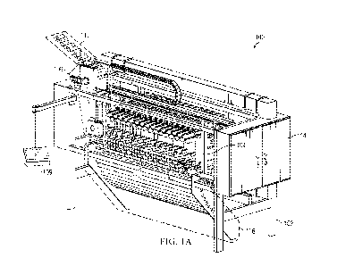
[0055] FIG. lA shows an example view of a cushioning unit assembler
100. The cushioning
unit assembler 100 includes a frame 102, a welding unit 104, a pocketed spring
feed unit 106, an
exit chute 108, and a welding controller and interface 109. The welding unit
104 includes multiple
welding modules 218. Individual welding modules 218 include a first row of
probes 202, a first
row of anvils 204, a second row of probes 206, and a second row of anvils 208.
Welding modules
218 are shown in and further described with respect to FIGS. 2A through 2G.
The pocketed spring
feed unit 106 includes a receiver module 302 that receives the continuously
connected string of
pocketed springs 112, and a feed module 304 that feeds the continuously
connected string of
pocketed springs 112 onto first and second rows of anvils 204 and 208. The
pocketed spring feed
unit 106 also includes traverse rails 308 that the pocketed spring feed unit
106 uses to move back
and forth above the rows of anvils 204 and 208 while feeding the continuously
connected string
of pocketed springs 112 onto the rows of anvils 204 and 208. The pocketed
spring feed unit 106
is shown in and further described with respect to FIGS. 3A through 3D.
[0056] The frame 102 supports the rest of the cushioning unit
assembler 100. A pocketed
spring cushioning unit 110 in the process of assembly is shown placed on the
welding unit 104. A
row of pocketed springs 120 is shown entering the top of the pocketed spring
feed unit 106, and
exiting the bottom of the pocketed spring feed unit 106 prior to being placed
on the welding unit
104 and welded to the pocketed spring cushioning unit 110. A power cabinet 114
distributes power
to the cushioning unit assembler 100, including to welding heads 220 for
welding pulses by
respective individual probes 212 (see, for example, FIG. 2C).
9
CA 03217143 2023- 10- 27
WO 2022/240881
PCT/US2022/028599
100571 The welding controller and interface 109 can control the
welding process including, for
example, welding temperature and pressure, spring feed rate, pocketed spring
feed unit 106
movement rate, pocketed spring cushioning unit 110 width in pocketed springs
116 (corresponding
to a number of probe/anvil pairs used to assemble the pocketed spring
cushioning unit 110), a
number of rows of pocketed springs 120 in a pocketed spring cushioning unit
110, and a cooling
time or target temperature (or other sensed characteristic) before rows of
probes 202, 206 and
corresponding rows of anvils 204, 208 open apart after welding rows of
pocketed springs 116
together. The welding controller and interface 109 can also control process
ordering and
execution, for example, as described with respect to views 500a through 500u
and steps 502
through 542 of FIGS. 5A through 5U; views 600a through 600d and steps 602
through 608 of
FIGS. 6A through 6D; and in various examples described herein. In some
examples, the welding
controller and interface 109 can require operators to present valid access
credentials.
100581 FIG. 1B shows an example view of rows of a continuously
connected string of
pocketed springs 112. Adjacent pocketed springs 116 are connected by portions
of interstitial
pocket spring fabric referred to herein as fabric sections 118. Arrows
indicate where the rows of
the continuously connected string rows of pocketed springs 112 may connect to
additional rows
of the continuously connected string of pocketed springs 110.
100591 FIG. IC shows an example view of a pocketed spring cushioning
unit 110. The
pocketed spring cushioning unit 110 includes a selected number of rows of
pocketed springs 120.
Rows of pocketed springs 120 are formed by folding the continuously connected
string of pocketed
springs 112 over, preferably without cutting the continuously connected string
of pocketed springs
112. Accordingly, the pocketed spring cushioning unit 110 comprises a single,
continuously
connected string of pocketed springs 112, repeatedly folded over against and
welded to itself to
form a selected number of rows of pocketed springs 120. Each row of pocketed
springs 120 is a
selected number of pocketed springs 116 wide. Adjacent row of pocketed springs
120 are
connected to each other both by fabric sections 118 on alternating sides of
the pocketed spring
cushioning unit 110, and by welds formed by pressing layers of pocketed fabric
together at fabric
sections 118 and heating the fabric until it melts together to form a weld
(for example, a plastic
weld).
100601 Welds are located between non-consecutive (preferably
alternating) pairs of adjacent
pocketed springs 116. For example, number fabric sections 118 from one to an
integer N from
CA 03217143 2023- 10- 27
WO 2022/240881
PCT/US2022/028599
right to left in rows of pocketed springs 120, and number rows of pocketed
springs 120 from one
to an integer M from bottom to top within the pocketed spring cushioning unit.
Using this
numbering, welds can be between, for example, odd numbered fabric sections 118
to connect first
and second rows of pocketed springs 120, even numbered fabric sections 118 to
connect second
and third rows of pocketed springs 120, odd numbered fabric sections 118 to
connect third and
fourth rows of pocketed springs 120, and so on.
[0061] FIG. 2A shows an example view of a welding unit 104 as used
in the cushioning unit
assembler 100 of FIG. 1A. The welding unit 104 includes multiple welding
modules 218.
Together, the multiple welding modules 218 contribute to the welding unit 104
a first row of probes
202, a first row of anvils 204, a second row of probes 206, and a second row
of anvils 208. Each
row of probes 202, 206, and each row of anvils 204, 208, is arranged in a line
in a first dimension
209, so that the first row of probes 202, the first row of anvils 204, the
second row of probes 206,
and the second row of anvils 208 are mutually parallel. The first dimension is
also referred to as
a width dimension of the rows of probes 202 and 206 and anvils 204 and 208.
The main (long)
axes of individual probes 212 and the main axes of individual anvils 214 are
oriented in a second
dimension 215, so that the main axes of individual probes 212 and individual
anvils 214 are
mutually parallel. (Herein, dimension refers to both possible directions, or
orientations, along or
parallel to a line.) Usefully, the first dimension 209 and the second
dimension 215 are also parallel
to the floor. The floor is beneath and supports the cushioning unit assembler
100, and is not shown.
[0062] Individual probes 212 are paired with individual anvils 214,
so that an individual probe
212 / individual anvil 214 pair can close together to weld. An individual
anvil 214 of a leftmost
welding module 219 is used during a welding process after a first row of
pocketed springs 120 of
a pocketed spring cushioning unit 110 has been laid down onto a first row of
anvils 204. The
individual anvil 214 of the leftmost welding module 219, which can be referred
to as a turning
anvil 221, assists in folding over the row of pocketed springs 112 without
pulling the first row of
pocketed springs 120 off of the first row of anvils 204. This enables a second
row of pocketed
springs 120 to be laid over the first row of pocketed springs 120 by arranging
the second row of
pocketed springs 120 atop a second row of anvils 208. In some examples,
because the turning
anvil 221 is only used once, it does not move up and down.
[0063] FIG. 2B shows an example view of the welding unit 104 shown
in FIG. 2A. The
welding unit 104 comprises multiple welding modules 218.
11
CA 03217143 2023- 10- 27
WO 2022/240881
PCT/US2022/028599
100641 FIG. 2C shows an example view of a welding module 218 as used
in the welding unit
104 of FIG. 2B. A welding module 218 includes a welding head 220 and an
individual anvil 214,
and is mounted on the body 102 of the cushioning unit assembler 100 by a
mounting foot 223. In
some examples, the mounting foot 223 can include a vertical actuator 225 to
raise and lower a
corresponding welding module 218. The vertical actuator can have, for example,
a five inch
stroke.
[0065] The welding head 220 includes a probe mount 222, the
individual probe 212 that
corresponds to and is paired (and vertically aligned) with the individual
anvil 214, and multiple
probe hydraulic servos 224a, 224b, 224c. The probe hydraulic servos 224a,
224b, 224c connect
the probe mount 222 to the individual probe 212 and enable the individual
probe 212 to move up
and down. The probe mount 222 of the welding head 220 is mounted on a first
hydraulic servo
226. The individual anvil 214 is mounted on a second hydraulic servo 228. The
first and second
hydraulic servos 226, 228 move the welding head 220 and the individual anvil
214, respectively,
forwards and backwards in the second dimension 215. This moves the individual
probe 212 and
individual anvil 214 into and out of the body of the cushioning unit assembler
100. The individual
anvil 214 is available to help support a row of pocketed springs for a
cushioning unit assembly
process when the individual anvil 214 is extended out of the body of the
cushioning unit assembler
100.
[0066] The first and second hydraulic servos 226, 228 are mounted on
a first vertically-
oriented rail 230 and a second vertically-oriented rail 232. The vertically-
oriented rails 230, 232
enable the individual probe 212 and the individual anvil 214 to move up and
down together (for
example, synchronously).
[0067] The welding module also includes a first power connector 210a
and a second power
connector 210b. The first power connector 210a connects respective welding
heads 220 to the
second power connector 210b (for example, using power cables, which are not
shown). The
second power connector 210b connects to the power cabinet 114 to provide power
to welding
heads 220 ¨ and accordingly, to individual probes 212 ¨ for welding pulses.
[0068] Example individual probes 212 and individual anvils 214 are
described in U.S. Pat. No.
9,427,092, which is incorporated herein by reference.
[0069] FIG. 2D shows an example view of the welding module 218
described with respect to
FIG. 2C. In FIG. 2C, the individual probe 212 and the individual anvil 214 are
separated from
12
CA 03217143 2023- 10- 27
WO 2022/240881
PCT/US2022/028599
each other, or "open." In FIG. 2D, the individual probe 212 and the individual
anvil 214 are
pressed together, or "closed together," so that a welding surface of the
individual probe 212 makes
flush contact with a facing surface of the individual anvil 214. When layers
of pocketed spring
fabric, and accordingly the respective fabric sections 118 of those layers,
are pressed between an
individual probe 212 and an individual anvil 214 that are closed together,
power (a welding pulse)
can be applied to the individual probe 212 to cause the individual probe 212
to thermally weld
together the layers of pocketed spring fabric.
100701 Different individual probes 212 and different individual
anvils 214 are separately
mechanically coupled to respective first hydraulic servos 226 and to first and
second rails 230, 232
(individual probes 212 are so coupled via respective welding units 220).
Accordingly, different
pairs of individual probes 212 and individual anvils 214 can move
independently from each other.
This enables different individual probes 212 and individual anvils 214 to
independently move into
and out of the body of the welding unit 104, and to be independently raised
and lowered. Motion
into and out of the body of the welding unit 104 can also be viewed as
extension of individual
probes 212 from, and retraction of the individual probes 212 back into, the
body of the cushioning
unit assembler 100. Individual probes 212 and individual anvils 214 are
available to weld rows of
pocketed springs 120 together when the individual probes 212 and individual
anvils 214 are
extended from the body of the cushioning unit assembler 100.
100711 Independent movement of pairs of individual probes 212 and
individual anvils 214
enables alternating pairs of individual probes 212 and individual anvils 214
to be used to weld
rows of pocketed springs. For example, paired individual probes 212 and
individual anvils 214
from a first, third, fifth, seventh, etc. welding module 218 in a welding unit
can be used to weld a
lower row of pocketed springs 120 to an upper row of pocketed springs 120 laid
on top of the
lower row of pocketed springs 120. This welding can be done by welding
together fabric sections
118 between alternating pairs of pocketed springs 116 in each of the two rows
of pocketed springs
120. For example, fabric sections 118 between the first and second pocketed
springs 116, third
and fourth pocketed springs 116, fifth and sixth pocketed springs 116, etc.,
in upper and lower
rows of pocketed springs 120 can be welded together. Fabric sections 118
between the second and
third pocketed springs 116, fourth and fifth pocketed springs 116, etc., in
upper and lower rows of
pocketed springs 120 are skipped to leave available locations where the upper
row of pocketed
springs 120 can be welded to a next row of pocketed springs 120.
13
CA 03217143 2023- 10- 27
WO 2022/240881
PCT/US2022/028599
100721 A number of individual probes 212 within a row of probes 202
or 206 and the number
of individual anvils 214 within a row of anvils 204 or 208 that moves during a
welding cycle is
selectable. Accordingly, the cushioning unit assembler 100 can move an
appropriate, efficient
number of individual probes 212 and individual anvils 214 within respective
rows of probes and
anvils 202, 204, 206, 208 to make pocketed spring cushioning units 110 that
are a selected number
of pocketed springs 116 wide.
[0073] Returning to FIG. 2A, adjacent individual probes 212 within a
row of probes 202, 206,
and adjacent individual anvils 214 within a row of anvils 204, 208, are
slightly more than two
times a diameter of a pocketed spring 116 apart. Specifically, such adjacent
individual probes 212
and adjacent individual anvils 214 are spaced apart by, respectively, twice
the diameter of a
pocketed spring 116 plus the length of a fabric section 118 between an
adjacent pair of pocketed
springs 116. This corresponds to the distance between the middle of a fabric
section 118 between
a pair of adjacent pocketed springs 116, and the middle of a fabric section
between a nearest non-
consecutive pair of adjacent pocketed springs 116: for example, from the
middle of a fabric section
118 between first and second pocketed springs 116 in a row of pocketed springs
120, to the middle
of a fabric section 118 between third and fourth pocketed springs in the row
of pocketed springs
120. In some examples, these lengths can correspond to pocketed springs 116
with a diameter of
2.5 inches and fabric sections 118 that are .375 inches long, so that adjacent
individual probes 212
and adjacent individual anvils 214 are (respectively) 5.375 inches apart in
the first dimension 209.
The length of fabric sections 118 is selected to be at least long enough for
individual probes 212
and individual anvils 214 to be inserted between adjacent pairs of pocketed
springs 116.
[0074] Also, individual probes 212 in the first row of probes 202
are offset in the first
dimension 209 by 2.6875 inches, from nearest individual probes 212 in the
second row of probes
206. This corresponds to half the distance between adjacent individual probes
212 within the first
row of probes 202 (or within the second row of probes 206). Similarly,
individual anvils 214 in
the first row of anvils 204 are offset in the first dimension 209 by 2.6875
inches from nearest
individual anvils 214 in the second row of anvils 208.
[0075] The separation between adjacent individual anvils 214 within
a row of anvils 204 or
208 enables the pocketed spring feed unit 106 to feed a row of pocketed
springs 112 onto a row of
anvils 204 or 208, while individual anvils 214 in the respective row of anvils
204 or 208 hold
already-fed portions of the row of pocketed springs 112 in place (for example,
in position for
14
CA 03217143 2023- 10- 27
WO 2022/240881
PCT/US2022/028599
welding). Accordingly, because the pocketed spring cushioning unit 110 is an
integral structure
held together by thermal welds, this also holds the pocketed spring cushioning
unit 110 in place.
The offset distance between individual anvils 214 in different rows of anvils
204, 208 enables the
rows of anvils 204, 208 to receive successive rows of pocketed springs 120
comprising folded-
over portions of a continuously connected string of pocketed springs 112.
[0076] FIG. 2E shows an example view of the welding module 218
described with respect to
FIG. 2C. In FIG. 2E, the individual anvil 214 is out (extended), and the
individual probe 212 (and
corresponding welding head 220) is retracted into the body of the cushioning
unit assembler 100.
[0077] FIG. 2F shows an example view of the welding module 218
described with respect to
FIG. 2C. In FIG. 2E, the individual anvil 214 and the individual probe 212
(and corresponding
welding head 220) are retracted into the body of the cushioning unit assembler
100.
[0078] FIG. 2G shows an example view of the welding module 218
described with respect to
FIG. 2C. In FIG. 2G, the individual anvil 214 and the individual probe 212
(and corresponding
welding head 220) are out (extended) and are opened away from each other.
100791 FIG. 3A shows an example view of a pocketed spring feed unit
106 as used in the
cushioning unit assembler 100 of FIG. 1A. This view is oriented in the second
dimension 215.
The pocketed spring feed unit 106 includes a receiver module 302, a feed
module 304, hydraulic
servos 306a, 306b, 306c connecting the receiver module 302 to the feed module
304, and traverse
rails 308. Traverse rails 308 can be, for example, hardened precision "V"
rails.
[0080] The receiver module 302 is mounted on the traverse rails 308
of the pocketed spring
feed unit 106 (a second traverse rail 308 is visible in FIG. 3B) by rollers
310. Rollers 310 can be,
for example, precision "V" rollers. The receiver module 302 is motorized to
move back and forth
in the first dimension 209, so that the feed module 304 moves back and forth
in the first dimension
209 to deposit the continuously connected string of pocketed springs 112 onto
the first and second
rows of anvils 204 and 208 (at different times in a pocketed spring unit 110
assembly process).
Accordingly, the traverse rails 308 are disposed in the first dimension 209.
[0081] The receiver module 302 includes the rollers 310, an intake
port 312, and a sprocket
314 located near the intake port 312. The intake port 312 is disposed to
receive a continuously
connected string of pocketed springs 112 comprising individual pocketed
springs 1116. The
sprocket 314 is sized and toothed to accept individual pocketed springs 116
into the gaps 320
between adjacent teeth 322 of the sprocket 314. The sprocket 314 is motorized
to move the
CA 03217143 2023- 10- 27
WO 2022/240881
PCT/US2022/028599
continuously connected string of pocketed springs 112 at a rate corresponding
to a feed rate of the
continuously connected string of pocketed springs 112 onto a row of anvils 204
or 208. This
facilitates proper placement of the continuously connected string of pocketed
springs 112 onto the
row of anvils 204 or 208 in preparation for welding. The receiver module 302
passes the
continuously connected string of pocketed springs 112 to the feed module 304.
The feed module
304 feeds the continuously connected string of pocketed springs onto the row
of anvils 204 or 208.
[0082] The feed module 304 includes guide rollers 324, a cutter 326,
and an exit port 328 (also
referred to herein as an outflow). The feed module 304 accepts the
continuously connected string
of pocketed springs 112, and feeds the continuously connected string of
pocketed springs 112 onto
the row of anvils 204 or 208. The guide rollers 324 guide the continuously
connected string of
pocketed springs 112 as it passes the exit port 328 so that adjacent
individual anvils 214 in the row
of anvils 204 or 208 support adjacently successive fabric sections between
adjacently successive
(non-consecutive, alternating) pairs of adjacent individual pocketed springs
116. In some
examples, the guide rollers 324 push alternating (non-consecutive) fabric
sections 118 of the
continuously connected string of pocketed springs 112 onto consecutive
individual anvils 214 in a
row of anvils 204 or 208, so that the fabric sections 118 are seated on
(preferably, with a full length
of the fabric in the second dimension 215 making contact with) respective
individual anvils 214,
and the respective individual anvils 214 are straddled by respective adjacent
pairs of pocketed
springs 116. The cutter 326 cuts the continuously connected string of pocketed
springs 112 after
a number of pocketed springs has passed the cutter 326 equal to the number of
pocketed springs
in a completed pocketed spring cushioning unit. Accordingly, the cutter 326
separates a portion
of the continuously connected string of pocketed springs 112 corresponding to
completion of a
pocketed spring cushioning unit 110 currently being processed, from the rest
of the continuously
connected string of pocketed springs 112. For example, there may be a single
row of welds left to
complete the pocketed spring cushioning unit currently being processed from a
next pocketed
spring cushioning unit. The guide rollers 324 hold up the cut, not yet placed
portion of the
continuously connected string of pocketed springs so that the cut end can be
placed properly by
the guide rollers 324 as the feed module 304 moves across the final anvils 214
of the respective
row of anvils 204 or 208 that are intended to receive pocketed springs.
[0083] The pocketed spring feed unit 106 is situated above the rows
of probes and anvils 202,
204, 206, 208 so that the pocketed spring feed unit 106 can feed the
continuously connected string
16
CA 03217143 2023- 10- 27
WO 2022/240881
PCT/US2022/028599
of pocketed springs 112 vertically onto the rows of anvils 204, 208, so that
individual anvils 214
within a row of anvils 204 or 208 accept the continuously connected string of
pocketed springs
112 serially in the first dimension 209.
[0084] FIG. 3B shows an example view of a pocketed spring feed unit
106 as used in the
cushioning unit assembler 100 of FIG. 1A.
[0085] FIG. 3C shows an example view of a pocketed spring feed unit
106 as used in the
cushioning unit assembler 100 of FIG. 1A. This view is oriented in the first
dimension 209.
[0086] FIG. 3D shows an example view 330 of a pocketed spring feed
unit 106 as used in the
cushioning unit assembler 100 of FIG. 1A, in the process of manufacturing a
pocketed spring
cushioning assembly 110.
[0087] FIG. 4 shows an example of an exit chute 108 as used in the
cushioning unit assembler
100 of FIG. 1A. An exit chute 108 includes a curved support structure 402, on
which multiple exit
rollers 404 are mounted. The exit rollers 404 are situated to catch the
pocketed spring cushioning
unit 110 as it is assembled, and direct the pocketed spring cushioning unit
110 to where it can be
moved ¨ manually or automatically ¨ away from the cushioning unit assembler
100. The exit
chute 108 can be arranged to use gravity to feed the assembled pocketed spring
cushioning unit
110 out of the cushioning unit assembler 100. In some examples, one or more of
the exit rollers
404 is motorized to assist gravity in moving the pocketed spring cushioning
unit 110. The exit
chute 108 can also include a support (not shown) arranged to bear some of the
weight of a
cushioning unit 110 during construction, so that the rows of anvils 204 and
208, and the welds
holding the rows of pocketed springs 120 of the cushioning unit 110 together,
bear a reduced load.
The support can include, for example, a bar, plate, rod, mesh, or other load-
bearing material, and
can move downward through the exit chute 108 with the cushioning unit 110 as
it is assembled
using, for example, a spring or motor.
[0088] FIGS. 5A through 5Q show an example process for automatically
assembling a
pocketed spring unit 110.
[0089] FIG. 5A shows a view 500a of a step 502 in an example process
for automatically
assembling a pocketed spring unit 110. FIG. 5B shows a view 500b of a step 504
in an example
process for automatically assembling a pocketed spring unit 110. In FIGS. 5A
and 5B, the first
row of anvils 204 is extended. Also, the pocketed spring feed unit 106 is
loaded with a
17
CA 03217143 2023- 10- 27
WO 2022/240881
PCT/US2022/028599
continuously connected string of pocketed springs 112, and is located at a
first end of the first row
of anvils 204 (on the right in the figure).
100901 FIG. SC shows a view 500c of a step 506 in an example process
for automatically
assembling a pocketed spring unit 110. The pocketed spring feed unit 106 feeds
a first row of
pocketed springs 120 onto the first row of anvils 204 while moving from the
first end past a second
end of the first row of anvils 204 (from right to left in the figure). The
pocketed spring feed unit
106 feeds the row of pocketed springs 112 so that adjacent individual anvils
214 within the first
row of anvils 204 support fabric sections 118 between non-consecutive adjacent
pairs of pocketed
springs 116. The exit port 328 of the feed module 304 of the pocketed spring
feed unit 106 is
located sufficiently close to the first row of anvils 204 so that the guide
rollers 324 push the row
of pocketed springs 120 down onto the first row of anvils 204. Accordingly,
individual anvils 214
are located between pairs of adjacent pocketed springs 116 and support
respective fabric sections
118 between the pairs of adjacent pocketed springs 116.
100911 FIG. 513 shows a view 500d of a step 508 in an example
process for automatically
assembling a pocketed spring unit 110. The turning anvil 221 extends to
facilitate laying a second
row of pocketed springs 120 atop the first row of pocketed springs 120 without
dislodging the first
row of pocketed springs 120 from its position resting on the first row of
anvils 204.
100921 FIG. SE shows a view 500e of a step 510 in an example process
for automatically
assembling a pocketed spring unit 110. The second row of anvils 208 extends.
Also, the feed
module 304 rises ¨ telescopes upward, closer to the receiving module 302 ¨ so
that in a next step
512 the guide rollers 324 will be at the correct height within the cushioning
unit assembler 100 to
closely engage with, and push the row of pocketed springs 112 onto, the second
row of anvils 208.
100931 FIG. SF shows a view 500f of a step 512 in an example process
for automatically
assembling a pocketed spring unit 110. The pocketed spring feed unit 106
begins to lay a second
row of pocketed springs 120 atop (and similarly to) the first row of pocketed
springs 120 while the
turning anvil 221 holds the first row of pocketed springs 120 in place.
100941 FIG. 5G shows a view 500g of a step 514 in an example process
for automatically
assembling a pocketed spring unit 110. The pocketed spring feed unit 106 feeds
the second row
of pocketed springs 120 onto the second row of anvils 208 while moving from
the second end past
a first end of the second row of anvils 208 (from left to right in the
figure). The pocketed spring
feed unit 106 feeds the row of pocketed springs 112 so that adjacent
individual anvils 214 within
18
CA 03217143 2023- 10- 27
WO 2022/240881
PCT/US2022/028599
the second row of anvils 208 support fabric sections 118 between non-
consecutive adjacent pairs
of pocketed springs 116, in a similar manner and resulting in similar
engagement between
individual anvils 214 and fabric sections 118 between alternating pairs of
adjacent pocketed
springs 116 as with feeding to form the first row of pocketed springs 120.
100951 FIG. 5H shows a view 500h of a step 516 in an example process
for automatically
assembling a pocketed spring unit 110. The welding heads 220 of the first row
of probes 202 ¨
which are paired with the first row of anvils 204 ¨ extend from the bodies of
respective welding
modules 118. The welding heads 220 extend so that they are in an open
(separated) position with
respect to the first row of anvils 204.
100961 FIG. 51 shows a view 500i of a step 518 in an example process
for automatically
assembling a pocketed spring unit 110. The individual probes 212 in the first
row of probes 202
close together with the individual anvils 214 in the first row of anvils 204.
A welding pulse is
applied to the individual probes 212 in the first row of probes 202 to weld
the first and second
rows of pocketed springs 120 together. The welds are formed at fabric sections
118 that pairs of
individual probes 212 and individual anvils 214 in the first rows of probes
202 and anvils 204
press together. The welding action can be performed using, for example, a
resistive wire that heats
sufficiently to cause the plastic fabric in which the springs are pocketed to
melt so that
100971 FIG. 5J shows a view 500j of a step 520 in an example process
for automatically
assembling a pocketed spring unit 110. After the welds and/or the surface(s)
of the individual
probes 212 and/or individual anvils 214 engaged in performing the weld have
cooled sufficiently
to be secure (resistant to pulling apart), the individual probes 212 in the
first row of probes 202
open (separate) from the individual anvils 214 in the first row of anvils 204.
100981 FIG. 5K shows a view 500k of a step 522 in an example process
for automatically
assembling a pocketed spring unit 110. The first row of probes 212, the first
row of anvils 214,
and the turning anvil 221 withdraw back into the body of the cushioning unit
assembler 100. The
pocketed spring cushioning unit 110 remains supported by the second row of
anvils 218.
Accordingly, the second row of pocketed springs 120 is directly supported by
the second row of
anvils 218, and the first row of pocketed springs 120 is directly supported by
the welds formed
between the first and second rows of pocketed springs 120 in step 518.
100991 FIG. 5L shows a view 5001 of a step 524 in an example process
for automatically
assembling a pocketed spring unit 110. The first row of anvils 204 (and with
it, the first row of
19
CA 03217143 2023- 10- 27
WO 2022/240881
PCT/US2022/028599
probes 202 and their associated welding heads 220) rise up, and extend from
their respective
welding modules 218 in position to receive a third row of pocketed springs
120. The feed module
304 rises, and begins to move from the first end to the second end (left to
right in the figure),
feeding the third row of pocketed springs 120 onto the first row of anvils
214.
1001001 FIG. 5M shows a view 500m of a step 526 in an example process for
automatically
assembling a pocketed spring unit 110. The feed module 304 moves past the
second end while
feeding the row of pocketed springs 112 onto the first row of anvils 204 to
form the third row of
pocketed springs 120.
1001011 FIG. 5N shows a view 500n of a step 528 in an example process for
automatically
assembling a pocketed spring unit 110. The welding heads 220 of the second row
of probes 206
¨ which are paired with the second row of anvils 208 ¨ extend from the bodies
of respective
welding modules 118. The welding heads 220 extend so that they are in an open
(separated)
position with respect to the second row of anvils 208.
1001021 FIG. 50 shows a view 500o of a step 530 in an example process for
automatically
assembling a pocketed spring unit 110. The individual probes 212 in the first
row of probes 206
close together with the individual anvils 214 in the second row of anvils 208.
A welding pulse is
applied to the individual probes 212 in the second row of probes 206 to weld
the second and third
rows of pocketed springs 120 together, similarly to step 518.
1001031 FIG. 5P shows a view 500p of a step 532 in an example process for
automatically
assembling a pocketed spring unit 110. After the welds and/or the surface(s)
of the individual
probes 212 and/or individual anvils 214 engaged in performing the weld have
cooled sufficiently
to be secure, the individual probes 212 in the second row of probes 206 open
(separate) from the
individual anvils 214 in the second row of anvils 208.
1001041 FIG. 5Q shows a view 500q of a step 534 in an example process for
automatically
assembling a pocketed spring unit 110. The second row of probes 206 (and
respective welding
heads 220) and second row of anvils 208 withdraw into the body of the
cushioning unit assembler
100. The second row of anvils 208 (with respective welding heads 220) lifts up
to a height within
the cushioning unit assembler 100 to receive a fourth row of pocketed springs
120, and then extend
from the body of the cushioning unit assembler 100 into a ready position to
receive the fourth row
of pocketed springs 120. The feed module 304 rises up into position to lay the
fourth row of
pocketed springs 120 onto the second row of anvils 208.
CA 03217143 2023- 10- 27
WO 2022/240881
PCT/US2022/028599
1001051 FIG. SR shows a view 500r of a step 536 in an example process for
automatically
assembling a pocketed spring unit 110. The feed module 304 moves from the
second end to the
first end (from right to left in the figure), laying the fourth row of
pocketed springs 120 onto the
second row of anvils 208.
1001061 FIG. SS shows a view 500s of a step 538 in an example process for
automatically
assembling a pocketed spring unit 110. The first row of probes 202 (and
corresponding welding
heads 220) extend from the body of the cushioning unit assembler 100. The
first row of probes
202 closes together with the first row of anvils 204, and a welding pulse is
applied to the first row
of probes 202 to weld the third and fourth rows of pocketed springs 120
together at respective
fabric sections 118.
1001071 FIG. ST shows a view 500t of a step 540 in an example process for
automatically
assembling a pocketed spring unit 110. The first row of probes 202 open away
from the first row
of anvils 204, and withdraw into the body of the cushioning unit assembler 100
(with
corresponding welding heads 220). The first row of anvils 204 also withdraws
into the body of
the cushioning unit assembler 100, leaving the second row of anvils 208
supporting the in-process
pocketed spring cushioning unit 110.
1001081 FIG. SU shows a view 500u of a step 542 in an example process for
automatically
assembling a pocketed spring unit 110. The second row of anvils 208 lowers to
its initial height,
while continuing to support the in-process pocketed spring cushioning unit
110. The feed module
304 lowers to the height it used to lay the third row of pocketed springs 120
onto the first row of
anvils 204, and the first row of anvils 204 extends from the body of the
cushioning unit assembler
100. The process then continues, repeating from step 526 (FIG. 5M), moving
from the first end to
the second end to lay a fifth row of pocketed springs 120 onto the first row
of anvils 204.
1001091 FIGS. 6A-6D show an example process for separating an in-process
pocketed spring
cushioning unit from the continuously connected string of pocketed springs to
enable assembly of
a next pocketed spring cushioning unit.
1001101 FIG. 6A shows a view 600a of a step 602 in an example process for
automatically
assembling a pocketed spring unit 110. In particular, step 602 is a step for
separating an in-process
pocketed spring cushioning unit 110 from the continuously connected string of
pocketed springs
112 to enable assembly of a next pocketed spring cushioning unit 110. At a
time corresponding
to passage of a number of pocketed springs 116 (determined by, for example,
passage of time,
21
CA 03217143 2023- 10- 27
WO 2022/240881
PCT/US2022/028599
movement of the sprocket 314, or by a counter and an electric eye), the feed
module 304 reaches
a location corresponding to a fabric section 118 after (preferably, the next
fabric section 118 after)
the last pocketed spring 116 to be included in the currently in-process
pocketed spring cushioning
unit 110 reaching the cutter 326.
[00111] FIG. 6B shows a view 600b of a step 604 in the example process of FIG.
6A for
automatically assembling a pocketed spring unit 110. A cut actuator of the
cutter 326 closes
against the fabric section 118 to be cut, and makes the cut. The cut can be
performed using, for
example, a blade, or a thermal element similar to those used to weld layers of
pocket fabric
together.
[00112] FIG. 6C shows a view 600c of a step 606 in the example process of FIG.
6A for
automatically assembling a pocketed spring unit 110. The cut actuator of the
cutter 326 opens,
and the guide rollers 324 hold up the remaining pocketed springs of the cut
end so that they can be
properly placed on the respective row of anvils 204 or 208.
[00113] FIG. 6D shows a view 600d of a step 608 in the example process of FIG.
6A for
automatically assembling a pocketed spring cushioning unit 110. The feed
module 304, and the
corresponding pocketed spring feed unit 106, traverse out of the way so that a
last row of pocketed
springs 120 of the in-process pocketed spring cushioning unit 110 can be
welded to a next-to-last
row of pocketed springs 120.
Modifications and Variations
[00114] As will be recognized by those skilled in the art, the innovative
concepts described in
the present application can be modified and varied over a tremendous range of
applications, and
accordingly the scope of patented subject matter is not limited by any of the
specific exemplary
teachings given. It is intended to embrace all such alternatives,
modifications and variations that
fall within the spirit and broad scope of the appended claims.
[00115] Directions or dimensions described herein are merely provided for
example and in
reference to example embodiments. In some embodiments, other dimensions,
directions, and/or
directional on are used.
[00116] In some examples, a continuously connected row of pocketed springs is
linearly
connected. In some examples, in a cushioning unit, a connection between
pocketed springs that is
made by a weld or other fastening, and not by pocket fabric corresponding to a
string of pocketed
22
CA 03217143 2023- 10- 27
WO 2022/240881
PCT/US2022/028599
springs used to make the cushioning unit (for example, a single, linearly
connected string of
pocketed springs), is not a continuous connection.
[00117] In some examples, the continuously connected string of pocketed
springs is loaded onto
a cushioning unit assembler in a dimension other than vertically. In some
examples, the pocketed
spring feed unit moves (traverses) in a dimension other than horizontally.
[00118] In some examples, a welding process is performed by placing a row of
pocketed springs
on the first row of anvils; extending the second row of anvils and placing a
row of pocketed springs
on the second row of anvils; welding together the rows of pocketed springs on
the first and second
rows of anvils using the first row of probes; retracting the first row of
anvils, lowering the second
row of anvils and raising the first row of anvils; extending the first row of
anvils and placing a row
of pocketed springs on the first row of anvils; welding together the rows of
pocketed springs on
the first and second rows of anvils using the second row of probes; and
repeating to form the
cushioning unit.
[00119] In some examples, both of a pair of welding phalanges move to close
the pair of
welding phalanges together. In some examples, only one of a pair of welding
phalanges moves to
close the pair of welding phalanges together.
[00120] In some examples, probes and anvils close together by the higher and
lower members
of probe/anvil pairs moving together to press against each other. In some
examples, probes and
anvils close together by the lower members of probe/anvil pairs moving to and
pressing against
the respective higher members of the probe/anvil pairs.
[00121] In some examples, the vertically-oriented rails enable the individual
probe and the
individual anvil to move up and down separately from each other ¨ in different
directions, at
different times, or over different distances.
[00122] In some examples, rows of probes and anvils are arranged parallel to
each other, but
are not parallel to the floor.
[00123] In some examples, the spacing between adjacent probes in a row of
probes, and the
spacing between adjacent anvils in a row of anvils, are adjustable. For
example, this can be used
to enable manufacture of cushioning spring units with sufficiently different
spring diameters that
pocketed springs in a row of pocketed springs could not fit between adjacent
probes or anvils in a
respective row; or with sufficiently different distances between gaps between
successive pairs of
adjacent pocketed springs in a row of pocketed springs that one or more
pocketed springs in a row
23
CA 03217143 2023- 10- 27
WO 2022/240881
PCT/US2022/028599
of pocketed springs (instead of gaps between pocketed springs) would fall onto
probes/anvils (or
successive gaps would not fall onto successive probes/anvils).
[00124] In some examples, the continuously connected string of pocketed
springs is cut so that
one or more groups of three or more rows of pocketed springs in a cushioning
unit are continuously
connected by pocket fabric. In some examples, the continuously connected
string of pocketed
springs is cut between two rows of pocketed springs, some rows of pocketed
springs, or each row
of pocketed springs, in a cushioning unit. In some examples, cuts are made
between rows of
pocketed springs in a cushioning unit, or within rows of pocketed springs in a
cushioning unit,
after some or all of the rows of pocketed springs in the cushioning unit have
been welded together.
[00125] In some examples, the first and second hydraulic servos are connected
to the first and
second rails so that the first and second hydraulic servos ¨ accordingly, the
probe mount (and
welding head) and anvil, respectively ¨ can move up and down independently of
each other.
[00126] In some examples, welds that come apart after the welding phalanges
separate can be
repaired, e.g., using a handheld polymer welding tool, or a portable or
individually mounted pair
of welding phalanges.
1001271 In some examples, welded-together pairs of row-lengths of pocketed
springs can be
clamped together, before and/or during and/or after a welding cycle, to give
welds additional time
to cool and set.
1001281 In some examples, a first anvil is extended prior to other
anvils to assist in folding the
row of pocketed springs to form a new row-length
[00129] In some examples, no turning anvil is used.
[00130] In some examples, barrel-shaped springs, or springs with
other size variations, are used.
[00131] In some examples, fabric sections make varying, partial, or no direct
contact with
individual anvils of rows of anvils, while preserving alignment between fabric
sections and
corresponding individual probe/individual anvil pairs
[00132] In some examples, the coil diameters and/or coil-to-coil distances
supported by a
cushioning unit assembler can be adjusted.
[00133] In some examples, spacing between adjacent anvils and adjacent probes
(and
corresponding welding heads) can be adjusted. In some embodiments, welding
modules can be
moved to introduce additional separation between them, to enable welding
larger coil diameters
and/or a row of pocketed springs with longer fabric sections.
24
CA 03217143 2023- 10- 27
WO 2022/240881
PCT/US2022/028599
1001341 In some examples, a same welding module spacing can be used with rows
of pocketed
springs with different length fabric sections and/or different coil diameters
that approximately
(within cushioning unit assembler tolerances for laying down and welding
together rows of
pocketed springs) preserve fabric section-to-fabric section spacing.
[00135] In some examples, individual anvils close onto individual probes. In
some
embodiments, individual anvils are situated above corresponding paired
individual probes.
[00136] In some examples, exit rollers are connected to the curved support
structure using
actuators, so that exit rollers can be moved to make the slope of the exit
rollers on which the
pocketed spring cushioning unit leaves the cushioning unit assembler steeper
or shallower, or so
that more or fewer rollers engage with the pocketed spring cushioning unit.
[00137] In some examples, ultrasonic vibrations are used to cause welding of
pocket fabric. In
some examples, induction heating can be used to provide localized spot heating
¨ and hence, under
pressure, welding ¨ of the layers of flexible material that are held together
by the probe and anvil.
In some examples, the probe and anvil can be used as conductors for simple
ohmic heating. In
some examples, the location where the probe and anvil have pinched two layers
of flexible material
between them can be analyzed as a metal-insulator-metal (MIM) capacitor, and
superficial
modification can be performed to generate localized ohmic heating at the
contact areas of the probe
and/or anvil.
[00138] In some examples, a welding head or a portion thereof, such as a
probe, can be referred
to as a welding head. In some examples, an anvil can be referred to as a
welding head.
Accordingly, this terminology can be used to describe a cushioning unit
assembler as having four
rows of welding heads. In some examples, these include two rows of probes and
two rows of
anvils. In some examples, individual anvils and/or individual probes can be
used as both a probe
and an anvil. In some examples, rows of pocketed springs are placed on rows of
probes, and anvils
close together with probes to enable welding.
[00139] In some examples, traverse rails or other structure used to move the
pocketed spring
feed unit over the rows of anvils to feed the continuously connected string of
pocketed springs
onto the anvils are referred to as a transport of the pocketed spring feed
unit ¨ accordingly, structure
used to enable the pocketed spring feed unit to move in the first dimension.
In some examples, a
transport of a pocketed spring feed unit can include a hydraulic motor, a
rail, a beam, or a bar.
[00140] In some examples, the turning anvil is referred to as a turning probe.
CA 03217143 2023- 10- 27
WO 2022/240881
PCT/US2022/028599
1001411 In some examples, the cutter uses a blade or other sharpened or
serrated surface to cut
pocket fabric. In some examples, the cutter uses thermal or other radiant
energy to cut pocket
fabric. In some examples, the cutter uses chemical reactions to cut pocket
fabric.
1001421 In some examples, a cushioning unit assembler includes a first row of
supports
configured to support a first continuously connected row of pocketed springs;
a second row of
supports configured to support a second continuously connected row of pocketed
springs; a turning
probe located near an end of the first and second rows of supports and
configured to hold the first
continuously connected row of pocketed springs on the first row of supports
while the second
continuously connected row of pocketed springs is placed on the second row of
supports; and a
fastener configured to fasten the first continuously connected row of pocketed
springs to the
second continuously connected row of pocketed springs. In some examples, the
turning probe is
a first turning probe, and the end of the first and second rows of supports is
a first end of the first
and second rows of supports; and the cushioning unit assembler further
includes a second turning
probe near the second end of the first and second rows of supports, the second
turning probe
configured to hold the second continuously connected row of pocketed springs
on the second row
of supports while a third continuously connected row of pocketed springs is
placed on the first row
of supports.
1001431 Additional general background, which helps to show variations and
implementations,
may be found in the following publications, all of which are hereby
incorporated by reference:
U.S. Patent No. 4,401,501; U.S. Patent No. 6,131,892; U.S. Patent No.
6,260,331; U.S. Patent No.
6,347,423; U.S. Patent No. 9,221,670; U.S. Patent No. 9,427,092; and U.S.
Patent No. 11,078,070.
[00144] None of the description in the present application should be read as
implying that any
particular element, step, or function is an essential element which must be
included in the claim
scope: TfIE SCOPE OF PATENTED SUBJECT MATTER IS DEFINED ONLY BY THE
ALLOWED CLAIMS. Moreover, none of these claims are intended to invoke
paragraph six of
35 USC section 112 unless the exact words "means for" are followed by a
participle.
1001451 The claims as filed are intended to be as comprehensive as possible,
and NO subject
matter is intentionally relinquished, dedicated, or abandoned.
26
CA 03217143 2023- 10- 27