Note: Descriptions are shown in the official language in which they were submitted.
MAGNETIC FASTENER SYSTEM
[0001] This application is a divisional application of Canadian Patent No.
3,088,502 filed July
30, 2020.
[0002] This application relates to a magnetic fastener system, and more
particularly, to a
magnetic fastener system for use with protective garments.
BACKGROUND
[0003] Protective or hazardous duty garments are used in a variety of
industries and settings to
protect the wearer from hazardous conditions such as heat, smoke, cold, sharp
objects,
chemicals, liquids, fumes and the like. The protective garments often include
closures to
secure portions of the garment. However, existing closures may not be
sufficiently easy
to operate and/or sufficiently durable.
SUMMARY
[0004] In one embodiment the invention is a magnetic fastener system including
a first
component having a first support strip and a plurality of first magnetic
coupling
components coupled to the first support strip and spaced along a length
thereof. Each
first magnetic coupling component includes a backing member made of a non-
magnetic,
magnetizable material, and a magnet, magnetically coupled to an associated
backing
member. The system further includes a second component having a second support
strip
and a plurality of second magnetic coupling components coupled to the second
support
strip and spaced along a length thereof. Each second magnetic coupling
component is at
least one of a magnet or a magnetizable material. The second magnetic coupling
components are configured to be magnetically attracted to the first magnetic
coupling
components.
[0005] In another embodiment there is provided a magnetic fastener system
comprising a
support strip; a plurality of spaced-apart backing members coupled to the
support strip,
wherein the backing members are made of a non-magnetic, magnetizable material;
and a
1
Date Recue/Date Received 2023-10-24
plurality of spaced-apart magnets, wherein each magnet is magnetically coupled
to one of
the backing members.
[0006] In yet another embodiment there is provided a method of manufacture for
a garment
comprising accessing an elongated support strip; placing a plurality of
magnetizable
backing members along a length of the support strip; after the first placing
step, placing a
magnet on or adjacent to each backing member such that each magnet is
magnetically
coupled to an associated backing member to thereby position each magnet on the
support
strip; and placing the support strip on or in a garment.
BRIEF DESCRIPTION OF DRAWINGS
[0007] Fig. 1 is a front perspective view of a coat, with the storm flap in a
closed position;
[0008] Fig. 2 is a front perspective view of the coat of Fig. 1, with portions
of various layers
cut away, and showing the storm flap in a retracted position;
[0006] Fig. 3 is a front perspective view of the coat of Fig. 2, with the flap
and body
components exploded outwardly therefrom;
[0007] Fig. 4 is a side cross-section taken along line 4-4 of Fig. 3;
[0008] Fig. 5 is a side cross-section taken along line 5-5 of Fig. 3;
[0009] Fig. 6 is a partial front perspective front view of a flap component or
body component;
[0010] Fig. 6A is an alternate view of the flap component or body component of
Fig. 6,
showing one embodiment of a visual identifier or indicia;
[0011] Fig. 6B is a further alternate view of the flap component or body
component of Fig. 6,
showing one embodiment of a visual identifier or indicia;
[0012] Fig. 7 is a side cross-section taken along line 7-7 of Fig. 1, with the
flap component and
the body component slightly spaced away from each other;
[0013] Fig. 8 shows the components of Fig. 7, with the flap component and the
body
component pressed together;
[0014] Fig. 9 is an alternate side cross-section taken along line 4-4 and/or
line 5-5 of Fig. 3;
[0015] Fig. 10 is another alternate side cross-section taken along line 4-4
and/or line 5-5 of Fig.
3;
2
Date Recue/Date Received 2023-10-24
[0016] Figs. 11A-11D are a series of view showing a method for manufacturing a
flap or body
component;
[0017] Fig. 12 is a front perspective view of a pair of trousers with a
magnetic fastener system
along the fly;
[0018] Fig. 13 is a schematic representation of a magnet closure supply system
for a garment;
[0019] Fig. 14 is a front perspective view of a coat with a throat tab,
showing the throat tab in a
closed position;
[0020] Fig. 14A is a cross section taken along line 14A-14A of Fig. 14;
[0021] Fig. 15 is a rear view of the coat of Fig. 14;
[0022] Fig. 16 is a front perspective view of a coat of Fig. 14, with an end
of the throat tab
folded back for illustrative purposes;
[0023] Fig. 17 is a front perspective view of the coat of Fig. 14, with the
throat tab in its
retracted position;
[0024] Fig. 18 is a front view of the coat of Fig. 14, with the throat tab in
a different closed
position;
[0025] Fig. 19 is a rear view of the coat of Fig. 17;
[0026] Fig. 20 is a front perspective view of a boot and a lower portion of a
pair of trousers,
illustrating a trousers/boot coupling system, with the trousers spaced away
from the boot;
[0027] Fig. 21 is cross section taken along line 21-21 of Fig. 20; and
[0028] Fig. 21 illustrates the trousers and boot of Fig. 20, with the boot
received inside the
trousers.
DETAILED DESCRIPTION
[0029] Figs. 1 and 2 illustrate a protective or hazardous duty garment in the
form of a
firefighter's garment or coat, generally designated 10. The coat 10 may
include a body or body
portion 12 having a left front panel 14, right front panel 16 and a back panel
18. The left front
panel 14 and right front panel 16 may be releasably attachable by a fastener
20, such as a zipper,
snaps, clasps, clips, hook-and-loop fastening material (e.g., VELCRO
fastening material),
combinations of these components or the like. The body portion 12 may define a
torso cavity 22
that is shaped and configured to receive a wearer's torso therein. The coat 10
may include a pair
3
Date Recue/Date Received 2023-10-24
of sleeves 24 coupled to and extending generally outwardly from the body
portion 12 and shaped
to receive a wearer's arms therein.
[0030] The coat 10 may include various layers through its thickness to provide
various heat,
moisture and/or abrasion resistant qualities to the coat 10 so that the coat
10 can be used as a
protective, hazardous duty, and/or firefighter garment. For example, the coat
10 may include an
outer shell, outer layer or outer material 26, a moisture barrier 28 located
inside of and adjacent
to the outer shell 26 (e.g. positioned between the outer shell 26 and the
torso cavity 22), a
thermal liner or barrier 30 located inside of and adjacent to the moisture
barrier 28, and an inner
liner or face cloth 32 located inside of and adjacent to the thermal barrier
30.
[0031] The outer shell 26 may be made of or include a variety of materials,
including a flame,
heat and abrasion resistant material such as a compact weave of aramid fibers
and/or
polybenzamidazole fibers. Commercially available aramid materials include
NOMEX and
KEVLAR fibers (both trademarks of E.I. DuPont de Nemours & Co., Inc. of
Wilmington,
Delaware), and commercially available polybenzamidazole fibers include PBI
fibers (a
trademark of PBI Performance Fabrics of Charlotte, North Carolina). Thus, the
outer shell 26
may be an aramid material, a blend of aramid materials, a polybenzamidazole
material, a blend
of polybenzamidazole fibers, a blend of aramid and polybenzamidazole
materials, a poly-
phenylene benzobisoxazole (PBO) material, a thermostable organic polymer
material, such as
KERMELO material sold by Kennel SAS of Colmar, France, a blend of any of the
materials
listed above, or other appropriate materials.
[0032] If desired, the outer shell 26 may be coated with a polymer, such as a
durable, water
repellent finish or coating (i.e. a perfluorohydrocarbon finish, such as
TEFLON finish sold by
E. I. Du Pont de Nemours and Company of Wilmington, Delaware, or a fluorine
free water
repellent finish). The materials of the outer shell 26 may have a weight of,
for example, between
about five and about ten oz./yd2. Moreover, if desired the outer shell 26 may
have a self-
decontaminating finish or coating applied thereto.
[0033] The moisture barrier 28 and thermal barrier 30 may be generally
coextensive with the
outer shell 26, or spaced slightly inwardly from the outer edges of the outer
shell 26 (i.e., spaced
slightly inwardly from the outer ends of the sleeves 24, the collar 34 and/or
from the lower edge
or hem of the coat 10) to provide moisture and thermal protection throughout
the coat 10. The
moisture barrier 28 may include a semi-permeable membrane layer 28a and a
substrate 28b.
4
Date Recue/Date Received 2023-10-24
[0034] The membrane layer 28a may be generally water vapor permeable but
generally
impermeable to liquid moisture. The membrane layer 28a may be made of or
include expanded
polytetrafluoroethylene ("PTFE") such as GORE-TEX or CROSSTECH materials (both
of
which are trademarks of W.L. Gore & Associates, Inc. of Newark, Delaware),
polyurethane-
based materials, neoprene-based materials, cross-linked polymers, polyamid, or
other materials.
The membrane layer 28a may have microscopic openings that permit moisture
vapor (such as
water vapor) to pass therethrough, but block liquids (such as liquid water)
from passing
therethrough. The membrane layer 28a may be made of a microporous material
that is either
hydrophilic, hydrophobic, or somewhere in between. The membrane layer 28a may
also be
monolithic and may allow moisture vapor transmission therethrough by molecular
diffusion.
The membrane layer 28a may also be a combination of microporous and monolithic
materials
(known as a bicomponent moisture barrier), in which the microporous or
monolithic materials
are layered or intertwined.
[0035] The membrane layer 28a may be bonded, adhered or otherwise coupled to a
substrate
28b of a flame and heat resistant material to provide structure and protection
to the membrane
layer 28a. Thus, either the membrane layer 28a alone, or the membrane layer
28a in
combination with the moisture barrier substrate 28b, may be considered to
constitute the
moisture barrier 28. The substrate 28b may be or include aramid fibers similar
to the aramid
fibers of the outer shell 26, but may be thinner and lighter in weight. The
substrate 28b may be
woven, non-woven, spunlace or other materials. In the illustrated embodiment,
the membrane
layer 28a is located between the outer shell 26 and the substrate 28b.
However, the orientation
of the moisture barrier 28 may be reversed such that the substrate 28b is
located between the
outer shell 26 and the membrane layer 28a.
[0036] The thermal barrier 30 may be made of nearly any suitable flame
resistant material that
provides sufficient thermal insulation. In one embodiment, the thermal barrier
30 may include a
layer of bulk material 30a in the form of relatively thick (i.e. between about
1/16"-3/16") batting,
felt or needled non-woven bulk or batting material. The bulk material 30a can
include aramid
fiber batting (such as NOMEX batting), aramid needlepunch material, an aramid
non-woven
material, an aramid blend needlepunch material, an aramid blend batting
material, an aramid
blend non-woven material, foam (either open cell or closed cell), or other
suitably thermally
Date Recue/Date Received 2023-10-24
insulating materials. The bulk material 30a may trap air and possess
sufficient loft to provide
thermal resistance to the coat 10.
[0037] The bulk material 30a may be quilted or otherwise coupled to a thermal
barrier face
cloth 30b which can be a weave of a lightweight aramid material. Thus, either
the bulk material
30a alone, or the bulk material 30a in combination with the thermal barrier
face cloth 30b, may
be considered to constitute the thermal barrier 30. In the illustrated
embodiment, the thermal
barrier bulk material 30a is located between the outer shell 26 and the
thermal barrier face cloth
30b. However, the orientation of the thermal barrier 30 may be reversed such
that the thermal
barrier face cloth 30b is located between the outer shell 26 and the bulk
layer 30a. If desired, the
thermal barrier 30 may be treated with a water-resistant or water-repellent
finish. In one
embodiment, the thermal barrier 30 (and/or the coat 10 as a whole) may have a
thermal
protection performance ("TPP"), as specified in the 1986 revision of the
National Fire Protection
Association ("NFPA") 1971, Protective Clothing for Structural Fire Fighting
Standards, of at
least about twenty, and the coat 10 as a whole may have a TPP of at least
about thirty-five,
although the TPP values can vary.
[0038] Although the moisture barrier 28 is shown as being located between the
outer shell 26
and the thermal barrier 30, the positions of the moisture barrier 28 and
thermal barrier 30 may be
reversed such that the thermal barrier 30 is located between the outer shell
26 and the moisture
barrier 28, or additional moisture barrier 28 and/or thermal barrier layers 30
can be utilized or
various other orientations or configurations may be used.
[0039] The face cloth 32 may be the innermost layer of the coat 10, located
inside the thermal
barrier 30 and moisture barrier 28. The face cloth 32 can provide a
comfortable surface for the
wearer and protect the thermal barrier 30 and/or moisture barrier 28 from
abrasion and wear.
The face cloth 32 may be quilted to the adjacent layer (i.e. the thermal
barrier 30 in the illustrated
embodiment). However, the face cloth 32 is optional and may be excluded if
desired. In
addition, the coat 10 may not necessarily include the moisture barrier 28
and/or the thermal
barrier 30 in certain cases.
[0040] Each layer of the coat 10 disclosed herein, including the layers and
components
described above, as well as those described below, and the coat 10 as a whole
and other garments
disclosed herein, may meet the National Fire Protection Association ("NFPA")
1971 standards
for protective firefighting garments ("Protective Clothing for Structural
Firefighting"), which
6
Date Recue/Date Received 2023-10-24
standards as of the filing date of this application are entirely incorporated
by reference herein.
The NFPA standards specify various minimum requirements for heat and flame
resistance and
tear strength. For example, in order to meet the NFPA standards, the outer
shell 26, moisture
barrier 28, thermal barrier 30 and face cloth 32 must be able to resist
igniting, burning, melting,
dripping, separation, and/or shrinking more than 10% in any direction after
being exposed to a
temperature of 500 F for at least five minutes. Furthermore, in order to meet
the NFPA
standards, the combined layers of the coat 10 must provide a TPP rating of at
least thirty-five.
[0041] Alternately or in addition to the NFPA Standard 1971, the coat 10 and
other garments
disclosed herein may meet standards of other countries or regions, including
the European Norm
("EN") standards for firefighting garments set by the European Committee for
Standardization
(also known as Comite Europeen de Normalisation ("CEN")). These standards
include EN
469:2005 Level 1 and Level 2 certification. The EN standards for firefighter
and protective
garments in place as of the filing date of this application are entirely
incorporated by reference
herein.
[0042] As shown in Figs. 1-3, the coat 10 may include a storm flap 36 that is
configured to
selectively cover and protect the fastener 20. The storm flap 36 can in one
case be made of or
include the same materials described above for the material of the outer shell
26. In one case the
storm flap 36 is made of two plies of the material of the outer shell 26 that
are secured together
such that an abrasion-resistant outer surface of the outer shell 26 faces
outwardly on both sides of
the storm flap 36, and a storm flap cavity 38 is positioned therein. The storm
flap 36 can extend
generally the entire length/height of the coat 10/fastener 20 and be pivotable
about an axis
extending along its length between a closed/covering position (Fig. 1) wherein
the storm flap 36
generally covers, overlies and/or is positioned over the fastener 20, and an
open/retracted
position (Fig. 2) wherein the storm flap 36 is spaced away from, and generally
does not cover or
overlie, or is not positioned over, the fastener 20. Additionally or
alternatively, the flap 42 and
body 44 components (or portions thereof) can be magnetically attracted to each
other when the
storm flap 36 is in the open position, to magnetically couple and retain the
storm flap 36 in the
open position.
[0043] The coat 10 may include a magnetic fastener system 40 which can be used
to secure the
storm flap 36 in the closed/covering position. The magnetic fastener system 40
of Figs. 1-11 can
include a first or flap component/device 42 which is coupled to the storm flap
36, and a second
7
Date Recue/Date Received 2023-10-24
or body component/device 44 which is coupled to the body or fixed portion of
the coat 10,
adjacent to the fastener 20. The flap 42 and body 44 components (or portions
thereof) are
magnetically attracted to each other, particularly when the storm flap 36 is
in the closed position,
to magnetically couple and retain the storm flap 36 in the closed position.
[0044] As shown in Figs. 3-5, the flap 42 and body 44 components can each
include a backing
or support strip 46 of generally flexible material, a plurality of spaced-
apart magnets 48 coupled
to or forming part of the support strip 46 or supported thereby, and a
plurality of backing
members or strike plates 50 positioned between at least part of the support
strip 46 and the
magnets 48. The support strip 46 can be made of a relatively thin, pliable
aramid and fire-
resistant and flame-resistant material that is manually bendable such as, in
one case, a woven
material, a knit material, a non-woven material, a pressure-sensitive tape
with a cloth or mesh
backing such as duct tape, or the like. The support strip 46 provides a
supporting material upon
which the magnets 48/backing members 50 can be positioned, and in one case the
support strip
46 extends continuously the entire length of the associated component 42, 44.
[0045] In the illustrated embodiment, each support strip 46 includes an inner
ply 46a and an
outer ply 46b, with the magnets 48 and backing members 50 positioned between
the two plies
46a, 46b. The plies 46a, 46b can, in one case, be entirely separate pieces of
material, or in
another case (as shown in Fig. 6) both plies 46a, 46b are formed from a single
piece of material,
folded about itself along a longitudinal fold or crease line 51. Further
alternately, each support
strip 46 can be made of only a single ply 46a or 46b. In one embodiment, the
flap 42 and body
44 components and/or the associated support strips 46, are generally water
tight such that the
magnets 48 and/or backing members 50 positioned therein are generally or
completely fluidly
sealed from each other and/or the surrounding environment to protect the
magnets 48 and
backing members 50 and/or first magnet coupling components 49 and/or second
magnetic
coupling components 53 (as defined below) from moisture, corrosive chemicals,
oxygen or the
like.
[0046] Each of the magnets 48 is, in the illustrated embodiment, generally
flat and circular in
front view, taking the form of "button" magnets, with their poles oriented
perpendicular to the
flat end surfaces. However, the magnets 48 can have any wide variety of shapes
and
configurations. In one embodiment the magnets 48 are each generally flat and
have a relatively
small thickness, such as less than about one-half in one case, or less than
about one-quarter in
8
Date Recue/Date Received 2023-10-24
another case, of the longest dimension (such as length or diameter) of the
magnet 48. The
magnets 48 may in one case have a pull force (either magnet-to-magnet or
magnet-to-
magnetizable plate) of between about 10 lbs. and about 20 lbs. at a distance
of 0 inches, and
between about 0.5 lbs. and about 5 lbs. at a distance of 0.2 inches. In one
case, the pull force
provided by the magnets 48 is selected to be similar to the pull force
required to open typical
hook-and-loop fasteners used in firefighter turnout gear. The magnets 48 can
be permanent
magnets made of various materials, and in one case are rare earth magnets,
such as neodymium
magnets (in one case N48 magnets or 48 MGO megagauss oersteds magnets) with a
nickel
coating. A given component 42, 44 may have all of its magnets 48 arranged in
the same polarity
(e.g. with their poles facing the same direction) or the magnets 48 can be
arranged to have
varying polarity, such as an alternating polarity in one case.
[0047] As noted above, the flap component 42 and/or body component 44 can also
include the
plurality of backing members 50, each of which is located between a magnet 48
and at least one
ply 46a, 46b of the support strip 46. Each backing member 50 can be made of a
material which
is non-magnetic but magnetizable, such as ferrous metals, including steel with
a nickel coating,
or the like. Each backing member 50 can have a size and shape (in front view)
that generally
corresponds to a size and shape of the corresponding magnet 48. For example,
when the
magnets 48 are generally circular in front view, each of the backing members
50 can also be
circular in front view and have the same or approximately the same radius.
Each backing
member 50 may have a radius and/or surface area in front view that is within
about +/- 10
percent of the radius/surface area of the associated magnet 48.
[0048] Each backing member 50 can have a thickness that is less than a
thickness of the
magnets 48 since in some cases the thinner material may be sufficient to
provide the desired
functionality (described below) of the backing member 50. In one case each
backing member 50
has thickness that is less than about one half, or less than about one third
in another case, of the
thickness of the associated magnet 48.
[0049] The magnets 48/backing members 50 are, in one case, regularly spaced
along the entire
length of the support strip 46 and have a spacing therebetween of at least
about Y2 inch in one
case, or at least about one inch in another case, and less than about six
inches in another case.
This spacing can provide sufficient magnetic connections without causing undue
efforts by the
9
Date Recue/Date Received 2023-10-24
wearer in making and breaking magnetic connections, and while providing
sufficiently low
weight.
[0050] The backing members 50 can aid in securing the magnets 48 to the
support strip 46
during manufacture/assembly of the components 42, 44. In particular, the
handling and
placement of magnets 48 can in some cases be challenging since machines and
equipment
typically are made of or include metal or other magnetizable materials, which
can cause the
magnets 48 to move and/or stick to the machines or equipment during assembly.
This can, in
turn, make it difficult to precisely locate the magnets 48 on the support
strip 46.
[0051] Since the backing members 50 can be made of a non-magnetic material, it
is relatively
simple and straightforward during manufacturing/assembly to supply a support
strip 46 (Fig.
11A) and locate the backing members 50 at the desired positions on the support
strip 46 (Fig.
11B). For example, in one case each backing member 50 can be simply adhered to
the desired
location on one ply 46a, 46b of the support strip 46. Each magnet 48 can then
be simply dropped
in place on the backing member 50 (Fig. 11C). The other ply 46a, 46b can then
be placed in
position and/or folded in place on top of the magnets 48 and backing members
50, and stitching
52, if implemented, can be applied (Fig. 11D). Due to the magnetic attraction
and the generally
corresponding size/shape, each magnet 48 can be easily aligned with the
associated backing
member 50 to thereby properly align and couple each magnet 48 to the support
strip 46.
[0052] In addition, during use of the coat 10, the backing members 50 may
provide
protective/shunting effects to reduce certain undesirable effects of the
magnets 48. In particular,
by shunting the magnetic field of the magnets 48, the backing members 50
reduce the ability of
the magnets 48 of components 42 and 44 to attract loose, magnetizable items
such as tools, metal
portions of the wearer's other garments, etc. In addition, the backing members
50 of the body
component 44 shunt or reduce inwardly-facing magnetic field of the magnet 48
to reduce any
potential magnetic interference with any medical devices on or in the wearer's
body, while the
outwardly-facing magnetic field of the magnets 48 of body component 44, which
is utilized for
closure/attraction, is not effected. However, as will be described in greater
detail below it should
be understood that the backing members 50 are optional, and when the backing
members 50 are
not utilized the magnets 48 can be directly coupled to/retained in the
associated support strip 46
(e.g. in one case, positioned in contact with both plies of the support strip
46) and/or backing
members can be used in place of the magnets 48 on one of the components 42,
44.
Date Recue/Date Received 2023-10-24
[0053] After or while the magnets 48 (and backing members 50, if utilized) are
placed on the
associated support strip 46, the magnets 48 and backing members 50 can be
secured in place. In
one embodiment, when both magnet 48 and backing members 50 are used on a
single component
42, 44 only the backing members 50 are secured to the support strip 46, such
as by adhesives.
Such adhesive can be applied during manufacturing/assembly, or may be pre-
existing on the
support strip 46, such as when the strip 46 includes or takes the form of
pressure-sensitive
adhesive tape. When the backing members 50 are directly secured to the strips
46, such as by an
adhesive, due to the magnetic attraction between the magnets 48 and the
backing members 50, it
may not be required to separately secure each magnet 48 directly to the
support strip 46.
[0054] However, the magnets 48 and/or backing members 50 can be secured in
place by a
variety of methods. For example, as shown in Figs. 4-10, in one case stitching
52 is positioned
around/adjacent to each magnet 48/backing member 50 to essentially lock each
magnet
48/backing member 50 in place and limit the motion/travel thereof. The
stitching 52 can extend
around any free edges of the support strip 46 (e.g. any edges of the support
strip 46 that are not
formed by the fold 51) and for example extend across a lateral width of the
support strip 46 and
through the thickness of the support strip 46, and also extend longitudinally
to form a closed, or
generally closed perimeter around each magnet 48/backing member 50. However,
various other
methods, mechanisms and means can be utilized to secure the magnets 48/backing
members 50
to the support strips 46.
[0055] The magnets 48 of the flap component 42 can be arranged such that their
poles are
opposite to the poles of the magnets 48 of the body component 44, when the
flap 42 and body 44
components are stacked on top of/positioned adjacent to each other in a
thickness direction, as
shown in Figs. 1, 7 and 8. Thus, when the storm flap 36 is moved from its
retracted position
(Fig. 2) to the engaged position (Figs. 1 and 8) the magnets 48/backing
members 50 of the flap
component 42 magnetically interact with the magnets 48/backing members 50 of
the body
component 44 to magnetically couple the components 42, 44 thereby retaining
the storm flap 36
in its closed position. Also, the magnets 48/backing members 50 of the flap
component 42 can
magnetically interact with the magnets 48/backing members 50 of the body
component 44 to
magnetically couple the components 42, 44 thereby retaining the storm flap 36
in its open
position. For the sake of clarity, it is noted that the magnetic coupling
component 53 on the body
12 positioned to hold the storm flap 36 open can take the form of a
magnetizable material such as
11
Date Recue/Date Received 2023-10-24
backing members 50, and/or can take the form of magnets 48 as a magnetic
coupling component
53.
[0056] The magnets 48/backing members 50 of the flap component 42 can
generally have a
spacing that corresponds to a spacing of the magnets 48/backing members 50 of
the body
component 44. In one case, the geometric centers of the magnets 48/backing
members 50 of one
component 42, 44 are generally aligned with the geometric centers of the
magnets 48/backing
members 50 of the other component 42, 44. In another case each magnet
48/backing member 50
of one components 42, 44 can at least partially overlap with a corresponding
magnet 48/backing
member 50 of the other component 42, 44, in a direction perpendicular to the
thickness of the
coat 10, when the storm flap 36 is in the closed position.
[0057] In an alternate embodiment, as noted above and shown in Fig. 9, one or
both of the flap
component 42 or body component 44 may lack the backing member 50, and the
component 42,
44 includes only the magnets 48 directly coupled to the associated support
strip 46 by adhesives,
stitching, or other mechanisms as described above. In yet another alternate
embodiment, as
shown in Fig. 10 one or the other of the flap component 42 or body component
44 can utilize,
instead of magnets 48, a magnetizable or metal material, or magnetizable body,
such as in one
case the backing member 50. The magnetizable body in this case can have
generally the same
qualities and configuration as the backing members 50 outlined above, or can
have different
qualities such as differing size, shape, thickness, etc., but in any case may
be of a magnetizable
material that is not a permanent magnetic material, which can be magnetically
attracted to the
magnet 48 and/or magnet 48/backing member 50 of the other component 42, 44.
[0058] In the embodiment of Figs. 4-8, when magnets 48 and backing members 50
are used,
the magnets 48 (or the magnets 48 along with the associated backing members
50) of the flap
component 42 can be termed first or flap magnetic coupling components 49, and
the magnets 48
(or the magnets 48 along with the associated backing members 50) of the body
component 44
can be termed second or body magnetic coupling components 53. When the
embodiment of Fig.
9 is utilized, the magnet 48 can be termed a first or flap magnetic coupling
component 49, or a
second or body magnetic coupling component 53, depending upon the location of
the magnet 48
of Fig. 9 on either the flap component 42 or body component 44 of the coat 10.
When the
embodiment of Fig. 10 is utilized, the magnetizable body/backing members 50
can also be
termed a first or flap magnetic coupling component 49, or a second or body
magnetic coupling
12
Date Recue/Date Received 2023-10-24
component 53, depending upon the location of the component of Fig. 10 on
either the flap
component 42 or body component 44 of the coat 10. It should be understood that
when the
embodiment of Fig. 10 is utilized, it can be utilized in either the flap
component 42 or the body
component 44, but the other one of the flap component 42 or body component 44
would include
a magnet 48 (either with or without a backing member 50).
[0059] When the magnetic coupling components 49, 53 of both the flap component
42 and the
body component 44 take the form of magnets 48, or more particularly magnets 48
with a backing
member 50 as shown in Fig. 8, the flap 42 and body 44 components provide the
benefit of being
self-aligning. In particular, when the magnets 48 are brought together, they
will be attracted to
each other via their polarities such that the magnets 48 are concentrically
aligned to ensure that
the storm flap 36 is not only closed, but also positioned in the proper
configuration. In contrast,
when one of the flap component 42 or body component 44 takes the form of the
embodiment of
Fig. 10 (e.g. when one set of magnetic coupling components 49, 53 are not
magnets), the storm
flap 36 will be securely retained in its closed position, but will not
necessarily be self-aligning.
However, assembly and manufacture of the embodiment of Fig. 10 may be easier
and more
inexpensive since magnets 48 are not included in one of the components 42, 44.
[0060] The flap 42 and body 44 components can each be relatively long, linear
strips having a
length significantly greater than their width. For example, each of the flap
42 and body 44
components can be generally flat and elongated, and have a length at least
about five times the
width thereof in one case, or at least about ten times greater than the width
thereof in another
case. As shown in Fig. 3, each flap 42 and body 44 components can be received
within a pocket,
slot or the like (such as the cavity 38 of the storm flap 36 and body 12 of
the coat 10) in the
associated garment portions and if desired secured therein by loops similar to
belt loops, or
snaps, hook-and-loop fastening material, or other fastening systems. Thus, the
flap 42 and body
44 components may be removably coupled to the coat 10 for ease of manufacture,
repair,
cleaning of the coat 10, etc.
[0061] As noted above, the magnetic fastener system 40 can in one case be
utilized to secure
the storm flap 36 in its closed position (shown as magnetic fastening system
40a in Fig. 13). As
also mentioned above, the magnetic fastening system 40 can also or instead be
utilized to secure
the storm flap 36 in the open position, which corresponding changes to the
positioning of the
body component 44 (e.g. the body component 44 can be positioned below the
storm flap 36 in its
13
Date Recue/Date Received 2023-10-24
open position shown in Fig. 2). Moreover, the magnetic fastener system 40 can
additionally, or
instead, be used to secure various other portions of the coat 10, such as
securing pocket flaps 58
in the closed position (Fig. 13) (shown as magnetic fastening systems 40b, 40c
in Fig. 13),
securing a throat tab or collar 62 (Fig. 13, shown as magnetic fastening
system 40d, and also
Figs. 14-19), securing the fly 54 of a pair of trousers 56 (shown as magnetic
fastening system
40e in Fig. 12), etc. where the associated components are received in cavities
of the garment 10,
56 in the appropriate position. Moreover, the magnetic fastener system 40 can
be used in any of
a wide variety of garments beyond protective and fire fighter garments and
indeed used in any of
a wide variety of applications, systems or methods. For example, Fig. 12
illustrates a pair of
trousers 56 that may be able to be used in conjunction with or separately from
the coat 10. The
trousers 56 can be made of the same materials and layers, and in the various
configurations with
the same qualities as the coat 10 outlined above. The magnetic fastener system
40e can be
utilized in connection with the fly 54 of the trousers 56 wherein the fly 54
is closed in the same
or similar manner as the storm flap 36 described above.
[0062] The magnetic fastener system 40 can provide a durable, robust and
protectable fastener
system which retains its strength over time, including after repeated exposure
to heat, laundering,
etc. In addition, operation of the magnetic fastener system 40 is relatively
easy. In order to
separate or open the magnetic fastener system 40, the movable/pivotable (flap
42) and fixed
(body 44) components need only be manually pulled apart, and the wearer is not
required to
identify any particular tabs or release mechanisms, or start fastening or
unfastening at a
particular location, as is required for use with zipper systems or the like.
The magnetic fastener
system 40 can be coupled or closed simply by pivoting the movable/pivotable
component in
place on or over the body portion. In addition, the magnetic fastener system
40 can be operated
without fine motor skills, which can provide ease of use to a wearer who is
wearing gloves, or
when time is limited.
[0063] A garment, such as a coat 10 and/or trousers 56, can include multiple
magnetic fastener
systems 40 utilized therein. For example, as outlined above and shown in Fig.
13, the coat 10
can include a first magnetic fastening system 40a for securing the storm flap
36, second 40b and
third 40c magnetic fastening systems for securing pocket flaps 58, a fourth
magnetic fastening
system 40d for securing the throat tab 60, etc. Accordingly, in order to
provide ease of
manufacturing a single garment, a first continuous support strip or supply
strip 46', which can
14
Date Recue/Date Received 2023-10-24
provide magnets 48 and/or backing members 50 and/or magnetizable members
(collectively,
magnetic coupling components 49, 53), can be supplied and provides sufficient
number of a first
type of the magnetic coupling components 49, 53 for inclusion in an entire
coat 10/garment
during assembly/manufacturing. Similarly, a second support strip or supply
strip 46" can be
provided with a corresponding number of a second type of magnetic coupling
components 49,
53.
[0064] As shown in Fig. 13, the first strip 46' includes, in that particular
illustrated
embodiment, a plurality of equally spaced magnetic coupling components 49, 53
in the form of
magnets 48 for a total of thirteen magnetic coupling components 49, 53. In the
illustrated
embodiment eight of those magnets 48/magnetic coupling components 49, 53 are
incorporated
into the storm flap 36, two of the magnets 48/magnetic coupling components 49,
53 are
incorporated into a flap 58 of a first pocket, two magnets 48/magnetic
coupling components 49,
53 are incorporated into a flap 58 of a second pocket, and one magnet
48/magnetic coupling
component 49, 53 is incorporated into the throat tab 62. The second strip 46"
can include an
equal number of magnetic coupling components 49, 53 (also shown as magnets 48
in the
illustrated embodiment) as those included in the first strip 46' for use in
the same manner.
[0065] If desired, each of the strips 46', 46" can include color coding, a
visual identifier or
printed indicia (collectively termed "indicia" herein) or the like 77 to
illustrate the polarity and/or
use thereof (e.g. to indicate which component should be installed in the
movable part versus the
fixed/body 12 of the garment 10 and/or which side should face in which
direction). For example,
a segment or strip of color indicia 77, such as the color gold, can be
positioned on one side of
strip 46', 46" to mark or indicate a surface of the magnet 48 having a south
pole, and a segment
or strip of indicia 77 of another color (such as the color silver) can be
positioned on the other
side of strip 46', 46" or another strip, to mark or indicate a surface of
magnets 48 having a north
pole.
[0009] In the embodiment of Fig. 6A, the indicia 77 takes the form of a
circular area positioned
on each magnet 48 or magnetic coupling component 49/53. In this case the
positioning
of the indicia 77 also helps the user to visually identify the magnets 48. In
the
embodiment of Fig. 6B, the indicia 77 takes the form of a stripe passing over
the
underlying magnets 48 or magnetic coupling component 49/53. The strips 46', 46
"/magnetic coupling components 49, 53 can thus if desired be differentiated
from each
Date Recue/Date Received 2023-10-24
other by the indicia 77 that is unique to the strips 46746" and/or the first
49 and second 53
magnetic coupling components. The indicia 77 can be integrated into the
support strips
46, or separate from the support strip 46. The indicia 77 can also be used to
indicate the
polarity of the associated magnetic coupling components 49/53, ensuring the
first
magnetic coupling components 49 are paired with a magnetically attracted
second
magnetic coupling component 53. The indicia 77 can prevent pairing a magnetic
coupling
component 49/53 with a magnetically repulsing magnetic coupling component
49/53.
[0066] In order to utilize the strips 46', 46", the garment assembler receive
the strips 46', 46",
each as a continuous strip, for example in one case from a manufacturer or
supplier of magnetic
components. The garment assembler can simply cut or separate the strips 46',
46" at the desired
locations to provide the number of desired magnetic coupling components 49,
53, and the
resultant, smaller shorter strip can then be sewn or secured into the garment
at the appropriate
location and manner. For example, first smaller strips of the first 46' and
second 46h" strips can
be used as the flap 42 and body 44 components, second or supplemental smaller
strips of the first
46' and second 46" strips can be used as part of a pocket closure system 40b,
40c, etc. Thus the
strips 46', 46" can provide a convenient system for incorporating the magnetic
coupling
components 49, 53 in a garment which can be easily implemented during garment
manufacture,
and can provide a predetermined number of magnetic coupling components 49, 53
for the entire
garment.
[0067] As shown in Figs. 14-19, the protective coat 10 can include a throat
tab 62 coupled to or
forming a part of the coat 10. The throat tab 62 is movable/pivotable between
a closed position
(Figs. 14, 15 and 18) wherein the throat tab 62 generally covers the front of
the collar 64 of the
coat 10 or the throat of a wearer and does not wrap around the collar 64, and
a retracted position
(Figs. 17 and 19) where the throat tab 62 is moved away from the collar
64/throat of a wearer,
and generally does not cover the collar 64/throat of the wearer. Moreover,
when in the retracted
position, the throat tab 62 can at least partially wrap around the neck/collar
64 of the coat 10, and
more particularly wrap around and conform to the back of the neck/collar 64 of
the coat 10, to be
retained out of the way.
[0068] The throat tab 62 spans/extends across the fastener 20 when the throat
tab 62 is in the
closed position, and does not extend across the fastener 20 when the throat
tab 62 is in the
retracted position. The throat tab 62 may span, and cover, a gap 63 (Fig. 17)
between the collar
16
Date Recue/Date Received 2023-10-24
portions 65 of the coat 10 when the throat tab 62 is closed to provide
protection. In addition, the
throat tab 62 may have a vertical height, or dimension extending along a
height of the coat 10,
that is greater than all, or at least portions, of the collar portions 65,
when the throat tab 62 is in
its closed position to provide increase protection when the throat tab 62 is
closed. Alternatively
an upper portion/edge of the throat tab 62 is positioned above an upper
portion/edge of the collar
portions 65, when the throat tab 62 is closed, to provide increased
protection.
[0069] The coat 10 can include a throat tab closure system 61 including a
first "mechanical" or
non-magnetic fastener system 66 to retain the throat tab 62 in the closed
position. The
mechanical fastening system 66 may in one case lack any metal, magnetic or
magnetizable parts,
components or materials. In particular, in the illustrated embodiment the
first fastener system 66
includes a first portion 68, or portion of hook material 68, positioned on and
near a distal end of
the throat tab 62, and a second portion 70, or portion of loop material 70,
positioned on the body
12 of the coat 10 or on the collar 64. The first or hook 68 and second or loop
70 portions can
cooperate, when pressed together, to secure and retain the throat tab 62 in
the closed position. Of
course, if desired, the positions of the hook and loop material can be
reversed such that the loop
material is positioned on the throat tab 62 as the first portion 68, and the
hook material is on the
body 12/collar 64 as the second portion 70. Moreover, it should be understood
that various
fasteners can be used as the non-magnetic fastener system 66 in place of the
hook-and-loop
fastening systems such as in one case other mechanical fasteners including
snaps, loops, clasps,
ties, buttons or the like.
[0070] The first 68 and/or second 70 portions can be relatively elongated to
provide increased
flexibility/adjustability in the operation of the throat tab closure system
61. In particular, in the
embodiment shown in Figs. 14-19, the second portion 70, located on the body
12/collar 64, is
relatively elongated in the length or lateral direction (left-to-right in
Figs. 14-19). This enables
the first portion 68 to be coupled to a left side (relative to a wearer) of
the second portion 70, as
shown in Fig. 14, to provide a relatively tight fit for the throat tab 62, or
be coupled to the right
side of the second portion 70 as shown in Fig. 18, to provide a relatively
loose fit. The first 68
and/or second portions 70 can be elongated and have a length that is about 1.5
times in one case,
or at least 2 times in another case, of the height of that portion. Further
alternatively, the first 68
and/or second 70 portion can extend in the transverse direction at least 2
inches in one case, or at
least 3 inches in another case, or at least 4 inches in yet another case.
17
Date Recue/Date Received 2023-10-24
[0071] The coat 10 can include a second or magnetic fastener system 72 which
can retain the
throat tab 62 in the retracted position. In particular, in one case the throat
tab 62 includes a first
or throat magnetic coupling component 74 including a magnet and/or
magnetizable portion. The
throat magnetic coupling component 74 can take the form of a magnet, such as
magnet 48 in
combination with the backing plate 50 (see Fig. 14A), or the magnet 48 and/or
backing plate 50
positioned in the support strip 46 in the same manner as the magnet systems
described above.
The backing plate 50, if utilized, can be located on either an inner side of
the magnet 48 when
the throat tab 62 is in its closed position, or on an outer side of the magnet
48. In one case the
throat magnetic coupling component 74 is positioned at or adjacent to a distal
end of the throat
tab 62 (in one case adjacent to the first part 68 of the first fastener system
66 on the throat tab
62). The body 12/collar 64 of the coat 10, and more particularly at the back
of the collar/neck
portion, can include a second or body magnetic coupling component 76 in the
form of a magnet
and/or magnetizable portion, positioned inside the body 12/collar 14.
[0072] The throat 74 and body 76 magnetic coupling components can magnetically
interact,
when the throat tab 62 is in the retracted position, to retain the throat tab
62 in the retracted
position. For the sake of clarity, it is noted that the throat magnetic
coupling component 74 can
take the form of a magnet and the body magnetic coupling component 76 can take
the form of a
magnetizable material, or vice versa, or both the throat 74 and body 76
magnetic coupling
components can take the form of magnets 48. Moreover, if desired, the backing
member 50 as
described above can be utilized in conjunction with any magnets 48 utilized as
the throat 74
and/or body 76 magnetic coupling component, but if desired the backing members
50 can be
omitted. The magnetic fastening system 72 can utilize the various features
shown and described
above with respect to magnet fasteners systems utilized in other portions of
the coat 10.
[0073] Accordingly, as can be seen, the throat tab closure system 61 includes
a non-magnetic
fastener system 66 to retain the throat tab 62 in a closed position, and a
magnetic fastener system
72 to retain the throat tab 62 in the retracted position. In one case, on the
throat tab 62, the non-
magnetic fastener system 66/first portion 64 is positioned vertically above
(e.g. closer to the
upper edge of the collar 64 and/or throat tab 62) the throat magnetic coupling
component 74
when the throat tab 62 is in its closed position to help provide a more secure
coupling and reduce
loose flapping of the throat tab 62. The magnetic fastener system 72 of Figs.
14-19 includes the
18
Date Recue/Date Received 2023-10-24
benefits described above for the magnetic fastener system 40 with respect to
durability and ease
of use for example.
[0074] In one case, because the non-magnetic fastener system 66 may remain
cooler and when
exposed to heat and/or not be as thermally conductive (since it can be made of
non-metallic
components), it may be desired to use the non-magnetic fastener system 66
along the front of the
coat 10 where a wearer may be exposed to more heat and/or where the non-
magnetic fastener
system 66 may be exposed to more sensitive portions of the wearer (e.g. the
face and/or front of
the neck). In this case only a single magnet/magnetizable component/metallic
component (the
throat magnetic coupling component 74) is located in the front collar area
when the throat tab 62
is closed, and furthermore the collar 64 is positioned between that component
74 and the wearer
to provide additional protection to the wearer from the throat magnetic
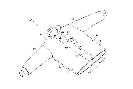
coupling component 74.
[0075] By locating part or all of the magnetic fastener system 72 along the
back of the neck,
and by not placing any magnets, metal, or magnetizable material on the front
of the collar 64, the
user and magnetic fastener system 72 may be more isolated and protected from
front-facing heat
sources. Thus, in one case, the front of the collar 64 and/or the front of the
coat 10 (e.g. in one
case, those portions of the collar 64/body 12 in the front half of the coronal
plane) lacks any
magnetic, magnetizable and/or metallic components, materials or components
and/or lacks any
components that the throat magnetic coupling component 74 can magnetically
interact with to
secure the throat tab 62 in the closed position (e.g. the any magnetic
attraction is not sufficiently
strong to sufficiently secure the throat tab 62 in place).
[0076] In addition, if a magnetic fastening system were to be used to secure
the throat tab 62 in
the closed position, such an arrangement could limit the adjustability of the
throat tab 62; e.g. the
throat tab 62 may only be able to be secured in a single position and/or with
limited adjustability.
Some wearers may want to the throat tab 62 to be secured in looser or tighter
configuration, and
the non-magnetic fastener system 66 provides greater flexibility as described
above.
[0077] With reference to Figs. 20-22, a trouser/boot coupling system 80 can be
utilized to
secure the trousers 56 to one or two boots 82. In particular, in one case the
trousers 56 includes a
first, or trousers, magnetic coupling component 84, which can take the form of
a magnet or
magnetizable portion, that is permanently coupled or secured to the trousers
56, such as by
stitching. The trousers magnetic coupling component 84 can be located at a
lower, distal end of
the trousers 56, at or adjacent to the cuff of the trousers 56, and can be
located on or coupled to
19
Date Recue/Date Received 2023-10-24
an inner surface of the trousers 56 (e.g. not coupled to the outer-facing
surface of the outer-most
layer of the trousers 56 for protection purposes). Fig. 21 shows the trousers
magnetic coupling
component 84 positioned between the outer shell 26 and moisture barrier 28,
but the trousers
magnetic coupling component 84 can be located at any position throughout the
thickness of the
trousers 56, in one case between the outer shell 26 and a wearer of the
trousers 56. The trousers
magnetic coupling component 84 can take the form of a magnet, such as magnet
48 in
combination with the backing plate 50, or the magnet 48 and/or backing plate
50 positioned in
the support strip 46 (see Fig. 21) in the same manner as the magnet systems
described above.
[0078] In one case the trousers magnetic coupling component 84 can be entirely
located in the
lower 5% of the trousers 56, or in the lower 10% of the trousers 56 in another
case, or in the
lower 25% of the trousers 56 in yet another case, or the lower 33% of the
trousers 56 in yet
another case. The trousers magnetic coupling component 84 can be located at
any
circumferential position of the leg of the trousers 56, but in one case is
located on a
circumferential outer surface of the trousers 56 (opposite the inseam) or
within about 15 degrees
thereof. Although Figs. 20-22 show only a single leg of the trousers 56, if
desired both legs of
the trousers 56 can include a trousers magnetic coupling component 84.
[0079] The trousers 56 of Figs. 20-22 may be configured for use with a boot or
boots 82 (or
other footwear) which include a second, or boot, or footwear magnetic coupling
component 86,
which can take the form of a magnet or magnetizable portion which is
permanently coupled or
secured to an inner layer of the boot 82, such as by stitching. In one case
the footwear magnetic
coupling component 86 can be located in about a middle area of height of the
boot 82, and be
located at any circumferential position of the boot 82, but in one case is
located on a
circumferential outer surface of the boot 82 (opposite the instep) or within
about 15 degrees
thereof. In any case, the footwear magnetic coupling component 86 can be
located at a height,
and circumferential position, to be aligned with the corresponding trousers
magnetic coupling
component 84, or vice versa, when the trousers 56 and boots 82 are worn by a
wearer.
[0080] At least one of the trousers 84 or footwear 86 magnetic coupling
components may be a
permanent magnet, while the other one of the associated trousers 84 or
footwear 86 magnetic
coupling component may be either a permanent magnet or a magnetizable
material. Moreover, if
desired, the backing member 50 as described above can be utilized in
conjunction with any
magnets 48 utilized as the trousers 84 or footwear 86 magnetic coupling
components, but if
Date Recue/Date Received 2023-10-24
desired the backing members 50 can be omitted. The trouser/boot coupling
system 80 can utilize
the various features shown and described above with respect to magnet
fasteners systems 40
utilized in other portions of the garment.
[0081] The trousers 84 and footwear 86 magnetic coupling components can
magnetically
interact when the trousers 56 and boots 82 are worn to retain the trousers 56
in place and prevent
the trousers 56 (in particular the legs of the trousers 56) from being pulled
upwardly, thereby
providing protection to the wearer's legs/ankles. The magnetic connection
between the trousers
84 and footwear 86 magnetic coupling components may be able to be manually
overcome by a
wearer to decouple the trousers 84 and footwear 86 magnetic coupling
components, thereby
allowing the trousers 56 and/or boots 82 to be doffed. The trousers/boot
coupling system 80 thus
provide an intuitive, and easy-to-use system for coupling trousers 56 to
footwear 82, with little or
no extra motion required by the wearer to secure or break the connection.
[0082] Having described the invention in detail and by reference to the
preferred embodiments,
it will be apparent that modifications and variations thereof are possible
without departing from
the scope of the invention.
21
Date Recue/Date Received 2023-10-24