Note: Descriptions are shown in the official language in which they were submitted.
WO 2022/236143
PCT/US2022/028204
1
FOOT PAD FOR SUBMERGED MACHINERY
BACKGROUND OF THE INVENTION
1 Field of the Invention
[0001] The present invention relates to devices that can be used to secure
equipment to an
underlying surface or substrate. More particularly, the present invention
relates to such devices
that can be used to secure and remove equipment on submerged surfaces or
substrates.
2. Description of the Prior Art.
[0002] Securing equipment or a machine in a submerged environment can be
difficult. This type
of foundation or anchor, called Foot Pad, is applicable to securing equipment
or a machine on a
submerged rigid surface that includes, but is not limited to, a pipe or tank
wall. This device is
also applicable to securing equipment or a machine on a soft, wet surface that
includes, but is not
limited to, the seafloor, a riverbed, a shallow-water mudflat or bog, or a
permafrost surface.
Surfaces such as these and others, collectively called penetrable substrates
or impenetrable
surfaces, provide little support force per unit area, and without the required
support, equipment
can sink into the substrate or slide off the surface. Furthermore, if a
foundation with a large area
is used, a penetrable substrate can seal the edges of the foundation so that
retrieving the
foundation becomes difficult due to suction forces that develop in the
substrate resisting the
retrieval If a large area foundation is employed for equipment in fast moving
water, the
foundation may offer low shear forces resisting sideways movement of the
equipment and the
foundation and equipment may slide sideways, possibly losing contact with the
substrate.
[0003] A Foot Pad foundation is needed that will provide an adhesion force
holding the
equipment to the substrate, a shear force keeping the Foot Pad and associated
equipment from
sliding or rotating and disengaging with the substrate, and a mechanism to
detach the Foot Pad
from the substrate quickly and efficiently.
SUMMARY OF THE INVENTION
[0004] The Foot Pad described herein is a foundation device that is attached
to a machine and
supports the machine while submerged in a fluid on either an impenetrable
surface or a
penetrable substrate. The Foot Pad is a type of anchor or foundation that can
attach to an
CA 03217980 2023- 11- 3
WO 2022/236143 PCT/US2022/028204
2
impenetrable surface or penetrate a penetrable substrate to a desired depth.
The Foot Pad engages
with the surface and allows the machine to remain stationary to operate as
designed.
[0005] The Foot Pad is an anchor or foundation meant to be installed on an
inpenetrable surface
or to penetrate a penetrable substrate when the Foot Pad is submerged within a
fluid (e.g., in a
tank or water body). The Foot Pad is installed, attached, and/or removed using
a combination of
net underpressure and/or overpressure within one or more of the Foot Pad's
internal volume
chambers bounded by the external components of the device. When compared to
the ambient
fluid pressure outside the device, underpressure is defined as a pressure less
than the ambient
fluid pressure and overpressure is defined as a pressure greater than the
ambient fluid pressure.
The net fluid pressure difference within the Foot Pad compared to ambient
pressure allows the
Foot Pad to conform with, secure to, and/or release from, the submerged
impenetrable or
penetrable substrate. The net underpressure and/or underpressure internal to
the Foot Pad is used
to temporarily attach and detach the Foot Pad from the substrate, providing a
foundation or
footing for a stationary or ambulator machine.
BRIEF DESCRIPTION OF THE DRAWINGS
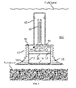
[0006] FIG. 1 - Foot Pad, Elevation, Section View - Default Extension.
[0007] FIG. 2 - Foot Pad, Elevation, Section View - Plenum in low position,
Bellows fully
extended, making first contact with surface of impenetrable surface or
penetrable substrate.
[0008] FIG. 3 - Foot Pad, Elevation, Section View - Plenum retracted to upper
position, Bellows
compressed, Skirt embedded in penetrable substrate.
[0009] FIG. 4 - Foot Pad Bellows, Bottom View.
[0010] FIG. 5 - Foot Pad Bellows, Isometric View.
[0011] FIG. 6 - Foot Pad Bellows, Cross-Section, Showing Stiffening Wires in
Bellows material.
[0012] FIG. 7 ¨ Flexible Diaphragm seal between moving Plenum and Skirt, cut
away elevation
view.
[0013] FIG. 8 ¨Friction Seal between moving Plenum and Skirt, cut away
elevation view.
[0014] FIG. 9 - Equalizer hose connects space inside Skirt with space inside
Bellows and a
single external port allows external control of pressure inside Bellows, cut
away elevation view.
[0015] FIG. 10 ¨ One External Port connects outside fluid to space inside
Bellows, second
External Port connects outside fluid to Equalizer Hose which goes to port on
Plenum, connecting
CA 03217980 2023- 11- 3
WO 2022/236143 PCT/US2022/028204
3
space inside Skirt to outside fluid. Jumper Hose connects the two external
ports, cut away
elevation view.
[0016] FIG. 11 ¨ One External Port connects space inside Pressure Channel to
space inside
Bellows, second External Port connects space inside Pressure Channel to
Equalizer Hose which
goes to port on Plenum, connecting space inside Skirt to fluid in Channel and
on to space inside
Bellows. Channel fabricated on Support Structure connects the two external
ports and provides
for External Port, cut away elevation view.
DETAILED DESCRIPTION OF THE INVENTION
[0017] A Foot Pad [105] of the present invention is illustrated in the
drawings, shown in FIGS.
1-6. The Foot Pad [105] includes a Support Frame [40]; a Skirt [5] with an
Edge [10] that can be
embedded in a substrate; a Bellows [15] with low material stiffness that
captures an under- or
over-pressure between the Bellows and the substrate; an optional Flared
Section [20] at the
bottom of the Bellows [15] with an average cross-sectional area larger than
that of the Bellows
[15]; a Plenum [25] that can move inside the Skirt [5] so as to pump fluid
under the Plenum [25]
into a volume formed by a space between the Plenum [25], the inside wall of
the Skirt [5], and
the substrate; and a Flexible Diaphragm [30] that seals the Plenum [25] to the
Skirt [5], a Hose
[35] that can facilitate fluid movement or pressurization between inside of
the Bellows [15],
Flared Section [20], Skirt [5], and substrate; an Auxiliary Fluid Port [70]
that allows an external
pump to be connected to the space between the Bellows [15] and the Skirt [5].
[0018] FIG. 1 illustrates the Foot Pad [105] in cross-section in elevation
before it interacts with
the impenetrable surface or penetrable substrate. FIG. 2 illustrates the Foot
Pad [105] in cross-
section in elevation once the Bellows [15] or Flared Section [20] interacts
with the impenetrable
surface or penetrable substrate. For an impenetrable surface, the Bellows [15]
and Flared Section
[20] can be used to create a seal and the Skirt [5] provides lateral support
for the Foot Pad [105].
FIG.3 illustrates the Foot Pad [105] installed on a penetrable substrate,
where the Skirt [5]
penetrates the substrate to provide additional lateral support of the Foot Pad
[105].
[0019] The Plenum [25] is secured to one or more Shafts [45] that are driven
up or down relative
to the Skirt [5] and Bellows [15] by a Drive Mechanism [50] external to the
Foot Pad. The Drive
Mechanism [50] may be a hydraulic cylinder, electric cylinder, motor-driven
lead screw or other
mechanism capable of creating vertical force. The Skirt [5] is rigid and can
be made of metal,
CA 03217980 2023- 11- 3
WO 2022/236143 PCT/US2022/028204
4
stiff plastic, or composite materials. The Skirt [5] is of a multi-sided or
cylindrical shape, open at
the bottom or substrate-facing side. The Skirt may have a beveled or formed
Edge [10] at the
substrate-facing edge to facilitate Skirt [5] embedment in a penetrable
substrate. The top of the
Skirt [5] and the Bellows [15] are attached to the Support Frame [40], which
transfers vertical
and horizontal loads to a Connector Structure [65]. The Skirt [5] may vary in
length to develop
uplift resistance through friction between the impenetrable substrate and the
Skirt [5] material,
which uplift resistance enables the Foot Pad [105] to retain equipment of
interest to the surface
or substrate. The Foot Pad [105] is configured to permit change-out of a
different length Skirt
[5]. That is, the length of the Skirt [5] is selectable.
[0020] The Bellows [15] and Flared Section [20] are made of a fiber-
reinforced, natural, or
synthetic rubber. The fiber-reinforcement in the Bellows [15] and Flared
Section [20] may be
natural or synthetic; may be parallel, perpendicular, or diagonal at a variety
of other angles with
the plane of the Plenum [25]; and may be individually laid, woven, or knitted.
The Bellows [15]
may have Stiffeners [60] or stiff hoops at each bend. The Stiffeners [60] may
be made from steel
or composite wire or rods. The Bellows [15] contacts and presses on the
substrate to maintain an
adequate seal with the substrate without embedment (impenetrable surface) or
with minimal
embedment (penetrable substrate) of the Bellows [15]. The optional, larger
average diameter and
larger cross-sectional area Flared Section [20] of the Bellows [15] would
enlarge the footprint of
the Bellows [15] at the substrate surface.
[0021] In the Flared Section [20], the Bellows [15] has circular concentric
ridges that increase
the ability of the flare to form a seal with the impenetrable surface or
penetrable substrate and
may have Radial Channels [55] that allow the pressure differential to be
distributed between the
outer ridges at the ends of the Flared Section [20].
[0022] Fluid can flow, and a pressure differential can be established between
the volume inside
the Skirt [5] and the volume outside the Skirt [5] inside the Bellows [15].
This fluid flow may be
accomplished by using a Hose [35].
[0023] The Plenum [25] is inside the Skirt [5], with a small gap between the
Plenum [25] and the
Skirt [5] to eliminate friction. In one embodiment, as shown in FIG. 7, a
Rolling Diaphragm [30]
fills the gap between the Plenum [25] and the Skirt [5] and creates a pressure
barrier between the
volume above and below the Plenum [25]. When the Plenum [25] is moved toward
the open end
of the Skirt [5], the fluid under the Plenum [25] is pressurized, creating a
downward force on the
CA 03217980 2023- 11- 3
WO 2022/236143 PCT/U52022/028204
impenetrable surface or penetrable substrate and a corresponding upward force
on the Plenum
[25]. When the Plenum [25] is moved away from the open end of the Skirt [5],
the fluid is
depressurized, creating an upward force on the surface or substrate and a
corresponding
downward force on the Plenum [25].
[0024] An alternative embodiment to a Flexible Diaphragm [30] is a metal,
natural rubber, or
synthetic rubber friction Seal [95] to fill the gap between the Plenum [25]
and the Skirt [5], as
shown in FIG. 8, which acts as a pressure barrier between the space inside the
Skirt [5] and the
unpressurized water above the Plenum [25].
[0025] The Foot Pad [105] can withstand vertical compression/extension,
horizontal shear,
overturning moment, and rotational torsion loading from an external source
such as from the
fluid or from the associated Connector Structure [65].
[0026] The Foot Pad [105] is used to support a machine. Multiple Foot Pads can
be configured
onto the machine to provide the necessary stability and functionality of the
machine. The Foot
Pad [105] can supply vertical, horizontal, and rotational reaction forces when
engaged with an
impenetrable surface or penetrable substrate.
[0027] The Foot Pad [105] structural components and the Skirt [5] may be made
of steel or an
aluminum alloy for strength. The Bellows [15] and Flared Section [20] may be
made of natural
rubber or a mix of synthetic and natural rubber, reinforced by Stiffeners [60]
so the Bellows [15]
and Flared Section [20] retain shape when compressed. The Stiffeners [60] may
be made of
metal or composite wire or rods.
[0028] The Skirt [5] length is chosen to match environmental conditions. Where
the Foot Pad
[105] interacts with an impenetrable surface, a short Skirt [5] is used. The
Skirt [5] provides
lateral support to the Bellows [15] and Flared Section [20]. When the Plenum
[25] is retracted
inside the Skirt [5], an underpressure is developed inside the Bellows [15] or
Flared Section [20],
and the Skirt [5] that allows the Bellows [15] or Flared Section [20] to
compress and form a seal
with the impenetrable surface. This attaches the Foot Pad [105] to the
impenetrable surface until
the underpressure is released. Since the Skirt [5] cannot penetrate the
surface the Bellows [15] or
Flared Section [20] is in contact with, the length of the Skirt [5] must be
selected to be long
enough for support but short enough so as not to interfere with compression of
the Bellows [15]
and Flared Section [20] given the ambient fluid pressure and required
underpressure.
CA 03217980 2023- 11- 3
WO 2022/236143 PCT/US2022/028204
6
[0029] Where the Foot Pad [105] interacts with a penetrable substrate, a
longer Skirt [5] is used.
The Skirt [5] will penetrate the substrate and provide lateral support to the
Bellows [15] and
Flared Section [20] and anchoring support and resistance to shear, moment, and
torsional loads
imposed on the Foot Pad [105] from the environment and/or system that is being
anchored by the
Foot Pad [105]. When the Plenum [25] is retracted inside the Skirt [5], an
underpressure is
developed inside the Bellows [15], Flared Section [20], and Skirt [5], which
drives the Skirt [5]
to penetrate the substrate and causes the Bellows [15] or Flared Section [20]
to compress. Fluid
seepage through the penetrable substrate and through the imperfect seal
between the substrate
and the Bellows [15] or Flared Section [20] will serve to decrease the
underpressure. Thus,
motion of the Plenum [25] must be fast enough to create an underpressure that
is sufficient to
embed the Skirt [5] into the substate, but low enough to avoid creating
channels in the substrate
that negate the underpressure. The motion of the plenum [25] and resulting
underpressure can be
adjusted for the substrate type.
[0030] Seepage can occur between the impermeable surface and the Bellows [15]
or Flared
Section [20] because of an irregular shape or seal. Seepage can also occur
between the penetrable
substrate and the Bellows [15] or Flared Section [20] based on the level of
permeability and
porosity of the penetrable substrate to the surrounding fluid under non-
ambient pressures (e.g.,
underpressure or overpressure). If a large enough seepage velocity or force is
established in the
penetrable substrate because of Plenum [25] movement to create underpressure,
the
underpressure may be released. In that case, an auxiliary water pump may be
connected to the
Auxiliary Fluid Port [70] to maintain the underpressure for the duration of
the equipment use, as
shown in FIG 9. The pressure inside the Skirt [5] will be equalized with the
pressure inside the
Bellows [15] by the Hose [35].
[0031] FIG. 10 shows an alternative configuration in which the Hose [35]
attached to a port in
the Plenum [25] connects the space inside the Skirt [5] to an External Port
[75]. An external
Jumper Hose [80] is used to equalize the pressure inside the Skirt [5] and the
pressure inside the
Bellows [15]. The Jumper Hose [80] could include an optional Tee [100] to a
Secondary Pump
Port [90] to allow an external pressure source to control the pressure inside
the Skirt [5] and the
Bellows [15], although that Tee [100] is not a required feature.
[0032] FIG. 11 shows an alternative configuration in which the Hose [35]
connects to the
External Port [75]. A fixed Pressure Channel [85] is fabricated as part of the
Rigid Frame [40]
CA 03217980 2023- 11- 3
WO 2022/236143 PCT/US2022/028204
7
and connects the Auxiliary Fluid Port [70] and the External Port [75], while
also adding an
optional Secondary Pump Port [90] to allow an external pressure source to
control the pressure
inside the Skirt [5] and the Bellows [15], although the Secondary Pump Port
[90] is not a
required feature
[0033] Sideways or lateral movement will be resisted by the Bellows [15]
and/or Flared Section
[20] and the Skirt [5]. When the Bellows [15] or Flared Section [20] is
compressed against either
the impenetrable surface or penetrable substrate, it can oppose sideways
movement by creating a
shear force through friction. When the Skirt [5] is embedded in the penetrable
substate, the Skirt
[5] cross-sectional area will provide additional shear resistance by laterally
loading of the
substrate.
[0034] The Foot Pad [105] can be used with an ambulatory machine. A plurality
of the Foot
Pads [105] would be released from the impenetrable surface or penetrable
substrate, moved, and
reattached at a different location, resulting in a walking motion. This action
requires relatively
quick attachment and retraction, which can be accomplished through timing and
control of the
Plenum [25] in each Foot Pad [105] of a multi-Pad system.
CA 03217980 2023- 11- 3