Note: Descriptions are shown in the official language in which they were submitted.
WO 2022/197337
PCT/US2021/062348
RADIO FREQUENCY FLUID WARMER AND METHOD
Priority Notice
The present application is an International Application of U.S. Non-
Provisional
s Patent
Application No. 17/202,097, filed March 15, 2021, the disclosure of which is
incorporated by reference in its entirety.
Field of the Invention
This present invention relates in general to a system and method for warming
fluids
io using
radio frequency, and more specifically, to a radio frequency fluid warmer and
method
that may be utilized to warm therapeutic fluids.
Background
Warming of fluids has various applications in any number of fields, for
example
is
medicine. In the medical field, warming of fluids is desirable during various
procedures,
particularly in those involving the intravenous administration of fluids to a
patient. This
issue becomes important given that certain fluids vital to patient
resuscitation (such as blood
or blood products) require preservation and storage at low temperatures in
order to prevent
them from spoiling or contamination. Hence administration of such fluids (e.g.
packed red
zo blood
cells) requires warming them in order to avoid causing hypothermia in the
patient
receiving it. Other fluids may require warming prior to being intravenously
infused in a
patient even though said fluids may be stored at room temperature. It is
important to note
that the human body's normal temperature, which is critical to normal
physiologic
homeostasis (typically around 37 degrees Celsius), may be significantly higher
than room
25
temperature. Therefore, exposure of patients (intravenous or any other route)
to therapeutic
fluids that are lower than normal body temperature may not only cause
significant
discomfort, but also have physiologic consequences which can cause adverse
clinical effects
and unwanted outcomes. Accordingly, several systems, apparatus, and methods
are found
in the prior art describing different means to warm fluids such as
refrigerated blood and
30 other
fluids that require intravenous or intraperitoneal administration.
Unfortunately, the
prior art solutions are riddled with numerous problems that have yet to be
properly
addressed.
One common problem is the application of non-uniform electric fields to warm a
therapeutic fluid such as intravenous (IV) fluid, which result in an
inhomogeneous heating
1
CA 03217985 2023- 11- 3
WO 2022/197337
PCT/US2021/062348
of the liquids. Other problems are presented by conduction heating methods,
such as
methods that pass blood through heated conduits, which are energy inefficient,
less portable
and slow, and thus impractical in emergency situations. Other more advanced
methods
include the introduction of microwave heating, but these methods too have been
shown to
s
introduce their own challenges. Primarily, it is now well known that simply
heating fluids
such as blood (i.e. for example by placing a blood bag inside a conventional
microwave
oven) carries unacceptable risks given that heating blood in this manner does
not result in a
uniform distribution of heat throughout the fluid being heated. This important
issue is a
result of the manner in which microwaves are introduced that leads to
generation of
io
hotspots, exposing some areas of the fluid being warmed to excess heat. This
will not only
be undesirable given the non-uniform nature of heating, but can also lead to
adverse effects
such as damage to components of the fluid being warmed (i.e. damage to red
blood cells or
protein structure/function).
While some current methods appear to address hotspots created by systems that
is
implement microwave heating means, these systems appear to rely on components
and
apparatuses that themselves present additional problems; such problems include
introduction of additional steps/equipment (cartridges) in the fluid delivery
apparatus (i.e.
tubing). This disrupts the continuity of the delivery system (by requiring the
tubing to be
connected to a cartridge) and creates points where error and contamination can
occur, hence
zo raising
safety and sterilization concerns. The following examples merely illustrate
some of
the problems found in the prior art.
One application requiring the warming of such fluids prior to administration
includes
the warming of peritoneal dialysis dialysate prior to intraperitoneal
infusion. For example,
certain patients with end-stage renal disease require renal replacement
therapy for survival.
25 One
modality of renal replacement therapy is peritoneal dialysis (PD); a PD
catheter is
placed in the patients' abdomen and dialysates (either sterile solutions
containing fixed
amounts of electrolytes, lactate and dextrose or other infusate such as
lcodextrin) are infused
into the peritoneal cavity. During treatment, the patient's peritoneal
membrane is used as a
dialysis membrane and excess serum electrolytes and toxins are removed via
diffusion into
30 the
dialysate. Given the large volume of dialysates needed each time a patient
fills their
peritoneal cavity (on average between 2.0-2.5L), this fluid is usually warmed
to between
35 C and 37 C to avoid patient discomfort and other unwanted side effects of
hypothermia
given cool fluid is entering the abdomen. The current system used to warm PD
dialysates
relies on heat conduction. The warming process is highly inefficient and is
fraught with
2
CA 03217985 2023- 11- 3
WO 2022/197337
PCT/US2021/062348
excess time and energy wastage. The system requires warming up a large surface
of the
dialysis machine and relies on conduction of this heat to a PD dialysate bag,
which is placed
on top of this surface.
While there are reports of patients/dialysis centers using microwave ovens to
warm
s PD
dialysate fluid, this practice is not sanctioned by the US Food and Drug
Administration
(FDA) or manufacturers of PD solutions, given the potential for formation of
hot spots
during use of conventional microwave ovens. This is in light of the fact that
there are several
reported studies in the literature noting mere exposure to RF energy is safe
and efficient,
and does not lead to disturbance of the PD dialysate content or the integrity
of the bag.
io Several
publications provide discussion of these issues such as "Control of microwave
heating of peritoneal dialysis solutions" by Deutschendorf A F, Wenk R E,
Lustgarten J,
Mason P., appearing in Peritoneal dialysis international: journal of the
International Society
for Peritoneal Dialysis. 1994; 14(2): 163-7; -Microwave ovens for heating
fluid bags for
continuous ambulatory peritoneal dialysis" by Hudson S, Stewart WK, appearing
in British
is medical
journal. 1985; 290(6486):1989; "Rapid warming of infusion solution- by Yamada
Y, Yasoshima A. appearing in Surgery, Gynecology & Obstetrics. 1985; 160(5):
400-2; and
"Microwave warming of peritoneal dialysis fluid." by Armstrong S, Zalatan S J.
appearing
in ANNA journal / American Nephrology Nurses' Association. 1992; 19(6): 535-9;
discussion 40. However, regardless of these reports, significant safety
concerns surrounding
zo hotspot generation and non-uniform warming of dialysate, which can result
in serious
complications, have precluded routine use of general microwave ovens as a
means of
warming peritoneal dialysate.
Another important area where warming of therapeutic fluids is of significant
value
is in critical care when either large volume resuscitation is needed (i.e.
liver transplantation,
23 trauma
from motor vehicle accidents or battlefield injuries) or in the peri-intra-
postoperative
period. In many cases the latter scenarios are interrelated and in all cases
patients can suffer
clinically significant hypothermia. Hypothermia, defined as core temperature
<36 C during
a procedure, is a common problem in critical care and among surgical patients.
In the case
of patients undergoing surgery, an incidence of 4% to 72%, and up to 90% has
been reported.
30
Intraoperative hypothermia has been associated with significant clinical
complications,
including risk of cardiovascular adverse effects, issues with hemostasis and
perioperative
hemorrhage, increased risk of postoperative infection and disturbed drug
metabolism. Given
these significant complications, many professional societies, such as the
Association of
periOperative Registered Nurses (AORN), www.aorn.org, and the National
Institute for
3
CA 03217985 2023- 11- 3
WO 2022/197337
PCT/US2021/062348
Health and Care Excellence (NICE), www.nice.nhs.uk, have recommendations in
place for
preventing and treating during the perioperative period. While there are many
factors which
may contribute to hypothermia the use of un-warmed fluids for intravenous
infusion has
been deemed to play a major role. While the positive effects of normothermia
in these
s
patients has been documented, the role of warming of patients or infused
fluids has been
mainly studied using incubators and convection methods. "The effects of
warming
intravenous fluids on intraoperative hypothermia and postoperative shivering
during
prolonged abdominal surgery" by Camus Y, Delva E, Cohen S, Lienhart A
published in
Acta Anaesthesiol Scand. 1996 Aug;40(7):779-82. "The effects of intravenous
fluids
io
temperature on perioperative hemodynamic situation, post-operative shivering,
and
recovery in orthopaedic surgery" by Hasankhani H, Mohammadi E, Moazzami F,
Mokhtari
M, Naghgizadh MM. published in the journal Can Oper Room Nurs J. 2007
Mar;25(1):20-
4, 26-7. Again, these methods are fraught with inefficiency, lack of
portability and excess
time requirement. Therefore, novel fluid warming technologies which can
address
is
hypothermia in the scenarios mentioned will be of significant value. The
application of
microwave technology has been limited and will be discussed in the next
section.
Another important application involves the need for warming of blood and blood
products (red blood cell transfusion); a treatment which becomes necessary to
maintain the
oxygen-carrying capacity in patients with severe anemia, especially those who
have suffered
20 major
trauma or patients undergoing major surgery. During resuscitation of the
latter
patients, multiple units of blood products or packed red blood cells (PRBCs)
may be
administered in a short period of time. Such products or PRBC units are
normally
refrigerated at low temperatures of 4 2 C prior to transfusion. The FDA
regulation
recommends storage temperature in the range of 1 C ¨ 6 C; "Safe storage" would
be
25
considered to be void if the temperature exceeds 8 C. (See for example FDA
"Guide to
inspections of blood banks," published by the FDA, Office of Regulatory
Affairs
Washington. 14th Sep. 1994).
For patients requiring large volumes of blood transfusion, to prevent
hypothermia,
the PRBCs units must be warmed up rapidly and almost immediately before
transfusion.
30 Aside
from the inherent energy inefficiency of convection heating methods, using
known
means that implement conduction, could prove problematic; especially in
emergency
situations where considerable transfusions are required to be infused rapidly.
Although delays resulting from heating means relying on conduction of heat
appeared to have been addressed by microwave heating methods, these systems
proved
4
CA 03217985 2023- 11- 3
WO 2022/197337
PCT/US2021/062348
similarly problematic. The use of conventional microwave ovens or other
adapted
derivatives to warm blood and IV products became popular soon after the
introduction of
commercial microwave ovens in the mid-1950s and was regularly used up until
the 1970s.
Such devices offer shorter heating times than the convectional heaters such as
those using a
s water
bath, but several reports of complications from overheating of blood products
led to
abandonment of microwave oven blood warmers. See for example "Danger of
overwarming
blood by microwave" by Arens J F, Leonard GL published in Jarna. 1971; 218(7):
1045-6.
Considerable ongoing debates remain regarding the use of these devices (see
for example,
"Indicators of erythrocyte damage after microwave warming of packed red blood
cells" by
lc) Hirsch
J, Menzebach A, Welters ID, Dietrich GV, Katz N, Hempelmann G. published in
Clinical chemistry. 2003; 49(5): 792-9; and "Temperature course and
distribution during
plasma heating with a microwave device" by Hirsch J, Bach R, Menzebach A,
Welters I D,
Dietrich G V. Hempelmann G. published in Anesthesia 2003; 58(5): 444-7).
There are several reports that describe the use of various microwave-based
is
techniques to warm blood products, which do not involve heating up a blood bag
inside a
microwave oven, per se. However, each of these methods is complicated by an
apparent
inability to avoid hot spots, or use techniques that require the use of a
disposable cartridge.
The former having the potential to damage or inadequately heat up the fluids;
the latter
introducing a point of disruption in the delivery of the infusate which can
create the potential
20 for
clinically significant adverse events such as entry of air, contaminants or
infection given
that the need for a cartridge breaks the continuous sterile transfusion system
(i.e. the tubing
connecting the infusate to the patient). In addition, the need for a cartridge
adds another
layer of cost and complexity which is less desirable. (See for example.
"Microwave
applications in clinical medicine" by Lantis J C, 2nd, Carr K L, Grabowy R,
Connolly R J,
25
Schwaitzberg S D. published in Surgical endoscopy. 1998; 12(2): 170-6; -The
limits of
bloodwarming: maximally heating blood with an inline microwave blood warmer"
by
Herron D M, Grabowy R, Connolly R, Schwaitzberg S D. published in The Journal
of
trauma, 1997; 43(2): 219-26; discussion 26-8; "In-line microwave blood warming
of in-date
human packed red blood cells- by Pappas CG, Paddock H, Goyette P, Grabowy R,
Connolly
30 R J,
Schwaitzberg S D. published in Critical care medicine, 1995; 23(7): 1243-50;
"The
effect of in-line microwave energy on blood: a potential modality for blood
warming" by
Holzman S. Connolly R J, Schwaitzberg SD. published in The Journal of trauma.
1992;
33(0:89-93; discussion -4; and "Rapid in-line blood warming using microwave
energy:
preliminary studies." By Schwaitzberg S D, Allen M J, Connolly R J, Grabowy
RS, Carr K
CA 03217985 2023- 11- 3
WO 2022/197337
PCT/US2021/062348
L, Cleveland RJ. published in Journal of investigative surgery: the official
journal of the
Academy of Surgical Research. 1991; 4(4):505-10).
Accordingly, there is an unanticipated and significant clinical need, which is
inadequately addressed at this time for warming fluids. More specifically,
there is a need
s in the art for a fluid warming technique whereby fluids, such as
intravenous (IV) fluids, can
be warmed to the desired temperature via a warmer apparatus that avoids the
potential
complications of localized overheating, or exposure to hot-spots altogether.
Furthermore,
there is a need for a fluid warming technique and apparatus that is more
portable and does
away with cartridges or components that break a closed sterilized system,
minimizing risk
to of error or infection and avoiding safety and sterilization challenges
presented by current
means.
Therefore, there is a need in the art for a radio frequency fluid warmer and
method
that may be utilized to warm fluids, including IV fluids, which adequately
addresses the
problems with the prior art. It is to these ends that the present invention
has been developed.
is
Summary of the Invention
To minimize the limitations in the prior art, and to minimize other
limitations that
will be apparent upon reading and understanding the present specification, the
present
invention describes a radio frequency fluid warmer and method that may be
utilized to warm
20 therapeutic fluids.
A radio frequency fluid warmer apparatus, in accordance with an exemplary
embodiment of the present invention, comprises: a waveguide including first
and second
electromagnetic ports, an inlet for receiving a fluid, and an outlet for
dispensing the fluid; a
tube for routing the fluid inside the waveguide between the inlet and the
outlet during
25 operation of the apparatus; a source of electromagnetic energy coupled
to the first
electromagnetic port; and a termination coupled to the second electromagnetic
port for
preserving a matched waveguide condition.
A radio frequency fluid warmer apparatus, in accordance with another exemplary
embodiment of the present invention, comprises: a waveguide including first
and second
30 electromagnetic ports, an inlet, and an outlet for receiving a fluid
tube that traverses the
waveguide; a pathway situated inside the waveguide for routing the fluid tube
between the
inlet and the outlet; a radio frequency generator coupled to the first
electromagnetic port;
and a termination coupled to the second electromagnetic port for preserving a
matched
waveguide condition.
6
CA 03217985 2023- 11- 3
WO 2022/197337
PCT/US2021/062348
A system for warming intravenous fluids using radio frequency signals, in
accordance with an exemplary embodiment of the present invention, comprises: a
rectangular waveguide including first and second electromagnetic ports, an
inlet situated
substantially at a sidewall of the rectangular waveguide for receiving a
fluid, and an outlet
s for
dispensing the fluid; a control module configured to: generate radio frequency
signals
from an energy source; and apply the radio frequency signals to the first
electromagnetic
port; a tube for routing the fluid inside the rectangular waveguide between
the inlet and the
outlet during operation of the system; and a termination coupled to the second
electromagnetic port for preserving a matched waveguide condition.
io A radio
frequency fluid warmer system, in accordance with the present invention,
may include: a waveguide including first and second electromagnetic ports, an
inlet, and an
outlet for receiving a fluid-carrying tube that traverses the waveguide; a
radio frequency
generator coupled to the first electromagnetic port; a resistive termination
coupled to the
second electromagnetic port for preserving a matched waveguide condition; and
a control
is module
in communication with one or more sensors situated in proximity to the inlet
and
outlet of the waveguide, the control module configured to: monitor a
temperature of the
fluid inside the fluid-carrying tube based on sensing data of the one or more
sensors; and
control a power level of the radio frequency generator in response to the
sensing data.
A method performed by radio frequency fluid warmer system, in accordance with
zo the
present invention, may include the steps of: controlling a power level of a
radio
frequency generator coupled to a first electromagnetic port of a waveguide,
wherein the
waveguide includes a resistive termination coupled to a second electromagnetic
port of the
waveguide for preserving a matched waveguide condition, and wherein the
waveguide is
adapted to receive a fluid-carrying tube positioned between an inlet and an
outlet of the
25
waveguide; receiving sensing data from one or more sensors situated in
proximity to the
inlet or the outlet of the waveguide; and monitoring a parameter of a fluid
inside the fluid-
carrying tube based on sensing data from the one or more sensors.
It is an objective of the present invention to provide an RF frequency fluid
warming
device that avoids hot-spots.
30 It is another objective of the present invention to uniformly warm
fluids.
It is yet another objective of the present invention to provide a fluid
warming device
which does not require any additional supplemental equipment (such as a
cartridge) and
does not disrupt the continuity of the fluid deliver system.
7
CA 03217985 2023- 11- 3
WO 2022/197337
PCT/US2021/062348
It is yet another objective of the present invention to provide a compact,
energy
efficient, transportable fluid warming device.
These and other advantages and features of the present invention are described
herein with specificity so as to make the present invention understandable to
one of ordinary
s skill in the art.
Brief Description of the Drawings
Elements and embodiments in the figures have not necessarily been drawn to
scale
in order to enhance their clarity and improve understanding of the invention.
Furthermore,
elements that are known to be common and well understood to those in the
industry are not
depicted in order to provide a clear view of the various embodiments of the
invention.
FIG. 1 depicts a formation of hot-spots, which may be found in a typical
microwave
cavity (such as the inside of a microwave oven), illustrating a common problem
of using
microwaves to heat certain types of fluids.
FIG. 2(a) and FIG. 2(b) illustrate an exemplary rectangular waveguide field
pattern
in accordance with practice of the present invention.
FIG. 3 illustrates a top cross-sectional view of a rectangular waveguide
showing an
exemplary pathway in which a fluid tube may be positioned, in accordance with
an
exemplary embodiment of the present invention.
FIG. 4 illustrates a system for warming fluids in accordance with an exemplary
embodiment of the present invention.
FIG. 5(a) illustrates a fluid warming apparatus for a system for warming
fluids in
accordance with an exemplary embodiment of the present invention.
FIG. 5(b) illustrates a cross-sectional top view of the apparatus illustrated
in FIG.
5(a).
FIG.6(a) illustrates a top cross-sectional view of a fluid warming system in
accordance with an exemplary embodiment of the present invention.
FIG. 6(b) illustrates a front view of the fluid warming system depicted in
FIG. 6(a).
FIG. 6(c) illustrates a rear view of the fluid warming system depicted in FIG.
6(a).
FIG. 6(d) illustrates a side cross-sectional view of the fluid warming system
depicted in FIG. 6(a).
FIG. 7 is a diagram showing an exemplary pathway of a fluid-carrying tube
inside
a waveguide with corresponding energy intensity therethrough, in accordance
with an
exemplary embodiment of the present invention.
8
CA 03217985 2023- 11- 3
WO 2022/197337
PCT/US2021/062348
FIG. 8 is a graph showing attenuation versus length increments, which
illustrates
absorption rate along the length of an intravenous fluid-carrying tube.
FIG. 9 illustrates a screenshot of an analysis tool showing infusion tube
losses,
without liquid.
FIG. 10 illustrates a screenshot of an analysis tool showing infusion tube
losses,
with liquid.
FIG. 11 illustrates a system for warming fluids in accordance with an
exemplary
embodiment of the present invention.
FIG. 12A illustrates a flow chart of a method for warming fluids performed by
a
to system in accordance with an exemplary embodiment of the present
invention.
FIG. 12B illustrates a flow chart of a method for executing a heating phase
performed by a control module in accordance with the present invention.
FIG. 12C illustrates a flow chart of a method for continuously monitoring and
controlling a temperature of a fluid performed by a control module in
accordance with the
is present invention.
FIG. 12D illustrates a flow chart of a method for warming fluids performed by
a
system in accordance with an exemplary embodiment of the present invention.
Detailed Description of Exemplary Embodiments
20
In the following discussion that addresses a number of embodiments and
applications of the present invention, reference is made to the accompanying
drawings that
form a part thereof, where depictions are made, by way of illustration, of
specific
embodiments in which the invention may be practiced. It is to be understood
that other
embodiments may be utilized, and changes may be made without departing from
the scope
23 of the invention. Wherever possible, the same reference numbers
are used in the drawings
and the following description to refer to the same or similar elements.
In the following detailed description, numerous specific details are set forth
by way
of example in order to provide a thorough understanding of the relevant
teachings. However,
it should be apparent to those skilled in the art that the present teachings
may be practiced
30 without such details. In other instances, well known structures,
components and/or
functional or structural relationships thereof, etc., have been described at a
relatively high-
level, without detail, in order to avoid unnecessarily obscuring aspects of
the present
teachings_
9
CA 03217985 2023- 11- 3
WO 2022/197337
PCT/US2021/062348
Throughout the specification and claims, terms may have nuanced meanings
suggested or implied in context beyond an explicitly stated meaning. Likewise,
the phrase
"in one embodiment/example" as used herein does not necessarily refer to the
same
embodiment and the phrase "in another embodiment/example" as used herein does
not
s
necessarily refer to a different embodiment. It is intended, for example, that
claimed subject
matter include combinations of example embodiments in whole or in part.
Conditional language used herein, such as, among others, "can," "could,"
"might,"
"may," "e.g.," and the like, unless specifically stated otherwise, or
otherwise understood
within the context as used, is generally intended to convey that certain
embodiments include,
to while
other embodiments do not include, certain features, elements and/or steps.
Thus, such
conditional language is not generally intended to imply that features,
elements and or steps
are in any way required for one or more embodiments, whether these features,
elements
and/or steps are included or are to be performed in any particular embodiment.
The terms "comprising." "including," "having," and the like are synonymous and
is are
used inclusively, in an open-ended fashion, and do not exclude additional
elements,
features, acts, operations and so forth. Also, the term "or" is used in its
inclusive sense (and
not in its exclusive sense) so that when used, for example, to connect a list
of elements, the
term "at' means one, some, or all of the elements in the list. Conjunctive
language such as
the phrase "at least one of X, Y, and Z," unless specifically stated
otherwise, is otherwise
zo
understood with the context as used in general to convey that an item, term,
etc. may be
either X, Y, or Z. Thus, such conjunctive language is not generally intended
to imply that
certain embodiments require at least one of X, at least one of Y, and at least
one of Z to each
be present. The term "and or" means that "and" applies to some embodiments and
"or"
applies to some embodiments. Thus, A, B, and or C can be replaced with A, B,
and C
25 written
in one sentence and A, B, or C written in another sentence. A, B, and or C
means
that some embodiments can include A and B, some embodiments can include A and
C, some
embodiments can include B and C, some embodiments can only include A, some
embodiments can include only B, some embodiments can include only C, and some
embodiments include A, B, and C. The term "and or- is used to avoid
unnecessary
30
redundancy. Similarly, terms, such as "a, an," or "the," again, may be
understood to convey
a singular usage or to convey a plural usage, depending at least in part upon
context. In
addition, the term "based on may be understood as not necessarily intended to
convey an
exclusive set of factors and may, instead, allow for existence of additional
factors not
necessarily expressly described, again, depending at least in part on context.
CA 03217985 2023- 11- 3
WO 2022/197337
PCT/US2021/062348
While exemplary embodiments of the disclosure may be described, modifications,
adaptations, and other implementations are possible. For example,
substitutions, additions,
or modifications may be made to the elements illustrated in the drawings, and
the methods
described herein may be modified by substituting, reordering, or adding stages
to the
s
disclosed methods. Thus, nothing in the foregoing description is intended to
imply that any
particular feature, characteristic, step, module, or block is necessary or
indispensable.
Indeed, the novel methods and systems described herein may he embodied in a
variety of
other forms; furthermore, various omissions, substitutions, and changes in the
form of the
methods and systems described herein may be made without departing from the
spirit of the
lo
invention or inventions disclosed herein. Accordingly, the following detailed
description
does not limit the disclosure. Instead, the proper scope of the disclosure is
defined by the
appended claims.
Generally, the present invention involves an in-line real-time radio frequency
apparatus for warming fluids, including but not limited to IV fluids. In
exemplary
is embodiments, an in-line heating or warming of fluids may be achieved by
means of
exposing a fluid having all initial temperature to Radio Frequency (RF)
energy. The RF
energy may be supplied by an appropriately configured, digitally controlled,
RF generator
that generates the RF energy into a containment vessel or waveguide. The
waveguide
typically includes a first terminal end including a point of entry into which
a fluid tube may
zo be
introduced, and a second terminal end from which the fluid tube may exit the
waveguide.
Inside the waveguide, a pathway may be formed wherein the fluid tube may rest
in a
predetermined position. In exemplary embodiments, the pathway guides the
positioning of
the tube along a transmission-line length of the waveguide, in a manner such
that the tube
gradually approaches an electromagnetic field inside the waveguide and exits
at the second
25
terminal end of the waveguide. The fluid inside the tube, having been
gradually exposed to
the RF energy inside the waveguide, may absorb energy at a substantially
constant rate per
unit length, and exit the waveguide at a temperature higher than the fluid's
initial
temperature. The apparatus is typically non-invasive and may be constructed
using a
suitable high-frequency transmission-line structure such as a rectangular,
circular or
30
elliptical waveguide operating in an appropriate mode of propagation. In
exemplary
embodiments, the in-line exposure to RF energy is substantially along the
transmission-line
length, and in a manner, which prevents unsafe over-exposure and overheating
of the fluid
as it traverses through the warming apparatus, by for example, implementing a
gradual and
predefined coupling rate of RF energy to the fluid-carrying tube along the
transmission-line
11
CA 03217985 2023- 11- 3
WO 2022/197337
PCT/US2021/062348
length. In exemplary embodiments, a non-invasive temperature monitoring
subsystem may
be employed for monitoring the temperature of the liquid flowing in the tube.
Automatic
fail-safe controls may comprise of an "operator watch" safety-check to prevent
operator
errors. Moreover, inlet and outlet temperatures may be continuously sampled to
monitor
s and
control the power level of applied RF energy to the waveguide, in order to
achieve the
desired temperature while avoiding over or under heating.
In the present specification, the term fluid may refer to, but is not limited
to, IV
fluids, dialysates, blood or blood products, replacement fluids for continuous
renal
replacement therapy (CRRT), dialysis water, or any other fluid or therapeutic
fluid that may
io be
administered to a patient. For example, and without limiting the scope of the
present
invention, fluids in this disclosure may refer to various concentrations of
saline, lactated
ringer, D5W, blood products (including but not limited to packed red blood
cells, fresh
frozen plasma, platelets and cryoprecipitate), peritoneal dialysis dialysate,
hemodialysis
dialys ate/water, continuous renal replacement therapy replacement fluid and
dialysates,
is
plasmapheresis and plasma exchange blood products prior to use in patients, or
any other
fluids including fluids that may require warming prior to or concurrent with
medical
procedures. Of course, a person of ordinary skill in the art will appreciate
that other fluids,
including fluids that may not necessarily have therapeutic properties, may be
warmed or
heated using an apparatus in accordance with the present invention.
20 An
apparatus in accordance with present invention is entirely different from the
methodologies previously disclosed in the prior art and avoids the
shortcomings of the
previous systems. To illustrate the problems addressed by a system in
accordance with the
present invention, a brief detailed examination of microwave technology
explains the causes
for concerns with application of devices or any adapted derivatives that
employ RF energy
25 as a
means to warm fluids, particularly IV fluids. To such ends, and now turning
the first
figure, FIG. 1 depicts a formation of hot-spots, which may be found in a
typical microwave
cavity (such as the inside of a microwave oven), illustrating a common problem
of using
microwaves to heat certain types of fluids.
More specifically, FIG. 1 shows the energy distribution in a microwave cavity
or
30
resonator is not uniform, and the temperature of the target (for example a
fluid-containing
bag) at hotspots (i.e. the dark spots) can easily exceed safe limits. Based on
the below
analysis, the application of any cavity-based microwave ovens regardless of
configuration
should be considered as potentially unsafe. This analogy can be extended to
any enclosed
cavity system that may be used to warm or heat certain fluids, including IV
fluids.
12
CA 03217985 2023- 11- 3
WO 2022/197337
PCT/US2021/062348
A microwave oven in its simplest form comprises of a continuous wave (CW) or
pulsed RF source at the 2.45GHz range. In microwave ovens, the RF source is
normally a
magnetron which is a high-power high-frequency tube oscillator. Recently,
solid state
sources are becoming available for such applications. The RF generator is
coupled to the
s microwave cavity or warming cavity. A short section of metallic waveguide
connects the
RF generator to the warming cavity. The applied RF energy excites a cavity
mode in the
warming cavity. The formation of a cavity mode is due to propagation of
electromagnetic
waves between the walls of the enclosed cavity leading to the formation of a
standing wave
pattern with peaks (nodes) and troughs (antinode), wherein the nodes are hot-
spots such as
to those seen in FIG. 1.
The following explains the causes of hot spot formation inside a microwave
cavity.
The RF electric field component inside the cavity may be given as follows:
Er = E1 cos(icxx) sin(kyy) sin(k,z) 8jt, (1);
Ey E2 sin(ic,x) cos(kyy) sin(k,z) t ,
(2); and
15 E = E3 sin(kx.x) sin(kyy) cos(k,z) et, (3),
where to is the angular frequency of the microwave, and Icx, k3, and kr, are
given by:
1717T nit k = ¨' k = k =it
and m,n,p = 0, 1, 2, ..., (4),
x L.õ Y Ly L,
where Lx, Lo, and L are dimensions of the cooking cavity, and E1, E) and Eg
are
constrained by:
20 kx=Ei kyE2 k7E3 = 0, (5), and
the average power density absorbed by a load in the microwave (e.g. food) may
be given as:
< P > < E2 > , (6),
where < E2 = 1 x (1E 12 1E 12 iEzi2),
2 (7).
Given suitable values of m, n and q which are a function of cavity size, a
typical power
23 distribution may be as shown in FIG. 1. Thus, this shows that an RF
cavity structure that
generates a standing-wave pattern for RF heating inside an enclosed warming
cavity will
have hot-spots. Standing-waves are generated when the energy travels in two
opposing
directions, which occurs when the RF energy is bounced back and forth by
reflective
(metallic) cavity walls. Therefore, to achieve uniform heating inside a
waveguide, the
30 formation of standing waves must be avoided.
Accordingly, the present invention provides for uniform RF heating by
implementing a system that instead generates a travelling wave when applying
RF energy
13
CA 03217985 2023- 11- 3
WO 2022/197337
PCT/US2021/062348
to the system's waveguide. As will be discussed in turn with reference to the
remaining
figures, by facilitating the formation of a travelling wave heating structure
including a
waveguide that is appropriately matched at its terminals, the present
invention enables an
efficient, quick heating means of warming fluids in a uniform and homologous
manner.
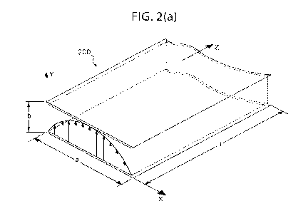
Turning now to the figures depicting the invention, FIG. 2(a) and FIG. 2(b)
illustrate an exemplary rectangular waveguide field pattern in accordance with
practice of
the present invention. More specifically, FIG. 2(a) and FIG. 2(b) illustrate a
diagram that
helps explain the coupling of energy from a waveguide 200 to a fluid-carrying
tube (not
shown in this figure), utilizing a specific property of electric field pattern
generated inside
waveguide 200.
As mentioned above, waveguide 200 in accordance with an exemplary embodiment
of the present invention may include any number of structural designs, and may
comprise
of a rectangular waveguide as shown having a length L, a width a, and a height
b; however,
this particular geometry is not a limiting case and other geometries with
similar field patterns
is are equally appropriate, including circular or elliptical cross-
sections, and variations such as
ridged waveguides and others would not deviate from the scope of the present
invention.
Waveguide 200 is shown as a substantially rectangular structure, in accordance
with
an exemplary embodiment of the present invention, having an electric field
generated
perpendicular (along height b) to the direction of propagation (along length
L) through
waveguide 200; as shown, the dominant transverse electric (TE) mode waveguide
200 is in
TEio. In this mode of excitation, the peak of envelope 201 of electric field
202 is half sine
in shape, i.e. the field intensity is maximum at the center of waveguide 200's
broad
dimension (width a) and its intensity decreases to zero approaching each of
the waveguide
side walls 204. Accordingly, in order to tap the maximum energy from waveguide
200, a
fluid-carrying tube may be placed at the center of waveguide 200, meaning
positioning the
tube at substantially half a and along length L of waveguide 200. Conversely,
to minimize
the energy absorption of a fluid introduced into waveguide 200, a fluid-
carrying tube may
be placed closer to the side walls 204. Consequently, as shown in FIG. 2(a)
and FIG. 2(b),
the location of the fluid-carrying tube (e.g. an IV tube) in waveguide 200
will determine the
amount of energy absorption by the fluid-carrying tube.
It should be noted that while the current disclosure focuses on a rectangular
waveguide propagation in TEio mode of operation, other geometries and
supporting modes
may be utilized without deviating from the scope of the present invention.
14
CA 03217985 2023- 11- 3
WO 2022/197337
PCT/US2021/062348
For example, the envelope of the field intensity across the cross section of a
rectangular waveguide can be calculated analytically or simulated using
numerical
techniques. Such techniques are well known to those skilled in the art. As
depicted by the
plot of electric field pattern illustrated in FIG. 2, the electric field
envelop peaks across the
s
waveguide' s cross section; showing a half sinusoidal variation across the
broad dimension
of waveguide 200. If a waveguide is excited at its TED) mode, a similar
analysis will show
a full sinusoidal variation and the electric filed will peak twice across the
waveguide
opening. Accordingly, both TEm and TE20 can be utilized for the intended
application. As
an example, however, and in no way intended to limit the scope of the present
disclosure,
io this specification focuses on the TEm mode as an illustrative
embodiment.
As such, in an exemplary embodiment of the present invention, the available RF
energy peaks at the center of the broad dimension or width a (as shown in FIG.
2(a) and
2(b)) and the intensity reduces near the sidewalls. Therefore, if a fluid
carrying tube is
placed along the length L of waveguide 200 (i.e. within a pathway, for
example), the RF
is energy
will interact with the fluid in the tube and the energy absorption rate will
be a
function of location of the tube within the waveguide's cross-section, so
that, with reference
to FIG. 2(a) and 2(b) for example, the absorbed energy is a function of x (or
a width along
the length of the waveguide). The following figure illustrates such
embodiment.
Turning now to the next figure, FIG. 3 illustrates a top view of a rectangular
20
waveguide showing an exemplary cavity, conduit, or pathway in which a fluid
tube may be
positioned, in accordance with an exemplary embodiment of the present
invention. More
specifically, waveguide 300 is shown comprising a housing or clam shell, which
includes a
first shell 301 and a second shell 302, that may be decoupled from each other
so that one of
the shells acts as a top shell that encloses or envelops portions of a base
shell.
25 In
exemplary embodiments, as will be discussed further below with reference to
other figures, the top shell is substantially hollow and the base shell (for
example, second
shell 302) may be filled with a foam structure 302a that is lightweight but
allows for the
formation of a cavity, conduit or pathway 303 in which to position a fluid
tube, such as an
IV fluid tube. In the embodiment shown, depicted in a cross-sectional top
view, it can be
30
appreciated that the insertion of a tube positioned within pathway 303, which
runs along the
length or the z-axes of waveguide 300, will alter the hallow waveguide
structure in terms of
RF energy conduction. As mentioned above, the location of a fluid-carrying
tube along
pathway 303 will determine the amount of energy absorption or heat generated
in the fluid-
carrying tube.
CA 03217985 2023- 11- 3
WO 2022/197337
PCT/US2021/062348
In exemplary embodiments, waveguide 300 is a partial dielectric-filled
waveguide.
As a person of ordinary skill in the art will appreciate, power loss (and
conversion to heat)
in a waveguide transmission-line is caused by imperfection of wall conductors
and the
dielectric filling the waveguide. Therefore, input RF power may be gradually
attenuated as
s the
input RF signal travels along the guide between RF input port 307 and
terminated port
308. The attenuation factor for a transmission-line in may be defined as:
Power lost in unit length
a= __________________________________________________________ (8),
2 xpower transnuttea
where: a = ac + ad; ac= the attenuation factor due to the walls' ohmic
resistance; and
ad= the dielectric loss per unit length.
lo In an air-filled waveguide (i.e. without a tube inserted), the ac >>
ad. However,
when the fluid-carrying tube is inserted in the waveguide, the waveguide gets
loaded and
the dielectric loss will dominate, i.e., occ ad in which case the fluid (i.e.
inside the
fluid-carrying tube) absorbs the RF energy and heats up. This is shown in FIG.
9 ¨ FIG.
10.
s The signal attenuation caused by fluid absorption may he calculated
from:
insertion loss = 10loge2al (9),
where oc is the combined loss-coefficients and is dominated by ad. The ad is
the attenuation
factor of loss caused by the tube and the fluid. FIG. 9 shows that the tube
loss (with no
fluid) is negligibly small whereas the flow of fluid in the tube constitutes
the dominant share
20 of loss
(ad) as shown in FIG. 10, which is caused by absorption of RF energy and
heating
the fluid in the tube.
Accordingly, it is noted that the insertion loss of a fluid-carrying tube, or
a loaded
waveguide. is proportional to the length 1 where the fluid-carrying tube
interacts with the
electric field in the waveguide. As discussed earlier, the RF heating would be
maximum if
25 the
tube is always located at the center of the guide, and the heating rate (i.e.
heat generated
per unit length) will be highest closer to the RF source or RF input port 307,
and lowest
closer to the terminated port 308, which is situated at a low intensity RF
section of
waveguide 300.
However, a fluid warming apparatus in accordance with the present invention
30
preferably, especially for applications involving certain medical fluids,
includes a pathway
positioned such as pathway 303, which gradually veers away from side-walls 304
towards
a center portion of waveguide 300.
16
CA 03217985 2023- 11- 3
WO 2022/197337
PCT/US2021/062348
In such embodiment, for TE/0 mode, the attenuation factor ad will be modified
by
term (where for TE10, m=1 and n=0). Here "x" (see FIG. 2. FIG. 3) is the
variable that defines the tube location across length L of the waveguide. For
example, for
x=0 at (waveguide wall, or for example waveguide inlet opening 306) the
dielectric
attenuation (attenuation factor ad) is reduced to zero and no heat is
generated assuming
dominant ad as discussed above. The attenuation (absorption) will be maximum
at x =
(i.e., at the center of the front wall of the waveguide that includes the
inlet).
The following Table 1.0 discloses an exemplary means for a uniform
distribution of
heat along the length of waveguide 300. Of course, this is shown by way of
example and
io in no
way is Table 1.0 intended to limit the scope of the present invention.
Assuming a
typical waveguide construction for waveguide 300, wherein a fluid-carrying
tube has been
positioned along pathway 303, and wherein L is 20 cm, the absorption rate in
each increment
of Al = 1 cm may exemplarily follow the Table 1.0 below, in order to achieve a
uniform
heat generation.
is
Tube length increments Input power level at each increment
Power absorbed in each increment Power absorbed dB
1 100 0.05 -
13.01029996
2 95 0.052631579 -
12.78753601
3 90 0.055555556 -
12.55272505
4 85 0.058823529 -
12.30448921
5 80 0.0625 -
12.04119983
6 75 0.066666667 -
11.76091259
7 70 0.071428571 -
11.46128036
8 65 0.076923077 -
11.13943352
9 60 0.083333333 -
10.79181246
55 0.090909091 -10.41392685
11 50 0.1 -10
12 45 0.111111111 -
9.542425094
13 40 0.125 -
9.03089987
14 35 0.142857143 -
8.4509804
30 0.166666667 -7.781512504
16 25 0.2 -
6.989700043
17 20 0.25 -
6.020599913
18 15 0.333333333 -
4.771212547
19 10 0.5 -
3.010299957
5 1 3.85731E-15
Table 1.0
17
CA 03217985 2023- 11- 3
WO 2022/197337
PCT/US2021/062348
More specifically, Table 1.0 above shows the RF energy absorption rate along
the
length of waveguide for uniform heat generation; this may be plotted as shown
in FIG. 8.
Referring to equation (7), the RF energy is given as:
P cc < E2 > = = E2sin2 (Lx) (10),
2tITE 2t/TE a
where "a" is the broad dimension of waveguide 300 and "x" is the location of
the fluid-
carrying tube across the waveguide's length L, and power "P" is constant per
unit length
along the waveguide length L.
Turning now to the next figure, FIG. 4 illustrates a system for warming fluids
in
accordance with an exemplary embodiment of the present invention. More
specifically,
io FIG. 4
depicts an RF fluid warmer system (system 400), which comprises: waveguide
401;
an RF source control module (control module 402); an RF input line 403 that
introduces RF
signals into waveguide 401 via a first electromagnetic port or RF input port
404; a
termination comprising terminal port 405 connected to an RF connector 406,
which collects
any unabsorbed portion of the input power and dumps it in a matched load; and
temperature
is sensors
407 and 408 situated at input terminal end 409 and output terminal end 410,
respectively, for non-invasively measuring (and enabling temperature
monitoring and
control via control module 402) the temperature of the fluid entering and
exiting waveguide
401. As in previous figures, waveguide 401 is also shown from a top cross-
sectional view
in which the interior portion of the containment vessel or waveguide 401 can
be appreciated.
zo As
shown, waveguide 401 typically includes a structure such as foam structure
411, which
includes a pathway 412 (similar to pathway 303 in FIG. 3, for example) that
facilitates the
positioning, or guides, fluid-carrying tube 412a. Furthermore, waveguide 401
includes two
clamps 413 that hold the two halves of the containment vessel or housing of
waveguide 401
together after the insertion of the tube and while the apparatus is
operational.
25 The
exemplary embodiment depicted in FIG. 4 insures the waveguide (RF
transmission line) of system 400 remains properly terminated at all times,
albeit with or
without fluid running in the tube; the termination eliminating the formation
of hotspots
inside the waveguide because the termination preserves the matched waveguide
condition.
As indicated above, RF connector 406 is attached to the surface of waveguide
401 at port
30 405,
which is situated at a terminal end of waveguide 401. The termination, or RF
connector
406 that is connected to a monopole radiator inside the waveguide via the
second
electromagnetic port or termination port 405, is matched to waveguide
impedance. The
mono pole probe acts as a waveguide-to-coaxial-line transformer. The output of
this
18
CA 03217985 2023- 11- 3
WO 2022/197337
PCT/US2021/062348
transformer is connected to a matched load (for example, an RF 50S2 load)
capable of
absorbing the RF energy flowing in waveguide 401. Such energy could be an
excess power
not absorbed by infusion fluid or even in the absence of a fluid flow. This
component
effectively eliminates an otherwise reflection of energy back to control
module 402 and
s
prevents the formation of a standing wave pattern (i.e. "hot-spots") within
waveguide 401,
as discussed above. The matched load is normally attached to the waveguide
surface, which
will act as a heatsink. In practice, the heat sinking requirement is short
lived and is only
expected when the RF is "ON" but no fluid is flowing through the tube.
Moreover, in
exemplary embodiments, in the event that fluid fails to flow in the fluid
tube, control module
io 402 may
shut off the RF source after a programable time, in accordance with one or
more
sets of executable instructions stored or accessible to control module 402.
It is noted here that according to foregoing embodiments of this disclosure,
by
properly positioning a fluid-carrying tube inside the length (along for
example the Z-axis as
shown in FIG. 3) of a waveguide, there should be minimal left-over RF energy
at the end
is of the
waveguide length, i.e., the tube outlet. Accordingly, the tube outlet can be
positioned
in the middle section of the waveguide terminal wall (see for example outlet
opening 305
depicted in FIG. 3) so that the tube exits from a middle portion of the
waveguide.
Alternatively, and without limiting the scope of the present invention in any
way, a practical
alternative may be to position the tube outlet closer to the side-walls so as
to eliminate
zo
interference with the monopole probe extending into the waveguide from the
terminal port.
Naturally, other similar alternatives based on design constraints, such as any
other
convenient location for an outlet opening, may be implemented without
deviating from the
scope of the present invention. This is more clearly illustrated in a block
diagram presented
in the following referenced figure.
25 FIG. 7
is a diagram showing an exemplary pathway of a fluid-carrying tube inside
a waveguide with corresponding energy intensity therethrough, in accordance
with an
exemplary embodiment of the present invention. From this diagram, it may be
appreciated
that in waveguide 700 including RF input port 701 and RF terminal port 702,
the intensity
decreases from segment A near the RF input port where RF signals are
introduced into
30
waveguide 700, to segment B near RF terminal port 702 where an RF connector
collects
any unabsorbed portion of the input power and dumps it in a matched load (i.e.
termination).
As mentioned above, because there may be some structural design considerations
that are
facilitated by alternative placements of an outlet for a fluid carrying-tube,
different positions
may be selected for such outlet since as shown in the FIG. 7, after a certain
segment B along
19
CA 03217985 2023- 11- 3
WO 2022/197337
PCT/US2021/062348
the length of waveguide 700, the RF intensity is low and will not
significantly affect the
fluid inside the tube so far as the position out of which the tube exits the
waveguide. As
mentioned above, however, it can be appreciated from FIG. 7 that an inlet or
input portion
of a pathway traversing the waveguide is preferably substantially at a
sidewall of the
s
waveguide, since the intensity at or near segment A is high and thus could,
for example,
damage certain fluids.
The above embodiments provide an important and useful advantage of having a
terminated waveguide warmer, wherein no priming is required during the startup
phase of
the fluid warmer. A start-up process in accordance with practice of exemplary
embodiments
ro of the
present invention may be as follows: Turn on RF generator (the RF termination
absorbs the unused RF energy); Turn on the fluid, (where the fluid in the tube
will absorb
the RF energy and very little will be absorbed by the terminating load); Allow
trapped air
to exit; and Start the infusion. It is pointed out that this process does not
require priming
the fluid warmer during which cold fluid has to be collected and disposed.
is Turning
now to the next figures, FIG. 5(a) illustrates an RF fluid warming apparatus
for a system for warming fluids in accordance with an exemplary embodiment of
the present
invention; and FIG. 5(b) illustrates a cross-sectional top view of the
apparatus illustrated in
FIG. 5(a). More specifically, FIGS. 5(a) and 5(b) depict an RF fluid warming
apparatus
500 that may be employed with a system similar to system 400, wherein
apparatus 500
zo
comprises: a housing including a first clam cover or shell 501; a base or
shell 502, which
includes a foam structure 503 comprising a pathway 504; RF choke edges 505;
and clamps
506 for securing shells 501 and 502 together when closed.
Because the shells clam together and a fluid tube may be positioned along
pathway
504, the present invention does not require disposable cartridges or other add-
on
25
components that may disturb a sterilized system. All that is required is any
standard tubing
(IV tubing, for example) which can be inserted into apparatus 500 with no
breakage of the
sterile closed tubing system. Of course, other structural designs may be
implemented
without deviating from the scope of the present invention, but FIG. 5(a) and
FIG, 5(b)
depict one exemplary embodiment in which a cover or clam shell 501 can mate or
register
30 with a
base or shell 502 in order to form the waveguide of apparatus 500. RF chokes
may
be designed into mating edges 505 of each clam shell to prevent RF leakage.
Foam structure 503 may comprise a low loss foam, which as mentioned above
forms
a preset profile or pathway 504 for tube 504a. In exemplary embodiments, and
in no way
limiting the scope of the present invention, the foam material of foam
structure 503 may be
CA 03217985 2023- 11- 3
WO 2022/197337
PCT/US2021/062348
polystyrene or similar polymers. If apparatus 500 is implemented with system
similar to
system 400, with a separate RF source controller module (for example), input
RF connectors
507 may couple the RF energy into the waveguide via a first electromagnetic
port and RF
connector 508 may collect any unabsorbed portion of the input power, via a
second
s electromagnetic port, and dumps it in a matched load as explained above.
While in operation, clamps 506 for securing shell 501 and shell 502 hold the
two
halves of the waveguide together after the insertion or positioning of tube
504a; insertion or
positioning of tube 504a may be achieved by opening the two halves and placing
tube 504a
within pathway 504 of foam structure 503 in the predefined position between
inlet 509 and
io outlet 510. In exemplary embodiments, pathway 504 is a fitted pathway,
meaning that tube
504a fits therein snuggly and securely. A fluid inside fluid-carrying tube
504a enters the
waveguide at inlet 509 and leaves apparatus 500 via outlet 510. This
configuration
eliminates the need for a disposable cartridge that has been proposed by prior
art. The
advantage is twofold: (1) there is no breakage of the closed sterile infusion
environment
is where contamination and infection can be introduced; and (2) cost of
disposable cartridges
proposed by prior art are entirely eliminated.
Other variations of a housing for apparatus 500 may be possible without
deviating
from the scope of the present invention. For example, and without limiting the
present
invention, shell 501 may implement a hinged means, snap on fasteners, screws,
or any other
zo fastening means. Importantly, the housing or cover should enclose the
waveguide securely
and in a manner that prevents leakage.
Turning now to the next set of figures, FIG.6(a) illustrates a top cross-
sectional view
of a fluid warming system in accordance with an exemplary embodiment of the
present
invention, which is compact and implements a control module circuitry coupled
to a
23 compact housing configured to house a waveguide and the control module
circuitry; FIG.
6(b) illustrates a front view of the fluid warming system depicted in FIG.
6(a); FIG. 6(c)
illustrates a rear view of the fluid warming system depicted in FIG. 6(a); and
FIG. 6(d)
illustrates a side cross-sectional view of the fluid warming system depicted
in FIG. 6(a).
More specifically, these figures depict RF fluid warming system 600, which
comprises: an
30 RF fluid warming apparatus including a waveguide housed in a first
compartment 601 of a
housing with an inlet opening 604a and an outlet opening 605a for positioning
a first end
604 of a fluid-carrying tube through a pathway formed within an internal
structure of the
waveguide; and an RF source, control module circuitry housed in a second
compartment
21
CA 03217985 2023- 11- 3
WO 2022/197337
PCT/US2021/062348
602 adjacent to the first compartment 601, wherein the RF source and the
control module
circuitry comprise n printed circuit board(s) including sensors coupled
therein.
This exemplary embodiment comprises a compact variation of an RF fluid warming
apparatus, which offers several advantages compared to the application of
standard
s
waveguides. For example, and without deviating from the scope of the present
invention,
the aspect ratio of a standard waveguide may typically be 2 to 1 (i.e., in
FIG. 2, a = 2b).
This is required for maximum power handling which could be as high as a
megawatt of RF
peak power. In an RF fluid warming apparatus in accordance with an exemplary
embodiment of the present invention, the average power need not exceed 1 kW.
Therefore,
io it is
possible to reduce the waveguide height with no detrimental effect on its
performance.
Accordingly, the apparatus depicted in FIG. 6(a) ¨ (d) comprises a reduced
height
waveguide, which reduces the size and increases the field intensity for
stronger coupling to
the fluid traveling through the tube.
The structure of the waveguide housed in compartment 601 is similar to that
shown
is and
described throughout this disclosure, and may include a foam structure or
similar
component for positioning the tube in the waveguide. However, the reduced
height
waveguide will be slimmer and lighter. Moreover, as shown in FIG. 6(d), an
additional
compartment is constructed on a surface to the waveguide so as to allow a
printed board, or
control board to be securely housed adjacent to the first compartment. The
control module
zo housed
in compartment 602 typically includes, as mentioned above, the RF source and
the
controller circuitry. It is noted here that the RF connectors and cables are
eliminated and
micro-strip traces may be attached to the RF probes 603 exciting the waveguide
section.
In an exemplary embodiment, the control module includes a controller
configured
to: manage overall control of system 600 during operation; execute failsafe
operations of
23 self-
administered procedures; enable custom remote programing of warmer operating
mode;
and execute one or more executable instructions concerning patient-specific
programing and
record keeping. As may be appreciated by a person of ordinary skill in the
art, other
automated functions, programs and executable instructions may be implemented
with
system 600 without limiting or deviating from the scope of the present
invention. Similarly,
30 as with
system 400, temperature sensors may be coupled to or implemented with the
control
module in order to implement non-invasive temperature monitoring probes at the
input
opening 604a and output opening 605a of the unit. As mentioned above, such
feedback
information may be used by the control module to adjust the output power of
the RF
generator and therefore, fluid temperature may be precisely controlled.
22
CA 03217985 2023- 11- 3
WO 2022/197337
PCT/US2021/062348
Turtling now to the next set of figures, FIG. 11 illustrates a system for
warming
fluids in accordance with an exemplary embodiment of the present invention,
and FIG. 12
illustrates a flow chart of a method for warming fluids performed by said
system.
More specifically, FIG. 11 illustrates RF fluid warmer system (system 1100),
which
s
comprises: waveguide 1101; an RF source control module (control module 1102);
an RF
input line 1103 that introduces RF signals into waveguide 1101 via a first
electromagnetic
port or RF input port 1104; a termination comprising terminal port 1105
connected to an RF
connector, which collects any unabsorbed portion of the input power and dumps
it in a
matched load; and temperature sensors 1106 and 1107 situated at an input
terminal end and
io at an
output terminal end, respectively, for non-invasively measuring (and enabling
temperature monitoring and control via control module 1102) the temperature of
the fluid
entering and exiting waveguide 1101.
Control module 1102 may be configured to provide overall control of system
1100,
and to these ends, control module 1102 may include a microcontroller 1110 with
access to
is a
memory for storing one or more sets of executable instructions for enabling
different
features. For example, and without limiting the scope of the present
invention, one or more
executable instructions may enable failsafe operation of self-administered
procedures,
custom remote programing of warmer operating modes, patient-specific
programing, and
record keeping.
20 Control
module 1102 exemplarily includes a temperature monitoring and control
system; to these ends, control module 1102 is in communication with
temperature sensors
1106 and 1107 situated at an input terminal end and at an output terminal end,
respectively.
Moreover, control module 1102 is also in communication with RF power amplifier
1108
and frequency synthesizer 1109, for non-invasively enabling temperature
monitoring and
25 control
of the temperature of the fluid entering and exiting waveguide 1101.
Information
received from the temperature sensors at the input and output of the waveguide
may be used
by microcontroller 1110 of control module 1102 to adjust an output power of RF
amplifier
1108 and therefore, fluid temperature may be tightly controlled.
It is well known to experts in the field that during blood warming process
care should
30 be
taken to control the maximum temperature of the blood and blood products,
hence the
hardware must be capable of exposing an IV liquid only to a safe level of
radio frequency
energy. This may be achieved by using a power control methodology such as
pulse-wave-
modulation (PWM). In this approach, the average RF energy is controlled by
pulsing the
23
CA 03217985 2023- 11- 3
WO 2022/197337
PCT/US2021/062348
RF power, meaning the power will be turned "On" and "Off" at a certain rate to
meet the
required average.
By way of example, and in no way limiting the scope of the present invention,
a
temperature control sub-system may comprise the following components:
frequency
s
synthesizer 1109; digital control subsystem governed by one or more executable
instructions
stored in a memory 1111 of microcontroller 1110; RF power amplifier 1108; one
or more
temperature sensors, which may comprise infra-red (IR) based temperature
sensors 1106,
1107; and a flow sensor 1112.
In exemplary embodiments, the frequency synthesizer 1109 generates a 2.45GHz
m single
tone RF signal with Pulse Width Modulation (PWM) capability. The PWM duty-
cycle is controlled by the digital control subsystem. The digital control
subsystem enables
the programing of the radiofrequency synthesizer circuit and other functional
aspects such
as outlet liquid temperature control and monitoring, and alarms.
The RF power amplifier 1108 amplifies the power intensity to the required
level
is based
on a flow rate, which is reported to the digital control subsystem via the one
or more
flow sensors 1112. In exemplary embodiments, this may comprise reporting a
flow rate to
the digital subsystem over RS485 interface or equivalent. The flow sensor 1112
is preferably
non-invasive and measures the fluid low rate inside IV tube.
In exemplary embodiments, two temperature sensors (infra-red temperature
sensing
20
devices) 1106 and 1107 may be used to measure inlet and outlet IV liquid
temperatures,
respectively. Alternatively, radio-meter sensors may he used. These sensors
are non-
invasive and pick up the infra-red (or radio signals) energy stemming from the
fluid flowing
through tube 1113, which may be for example a typical IV tube constructed of
silicone. In
this manner, temperature measurement results may be read by the digital
subsystem. In
25 exemplary embodiments, this may be achieved over I2C or an equivalent
alternative
interface.
To facilitate user interaction, in exemplary embodiments such as the one
depicted in
FIG. 12, control module 1102 may include a user interface, which may include
one or more
devices for providing an output of information or receiving user input. For
example, and
30 without
limiting the scope of the present invention, control module 1102 may include a
visual output device 1114, such as an LCD display and or one or more LEDs, an
input device
1115 such as one or more buttons or switches, an auditory output device 1116
such as a
simple buzzer, a transceiver 1117 for communicating with external devices,
such as an
RS485 physical transceiver, a USB serial converter 1118, and connectors and
local power
24
CA 03217985 2023- 11- 3
WO 2022/197337
PCT/US2021/062348
supply circuits (not shown). In exemplary embodiments, memory 1111, such as a
flash
memory inside the microcontroller 1110, may be programmed through a dedicated
connector that is also onboard.
Turning now to the next figure, FIG. 12A illustrates a flow chart of a method
for
s warming fluids performed by system 1100. More specifically, FIG. 12A
depicts method
1200A for warming and maintaining a desired fluid temperature performed by a
radio
frequency fluid warmer in accordance with the present invention.
As mentioned above, a required RF energy level may be controlled by control
module 1102 based on flow rate and inlet and outlet fluid temperature. The RF
energy level
io from the power amplifier may be controlled by means of varying its input
RF duty cycle
controlled by the digital subsystem. Method 1200A depicts a sequence of steps
for
illustrative purposes, hut the sequence may include less or more steps and in
alternative
order, without limiting the scope of the present invention.
In step 1201, prior to the start of operation, control module 1102 (for
example by
is way of the digital subsystem) may receive the following set of system
parameters:
T_target, fluid temperature to be achieved;
To, the fluid temperature at an inlet of the RF cavity or waveguide 1101;
Ti, the instantaneous fluid temperature exiting at an outlet of the waveguide
1101;
20 SF, the flow speed of the fluid; and
other physical parameters of system 1100 such as length of fluid tube 1113
placed inside the waveguide 1101.
In step 1202, the system executes an initial heating sequence. This is to
bring the
fluid temperature Ti to a value little less than the T_target, or T_target x
N(%). In exemplary
25 embodiments, the software calculates the required RF power level in
order to bring the fluid
temperature from To to T target x N(%). Based on the calculated power, the RF
duty-cycle
is determined and applied to the frequency synthesizer circuit. The RF power
amplifier
amplifies this PWM-modulated RF signal and feeds it to the RF cavity. where IV
carrying
fluid is flowing in the fluid tubing. During the initial heating sequence, the
software waits
30 until the Ti temperature, the outlet temperature, approaches a near
equilibrium point. If Ti
temperature is beyond the acceptable (over or under) temperature range limits
of Ti, a fault
condition is declared. When this happens, an audible alarm will sound, the
flow of the fluid
will shut-off, and the system will stop. This situation continues until the
operator manually
CA 03217985 2023- 11- 3
WO 2022/197337
PCT/US2021/062348
release and resets the fault condition. Once Ti temperature reaches initial
equilibrium, the
heating sequence concludes.
In step 1203, upon or subsequent to a conclusion of the heating sequence the
system
enters a close temperature tracking phase ¨ that is, in exemplary embodiments,
the system
s begins
to continuously monitor and control the temperature. In this step 1203, based
on the
difference between Ti value and T_target value, the RF PWM duty-cycle may be
adjusted
by a small step at a time and followed by a waiting period based on system
response time.
The goal is to eventually reach Ti within a range of a predetermined or
programmed upper
error limit and a predetermined or programmed lower error limit. For example,
and without
io
limiting the scope of the present invention, in exemplary embodiments, T1 is
monitored and
controlled such that:
Ti > (T_target ¨ lower error limit); and
T1 < (T_target + upper error limit).
During this phase or step 1203, if the Ti reading exceeds or drops above or
below
is
acceptable preset range, a fault condition is declared as well. Just like the
initial heating
phase an audible alarm will sound, the flow of fluid will stop, and the system
comes to halt.
In exemplary embodiments, a user may control the operation of the system via
user
interface control panel that includes one or more manual, touch-screen or
other means of
operating control features. For example, and without limitation, simple switch
or button may
zo include "START" and "STOP- button(s) or switch(es), as well as changing
vital system
parameters such as T target by operating keyboards or other input means.
Turning now to the next figure, FIG. 12B illustrates a flow chart of a method
performed by system 1100. More specifically, FIG. 12B depicts method 1200B for
executing a heating phase performed by a control module in accordance with the
present
25
invention, such as control module 1102. Method 1200B depicts a sequence of
steps for
illustrative purposes, but the sequence may include less or more steps and in
alternative
order, without limiting the scope of the present invention.
In step 1211, an RF power level is determined by control module 1102, which is
configured to do the same by way of one or more sets of executable
instructions in memory
30 1111.
That is, the system software calculates the required RF power level in order
to bring
the fluid temperature from To to T_ target x N(%) as mentioned above.
In step 1212, based on the calculated power, control module 1102 determines an
RF
duty-cycle and applies the determined duty-cycle to the frequency synthesizer
circuit.
26
CA 03217985 2023- 11- 3
WO 2022/197337
PCT/US2021/062348
In step 1213, control module 1102 sends an RF power signal to the waveguide
1101.
In this step, the RF power amplifier amplifies this PWM-modulated RF signal
and feeds it
to the RF cavity, where IV carrying fluid is flowing in the fluid tubing 1113.
As mentioned
above, during a heating sequence, control module 1102 waits until the T1
temperature, the
s outlet
temperature, approaches a near equilibrium point. If T1 temperature is beyond
the
acceptable (over or under) temperature range limits of T1, a fault condition
is declared.
When this happens, an audible alarm may sound, the flow of the fluid will shut-
off, and the
system will stop. This situation continues until the operator manually release
and resets the
fault condition. Once Ti temperature reaches initial equilibrium, the heating
sequence
io concludes and the monitoring and control phase commences, an example of
which is
illustrated in the following flow chart and related discussion below.
Turning now to the next figure, FIG. 12C illustrates a flow chart of a method
performed by system 1100. More specifically, FIG. 12C depicts method 1200C for
continuously monitoring and controlling a temperature of a fluid performed by
a control
is module
in accordance with the present invention, such as control module 1102. Method
1200C depicts a sequence of steps for illustrative purposes, but the sequence
may include
less or more steps and in alternative order, without limiting the scope of the
present
invention.
In step 1221, control module 1102 may, by way of one or more executable
zo
instructions stored in a memory 1111 of control module 1102, continuously
compare Ti
with T_target.
In step 1222, depending on a value difference between T1 and T_target, the RF
PWM
duty-cycle may be adjusted by a small step at a time and followed by a waiting
period based
on system response time. As mentioned above, the goal is to eventually reach
Ti within a
25 range of a predetermined or programmed upper error limit and a
predetermined or
programmed lower error limit, such that, for example, Ti > (T target ¨ lower
error limit),
and T1 < (T_target + upper error limit).
In step 1223, control module 1102 may check that T1 is maintained within an
acceptable range. In the event that T1 is not within an acceptable range, as
mentioned above,
30 control
module 1102 may, in step 1224, shut off. This step may further include setting
off
an audible alarm will. Moreover, this step may include actuating shut-off
valve 1119 in
order to stop the flow of fluid and bringing system 1100 to halt.
Turning now to the next figure, FIG. 12D illustrates a flow chart of a method
for
warming fluids performed by control module 1102. It is understood that
although method
27
CA 03217985 2023- 11- 3
WO 2022/197337
PCT/US2021/062348
1200C is depicted with a particular sequence of steps, such is for
illustrative purposes, and
the sequence may include less or more steps and in alternative order(s),
without limiting the
scope of the present invention.
In step 1231, system 1100 may be started. This may include supplying power to
s control
module 1102, switching an "ON" button of control module 1102, or any other
user-
initiated input instructing control module 1102 to begin a routine or
otherwise star a method
of warming fluids introduced into waveguide 1101 of system 1100.
In step 1232, a target temperature may be set. That is, a target temperature
(T_target)
may be provided to control module 1102. In some exemplary embodiments, T
target is
io
provided via executable instructions such as a program or routine stored in
memory 1111 of
microcontroller 1110. In some exemplary embodiments, T_target is provided via
executable instructions such as a program or routine stored in an external
memory such as
an external device that may be coupled to control module 1102. For example, a
USB device
may be used to provide instructions, including a T_target via USB port 1118.
In some
is
exemplary embodiments, T_target is provided via a user interface configured to
receive user
inputs such as entry into an alphanumeric keypad, a numeric keypad,
touchscreen device,
one or more dials, buttons or switches, and the like. As such, whether entered
manually or
by other means, a target temperature may be set at this step 1232.
Other parameters that may be similarly provided to control module 1102 in step
zo 1232.
In exemplary embodiments, such parameters may include, but are not limited to:
T_target, fluid temperature to be achieved; To, the fluid temperature at an
inlet of the RF
cavity or waveguide 1101; Tl, the instantaneous fluid temperature exiting at
an outlet of the
waveguide 1101; SF, the flow speed of the fluid; and any other physical
parameters of
system 1100 such as length of fluid tube 1113 placed inside the waveguide
1101.
25 In step
1233, a system check sequence may be performed. For example, and by way
of illustration and without limiting the scope of the present invention, a
series of steps 1233a
¨ 1234 may be performed in order to ensure system 1100 is performing or will
perform
adequately. As part of the system check of step 1233, an initial sensor data
read may be
performed at step 1233a, by which data is received from a first temperature
sensor 1106,
30
typically situated at an inlet region of waveguide 1101 so that a reading of
temperature at
the inlet is received by control module 1102.
Accordingly, in step 1233a, control module 1102 may compare the sensor data
from
sensor 1106 to a stored initial temperature range for sensor 1106 to test that
a valid To will
be read when operation starts and a fluid flows inside tube 1113 and is passed
through a
28
CA 03217985 2023- 11- 3
WO 2022/197337
PCT/US2021/062348
pathway of waveguide 1101. In case of a reading outside of a predetermined
acceptable
range for sensor 1106, i.e., an invalid reading. a shut-off sequence may be
executed at step
1234, whereby control module 1102 shuts off power, sets off an alarm via an
audible output
1116, provides a message via a visual output device 1114, or otherwise stops
operation. In
s exemplary embodiments, a valid reading of sensor data at step 1233a, will
result in a second
sensor reading in step 1233b.
In step 1233b, control module 1102 may compare the sensor data from sensor
1107
to a stored initial temperature range for sensor 1107 to test that a valid Ti
will be read when
operation starts and a fluid flows inside tube 1113 and is passed through a
pathway of
io waveguide 1101 and eventually exits via an outlet of the waveguide 1101.
In case of a
reading outside of a predetermined acceptable range for sensor 1107, i.e., an
invalid reading,
a shut-off sequence may be executed at step 1234, whereby control module 1102
shuts off
power, sets off an alarm via an audible output 1116, provides a message via a
visual output
device 1114, or otherwise stops operation. In exemplary embodiments, a valid
reading of
is sensor data at step 1233b, will result in a temperature check in step
1233c.
In step 1233c, a temperature check is performed to make sure that an
equilibrium,
between the temperature of the fluid traveling inside tube 1113 at an inlet of
waveguide
1101 and the temperature of the fluid traveling inside tube 1113 at an outlet
of waveguide
1101, may be maintained by system 1100. In case of a reading outside of a
predetermined
20 acceptable range or difference between sensor 1106 and sensor 1107,
i.e., an invalid reading,
a shut-off sequence may be executed at step 1234, whereby control module 1102
shuts off
power, sets off an alarm via an audible output 1116, provides a message via a
visual output
device 1114, or otherwise stops operation. In exemplary embodiments, a valid
reading of
the temperature check at step 1233c, will result in opening a valve so that a
fluid within tube
25 1113 can enter the waveguide 1101 in step 1233d.
In step 1233d, control module 1102 may activate or actuate valve 1119 in order
to
allow a fluid to begin flowing through fluid tube 1113.
In step 1233d, a fluid flow check is performed. In tis step, control module
1102 may
compare the sensor data from sensor 1119 to a stored fluid flow sensor range
for sensor
30 1119 to test that a valid SF, the flow speed of the fluid, can be
continuously read during
operation. In case of a reading outside of a predetermined acceptable range
for sensor 1119,
i.e., an invalid reading, a shut-off sequence may be executed at step 1234,
whereby control
module 1102 shuts off power, sets off an alarm via an audible output 1116,
provides a
message via a visual output device 1114, or otherwise stops operation. In
exemplary
29
CA 03217985 2023- 11- 3
WO 2022/197337
PCT/US2021/062348
enabodiments, a valid reading of fluid flow sensor 1119 at step 1233d, will
result in a
successful conclusion of the system check or sequence 1233, and control module
1102 may
initiate a set of necessary calculations or determinations to begin warming IV
fluids at step
1235.
In step 1235, control module 1102 may determine a necessary RF power based on
readings from a predetermined or provided T_target, the fluid temperature to
be achieved,
To, the fluid temperature at the inlet of the RF cavity or waveguide 1101, T1,
the
instantaneous fluid temperature exiting at the outlet of the waveguide 1101,
SF, the flow
speed of the fluid passing through waveguide 1101, and other physical
parameters of system
1100 such as length of fluid tube 1113 placed inside the waveguide 1101, etc.
In step 1236, control module 1102 may determine a PA duty-cycle and a time to
equilibrium in order to continuously monitor and control a temperature of the
fluid.
In step 1237, control module 1102 may set power amplifier 1108 and configure
the
PWM duty-cycle achieve N(%) of the target temperature.
is In steps 1238 - 1239, control module 1102 may read or receive data
from sensor
1107 and compare that temperature data to data from sensor 1106. If an
equilibrium is
reached or reached within an acceptable range, then a PWM correction may be
adjusted at
step 1240. Alternatively, if the readings or difference between that data of
sensor 1107 and
sensor 1106 are not within an acceptable range such that an acceptable
temperature
zo equilibrium has not been conserved between an inlet and outlet of
waveguide 1101, then a
shut-off sequence as mentioned above in step 1234 may be executed.
In steps 1241, data may be read or received from sensor 1107. If the readings
is not
within an acceptable range or limit, then a shut-off sequence as mentioned
above in step
1234 may be executed for safety precautions.
25 In step 1242, control module 1102 may compare the temperature data
from sensor
1107 to the T target value. If the temperature reading from sensor 1107 is not
within an
acceptable range of the T_target value, then the RF PWM duty-cycle may be
adjusted at
step 1240 by a small step at a time and followed by a waiting period based on
system
response time. As mentioned above, the goal in these series of steps 1241 -
1242 is to
30 eventually reach Ti within a range of a predetermined or programmed
upper error limit and
a predetermined or programmed lower error limit such that Ti is monitored and
controlled
in order to achieve a temperature whereby Ti > (T target ¨ lower error limit)
and Ti <
(T_target + upper error limit). This cycle continues as fluid continues to
flow through
waveguide 1101 and thus the temperature continuously monitored and controlled.
CA 03217985 2023- 11- 3
WO 2022/197337
PCT/US2021/062348
In exemplary embodiments, at any point or predetermined phase of the fluid
warming and temperature monitoring process, parameters may be selectively
changed. To
these ends, at step 1232a, a user may provide control module 1102 inputs via a
user interface
of control module 1102, or by way of a device that may be coupled to or in
communication
s with
control module 1102. Similarly, vie the same input means, a user may provide
control
module 1102 inputs via a user interface of control module 1102 to stop or
suspend operation
thereof.
A typical application of the apparatus discussed here would be warming of
peritoneal
dialysis dialysate prior to infusion. However, peritoneal dialysis is used
here as just one
lo example
of how this device can be used as a warmer of biological, pharmaceutical or
otherwise medical fluids. Other applications may include administration of
blood during
warfare or armed combat, in which soldiers require quick transfusions due to
sever battle
wounds. A system in accordance with the present invention is typically compact
and highly
portable, which means a waveguide a control module may be compact enough to
take on
is the
field by armed forces or medical personnel, carried by first responders in
emergency
vehicles, or easily transported with a patient ¨ whether at a hospital, clinic
or at the patient's
home.
An apparatus for warming fluids using radio frequency has been described. The
foregoing description of the various exemplary embodiments of the invention
has been
zo
presented for the purposes of illustration and disclosure. It is not intended
to be exhaustive
or to limit the invention to the precise form disclosed. Many modifications
and variations
are possible in light of the above teaching without departing from the spirit
of the invention.
31
CA 03217985 2023- 11- 3