Note: Descriptions are shown in the official language in which they were submitted.
WO 2022/265513 1
PCT/N02022/050123
A CLAMP AND A METHOD OF CLAMPING A PAIR OF FLANGES
The invention concerns a ring-shaped clamp arranged to encircle and hold
togeth-
er a pair of mating flanges of two inter-connectable elements. The invention
also
concerns a method for clamping a pair of flanges.
In the industry operating flow lines designed for high pressure fluids, e.g.
the oil
and gas industry, the use of flanged conduit component is widely used. The so-
called API (American Petroleum Institute) flanges have been used for decades,
defining dimension standards for flanges and corresponding clamps used to con-
nect and secure the flange couplings.
The clamp according to the invention is particularly suitable for clamping a
pair of
so-called API Hubs, such as a pair of API 1 6A Hubs, which is a type of flange
without bolt holes through a face of the flange. However, the clamp according
to
the invention may also be used for flanges provided with bolt holes. Thus, in
this
document the term "flange" includes an API Hub.
An API clamp is made of two identical semi-circular sections provided with ade-
quate coupling details. The API flange and clamp system is often used in well-
heads of hydrocarbon wells, wherein the mostly used conduit diameters are 13/"
and 1 83/4". The clamps suitable for such dimensions are heavy, and the
assembly
of a clamp about a pair of opposing flanges is demanding. Still a challenge is
the
lack of axial space about a flange connection, hindering the access of
installation
tools.
The invention has for its object to remedy or to reduce at least one of the
draw-
backs of the prior art, or at least provide a useful alternative to prior art.
CA 03218308 2023- 11- 7
WO 2022/265513 2
PCT/N02022/050123
The object is achieved through features, which are specified in the
description be-
low and in the claims that follow. The invention is defined by the independent
pa-
tent claims. The dependent claims define advantageous embodiments of the in-
vention.
It has been realised that a ring-shaped clamp can be provided, wherein a ring-
shaped body is provided with a throughgoing axial centre opening arranged to
ac-
commodate a pair of opposing flanges of components to be interconnected. A
groove is formed inside the body and is arranged co-axial with the centre
opening.
A number of groups of clamping segments are located in the groove, the groups
of
clamping segments being separated by parking segments. The clamping seg-
ments and the parking segments are radially displaceable in the groove.
Prefera-
bly, end flats of the clamping segments and the parking segments are supported
by opposing sidewalls of the groove.
In what follows, the clamping segments and the parking segments are denoted
clamping dogs and parking dogs, respectively.
In a first aspect, the invention relates more particularly to a ring-shaped
clamp ar-
ranged to encircle and hold together a pair of mating flanges of two inter-
connectable elements, wherein the ring-shaped clamp comprises a body provided
with a throughgoing centre opening arranged to accommodate the pair of mating
zo flanges, and the body comprises a groove formed inside the body, the
groove co-
axially facing the centre opening.
The groove holds a number of clamping dogs arranged in groups, wherein adja-
cent groups of the clamping dogs are separated by a parking dog, each of the
clamping dogs and each of the parking dogs being radially displaceable between
a
passive first position, and an active second position,
each of the clamping dogs are provided with a pair of opposing, first slanted
flange supporting flats arranged to supportingly rest on a portion of remote
first
flange periphery edges of the mating flanges when being in the active second
po-
sition, and
each of the parking dogs are provided with one protrusion arranged to sup-
portingly rest on a portion of one of the flanges when being in the active
second
CA 03218308 2023- 11- 7
WO 2022/265513 3
PCT/N02022/050123
position.
Each of the clamping dogs and the parking dogs may be radially displaceable by
individual linear actuators provided in the body. An effect of this is that
the dis-
placement of the dogs can be set individually for each dog. g
The clamping dogs may be arranged in at least two, preferably three, groups.
An
effect of arranging the clamping dogs in three groups is that the three
parking dogs
separating the groups of clamping dogs form a tripod providing a load applied
to
the parking dogs being equalized. Preferably, the groups comprise an equal num-
ber of clamping dogs.
The groove may comprise parallel sidewalls arranged to provide axial support
to
the clamping dogs and the parking dogs. An effect of this is that the dogs are
pre-
cisely guided during the displacement and provides an axial support for the
dogs
when subject to axial forces when being in their active second position.
Each parking dog may comprise a second flange supporting flat that may be
slanted and arranged to supportingly rest on a portion of the first flange
periphery
edge of one of the flanges. An effect of this is that the centre axis of the
clamp can
be adjusted to coincide with the centre axis of the connected element.
Each of the clamping dogs and the parking dogs may be radially displaceable by
individual linear actuators formed by screws engaging with internal threads in
radi-
al bores provided in the body. An effect of this is that the clamping can be
per-
formed with the use of standard tools.
Alternatively, the screws may engage with internal threads in replaceable
sleeves
arranged in radial bores provided in the body. An effect of this is that any
damaged
threads can be easily repaired by replacement of components.
In an alternative embodiment of the invention, the linear actuators may
comprise
fluid operated actuators, typically hydraulically operated pistons, configured
for
displacing the dogs between their active and passive positions. The
hydraulically
operated pistons may be configured for being operated in groups of at least
two.
The fluid operated actuators may be operated via a control system. For safety
rea-
sons, the fluid operated actuators may be provided with a mechanical locking
sys-
CA 03218308 2023- 11- 7
WO 2022/265513 4
PCT/N02022/050123
tern to prevent unintended release of the parking dogs and the clamping dogs
when these are in their active second position.
The linear actuators may comprise T-shaped end portions arranged to engage
with respective T-slots provided in the clamping dogs and parking dogs.
Each parking dog may be connected to two identical linear actuators. An effect
of
this is that a prescribed position of the parking dogs relative the axial
direction of
the clamp body may be obtained throughout the displacement of the parking
dogs.
Each parking dog may be provided with one or more end stoppers arranged to
define the inwardly radial displacement of the parking dog. An effect of this
is that
a precise displaced position of the parking dogs is obtained without an
accurate
operation of the parking dogs.
In a second aspect, the invention relates more particularly to a method for
clamp-
ing a first flange forming part of a first element, to a second flange forming
part of
a second element, wherein the method comprises the steps:
a) providing
a clamp according to the first aspect of the invention and arrang-
ing all clamping dogs and parking dogs in their passive first position,
b) orienting the clamp so that the protrusion of each parking dog is facing
the
flange to be gripped by the parking dog,
C) joining the clamp and the element comprising the flange to be gripped by
the
parking dogs by entering the flange into a centre opening of the body,
d) radially displacing the parking dogs to bring the protrusion of the
parking
dogs to supportingly rest on a portion of the first flange,
e) connecting the first element and the second element by entering the
other
one of the flanges into the centre opening of the clamp body, thereby mating
the
first flange and the second flange, and
f) radially displacing the clamping dogs to engagement of first slanted
flange
supporting flats of the clamping dogs with the remote first flange periphery
edges
of the mating flanges.
By reversing the steps of the installation, the clamp may be released from the
pair
of flanges.
CA 03218308 2023- 11- 7
WO 2022/265513 5
PCT/N02022/050123
The radial displacement of the parking dogs and the clamping dogs may be pro-
vided by operating individual linear actuators provided in the body. An effect
of this
is that the displacement of the dogs can be set individually for each dog.
The radial displacement of each parking dog may be provided by operating a sec-
ond linear actuator and a third linear actuator to obtain a prescribed
position
throughout the displacement. An effect of this is that the prescribed position
of the
parking dogs relative the axial direction of the clamp body may be obtained
throughout the displacement of the parking dogs.
In the following is described examples of preferred embodiments illustrated in
the
accompanying drawings, wherein:
Fig. 1 shows in perspective view a valve tree configuration
connected to a
valve head, wherein several clamps according to the invention are
installed and an upper valve tree section is in a position to be con-
nected;
Fig. 2 shows the clamp according to the invention with parking dogs and
clamping dogs in an activated state;
Fig. 3 shows a partly through-cut of the clamp according to
the invention in
an idle state;
Fig. 4 shows a partly through-cut of the clamp with parking
dogs in an acti-
vated state;
Fig. 5 shows a partly through-cut of the clamp with parking
dogs and
clamping dogs in an activated state;
Fig. 6 shows in larger scale an axial section through a clamp
body at a
clamping dog;
Fig. 7 shows an axial section through a clamp body at a parking dog;
Fig. 8 shows an axial section through an alternative
embodiment of a clamp
body at a clamping dog; and
CA 03218308 2023- 11- 7
WO 2022/265513 6
PCT/N02022/050123
Fig. 9 shows an axial section through an alternative
embodiment of a clamp
body at a parking dog.
Any positional indications refer to the position shown in the figures.
In the figures, same or corresponding elements are indicated by same reference
numerals. For clarity reasons, some elements may in some of the figures be
with-
out reference numerals.
A person skilled in the art will understand that the figures are just
principal draw-
ings. The relative proportions of individual elements may also be distorted.
The terms "axial" and "radial" and similar terms are related to the axial and
radial
directions of a centre opening of the clamp unless distinctly emphasized.
In figure 1 a stack of two elements 2a, 2b is held together by clamps 1
encircling
opposing flanges (not shown) integrated in each of said elements 2a, 2b and
form-
ing a stack on a third element 2c, which may form an upper portion of a
wellhead
or the like. An additional element 2 is prepared for being connected to an
upper
flange 21a of the stack. An additional clamp 1 has been pre-connected to a
lower
flange 21 of said additional element 2. This pre-connection of the additional
clamp
is achieved by bringing parking dogs 13 from a passive position to an active
posi-
tion after enclosing the lower flange 21 by the additional clamp 1, as will be
ex-
plained in more details below.
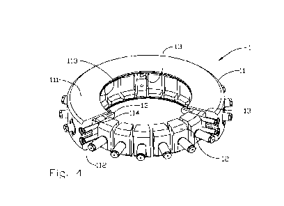
zo It is now referred to figure 2, 3, 4 and 5 wherein a clamp 1 is shown in
more de-
tails. The clamp 1 comprises a ring-shaped clamp body 11 with a through centre
opening 113. Between a first end portion 111 and a second end portion 112 of
the
clamp body 11 a groove 114 (see figure 3, 4 and 5) is provided inside the
clamp
body 11 co-axially with the centre opening 113, the groove 114 facing the
centre
opening 113.
The groove 114 holds several groups of clamping dogs 12, wherein adjacent
groups of clamping dogs 12 are separated by a parking dog 13. The number of
clamping dogs 12 may depend on the diameter of the flanges 21, 21a to be con-
nected. In a prototype of a clamp 1 configured for an element 2 with a
standard
135/8" centre opening, the clamp 1 is provided with a total number of eighteen
CA 03218308 2023- 11- 7
WO 2022/265513 7
PCT/N02022/050123
clamping dogs 12. In the prototype, the number of parking dogs 13 is three,
there-
by forming three groups of clamping dogs 12 as shown here for 135/8" element
centre opening. However, the number of clamping dogs 12 may be more than or
less than the eighteen shown, for example twelve, fifteen, twenty-one, when
three
parking dogs 13 are used as shown, and equal groups of clamping dogs 12 are
desired. To facilitate correct alignment between the flange 21 first entering
the
clamp 1 and the clamp 1 itself, at least three parking dogs 13 is preferred.
It is now referred to figures 6 and 7. The groove 114 is formed with a bottom
114a
and two opposing, parallel sidewalls 114b extending perpendicularly from the
bot-
tom 114a to the centre opening 113 of the clamp body 11.
Each clamping dog 12 is formed to supportingly grip over a portion of first
flange
periphery edges 211 (see fig. 1) of two adjacent flanges 21, 21a by end
portions of
a radially inwardly facing lateral side 121 being provided with two opposing
protru-
sions 123 forming first flange supporting flats 123a slanting from said
lateral side
121 towards an end portion 123b of each protrusion 123. End flats 122 of each
clamping dog 12 is configured for slidingly abutting against the groove
sidewalls
114b so that the clamping dogs 12 are supported by the groove sidewalls 114b.
A radially outwardly facing lateral side 124 of the clamping dog 12 is facing
the
groove bottom 114a and is provided with an actuator engaging portion 124a,
here
zo shown as a T-slot.
A first linear actuator 14 is provided for each clamping dog 12 and being
arranged
to radially displace the respective clamping dog 12 within the groove 114
between
a passive or retracted first position as shown in figures 3 and 4, and an
active or
extended position as shown in figures 2, 5, 6, and 8. Said first linear
actuator 14 is
in the embodiment shown a first screw engaging with internal threads 115a of a
first actuator bore 115 extending between the groove bottom 114a and the
periph-
ery of the clamp body 11. The first linear actuator 14 is engaging with the
actuator
engaging portion 124a of the clamping dog 12, here shown as a T-shaped end
portion 141 of the first screw 14 engaging with the T-slot 124a of the
clamping dog
12.
In fig. 3 are the parking dogs 13 and the clamping dogs 12 shown in the
retracted
CA 03218308 2023- 11- 7
WO 2022/265513 8
PCT/N02022/050123
or passive first position wherein the dogs 12, 13 fully accommodated within
the
clamp body 11. However, it should be noted that the dogs 12, 13 does not have
to
be fully accommodated within the clamp body 11 when being in the passive first
positions. It is sufficient that the dogs 12, 13 are retracted to an extent
that allows
passing of the flanges 21, 21a (see fig. 1).
Each parking dog 13 (see figure 7) is formed to supportingly rest on a portion
of
one of the two adjacent flanges 21, 21a to be connected by a first end portion
of a
radially inwardly facing lateral side 131 being provided with one protrusion
133
forming a second flange supporting flat 133a extending from the lateral side
131
towards an end portion133b of the protrusion 133. End flats 132 of each
parking
dog 13 is configured for slidingly abutting against the groove sidewalls 114b
so
that the parking dog 13 is supported by the groove sidewalls 114b.
In a preferred embodiment the second flange supporting flat 133a is slanting
from
said lateral side 131 towards the end portion 133b of the protrusion 133.
In a preferred embodiment a slanted end portion 134 is provided at the
radially
inwardly facing lateral side 131 opposite the protrusion 133.
A radially outwardly facing lateral side 135 of the parking dog 13 is facing
the
groove bottom 114a and is provided with an actuator engaging portion 135a,
here
shown as a T-slot.
A second linear actuator 15 is provided for each parking dog 13, arranged to
radi-
ally displace the respective parking dog 13 within the groove 114 between a
pas-
sive or retracted first position as shown in fig. 3, and an active or extended
position
as shown in figures 2, 5, 7, and 9. Said second linear actuator 15 is
preferably a
second screw engaging with internal threads 116a of a second actuator bore 116
extending between the groove bottom 114a of the groove 114, and to the periph-
ery of the clamp body 11. The second linear actuator 15 is engaging with the
actu-
ator engaging portion 135a of the parking dog 13, here shown as a T-shaped end
portion 151 of the second screw 15 engaging with the T-slot 135a of the
parking
dog 13.
A possible third linear actuator 16 is provided for each parking dog 13,
arranged to
CA 03218308 2023- 11- 7
WO 2022/265513 9
PCT/N02022/050123
support the respective parking dog 13 when in an extended, active position.
Said
third linear actuator 16 is preferably identical to the second actuator 15,
wherein a
third screw is engaging with internal threads 117a of a third actuator bore
117 ex-
tending between the groove bottom 114a to the periphery of the clamp body 11.
The third linear actuator 16 is engaging with the actuator engaging portion
135a of
the parking dog 13, here shown as a T-shaped end portion 161 of the third
screw
16 engaging with the T-slot 135a of the parking dog 13.
The second and third linear actuators 15, 16 are preferably arranged with end
stoppers 118 preventing the parking dogs 13 from being displaced too far into
the
centre opening 113 of the clamp 1. In the embodiment shown in figure 7 the end
stoppers 118 are extending from the sidewalls 114b of the groove 114 into
respec-
tive oblong recesses 136 in the end flats 132 of the parking dog 13.
In an alternative embodiment of the clamp body 11 shown in figures 8 and 9,
the
screws 14, 15, 16 forming the first linear actuator, the second linear
actuator and
the possible third linear actuator, respectively, are engaging with internal
threads
142b, 152b, 162b of a first sleeve142, a second sleeve 152 and a third sleeve
162,
respectively, wherein external threads 142a, 152a, 162a of the first sleeve
142, the
second sleeve 152 and the third sleeve 162, respectively, engaging with the
inter-
nal threads 115a, 116a, 117a, respectively, of the first actuator bore 115,
the sec-
ond actuator bore 116 and the third actuator bore 117, respectively. An effect
of
this embodiment is that said sleeves 142, 152, 162 are replaceable in case of
in-
ternal threads 142b, 152b, 162b, respectively, become damaged during the use
of
the clamp 1.
When an upright flanged first element 2 is to be clamped to an upright second
flanged element 2a by a clamp 1 according to the present invention (see fig.
1),
the clamp 1 with all clamping dogs 12 and parking dogs 13 being in the
retracted
position to allow passage of the flanges 21, 21a into the clamp 1, is placed
on a
convenient support (a floor, a table, or the like, not shown). The clamp 1 is
orient-
ed so that the protrusions 133 of the parking dogs 13 being closer to the
first
flange 21 than the support, i.e., the first end portion 111 of the clamp body
11 fac-
ing the flanged first element 2. The first element 2 is lowered onto the clamp
1 with
the lower, first flange 21 of the first element 2 entering the centre opening
113 of
CA 03218308 2023- 11- 7
WO 2022/265513 10
PCT/N02022/050123
the clamp body 11. The parking dogs 13 are then displaced radially inwards to
its
active position by operating the second linear actuators 15 so that the
parking
dogs 13 engage with the first flange 21 and thereby prevent separation between
the clamp 1 and the first flange 21. In the active position of the parking
dogs 13 the
second slanted flange supporting flats 133a of the protrusions 133 of the
parking
dogs 13 being arranged to lay supportingly on a first, upper flange periphery
211
of the first flange 21. If provided, the third linear actuators 16 may be used
as a
support for maintaining an upright position of the parking dogs 13 throughout
the
displacement of the parking dogs 13.
After having secured the clamp 1 with respect to the first element 2, the
first ele-
ment 2 is lifted carrying the clamp 1 connected to the lower, first flange 21
by the
parking dogs 13. By using three parking dogs 13, the three protrusions 133 are
forming a tripod providing a stable support of the clamp 1 with load evenly
distrib-
uted. Figure 1 shows this state of the clamping procedure.
The first element 2 is then lowered onto the second element 2a to which the
first
element 2 is to be connected. The lower portion of the centre opening 113
facing
the upper, second flange 21a of the second element 2a receives the second
flange 21a, the slanted end portions 134 of the parking dogs 13 facing an
upper,
second flange periphery edge 212 of the second flange 21, provide guidance of
the first element 2 with respect to the second element 2a and thus
facilitating the
insertion of the second flange 21a in the clamp 1. When the first and second
flanges 21, 21a mates, the clamping dogs 12 are displaced by operating the
first
linear actuators 14 to apply a clamping force onto the pair of flanges 21, 21a
by
the first slanted supporting flats 123a of the opposing protrusions 123
contacting
the remote first flange periphery edges 211 of the mating flanges 21, 21a.
A disconnection of the two elements 2, 2a is done by reversing the assembly
pro-
cedure described above.
It should be noted that the above-mentioned embodiments illustrate rather than
limit the invention, and that those skilled in the art will be able to design
many al-
ternative embodiments without departing from the scope of the appended claims.
In the claims, any reference signs placed between parentheses shall not be con-
CA 03218308 2023- 11- 7
WO 2022/265513 11
PCT/N02022/050123
strued as limiting the claim. Use of the verb "comprise" and its conjugations
does
not exclude the presence of elements or steps other than those stated in a
claim.
The article "a" or an preceding an element does not exclude the presence of a
plurality of such elements.
CA 03218308 2023- 11- 7