Note: Descriptions are shown in the official language in which they were submitted.
WO 2022/240493 PCT/US2022/022722
1
CONTAINER WITH PUSH-AND-SLIDE LOCKING MECHANISM
BACKGROUND
Field
[0001] Example embodiments generally relate to a container with a push-and-
slide
locking mechanism.
Description of Related Art
[0002] Packages can include locking, restraining, or retaining mechanisms that
reduce and/or prevent opening and subsequent exposure and/or ingestion of
substances contained therein by children or the elderly.
SUMMARY
[0003] At least one example embodiment relates to a container.
[0004] In at least one example embodiment, the container includes a base and a
lid.
The base includes a bottom wall and a peripheral wall. The peripheral wall is
perpendicular to the bottom wall. The peripheral wall and the bottom wall
define a
storage area. The peripheral wall at least partially defines a receptacle. The
lid is
configured to be moved between a closed and locked configuration and an open
configuration. The lid includes a top wall and a flexible tab. The flexible
tab projects
from the top wall. The flexible tab includes a fixed end adjacent to the top
wall and a
free end opposite the fixed end. The flexible tab is configured to move from a
relaxed
position to a flexed position in response to a force in a first direction and
return to the
relaxed position absent the force. In the closed and locked configuration, the
flexible tab
is in the relaxed position, at least partially in the receptacle, and
configured to engage
CA 03218899 2023- 11- 13
WO 2022/240493 PCT/US2022/022722
2
the base to retain the lid in the closed and locked configuration. The lid is
configured to
be moved from the closed and locked configuration to the open configuration by
moving
the lid in a second direction perpendicular to the first direction with the
flexible tab in
the flexed position.
[0005] In at least one example embodiment, the base further includes a
receptacle
wall. The receptacle wall cooperates with the peripheral wall to at least
partially define
the receptacle.
[0006] In at least one example embodiment, the receptacle wall is spaced from
the
peripheral wall in the first direction.
[0007] In at least one example embodiment, the receptacle wall is centered
along a
transverse axis perpendicular to the first direction and the second direction.
[0008] In at least one example embodiment, the peripheral wall defines a
recess in
communication with the receptacle.
[0009] In at least one example embodiment, the flexible tab includes a
projection
configured to be at least partially in the recess in the closed and locked
configuration.
[0010] In at least one example embodiment, the projection is recessed with
respect to
the peripheral wall in the closed and locked configuration.
[0011] In at least one example embodiment, the projection is configured to
engage the
peripheral wall to retain the container in the closed and locked
configuration.
[0012] In at least one example embodiment, the projection extends between a
proximal end and a distal end. The proximal end includes a proximal end
surface
configured to engage the peripheral wall to retain the lid in the closed and
locked
configuration.
[0013] In at least one example embodiment, the projection includes a plurality
of
parallel ribs.
CA 03218899 2023- 11- 13
WO 2022/240493 PCT/US2022/022722
3
10014] In at least one example embodiment, the plurality of parallel ribs
includes a
respective plurality of distal ends defining a curved profile.
[0015] In at least one example embodiment, the curved profile is convex with
respect
to the free end of the flexible tab.
[0016] In at least one example embodiment, the each of the plurality of
parallel ribs
is tapered along at least a portion of a rib length.
10017] In at least one example embodiment, the free end of the flexible tab is
configured to be aligned or recessed with respect to the bottom wall in the
closed and
locked configuration.
[0018] In at least one example embodiment, the flexible tab is configured to
pivot
through an angle ranging from 40 to 8 between the relaxed position and the
flexed
position.
[0019] In at least one example embodiment, the fixed end of the flexible tab
defines a
thickness ranging from 1 mm to 1.5 mm parallel to the first direction.
[0020] In at least one example embodiment, the free end of the flexible tab is
tapered
along at least a portion of a length of the flexible tab.
[0021] In at least one example embodiment, the fixed end of the flexible tab
defines a
first width perpendicular to the first direction and the second direction. The
free end of
the flexible tab defines a second width perpendicular to the first direction
and the second
direction. The second width is less than the first width.
[0022] In at least one example embodiment, the lid is pivotally coupled to the
base.
[0023] In at least one example embodiment, the container further includes a
living
hinge coupling the lid to the base.
10024] In at least one example embodiment, the container defines a rectangular
profile.
CA 03218899 2023- 11- 13
WO 2022/240493 PCT/US2022/022722
4
10025] In at least one example embodiment, the peripheral wall includes a pair
of
opposing side walls and a pair of opposing end walls. The pair of opposing
side walls
define a first length. The pair of opposing end walls has a second length less
than the
first length.
10026] In at least one example embodiment, one of the pair of opposing end
walls at
least partially defines the receptacle.
[0027] In at least one example embodiment, the base and the lid include
polypropylene.
10028] In at least one example embodiment, the base and the lid further
include talc.
[0029] In at least one example embodiment, the base and the lid further
include a
colorant.
BRIEF DESCRIPTION OF THE DRAWINGS
10030] The various features and advantages of the non-limiting embodiments
herein
may become more apparent upon review of the detailed description in
conjunction with
the accompanying drawings. The accompanying drawings are merely provided for
illustrative purposes and should not be interpreted to limit the scope of the
claims. The
accompanying drawings are not to be considered as drawn to scale unless
explicitly
noted. For purposes of clarity, various dimensions of the drawings may have
been
exaggerated.
[0031] FIG. 1 is an illustration of a perspective view of a package, in
accordance with
at least one example embodiment;
10032] FIG. 2 is an illustration of the package in an opened configuration, in
accordance with at least one example embodiment;
[0033] FIG. 3 is an illustration of another perspective view of the package in
the
CA 03218899 2023- 11- 13
WO 2022/240493 PCT/US2022/022722
opened configuration, in accordance with at least one example embodiment;
[0034] FIG. 4 is an illustration of a close-up view of a portion of a locking
mechanism
of the package, in accordance with at least one example embodiment;
[0035] FIG. 5 is an illustration of a close-up view of an arm of the package,
in
accordance with at least one example embodiment;
[0036] FIG. 6 is an illustration of an upper view of the package in the opened
configuration, in accordance with at least one example embodiment;
[0037] FIG. 7 is an illustration of a lower view of the package in the opened
configuration, in accordance with at least one example embodiment;
[0038] FIG. 8 is an illustration of a side view of the package in the opened
configuration, in accordance with at least one example embodiment;
[0039] FIG. 9 is an illustration of a perspective view of the package, in
accordance
with at least one example embodiment;
[0040] FIG. 10 is an illustration of a perspective view of a secondary storage
area of
the package, in accordance with at least one example embodiment;
[0041] FIG. 11 is an illustration of an exploded view of the package, in
accordance
with at least one example embodiment;
[0042] FIG. 12 is an illustration of a perspective view of a frame and lid of
the package,
in accordance with at least one example embodiment;
[0043] FIG. 13 is an illustration of a perspective view of an insert of the
package, in
accordance with at least one example embodiment;
[0044] FIG. 14 is an illustration of a perspective view of another package, in
a partially
opened configuration, in accordance with at least one example embodiment;
[0045] FIG. 15 is an illustration of a cross-sectional view of the package, in
accordance with at least one example embodiment;
CA 03218899 2023- 11- 13
WO 2022/240493 PCT/US2022/022722
6
10046] FIG. 16A is an illustration of a perspective view of another package in
an
opened configuration, in accordance with at least one example embodiment;
[0047] FIG. 16B is an enlarged view of the arm of the locking mechanism of
FIG. 16A
according to at least one example embodiment; and
[0048] FIG. 17 is an illustration of a perspective view of the package of FIG.
16 in a
closed configuration, in accordance with at least one example embodiment;
10049] FIG. 18 is an illustration of a perspective view of a package, in
accordance with
at least one example embodiment;
[0050] FIG. 19 is an illustration of a perspective view of the package in a
partially
opened configuration, in accordance with at least one example embodiment;
10051.] FIG. 20 is an illustration of another perspective view of the package
in the
partially opened configuration, in accordance with at least one example
embodiment;
[0052] FIG. 21 is an illustration of a cross-sectional view of the package in
the
partially opened configuration, in accordance with at least one example
embodiment;
[0053] FIG. 22 is an illustration of a close-up view of locking mechanisms of
the
package, in accordance with at least one example embodiment;
[0054] FIG. 23 is an illustration of a close-up view of locking mechanisms of
the
package, in accordance with at least one example embodiment;
[0055] FIG. 24 is an illustration of a side view of the package, in accordance
with at
least one example embodiment;
10056] FIG. 25 is an illustration of a lower perspective view of the package,
in
accordance with at least one example embodiment;
[0057] FIG. 26 is an illustration of another lower perspective view of the
package, in
accordance with at least one example embodiment;
[0058] FIG. 27 is an illustration of a perspective view of the package with
the lid
CA 03218899 2023- 11- 13
WO 2022/240493 PCT/US2022/022722
7
detached, in accordance with at least one example embodiment;
[0059] FIG. 28 is an illustration of the lid of the package, in accordance
with at least
one example embodiment;
[0060] FIG. 29 is an illustration of an upper perspective view of the base of
the
package, in accordance with at least one example embodiment;
[0061] FIG. 30 is an illustration of a lower perspective view of the base of
the package,
in accordance with at least one example embodiment;
[0062] FIG. 31A is an illustration of a vertical cross-sectional view of the
flexible
structure, in accordance with at least one example embodiment;
[0063] FIG. 31B is an illustration of a vertical cross-sectional view of the
flexible
structure, in accordance with at least one example embodiment;
[0064] FIG. 31C is an illustration of an overhead view of another flexible
structure, in
accordance with at least one example embodiment;
[0065] FIG. 31D is an illustration of a vertical cross-sectional view of the
flexible
structure, in accordance with at least one example embodiment;
[0066] FIG. 32 is an illustration of a perspective view of another package, in
accordance with at least one example embodiment;
[0067] FIG. 33 is an illustration of the package of FIG. 32 in an opened
configuration,
in accordance with at least one example embodiment;
[0068] FIG. 34A is an illustration of a close-up view of a portion of a
locking
mechanism, in accordance with at least one example embodiment; and
[0069] FIG. 34B is an illustration of another close-up of a locking mechanism,
in
accordance with at least one example embodiment.
[0070] FIGS. 35A and 35B are illustrations of perspective views of another
package
in a closed configuration, in accordance with at least one example embodiment;
CA 03218899 2023- 11- 13
WO 2022/240493 PCT/US2022/022722
8
10071] FIGS. 36A and 36B are illustrations of perspective views of the package
in an
open configuration, in accordance with at least one example embodiment;
[0072] FIGS. 37A, 37B, and 37C are illustrations of close-up perspective cross-
sectional views of a portion of the package along cross-sectional view line
)(XXVII-
XXXVIF of FIG. 35A, in accordance with at least one example embodiment;
[0073] FIGS. 37D and 37E are illustrations of perspective cross-sectional
views of the
package along cross-sectional view line XXXVIID-X./XXVIID' of FIG. 35A, in
accordance
with at least one example embodiment;
[0074] FIG. 37F is an illustration of a perspective cross-sectional view of
the package
along cross-sectional view line XXXVIIF-XXXVIIF' of FIG. 36A, in accordance
with at
least one example embodiment;
10075] FIGS. 38A, 383, and 380 are illustrations of close-up perspective cross-
sectional views of a portion of the package along cross-sectional view line
XXXVIII-
XXXVIII' of FIG. 35A, in accordance with at least one example embodiment;
[0076] FIG. 39A is an illustration of a close-up perspective cross-sectional
view of a
portion of the package along cross-sectional view line XXXIXA-XXXIXA' of FIG.
35A, in
accordance with at least one example embodiment;
[0077] FIG. 39B is an illustration of a close-up perspective cross-sectional
view of a
portion of the package along cross-sectional view line XXXIXB-XXXIXB' of FIG.
36A, in
accordance with at least one example embodiment;
[0078] FIG. 40 is an illustration of an exploded view of the package in the
open
configuration, in accordance with at least one example embodiment;
[0079] FIGS. 41A and 41B are illustrations of perspective views of a frame and
lid of
the package, in accordance with at least one example embodiment;
[0080] FIG. 42 is an illustration of a close-up perspective cross-sectional
view of a
CA 03218899 2023- 11- 13
WO 2022/240493 PCT/US2022/022722
9
portion of a frame along cross-sectional view line XLII-XLIF of FIG. 41B, in
accordance
with at least one example embodiment;
[0081] FIGS. 43A and 43B are illustrations of perspective views of an insert
of the
package, in accordance with at least one example embodiment;
10082] FIG. 44A is an illustration of a perspective view of the package with
the
secondary lid in an open position in accordance with at least one example
embodiment;
[0083] FIG. 44B is an illustration of a perspective cross-sectional view of
the package
along cross-sectional view line XLIVB-XLIVB' of FIG. 44A, in accordance with
at least
one example embodiment;
[0084] FIG. 45 is an illustration of a close-up perspective cross-sectional
view of a
portion of the package along cross-sectional view line XLV-XLV' of FIG. 44A,
in
accordance with at least one example embodiment;
[0085] FIG. 46 is an illustration of a side cross-sectional view of a portion
of the
package along cross-sectional view line XLVI-XLVI' of FIG. 44A, in accordance
with at
least one example embodiment;
[0086] FIG. 47 is an illustration of a side cross-sectional view of a portion
of the
package along cross-sectional view line XLVII-XLVII' of FIG. 35B, in
accordance with at
least one example embodiment;
[0087] FIG. 48 is a top front perspective view of a container in a closed and
locked
configuration in accordance with at least one example embodiment;
[0088] FIG. 49 is a top front perspective view of the container of FIG. 48 in
an open
configuration in accordance with at least one example embodiment;
[0089] FIG. 50 is a top back perspective view of the container of FIG. 48 in
the open
configuration in accordance with at least one example embodiment;
10090] FIG. 51 is a partial top front perspective view of a base of the
container of
CA 03218899 2023- 11- 13
WO 2022/240493 PCT/US2022/022722
FIG. 48 including a receptacle in accordance with at least one example
embodiment;
[0091] FIG. 52 is a partial top view of the base of FIG. 51 including the
receptacle in
accordance with at least one example embodiment;
[0092] FIG. 53 is a front view of the container of FIG. 48 in the open
configuration in
accordance with at least one example embodiment;
[0093] FIG. 54 is a partial front perspective view of a lid of the container
of FIG. 48
including a flexible tab in accordance with at least one example embodiment;
[0094] FIG. 55 is a partial front view of the lid of FIG. 54 including the
flexible tab in
accordance with at least one example embodiment;
[0095] FIG. 56 is a partial sectional view of the flexible tab of FIG. 55
taken at line 56-
56 of FIG. 55 according to at least one example embodiment;
[0096] FIG. 57 is a front view of the container of FIG. 48 in accordance with
at least
one example embodiment;
[0097] FIG. 58 is a partial sectional view of the container of FIG. 57 taken
in at
line 58-58 of FIG. 57 in accordance with at least one example embodiment;
10098] FIG. 59 is a front perspective view of the container of FIG. 48 in a
partially
open configuration in accordance with at least one example embodiment;
[0099] FIG. 60 is a bottom back perspective view of the container of FIG. 48
with a
secondary lid in a closed position in accordance with at least one example
embodiment;
[00100] FIG. 61 is a bottom back perspective view of the container of FIG. 60
with the
secondary lid in an open position in accordance with at least one example
embodiment;
[00101] FIG. 62 is a top front exploded perspective view of the container of
FIG. 48 in
accordance with at least one example embodiment;
[00102] FIG. 63 is a partial perspective view of a frame of the container of
FIG. 62
including a wedge in accordance with at least one example embodiment;
CA 03218899 2023- 11- 13
WO 2022/240493 PCT/US2022/022722
11
100103] FIG. 64 is a sectional view of the frame of FIG. 62 including the
wedge taken
at line 63-63 of FIG. 62 in accordance with at least one example embodiment;
100104] FIG. 65 is a top back perspective view of the frame of the container
of FIG. 62
in the open configuration in accordance with at least one example embodiment;
[00105] FIG. 66 is a partial side view of the frame of FIG. 65 including a
stop in
accordance with at least one example embodiment;
100106] FIG. 67 is a front bottom perspective view of the frame of FIG. 65 in
accordance
with at least one example embodiment;
100107] FIG. 68 is a top back perspective view of an insert of the package of
FIG. 62 in
accordance with at least one example embodiment;
100108] FIG. 69 is a partial sectional view of the insert of FIG. 68 taken at
line 69-69
of FIG. 68 in accordance with at least one example embodiment;
100109] FIG. 70 is a partial sectional view of the container of FIG. 48 taken
at line 70-
70 of FIG. 48 in accordance with at least one example embodiment;
[00110] FIG. 71 is a partial sectional view of the container of FIG. 48 taken
at line 71-
71 of FIG. 48 in accordance with at least one example embodiment;
100111] FIG. 72 is a top front perspective view of a container (or package) in
a closed
and locked configuration in accordance with at least one example embodiment;
[00112] FIG. 73 is a top front perspective view of the container of FIG. 72 in
an open
configuration in accordance with at least one example embodiment;
100113] FIG. 74 is a top back perspective view of the container of FIG. 72 in
the open
configuration in accordance with at least one example embodiment;
[00114] FIG. 75 is a sectional view of a base of the container of FIG. 72
taken along
line 75-75 of FIG. 74 in accordance with at least one example embodiment;
100115] FIG. 76 is another sectional view the base of FIG. 75 taken along line
76-76 of
CA 03218899 2023- 11- 13
WO 2022/240493 PCT/US2022/022722
12
FIG. 74 in accordance with at least one example embodiment;
[00116] FIG. 77 is a detail sectional view of a protrusion of the base of FIG.
76 in
accordance with at least one example embodiment;
[00117] FIG. 78 is a partial perspective view of the protrusion of FIG. 77 in
accordance
with at least one example embodiment;
[00118] FIG. 79 is a perspective view of an inside of a lid of the container
of FIG. 72 in
accordance with at least one example embodiment;
[00119] FIG. 80 is a partial side view of a skirt of the lid of FIG. 79
including a
receptacle in accordance with at least one example embodiment;
[00120] FIG. 81 is a top view of the base of FIG. 75 in accordance with at
least one
example embodiment;
100121] FIG. 82 is a side view of thc containcr of FIG. 72 in thc closed and
locked
configuration according to at least one example embodiment;
100122] FIG. 83 is a partial sectional view of the container of FIG. 82 taken
along line
83-83 of FIG. 82;
[00123] FIG. 84 is an end view of the container of FIG. 72 in the closed and
locked
configuration according to at least one example embodiment;
[00124] FIG. 85 is a partial sectional view of the container of FIG. 84 taken
along line
85-85 of FIG. 84;
[00125] FIG. 86 is a bottom back perspective view of the package of FIG. 72
with a
secondary lid in a closed position in accordance with at least one example
embodiment;
[00126] FIG. 87 is a bottom back perspective view of the package of FIG. 86
with the
secondary lid in an open position in accordance with at least one example
embodiment;
[00127] FIG. 88 is a top perspective view of a package in a closed and locked
configuration in accordance with at least one example embodiment;
CA 03218899 2023- 11- 13
WO 2022/240493 PCT/US2022/022722
13
100128] FIG. 89 is a first side perspective view of the package of FIG. 88 in
an open
configuration in accordance with at least one example embodiment;
[00129] FIG. 90 is a second side perspective view of the package of FIG. 88 in
an open
configuration in accordance with at least one example embodiment;
[00130] FIG. 91 is bottom perspective view of the package of FIG. 88 in an
open
configuration in accordance with at least one example embodiment;
100131] FIG. 92 is a side, bottom perspective view of the package of FIG. 88
in an open
configuration in accordance with at least one example embodiment;
100132] FIG. 93 is a top perspective view of a base of the package of FIG. 88
in
accordance with at least one example embodiment;
100133] FIG. 94 is a cross-sectional view of the base of FIG. 93 in accordance
with at
least one example embodiment;
100134] FIG. 95 is a bottom perspective view of a lid of the package of FIG.
88 in
accordance with at least one example embodiment;
[00135] FIG. 96 is a cross-sectional view of the lid of FIG. 95 in accordance
with at
least one example embodiment; and
1001.36] FIG. 97 is a cross-sectional view of the package of FIG. 88 in an
open
configuration in accordance with at least one example embodiment.
DETAILED DESCRIPTION
[00137] Some detailed example embodiments are disclosed herein. However,
specific
structural and functional details disclosed herein are merely representative
for purposes
of describing example embodiments. Example embodiments may, however, be
embodied
in many alternate forms and should not be construed as limited to only the
example
embodiments set forth herein.
CA 03218899 2023- 11- 13
WO 2022/240493 PCT/US2022/022722
14
100138] Accordingly, while example embodiments are capable of various
modifications
and alternative forms, example embodiments thereof are shown by way of example
in
the drawings and will herein be described in detail. It should be understood,
however,
that there is no intent to limit example embodiments to the particular forms
disclosed,
but to the contrary, example embodiments are to cover all modifications,
equivalents,
and alternatives thereof. Like numbers refer to like elements throughout the
description
of the figures.
1001.39] It should be understood that when an element or layer is referred to
as being
"on," "connected to," "coupled to," or "covering" another element or layer, it
may be
directly on, connected to, coupled to, or covering the other element or layer
or
intervening elements or layers may be present. In contrast, when an element is
referred
to as being "directly on," "directly connected to," or "directly coupled to"
another element
or layer, there are no intervening elements or layers present. Like numbers
refer to like
elements throughout the specification. As used herein, the term "and/or"
includes any
and all combinations or sub-combinations of one or more of the associated
listed items.
1001.40] It should be understood that, although the terms first, second,
third, etc. may
be used herein to describe various elements, regions, layers and/or sections,
these
elements, regions, layers, and/or sections should not be limited by these
terms. These
terms are only used to distinguish one element, region, layer, or section from
another
region, layer, or section. Thus, a first element, region, layer, or section
discussed below
could be termed a second element, region, layer, or section without departing
from the
teachings of example embodiments.
10031.431.] Spatially relative terms (e.g., "beneath," "below," "lower,"
"above," "upper," and
the like) may be used herein for ease of description to describe one element
or feature's
relationship to another element(s) or feature(s) as illustrated in the
figures. It should be
CA 03218899 2023- 11- 13
WO 2022/240493 PCT/US2022/022722
understood that the spatially relative terms are intended to encompass
different
orientations of the device in use or operation in addition to the orientation
depicted in
the figures. For example, if the device in the figures is turned over,
elements described
as "below" or "beneath" other elements or features would then be oriented
"above" the
other elements or features. Thus, the term "below" may encompass both an
orientation
of above and below. The device may be otherwise oriented (rotated 90 degrees
or at other
orientations) and the spatially relative descriptors used herein interpreted
accordingly.
[00142] The terminology used herein is for the purpose of describing various
example
embodiments only and is not intended to be limiting of example embodiments. As
used
herein, the singular forms "a," "an," and "the" are intended to include the
plural forms
as well, unless the context clearly indicates otherwise. It will be further
understood that
the terms "includes," "including," "comprises," and/or "comprising," when used
in this
specification, specify the presence of stated features, integers, steps,
operations, and/or
elements, but do not preclude the presence or addition of one or more other
features,
integers, steps, operations, elements, and/or groups thereof.
[00143] When the words "about" and "substantially" are used in this
specification in
connection with a numerical value, it is intended that the associated
numerical value
include a tolerance of - 10% around the stated numerical value, unless
otherwise
explicitly defined.
[00144] Unless otherwise defined, all terms (including technical and
scientific terms)
used herein have the same meaning as commonly understood by one of ordinary
skill
in the art to which example embodiments belong. It will be further understood
that
terms, including those defined in commonly used dictionaries, should be
interpreted as
having a meaning that is consistent with their meaning in the context of the
relevant
CA 03218899 2023- 11- 13
WO 2022/240493 PCT/US2022/022722
16
art and will not be interpreted in an idealized or overly formal sense unless
expressly so
defined herein.
[00145] Example embodiments are described herein with reference to cross-
sectional
illustrations that are schematic illustrations of idealized embodiments (and
intermediate
structures) of example embodiments. As such, variations from the shapes of the
illustrations as a result, for example, of manufacturing techniques and/or
tolerances,
are to be expected. Thus, example embodiments should not be construed as
limited to
the shapes of regions illustrated herein but are to include deviations in
shapes that
result, for example, from manufacturing.
PACKAGE
[00146] At least some example embodiments are directed to packages and/or
containers that are considered to be "child-resistant packages (CR packages),"
from the
standpoint that an opening of the packages requires a complex motion involving
an
application of different forces in different directions. In at least one
example
embodiment, CR packages are used to reduce a risk of children and/ or the
elderly
accessing and ingesting, or being exposed to, substances or materials
contained therein.
In at least some example embodiment, the packages are tested under guidelines
from
the Consumer Product Safety Commission (CPSC) Poison Prevention Packaging Act
and
are certified under 16 CFR 1700.2 (January 1, 2012), and/or the packages are
tested
as defined by Standard ISO 8317:2015, in order to ensure the packages are
"child-
resistant" and provide child-resistant access to one or more storage areas of
the
packages. In at least one example embodiment, the packages are tested under
guidelines
from Canadian standard CAN/ CSA Z76.1-16.
CA 03218899 2023- 11- 13
WO 2022/240493
PCT/US2022/022722
17
100147] In at least one example embodiment, the packages include or can
contain at
least one substance. In at least one example embodiment, the at least one
substance is
a consumer product. In at least one example embodiment, the at least one
substance
and/or the consumer product includes an oral product. In at least one example
embodiment, the oral product is one or more pouches.
[00148] In at least one example embodiment, the oral product is an oral
tobacco
product, an oral non-tobacco product, an oral cannabis product, or any
combination
thereof. The oral product may be in a form of loose material (e.g., loose
cellulosic
material), shaped material (e.g., plugs or twists), pouched material, tablets,
lozenges,
chews, gums, films, any other oral product, or any combination thereof.
100149] The oral product may include chewing tobacco, snus, moist snuff
tobacco, dry
snuff tobacco, other smokeless tobacco and non-tobacco products for oral
consumption,
or any combination thereof.
[00150] Where the oral product is an oral tobacco product including smokeless
tobacco
product, the smokeless tobacco product may include tobacco that is whole,
shredded,
cut, granulated, reconstituted, cured, aged, fermented, pasteurized, or
otherwise
processed. Tobacco may be present as whole or portions of leaves, flowers,
roots, stems,
extracts (e.g., nicotine), or any combination thereof.
100151] In at least one example embodiment, the oral product includes a
tobacco
extract, such as a tobacco-derived nicotine extract, and/or synthetic
nicotine. The oral
product may include nicotine alone or in combination with a carrier (e.g.,
white snus),
such as a cellulosic material. The carrier may be a non-tobacco material
(e.g.,
microcrystalline cellulose) or a tobacco material (e.g., tobacco fibers having
reduced or
eliminated nicotine content, which may be referred to as "exhausted tobacco
plant tissue
or fibers"). In some example embodiments, the exhausted tobacco plant tissue
or fibers
CA 03218899 2023- 11- 13
WO 2022/240493 PCT/US2022/022722
18
can be treated to remove at least 25%, 40%, 50%, 60%, 70%, 75%, 80%, 85%, 90%,
or
95% of the nicotine. For example, the tobacco plant tissue can be washed with
water or
another solvent to remove the nicotine.
[00152] In other example embodiments, the oral product may include cannabis,
such
as cannabis plant tissue and/or cannabis extracts. In at least one example
embodiment,
the cannabis material includes leaf and/or flower material from one or more
species of
cannabis plants and/or extracts from the one or more species of cannabis
plants. The
one or more species of cannabis plants may include Cannabis sativa, Cannabis
indica,
and/or Cannabis ruderalis. In at least one example embodiment, the cannabis
may be
in the form of fibers. In at least one example embodiment, the cannabis may
include a
cannabinoid, a terpene, and/or a flavonoid. In at least one example
embodiment, the
cannabis material may be a cannabis-derived cannabis material, such as a
cannabis-
derived cannabinoid, a cannabis-derived terpene, and/or a cannabis-derived
flavonoid.
[00153] The oral product (e.g., the oral tobacco product, the oral non-tobacco
product,
or the oral cannabis product) may have various ranges of moisture. In at least
one
example embodiment, the oral product is a dry oral product having a moisture
content
ranging from 5% by weight to 10% by weight. In at least one example
embodiment, the
oral product has a medium moisture content, such as a moisture content ranging
from
20% by weight to 35% by weight. In at least one example embodiment, the oral
product
is a wet oral product having a moisture content ranging from 40% by weight to
55% by
weight.
[00154] In at least one example embodiment, oral product may further include
one or
more elements such as a mouth-stable polymer, a mouth-soluble polymer, a
sweetener
(e.g., a synthetic sweetener and/or a natural sweetener), an energizing agent,
a soothing
agent, a focusing agent, a plasticizer, mouth-soluble fibers, an alkaloid, a
mineral, a
CA 03218899 2023- 11- 13
WO 2022/240493 PCT/US2022/022722
19
vitamin, a dietary supplement, a nutraceutical, a coloring agent, an amino
acid, a
chemesthetic agent, an antioxidant, a food-grade emulsifier, a pH modifier, a
botanical,
a tooth-whitening agent, a therapeutic agent, a processing aid, a stearate, a
wax, a
stabilizer, a disintegrating agent, a lubricant, a preservative, a filler, a
fiavorant, flavor
masking agents, a bitterness receptor site blocker, a receptor site enhancers,
other
additives, or any combination thereof.
1001.55] In at least one example embodiment, the package may contain any
product or
substance. For example, the package may contain confectionary products, food
products, medicines, or any other product.
FIRST EXAMPLE EMBODIMENT
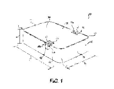
[00156] FIG. 1 is a perspective view of a package 100, in accordance with at
least one
example embodiment.
100157] In at least one example embodiment, as shown in FIG. 1, the package
100 is
substantially rectangular in shape, from an overhead perspective (see at least
FIG. 6).
In at least one example embodiment, the package 100 may have any other
suitable
shape. In at least one example embodiment, from an overhead perspective view,
the
package 100 is triangular, oval, square, circular, polygonal, or any other
shape.
100158] In at least one example embodiment, the package 100 includes a base
130. In
at least one example embodiment, the base 130 includes sidewalls 132 along a
long side
of the base 130, and end walls 135 along a short side of the base 130. In at
least one
example embodiment, the walls (e.g., sidewalls 132 and end walls 135) of the
package
100 are a same length. In at least one example embodiment, the base 130
includes
curved (beveled) corners 138 connecting the sidewalls 132 to the end walls
135. In other
example embodiments, the corners 138 may not be rounded or beveled, but may
instead
CA 03218899 2023- 11- 13
WO 2022/240493 PCT/US2022/022722
have sharp outer edges.
100159] In at least one example embodiment, the package 100 includes a primary
lid
120 that meets with an upper portion of the base 130 to close the package 100.
In at
least one example embodiment, the base 130 may be connected to the primary lid
120
via a hinge 11-0. In at least one example embodiment, the hinge 140 is a
living hinge (as
further discussed with respect to FIGS. 2-3). In other example embodiments,
the
primary lid 120 may be completely removable from the base 130, and may not be
hingedly connected to the base 130. In at least one example embodiment, the
primary
lid 120 includes an exterior surface 124 that is visible when the package 100
is in a
closed configured, as shown in FIG. 1.
100160] In at least one example embodiment, the base 130 has a height H
ranging from
about 0.5 inch to 2.0 inches (e.g., about 0.75 inch to about 1.75 inches,
about 1.0 inch
to about 1.5 inches). In at least one example embodiment, each of the
sidewalls 132 has
a length Li ranging from about 2.0 inches to about 6.0 inches (e.g., about 2.5
inches to
about 5.5 inches, about 3.0 inches to about 5.0 inches, or about 3.5 inches to
about
4.5 inches). In at least one example embodiment, each of the end walls 135 has
a length
L2 ranging from about 1.0 inch to about 4.0 inches (e.g., about 1.5 inches to
about 3.5
inches, about 2.0 inches to about 3.0 inches, or about 2.25 inches to about
2.75 inches).
It should be understood that the package 100 may be any suitable size, and the
dimensions can be chosen based on the product to be contained therein.
100161] In at least one example embodiment, the sidewalls 132 and/or the end
walls
135 have a thickness T ranging from about 0.1 mm to about 2.0 mm (e.g., about
0.5
mm to about 1.5 mm or about 0.7 mm to about 0.9 mm).
100162] In at least one example embodiment, the package 100 is formed from one
or
more polymers. In at least one example embodiment, the package 100 is formed
of one
CA 03218899 2023- 11- 13
WO 2022/240493 PCT/US2022/022722
21
or more homopolymers, one or more copolymers, or any combination of one or
more
homopolymers and copolymers. In at least some example embodiments, the polymer
includes a thermoplastic polymer. In at least some example embodiments, the
polymer
includes polyethylene terephthalate (PET), polypropylene (PP), a polyethylene
(PE), or
any combination thereof. In at least one example embodiment, the polymer is
suitable
for storing an oral product having one or more flavorings and/or volatile
agents therein.
In some example embodiments, the package 100 may further include one or more
coatings on an inner surface thereof, if desired.
100163] In at least one example embodiment, the package 100 is formed from a
polymer, as described above, and a filler, such as talc. The filler may be
present in an
amount less than or equal to about 50 weight percent (e.g., less than or equal
to about
45 weight percent, less than or equal to about 40 weight percent, less than or
equal to
about 30 weight percent, less than or equal to about 25 weight percent, less
than or
equal to about 20 weight percent, less than or equal to about 15 weight
percent, less
than or equal to about 10 weight percent, or less than or equal to about 5
weight
percent). Thc filler may bc present in an amount greater than or equal to 0
weight
percent (e.g., greater than or equal to about 5 weight percent, greater than
or equal to
about 10 weight percent, greater than or equal to about 15 weight percent,
greater than
or equal to about 20 weight percent, greater than or equal to about 25 weight
percent,
greater than or equal to about 30 weight percent, greater than or equal to
about 35
weight percent, greater than or equal to about 40 weight percent, or greater
than or
equal to about 4-5 weight percent). In at least one example embodiment, the
package
100 further includes a colorant (with or without a filler),In at least one
example
embodiment, the base 130 and the primary lid 120 are formed of the same
polymer. In
other example embodiments, the base 130 is formed of a different polymer than
the
CA 03218899 2023- 11- 13
WO 2022/240493 PCT/US2022/022722
22
primary lid 120.
100164] In at least one example embodiment, the base 130 and/or the primary
lid 120
may be a same or a different color. In at least one example embodiment, a
color of the
package 100 may denote a flavor of the enclosed product. For example, a green
container
may contain a mint or menthol flavored product, while a brown container may
contain
a tobacco flavored product.
100165] In at least one example embodiment, the package 100 is formed by
injection
molding, blow molding, thermoforming, compression molding, vacuum casting, 3D
printing and/or any other any other suitable process.
100166] In at least one example embodiment, the package 100 includes at least
one
locking, restraining or retaining mechanism 150. While the use of the term
locking
mechanism will be used throughout the example embodiments. It will he
understood
that the locking mechanism operates to restrain movement of, for example, a
lid of the
package from a closed position or configuration to an open position or
configuration;
and may not necessarily prevent opening. As such, the packages described
herein
provide a measure of child resistant opening, but do not provide child proof
opening. In
at least one example embodiment, as shown in FIG. 1, the at least one locking
mechanism 150 includes a first locking mechanism 150a and a second locking
mechanism 150b. In at least one example embodiment, the locking mechanisms 150
oppose each other on the package 100. In at least one example embodiment, the
package
100 includes one locking mechanism 150. In other example embodiments, the
package
100 includes more than two locking mechanisms 150 (e.g., 3, 4, 5, 6, 7, 8, 9,
or 10).
100167] In at least one example embodiment, the locking mechanisms 150 are
positioned along the sidewalls 132 of the package 100. In other example
embodiments,
the locking mechanisms 150 can be positioned along one or both of the end
walls 135
CA 03218899 2023- 11- 13
WO 2022/240493
PCT/US2022/022722
23
and/or positioned along one sidewall 132. In at least one example embodiment,
the
locking mechanisms 150 can be centrally positioned or non-centrally positioned
along
the sidewalls 132 and/or the end walls 135. In at least one example
embodiment, the
locking mechanisms 150 are positioned between about 20 mm and about 35 mm from
a first one of the end walls 135 (the end wall 135 that is opposite a position
of the hinge
140), or about 27.2 mm from the first one of the end walls 135. Positioning of
the locking
mechanisms 150 may be chosen to further inhibit the relatively small hands of
a child
from being able to grasp and/or open the package 100. In one embodiment, the
locking
mechanisms 150 may be placed symmetrically about a longitudinal axis of the
package
100. In another embodiment, the locking mechanisms may be placed
asymmetrically
about a longitudinal axis of the package 100.
[00168] FIG. 2 is an illustration of the package 100 of FIG. 1 in an opened
configuration
(opened position), in accordance with at least one example embodiment.
[00169] In at least one example embodiment, as shown in FIGS. 1 and 2, each
locking
mechanism 150 includes an arm 160 (described in more detail with respect to
FIG. 2)
and a tab (contact structure, or contact plate) 152 at an end of each arm 160.
In at least
one example embodiment, the tab 152 includes an upper surface 152a that is
substantially flush with the exterior surface 4 of the primary lid 120. In at
least one
example embodiment, the tab 152 is positioned near an upper portion of the
sidewall
132 of the package 100. In at least one embodiment, the tab 152 is positioned
near an
upper portion of the end wall 135 of the package 100. The tab also has an
outer surface
152b, which is flush with an exterior surface of the sidewall 132. The tab 152
provides
a contact surface, against which an adult consumer may push when opening the
package 100 as further described herein.
[00170] In at least one example embodiment, an upper surface 136 of the base
130 is
CA 03218899 2023- 11- 13
WO 2022/240493
PCT/US2022/022722
24
about flush with the exterior surface 124 of the primary lid 120 so as to
mitigate pick
points and the ability to circumvent the locking mechanisms 150 when the
primary lid
120 is in a closed position (closed configuration, as shown in FIG. 1). As
shown in FIG. 1,
the primary lid 120 nests within the base 130 when closed. However, in other
example
embodiments, the primary lid 120 may overlap an upper edge of the base 130
when
closed.
[00171] In at least one example embodiment, the package 100 further includes a
respective indentation 165 along the sidewall 132 adjacent each of the arms
160 and
tabs 152. In at least one example embodiment, the indentation 165 provides an
access
point that allows for the tabs 152 to be more easily pressed inward during an
opening
of the package 100. The indentation 165 may be sized to allow a finger to be
inserted
at or under the tabs 152.
[00172] In at least one example embodiment, as shown in FIG. 2, the base 130
is
connected to the primary lid 120 by the hinge 140. The base 130 and the
primary lid
120 combine to at least partially define a portion of the primary storage area
200. In at
least one example embodiment, the primary storage area 200 may contain at
least one
consumer product, as described herein. The primary storage area 200 may have a
volume of about 10,000 square millimeters to about 100,000 square millimeters.
The
volume may be chosen based on a desired number and/or quantity of products to
be
included therein. In at least one example embodiment, the package 100 provides
child
resistant access to the primary storage area 200.
[00173] In at least one example embodiment, the base 130 includes a frame 210
and
an insert 220 (as shown and further described with respect to FIG. 11). In at
least one
example embodiment, the base 130 includes a floor (bottom wall) 222, with
interior
sidewalls 224 extending from the floor 222. The floor 222 may be formed by a
portion of
CA 03218899 2023- 11- 13
WO 2022/240493
PCT/US2022/022722
the insert 220. In at least one example embodiment, the floor 222 includes a
bump 265,
on the floor 222 of the primary storage area 200. The bump 265 opposes a
groove 700
(FIG. 7) when the package 100 is viewed from a bottom, as shown and further
described
with respect to FIGS. 6 and 7. In at least one example embodiment, the groove
700
(shown and discussed with respect to FIG. 7) opposes the bump 265 and
facilitates
opening of the secondary lid 240.
[00174] In at least one example embodiment, the insert 220 also at least
partially
defines a secondary storage area 230 (as shown and described with respect to
FIG. 9).
In at least one example embodiment, the secondary storage area 230 is a
disposal area
or waste cavity. In other example embodiments, the secondary storage area 230
may
contain additional consumer products. The secondary storage area 230 may have
a
volume ranging from about 1,000 square millimeters to about 30,000 square
millimeters.
[00175] In at least one example embodiment, the secondary storage area 230 is
defined
at least in part by an end wall 232 and an upper wall 234. The end wall 232
and the
upper wall 234 are portions of the insert 220 as further described with
respect to FIG.
11. In at least one example embodiment, the secondary storage area 230
includes a
secondary lid 240 (as further shown and described with respect to at least
FIGS. 7 and
9).
[00176] In other example embodiments, the package 100 excludes the secondary
storage area 230. In such an embodiment, the floor 222 extends across a full
length of
the lower portion of the package 100, such that the floor 222 extends between
the end
walls 135. In another example embodiment, a proportion (size) of the secondary
storage
area 230 is larger or smaller than the proportion shown in FIG. 2. In at least
one example
embodiment, a volume of the secondary storage area 230 is larger or smaller
than a
CA 03218899 2023- 11- 13
WO 2022/240493 PCT/US2022/022722
26
volume of the primary storage area 200.
100177] In at least one example embodiment, each locking mechanism 150
includes
the arms (flexible members, clips, D-clips, etc.) 160. In at least one example
embodiment, the arms 160 extend from an interior surface 245 of the primary
lid 120.
In at least one example embodiment, the tabs 152 are on a distal end of each
of the
arms 160. In at least one example embodiment, the arms 160 include a first
segment
250 connected to the interior surface 245 of the primary lid 120. In at least
one example
embodiment, the first segment 250 extends from, and is directly connected to,
the
interior surface 245 of the primary lid 120. In at least one example
embodiment, the
arms 160 include a second segment 254 that is connected to the first segment
250 via
an elbow (bridge) 252, which may be U-shaped. In at least one example
embodiment,
the first segment 250 and the second segment 254 are substantially flat
surfaces, or
sheets of material, that oppose each other. In at least one example
embodiment, the
elbow 252 acts as a hinge, or a living hinge, for the first segment 250 and
the second
segment 254. In at least one example embodiment, the elbow 252 acts as a
spring for
the first segment 250 and the second segment 254. In at least one example
embodiment,
the elbow 252 of each locking mechanism 150 allows the tab 152 to be pressed
inward
towards the first segment 250 of the arm 160 so as to articulate the second
segment
254 inward relative to the first segment 250. In at least one example
embodiment, the
tab 152, the first segment 250, the second segment 254 and the elbow 252 form
a
flexible member, where the second segment 254 moves with respect to the first
segment
250. In at least one example embodiment, the first segment 250 is a stationary
or rigid
member. In at least one example embodiment, the elbow 252 is directly
connected to
the primary lid 120. In this embodiment, the arm (flexible member) 160
includes the tab
152, the second segment 254 and the elbow 252.
CA 03218899 2023- 11- 13
WO 2022/240493
PCT/US2022/022722
27
[00178] In at least one example embodiment, the second segment 254 defines a
first
engaging structure 258. In at least one example embodiment, the first engaging
structure 258 is an exposed surface of the second segment 254, which is
exposed in
part due to an opening 259. In at least one example embodiment, the opening
259
traverses through a front and back surface of the second segment 254. In
another
example embodiment, the first engaging structure 258 is an exposed surface of
the
second segment 254, which is exposed in part due to a ledge or channel defined
by an
outer surface of the second segment 254, where the ledge or the channel does
not
traverse fully through the second segment 254. In at least one example
embodiment,
the first engaging structure 258 is on the second segment 254 at a location
that is
between the tab 152 and the elbow 252. In at least one example embodiment, the
opening 259 is substantially square or rectangular in shape. In other example
embodiments, the opening 259 may be circular, oval, or any other shape.
[00179] In at least one example embodiment, the elbow 252, and/or the arm 160
(including the first segment 250 and the second segment 254), are made from a
resilient
material that offers a spring force, such that the second segment 254 and the
tab 152
spring or relax away from the first segment 250 once an inward pressing force
is released
from the tab 152. In at least one example embodiment, the elbow 252 and/or the
arm
160 are made from any of the materials used to form other portions of the
package 100
as described herein. In other example embodiments, the elbow 252 and/or the
arm 160
are formed from a material different from that used to form other portions of
the package
100. In at least one example embodiment, the tab 152, the first segment 250,
the second
segment 254 and the elbow 252 are made from resilient materials. In at least
one
example embodiment, the tab 152, the first segment 250 and/or the second
segment
254 are made from a rigid member, and the elbow 252 is made from a resilient
material.
CA 03218899 2023- 11- 13
WO 2022/240493 PCT/US2022/022722
28
100180] In at least one example embodiment, each locking mechanism 150 further
includes a notch 260 defined by the base 130. In at least one example
embodiment, at
least a portion of the tabs 152 mate with each of the notches 260 once the
package 100
is in the closed configuration (as shown in FIG. 1). In at least one example
embodiment,
the indentation 165 is under each of the notches 260. The indentation 165
allows for
the tab 152 to be more easily pressed inward during an opening of the package
100.
1001.81.] In at least one example embodiment, each locking mechanism 150
includes a
second engaging structure 270. In at least one example embodiment, the second
engaging structure 270 is positioned below each of the notches 260 on an upper
interior
surface of the sidewalls 132 of the frame 210, or an upper interior surface of
the interior
sidewalls 224 of the insert 220. In at least one example embodiment, the
second
engaging structure 270 is on an upper interior surface of another wall (e.g.,
an interior
end wall 1125, as shown in FIG. 13). In at least one example embodiment, the
second
engaging structure 270 is a catch, projection, tab or protrusion that
projects, protrudes
or faces toward an interior of the primary storage area 200. The catch will be
described
in greater detail below with respect to FIG. 4. In at least one example
embodiment, the
second engaging structure 270 fits into the opening 259, and is retained by,
the first
engaging structure 258 of the arm 160, once the package 100 is in the closed
configuration.
100182] In at least one example embodiment, the package 100 includes a pair of
locking
mechanisms 150. In this example embodiment, the pair of locking mechanisms 150
and
the hinge 140 provide three main points of contact that securely lock the
primary lid
120 onto the base 130, once the package 100 is in the closed configuration. In
at least
one example embodiment, the package 100 locks automatically once the lid 120
is
pressed down firmly onto the base 130, by virtue of the arms 160 extending in
an
CA 03218899 2023- 11- 13
WO 2022/240493 PCT/US2022/022722
29
outward direction causing the second engaging structure 270 to engage with
(e.g., mate
with and be retained by) the first engaging structure 258.
[00183] In at least one example embodiment, the package 100 requires three
separate
motions in three separate directions to open. In at least one example
embodiment, to
open the package 100 from the closed configuration (as shown in FIG. 1), a
respective
inward force is applied to each of the tabs 152 simultaneously (e.g., a first
inward force
and a second inward force that are in opposite directions) on their outer
(side) surface
152b. The respective inward forces move the locking mechanisms 150 from a
locked,
retrained or retained position or state to an unlocked, unrestrained or
retained position
or state. With the locking mechanisms in the unlocked position, a lifting
force
substantially perpendicular to the first and second inward forces may be
applied to the
primary lid 120 to move the primary lid 120 from the closed position to the
open
position. It will be understood, the a person applies the forces to unlock and
move the
lid, and involves a complex set of three different motions to apply three
different forces
in three separate directions to open the package 100.
[00184] In one example embodiment, when the primary lid 120 is moved to the
closed
position, the first engaging structure 258 is retained by the second engaging
structure
270 so as to lock the primary lid 120 in the closed position onto the base
130. In the
closed position, the arm 160 (flexible member) is in a first position
(partially flexed
position). The arm 160 is configured to move from the first position to a
second position
(flexed position) when an inward pressing force is applied on the outer (side)
surface
15213 of the tab 152 (contact structure, or contact plate) so as to articulate
the second
segment 254 of the arm 160 towards the first segment 250 and disengage the
first
engaging structure 258 from the second engaging structure 270. In at least one
example
embodiment, the arm 160 is flexed (e.g., flexed against the spring force of
the elbow 252)
CA 03218899 2023- 11- 13
WO 2022/240493 PCT/US2022/022722
in both the first position and the second position. When the primary lid 120
is in the
opened position and the inward pressing forces are no longer applied to the
arm 160,
the arm 160 relaxes to a third position (or relaxed position or state), where
the second
segment 254 is extended away from the first segment 250 due to the spring
force from
the elbow 252.
100185] In at least one example embodiment, the primary lid 120 also includes
a seal
275 that projects from the interior surface 245 of the primary lid 120 and
extends
substantially around a perimeter of the primary lid 120. The seal 275 may be
inset from
an edge 277 of the primary lid 120.
100186] In at least one example embodiment, the base 130 includes a ledge (or
seal)
280 that defines a step 285 that extends substantially around an upper portion
of a
perimeter of an interior of the base 130. In at least one example embodiment,
the seal
275 of the lid 120 makes contact and rests on (or mates with) the step 285 of
the ledge
280 so as to create an effective seal between the primary lid 120 and the base
130 once
the package 100 is in the closed configuration. In at least one example
embodiment, the
seal 275 mates with the ledge 280 by fitting into an interior of the ledge
280, so that the
edge 277 of the primary lid 120 rests on top of the ledge 280. In some example
embodiments, the ledge 280 is continuous. In other example embodiments, the
ledge
280 is discontinuous.
100187] In at least one example embodiment, the seal 275 is made from a
resilient
material, and the ledge 280 is made from a hard material. In at least one
example
embodiment, the seal 275 is made from a hard material and the ledge 280 is
made from
a resilient material. In another example embodiment, the seal 275 and the
ledge 280
are made from either a resilient or a hard material, where the seal 275 and
the ledge
280 may be made from different materials or a same material. In at least one
example
CA 03218899 2023- 11- 13
WO 2022/240493 PCT/US2022/022722
31
embodiment, once the primary lid 120 is in the closed position (as shown in
FIG. 1), the
seal 275 and the ledge 280 contact each other, and the edge 277 of the primary
lid 120
forms a tight seal with an interior surface of the sidewalls 132 and end walls
135 of the
frame 210 of the base 130 so as to create an effective seal between the
primary lid 120
and the base 130 that substantially reduces and/or prevents accessible pick
points or
opening points that may otherwise be used to circumvent the locking mechanisms
150.
100188] In at least one example embodiment, the seal between the base 130 and
the
primary lid 120 may be hermetic or non-hermetic. In at least one example
embodiment,
the seal is a non-hermetic seal constructed to allow for air, byproduct gases,
and/or
other gases to permeate through the seal. The seal may permit gas transfer
both into
and out of the package. In other example embodiments, the package 100 may not
include a seal.
100189] FIG. 3 is an illustration of another perspective view of the package
100 in the
opened configuration, in accordance with at least one example embodiment.
[00190] In at least one example embodiment, as shown in FIG. 3, the primary
lid 120
includes an extension 300 that extends from an end of the primary lid 120. In
at least
one example embodiment, the hinge 140, which may be a living hinge, connects
the
extension 300 to the frame 210 of the base 130. In at least one example
embodiment,
the hinge 140 allows the primary lid 120 to articulate between the closed
position (as
shown in FIG. 1) and the opened position (as shown in FIGS. 2-3).
[00191] In at least one example embodiment, a cutout area 310 is defined by an
upper
portion of an end of the frame 210 of the base 130. In at least one example
embodiment,
the extension 300 of the primary lid 120 fits within the cutout area 310 once
the primary
lid 120 is closed onto the base 130 of the package 100.
[00192] FIG. 4 is an illustration of a close-up view of a portion of the
locking
CA 03218899 2023- 11- 13
WO 2022/240493 PCT/US2022/022722
32
mechanism 150 of the package 100 of FIGS. 1-3, in accordance with at least one
example embodiment.
[00193] In at least one example embodiment, as shown in FIG. 4, the second
engaging
structure 270 includes a first surface 400 and a second surface 410. In at
least one
example embodiment, the first surface 400 is substantially inclined, and the
second
surface 410 is substantially vertical. In at least one example embodiment, the
first
surface 400 is substantially inclined so as to allow the second segment 254
(shown in
FIG. 2) of the arm 160 of the primary lid 120 to slide across the second
engaging
structure 270 (shown in FIG. 2), prior to the second engaging structure 270
being
retained by the first engaging structure 258 (shown in FIG. 2) of the arm 160.
In at least
one example embodiment, the second engaging structure 270 includes a third
surface
415 perpendicular to the second surface 410, and forming a step (referred to
as step
415). In at least one example embodiment, once the second engaging structure
270
slides into the opening 259 as the package 100 is closed, the step 415 is
engaged and
retained by the first engaging structure 258 (exposed surface of the second
segment 254
that is exposed by the opening 259), so as to lock the package 100 in the
closed position.
100194] In at least one example embodiment, each of the interior sidewalls 224
define
a cutout 420. In at least one example embodiment, a tab 425 of the frame 210
fits into
the cutout 420 to further assist in connecting the frame 210 to the insert 220
(see FIG.
11) .
1001.95] FIG. 5 is an illustration of a close-up view of another portion of
the locking
mechanism 150 of the package 100 of FIGS. 1-4, in accordance with at least one
example embodiment.
100196] In at least one example embodiment, a gap 500 exists between an edge
515 of
the seal 275 and an edge (side surface) 520 of the arm 160. The gap 500
provides for
CA 03218899 2023- 11- 13
WO 2022/240493 PCT/US2022/022722
33
tolerances in the manufacturing of the package 100, and ensures that movement
of the
arm 160 is not obstructed during use of the package 100.
[00197] In at least one example embodiment, the first segment 250 and the
second
segment 254 share an angle of incline 510 with each other that ensures the
elbow 252
provides an adequate spring force. In at least one example embodiment, the
angle of
incline 510 is in the range of about 10-30 degrees (e.g., about 15 to about 25
degrees),
when the arm 160 is at rest.
100198] FIG. 6 is an illustration of an upper view of the package 100 of FIGS.
1-5 in
the opened configuration, in accordance with at least one example embodiment.
100199] In at least one example embodiment, as shown in FIG. 6, a gap 600
exists
between the edge 520 of the arm 160 and an edge 610 of the primary lid 120.
The gap
600 is sized and configured to allow for movement of the arm 160 during
locking and
unlocking of the locking mechanisms and during an opening and closing of the
package
100.
100200] FIG. 7 is an illustration of a lower or bottom view of the package 100
of FIGS.
1-6 in the opened configuration, in accordance with at least one example
embodiment.
100201] In at least one example embodiment, as shown in FIG. 7, both the
primary lid
120 and the secondary lid 240 are opened. In at least one example embodiment,
the
secondary lid 240 includes at least one catch 710 (shown in better detail in
FIG. 8). In
at least one example embodiment, the at least one catch 710 extends from the
secondary
lid 240. In at least one example embodiment, the at least one catch 710 is a
beak shaped
catch (beak catch), that includes a projection or protrusion with a beak shape
on an
end of the projection. In at least one example embodiment, the beak shape
faces toward
an interior of the primary storage area 200 when the secondary lid 240 is in a
closed
position (closed configuration).
CA 03218899 2023- 11- 13
WO 2022/240493 PCT/US2022/022722
34
[00202] In at least one example embodiment, the secondary storage area 230 can
be
used as a disposal area for a consumed (spent) substance. In at least one
example
embodiment, the consumed substance may include a consumer product (initially
stored
in the primary storage area 200) that has been at least partially consumed. In
another
example embodiment, the secondary storage area 230 may contain a substance or
a
consumer product that does not, for example, require or necessitate child
resistant
access. In at least one example embodiment, the at least one catch 710 is not
a child
resistant lock. In another example embodiment, the secondary lid 240 is locked
with
the base 130 in order to provide child resistant access to the secondary
storage area
230. In at least one example embodiment, a locking mechanism (e.g., locking
mechanism 150) is included near the secondary lid 240 to lock the secondary
lid 240
on the base 130.
[00203] In at least one example embodiment, and as shown in FIG. 7, a distance
730
between the arms 160 and an end 740 of the primary lid 120 is equal, causing
the arms
160 to be symmetrically (directly) opposed to each other. In at least one
example
embodiment, by being symmetrically opposed to each other, the package 100 may
be
more easily opened using, for instance, one hand to open. In other example
embodiments, the distance 730 between the arms 160 and an end 740 may differ
from
each other, such that the arms 160 on opposing sides of the package 100 are
not
aligned, but are instead offset (e.g., asymmetric with respect to a
longitudinal direction
of the package).
[00204] In at least one example embodiment, the groove 700 formed in an
exterior
surface 720 of the base 130 opposes the bump 265 (shown and described with
respect
to FIG. 2). The groove 700 allows a consumer to insert their finger and grasp
an edge of
the secondary lid 240 when opening the secondary storage area 230.
CA 03218899 2023- 11- 13
WO 2022/240493 PCT/US2022/022722
100205] FIG. 8 is an illustration of a side view of the package 100 of FIGS. 1-
7 in the
opened configuration, in accordance with at least one example embodiment.
[00206] In at least one example embodiment, the secondary lid 240 includes an
exterior surface 800 that forms a portion of an outside of the package 100
when the
secondary lid 240 is in the closed position.
[00207] In at least one example embodiment, the secondary lid 240 includes an
interior
surface 810 that helps define a portion of an interior of the secondary
storage area 230
(as shown in FIG. 7). In at least one example embodiment, the at least one
catch 710
extends from the interior surface 810 of the secondary lid 240. In at least
one example
embodiment, the at least one catch 710 includes a first surface 820. In at
least one
example embodiment, the first surface 820 is an angled (inclined) surface. In
at least
one example embodiment, the at least one catch 710 includes a second surface
825. In
at least one example embodiment, the second surface 825 defines a step
configured to
hold the at least one catch 710 to maintain the secondary lid 240 in the
closed position,
once the at least one catch 710 is retained within a slot 935 (shown and
discussed with
respect to FIG. 9) on an interior of the secondary storage area 230. In at
least one
example embodiment, the first surface 820 and the second surface 825
collectively form
the beak shape on the end of the projection of the at least one catch 710. In
at least one
example embodiment, when the secondary lid 240 is in the closed position, the
beak
shape of the at least one catch 710 faces toward the primary storage area 200,
where
the beak shape mates with the slot 935 (FIG. 9).
100208] FIG. 9 is an illustration of a perspective view of the package 100 of
FIGS. 1-8,
in accordance with at least one example embodiment. FIG. 10 is an illustration
of a
perspective view of the secondary storage area 230 of the package 100, in
accordance
with at least one example embodiment.
CA 03218899 2023- 11- 13
WO 2022/240493 PCT/US2022/022722
36
100209] In at least one example embodiment, as shown in FIGS. 9 and 10, a
hinge 900
connects an extension 910 of the secondary lid 240 to the base 130. In at
least one
example embodiment, the hinge 900 allows the secondary lid 240 to articulate
between
an opened position (opened configuration or state) and the closed position
(closed
configuration or state). In at least one example embodiment, the hinge 900 is
a living
hinge.
1002101 In at least one example embodiment, the frame 210 defines a cutout
area 920.
In at least one example embodiment, the extension 910 of the secondary lid 240
fits
within the cutout area 920 once the secondary lid 240 is closed onto the base
130 of
the package 100. In at least one example embodiment, a block 925 is included
on either
end of an interior of the secondary storage area 230. In at least one example
embodiment, each of the blocks 925 help support the secondary lid 240 so as to
ensure
the secondary lid 240 does not inadvertently get stuck within the secondary
storage
area 230 and/or damage the hinge 900. In at least one example embodiment, the
floor
222 defines channels 930 along an outer periphery of the insert 220 (also
shown in FIG.
11) .
10021.1.] In at least one example embodiment, the slots 935 are defined in a
sidewall of
the secondary storage area 230. In at least one example embodiment, the beak
shape
(the first surface 820 and the second surface 825) of the at least one catch
710 of the
secondary lid 240 faces the slots 935, when the secondary lid 240 is in the
closed
position, where the second surface 825 of each of the at least one catch 710
is retained
within the slot 935 to lock the secondary lid 240 in the closed position on
the base 130.
100212] FIG. 11 is an illustration of an exploded view of the package 100, in
accordance
with at least one example embodiment. FIG. 12 is an illustration of a
perspective view
of the frame 210 and the primary lid 120 of the package 100 of FIGS. 1-11, in
accordance
CA 03218899 2023- 11- 13
WO 2022/240493
PCT/US2022/022722
37
with at least one example embodiment. FIG. 13 is an illustration of a
perspective view
of the insert 220 of the package 100, in accordance with at least one example
embodiment.
100213] In at least one example embodiment, as shown in FIGS. 11-13, the base
130
includes the frame 210 and the insert 220. In at least one example embodiment,
in order
to assemble the base 130, the frame 210 is pressed down onto the insert 220.
100214] In at least one example embodiment, a wedge 1100 mates with the
channels
930 (shown in FIG. 9) to help connect the insert 220 with the frame 210. In at
least one
example embodiment, each wedge 1100 of the frame 210 slides into a respective
one of
the channels 930 of the insert 220 and is retained within the channel 930, in
order to
connect the frame 210 to the insert 220. In at least one example embodiment,
the insert
220 defines a ridge 1135 along a lower periphery of the insert 220 (e.g., the
ridge 1135
extends along a lower end of the interior end walls 1125 and the interior
sidewalls 224
of the insert 220). In at least one example embodiment, a step 1140 of the
ridge 1135
contacts a bottom edge 1110 of the frame 210 in order to assist the wedges
1100 in
connecting the frame 210 to the insert 220 In at least one example embodiment,
each
of the interior sidewalls 224 of the insert 220 define a cutout 1115.
[00215] In at least one example embodiment, the tab 425 of the frame 210 fits
into the
cutout 420 to further assist in connecting the frame 210 to the insert 220. In
other
example embodiments, the insert 220 may friction fit within the frame 210
and/or may
be glued or otherwise held in position within the frame 210.
[00216] In another example embodiment, the frame 210 and the insert 220 may be
a
single integral element, rather than separate elements.
[00217] In at least one example embodiment, as shown in FIG. 12, the wedge
1100
includes a front surface 1200 and an angled (or beveled) surface 1210. The
angled
CA 03218899 2023- 11- 13
WO 2022/240493 PCT/US2022/022722
38
surface 1210 facilitates insertion of the wedge 1100 into the channels 930. In
at least
one example embodiment, the wedge 1100 mates with the channel 930, and is
retained
in the channel 930 due to a friction fit between the wedge 1100 and the
channel 930.
In at least one example embodiment, glue, and adhesive, or structure is used
in lieu of
a friction fit, or in combination with a friction fit, to retain the wedge
1100 within the
channel 930.
[00218] In at least one example embodiment, as shown in FIG. 13, the upper
wall 234
of the insert 220 helps define the secondary storage area 230 (shown in FIG.
9).
[00219] FIG. 14 is an illustration of a perspective view of another package
1420, in a
partially opened configuration, in accordance with at least one example
embodiment.
FIG. 15 is an illustration of a cross-sectional view of the package 1420, in
accordance
with at least one example embodiment.
100220] In at least one example embodiment, as shown in FIGS. 14 and 15, the
package 1420 is the same as the package 100 of FIGS. 1-13, with exceptions
described
herein. In at least one example embodiment, the locking mechanism 150 includes
a
guard (gate) 1400. In at least one example embodiment, the guard 1400 at least
partially
encloses the arm 160 and the second engaging structure 270, when the primary
lid 120
is in the closed position. In at least one example embodiment, a top edge 1430
of the
frame 210 contacts the seal 275 of the primary lid 120 so as to seal the
package 1420
when the primary lid 120 and base 130 are in the closed position. In at least
one example
embodiment, the seal 275 may be hermetic or non-hermetic. In at least one
example
embodiment, the seal 275 is a non-hermetic seal constructed to allow for air,
byproduct
gases, and/or other gases to permeate through the seal. In at least one
example
embodiment, the seal 275 permits gas transfer both into and out of the package
1420.
In other example embodiments, the package 1420 may not include a seal.
CA 03218899 2023- 11- 13
WO 2022/240493 PCT/US2022/022722
39
100221] In at least one example embodiment, the frame 210 connects to the
insert 220,
as shown in FIGS. 1-13. In at least one example embodiment, as shown in FIG.
15, the
frame 210 and the insert 220 are joined by a dovetailed seam 1500. In at least
one
example embodiment, due to the dovetailed seam 1500, a lower portion of the
interior
sidewalls 224 of the insert 220 and an upper portion of the sidewalls 132 of
the frame
210 combine to form an interior surface of the primary storage area 200. In at
least
one example embodiment, as shown in FIGS. 14-15, the frame 210 defines a ledge
1430.
In at least one example embodiment, when the primary lid 120 is in the closed
position,
the seal 275 on the primary lid 120 mates with the ledge 1430.
[00222] In at least one example embodiment, the guard 1400 is an integral part
of the
insert 220. In at least one example embodiment, the guard 1400 is an integral
part of
the frame 210. In another example embodiment, the insert 220 and the frame 210
are
a single, integral element, rather than separate elements, and the guard 1400
is part of
the single, integral element.
100223] As shown in FIG. 14, the locking mechanisms 150 are both a distance
1440
from the end wall 135. Thus, the locking mechanisms 150 are parallel to one
another
(directly oppose each other). In at least one example embodiment, the distance
1440
ranges from about 0.25 inch to about 1.5 inch (e.g., about 0.5 inch to about
1.25 inch,
about 0.75 inch to about 1.0 inch). In at least one example embodiment, the
distance
1440 may be chosen to further reduce the possibility of a child with
relatively small
hands being able to grasp and reach both locking mechanisms 150
simultaneously,
while still allowing an adult consumer to open the package 100.
100224] FIG. 16A is an illustration of a perspective view of another package
1600 in an
opened configuration, in accordance with at least one example embodiment. FIG.
16B
is an enlarged view of an arm 1620 of a locking mechanism 1610 of FIG. 16A,
according
CA 03218899 2023- 11- 13
WO 2022/240493 PCT/US2022/022722
to at least one example embodiment. FIG 17 is an illustration of a perspective
view of
the package 1600 of FIG. 16 with the primary lid 120 in the closed position
(closed
configuration), in accordance with an example embodiment.
100225] In at least one example embodiment, as shown in FIGS. 16A, 16B, and
17, the
package 1600 is the same as the package of FIGS. 1-13, with exceptions
described
herein. In at least one example embodiment, the primary lid 120 includes at
least one
rib 1655. In at least one example embodiment, the arm 1620 includes a first
engaging
structure 1640. In at least one example embodiment, the first engaging
structure 1640
includes a prong (extension) that extends from a second segment 1624 of the
arm 1620.
In at least one example embodiment, the locking mechanism 1610 includes a
second
engaging structure 1650 on an interior of the base 130. In at least one
example
embodiment, the second engaging structure 1650 includes a groove 1652.
[00226] In at least one example embodiment, as shown in FIGS. 16A and 16B, the
arms 1620 directly oppose each other on the package 1600. In at least one
example
embodiment, each of the arms 1620 include a first segment 1622 and the second
segment 1624 that are connected by an elbow 1630. In at least one example
embodiment, the first segment 1622 is a stationary or rigid member, while the
second
segment 1624 is a flexible member that flexes and/or moves with respect to the
first
segment 1622 during an operation of the locking mechanism 1610. In at least
one
example embodiment, the second segment 1624 includes a tab (contact structure,
or
contact plate) 1645 on a distal end of the second segment 1624. In at least
one example
embodiment, the second segment 1624 includes the first engaging structure 1640
between the elbow 1630 and the tab 1645. In at least one example embodiment,
the
arm 1620 is the same as the arm 160, with the exception of the first engaging
structure
1640 being a prong, rather than an opening. In at least one example
embodiment, the
CA 03218899 2023- 11- 13
WO 2022/240493 PCT/US2022/022722
41
groove 1652 is sized and configured to engage an exposed portion of the first
engaging
structure 1640 when the primary lid 120 is in the closed position. In at least
one
example embodiment, a vertical cross-section of the tab 1645 and the first
engaging
structure 1640 of the arm 1620 (as shown in FIG. 16B) has an F-shape. In at
least one
example embodiment, when the primary lid 120 is in the closed position, the F-
shape
of the arm 1620 faces outward toward the sidewalls 224. In at least one
example
embodiment, the tab 1645 can be retained by the notch 260 and the first
engaging
structure 1640 can be retained by the groove 1652.
[00227] In at least one example embodiment, as shown in FIG. 17, the frame 210
defines the notch 260. In at least one example embodiment, when the primary
lid 120
is in the closed position, an outer (side) surface 1700b of the tab 1645
extends at least
partially through the notch 260, such that the tab 1645 is accessible and can
be pressed
to open the package 100. In at least one example embodiment, the outer surface
1700b
of the tab 1645 is flush with the exterior surface of the sidewall 132, when
the primary
lid 120 is in the closed position. In at least one example embodiment, an
upper surface
1700a of the tab 1645 is flush with the exterior surface 124 of thc primary
lid 120, when
the primary lid 120 is in the closed position.
100228] In at least one example embodiment, the seal 275 extends from the
interior
surface 245 of the primary lid 120. In at least one example embodiment, a rib
1615
extends across the interior surface 245 of the primary lid 120. In at least
one example
embodiment, the rib 1615 adds structural strength to the primary lid 120. In
some
example embodiments, the rib 1615 may only extend partially across the
interior surface
245 of the primary lid 120 and/or the package 1600 may include multiple ribs
1615
(not shown).
[00229] In at least one example embodiment, the package may include features
of other
CA 03218899 2023- 11- 13
WO 2022/240493 PCT/US2022/022722
42
example embodiments described herein and/or other example embodiments may
include features of the package as described above.
SECOND EXAMPLE EMBODIMENT
100230] FIG. 18 is an illustration of a perspective view of a package 1800, in
accordance
with at least one example embodiment. FIG. 19 is an illustration of a
perspective view
of the package 1800 in a partially opened configuration, in accordance with at
least one
example embodiment.
[00231] In at least one example embodiment, as shown in FIGS. 18 and 19, the
package 1800 is the same as the package 1420 (FIGS. 14 and 15), with
exceptions
described herein. In at least one example embodiment, the package 1800
includes
locking mechanisms 1805 that oppose each other on the package 1800. In at
least one
example embodiment, a placement and a number of the locking mechanisms 1805
may
be the same as the locking mechanisms for the packages 100, 1420 and 1600, as
previously described.
[00232] In at least one example embodiment, each locking mechanism 1805
includes
a tab 1810 (contact structure, or contact plate). In at least one example
embodiment,
the tab 1810 includes an outer (exterior) surface 1815. In at least one
example
embodiment, the outer surface 1815 is flush with an exterior surface of the
walls
(peripheral walls) of the package 1800 (e.g., exterior surface of sidewalls
132, or end
walls 135). In at least one example embodiment, the tab 1810 is in a same
plane as the
sidewall 132, but the tab 1810 is not a continuous portion of the sidewall
132. In at
least one example embodiment, the tab 1810 includes an upper surface 1825. In
at
least one example embodiment, the upper surface 1825 is flush with the
exterior surface
124 of the lid 120. In at least one example embodiment, the tab 1810 is a
rectangular
CA 03218899 2023- 11- 13
WO 2022/240493 PCT/US2022/022722
43
or a square shape. In at least one example embodiment, other shapes of the tab
1810
are contemplated.
[00233] In at least one example embodiment, an indentation 1820 is defined by
a lower
portion of at least one of the walls (e.g., the sidewalls 132 or end walls
135). In at least
one example embodiment, the indentation 1820 is adjacent to a secondary lid
1920 (see
at least FIG. 25) to assist in an opening of the secondary lid 1920.
[00234] In at least one example embodiment, as shown in FIG. 19, the locking
mechanism 1805 includes an arm 1900 with an exterior surface 1905 and an
interior
surface 1915. In at least one example embodiment, the exterior surface 1905
defines a
first engaging structure 1935. In at least one example embodiment, the first
engaging
structure 1935 is exposed surfaces of the arm 1900 that are defined at least
in part by
a channel (or recess) 1910 in the arm 1900. In at least one example
embodiment, the
first engaging structure 1935 includes a ledge 1940 defined by the exterior
surface 1905
of the arm 1900. In at least one example embodiment, the first engaging
structure 1935
engages, and is retained by, a second engaging structure 1930, when the
primary lid
1920 is in a closed position (closed configuration; see FIG. 18). In at least
one example
embodiment, the exterior surface 1905 of the arm 1900 is a rectangular or a
square
shape. In at least one example embodiment, other shapes of the exterior
surface 1905
are contemplated. In at least one example embodiment, a depth of the channel
1910 (a
depth into the exterior surface 1905 of the arm 1900) is between about 1 mm to
about
mm, or the depth is about 1 mm to about 2 mm.
[00235] In at least one example embodiment, the locking mechanism 1805
includes
the tab 1810, where an interior surface 1925 of the tab includes the second
engaging
structure 1930 (also see FIG. 22). In at least one example embodiment, the
guard 1400
at least partially encloses the arm 1900 and the second engaging structure
1930, when
CA 03218899 2023- 11- 13
WO 2022/240493 PCT/US2022/022722
44
the primary lid 120 is in the closed position (closed configuration).
[00236] In at least one example embodiment, the primary lid 120 has at least
three
points of contact with the base 130, when the primary lid 120 is in the closed
position
(FIG. 18). In at least one example embodiment, the three points of contact are
provided
by a pair of the locking mechanisms 1805 and the hinge 140.
[00237] FIG. 20 is an illustration of another perspective view of the package
1800 in
the partially opened configuration, in accordance with at least one example
embodiment.
[00238] In at least one example embodiment, an interior surface 2005 of the
primary
lid 120 defines a step 2000. In at least one example embodiment, the step 2000
mates
with the ledge 1430 of the frame 220, when the primary lid 120 is in the
closed position
(FIG. 18). In this example embodiment, the upper surface 124 of the primary
lid 120 is
therefore flush with the upper surface 136 of the frame 220. In another
example
embodiment, the interior sidewalls 224 of the insert 220 may define the ledge
1430, if
the interior sidewalls 224 extend from the floor 22 up to an elevation of the
primary lid
120 when the primary lid 120 is in the closed position (e.g., the interior
sidewalls 224
may be positioned behind the sidewalls 132 of the frame 210, as shown for
example for
example in FIG. 3).
100239] FIG. 21 is an illustration of a cross-sectional view (along line XXI-
XXI in
FIG. 20) of the package 1800 in the partially opened configuration, in
accordance with
at least one example embodiment. FIG. 22 is an illustration of a close-up view
of the
locking mechanisms 1805 of the package 1800, in accordance with at least one
example
embodiment.
[00240] In at least one example embodiment, the tab 1810 is in a same plane as
the
peripheral wall (e.g., the sidewall 132 or the end wall 135) of the package
1800. In at
CA 03218899 2023- 11- 13
WO 2022/240493 PCT/US2022/022722
least one example embodiment, the tab 1810 pivots due to an applied inward
force
(pressing force) on a lower portion 2210 of the exterior surface 1815 of the
tab 1810. In
at least one example embodiment, at least one attachment member 2115 connects
the
tab 1810 to the base 130 (see FIGS. 31A-31D). In at least one example
embodiment,
the at least one attachment member 2115 is attached to the interior surface
1925 of the
tab 1810 and an exterior surface 2120 of the guard 1400, where the at least
one
attachment member 2115 extends between the interior surface 1925 and the
exterior
surface 2120. In at least one example embodiment, the tab 1810 pivots relative
to the
at least one attachment member 2115 and/or the at least one attachment member
2115
pivots relative to a portion of the base 130 that the at least one attachment
member
2115 is attached to, thereby causing the tab 1810 to pivot due to the inward
force
applied to the lower portion 2110 of the outer surface 1815 of the tab 1810
(see
FIGS. 31A-31D). In one embodiment, as discussed in detail below, alternatively
or
additionally, the attachment member 2115 bends.
100241] In at least one example embodiment, the guard 1400 is an integral part
of the
base 130. In at least one example embodiment, the guard is inwardly adjacent
to the
tab 1810, as shown in FIG. 21. In at least one example embodiment, the guard
1400 is
a section of the peripheral wall (e.g., the sidewall 132 or the end wall 135)
of the package
1800. For example, the sidewall 132 curves inward to an offset linear section
and curves
back outward from the offset linear section to form the guard 1400 and define
space for
the tab 1810 and attachment member 2115. In one embodiment, the offset linear
section is parallel to the other linear sections of the sidewall 132. In one
embodiment,
the tab 1810 is coplanar with the other linear sections of the sidewall 132.
100242] In at least one example embodiment, the applied inward force to the
lower
portion 2110 causes an upper portion 2105 of the tab 1810 to be articulated to
move in
CA 03218899 2023- 11- 13
WO 2022/240493 PCT/US2022/022722
46
an outward direction, causing the first engaging structure 1935 to release the
second
engaging structure 1930. In at least one example embodiment, the tab 1810 and
the at
least one attachment member 2115 combine to form a flexible structure 2130 (as
further
described in FIGS. 31A-31D).
100243] In at least one example embodiment, as shown in FIG. 22, the second
engaging
structure 1930 includes a first surface 2200. In at least one example
embodiment, the
first surface 2200 is an inclined surface. In at least one example embodiment,
the
second engaging structure 1930 includes a second surface 2205. In at least one
example embodiment, the second surface 2205 is parallel to the floor 222 and
defines a
step. In at least one example embodiment, when the primary lid 120 is in the
closed
position, the second engaging structure 1930 engages the first engaging
structure 1935,
and the second surface 2205 of the second engaging structure 1930 retains the
first
engaging structure 1935. In at least one example embodiment, the second
engaging
structure 1930 has a profile that is a triangular shape (as shown in FIG. 22),
thereby
giving the second engaging structure 1930 a three dimensional shape of a
triangular
prism. Other shapes of the profile of the second engaging structure 1930 arc
contemplated, including rectangular or square. In at least one example
embodiment, a
depth of the second surface 2205 is about 1 mm to about 10 mm, or the depth is
about
1 mm to about 2 mm.
[00244] In at least one example embodiment, the locking mechanisms 1805 are
offset
from each other on sides of the package 1800. That is to say, in at least one
example
embodiment, and as shown and described in FIG. 29, a first distance 2900 and a
second
distance 2905 between the respective locking mechanisms 1805 and the end wall
135
of the package 1800 are not equal. In another example embodiment, the locking
mechanisms 1805 are directly opposed, such that the first distance 2900 and
the
CA 03218899 2023- 11- 13
WO 2022/240493
PCT/US2022/022722
47
second distance 2905 are equal.
100245] In at least one example embodiment, the package 1800 requires three
separate
motions in three separate directions to open. In at least one example
embodiment, to
open the package 1800 from the closed configuration (as shown in FIG. 18), a
respective
inward force is applied to the lower portion 2110 of the outer surface 1815 of
each of
the tabs 1810 simultaneously (e.g., a first inward force and a second inward
force that
are in opposite directions). The respective inward forces move the locking
mechanisms
1805 from a locked, retrained or retained position or state to an unlocked,
unrestrained
or retained position or state. With both of the locking mechanisms 1805 in the
unlocked
position, a lifting force substantially perpendicular to the first and second
inward forces
may be applied to the primary lid 120 to move the primary lid 120 from the
closed
position to the open position. It will be understood that a person applies the
forces to
unlock and move the primary lid 120, where this application of forces involves
a complex
set of three different motions to apply three different forces in three
separate directions
to open the package 1800. In at least one example embodiment, by having the
locking
mechanisms 1805 offsct (c.g., thc first distance 2900 and the second distance
2905 are
not equal, as shown in FIG. 29), this may increase a complexity of the motions
that are
to be applied to open the package 1800. For instance, by having the locking
mechanisms 1805 offset, this may require more than one hand to apply the
inward force
to the locking mechanisms 1805 to unlock the locking mechanisms 1805.
100246] FIG. 23 is an illustration of a close-up view of arms 2300 of the
package 1800,
in accordance with at least one example embodiment.
100247] In at least one example embodiment, the arm 2300 can be used for the
locking
mechanisms 1805, in lieu of the arms 1900 (FIG. 19). In at least one example
embodiment, the arms 2300 define an opening 2305 that traverses through an
exterior
CA 03218899 2023- 11- 13
WO 2022/240493 PCT/US2022/022722
48
surface 2315 and an interior surface 2320 of the arms 2300. In at least one
example
embodiment, the arms 2300 include a first engaging structure 2310 that retains
the
second engaging structure 1930. In at least one example embodiment, the first
engaging
structure 2310 is exposed portions of the arm 2300 that are exposed, at least
in part,
by the opening 2305. In at least one example embodiment, the arms 2300 are U-
shaped,
where each end of the arm 2300 is connected to the primary lid 120.
100248] FIG. 24 is an illustration of a side view of the package 1800, in
accordance
with at least one example embodiment.
[00249] In at least one example embodiment, the secondary lid 1920 includes an
exterior surface 2400 and an interior surface 2405. In at least one example
embodiment, the at least one catch 710 extends from the interior surface 2405
of the
secondary lid 1920. In at least one example embodiment, the beak shape (the
first
surface 820 and the second surface 825) of the catch 710 faces away from the
primary
storage area 200 of the package 1800 when the secondary lid 1920 is the a
closed
position.
100250] FIG. 25 is an illustration of a lower perspective view of the package
1800, in
accordance with at least one example embodiment. FIG. 26 is an illustration of
another
lower perspective view of the package 1800, in accordance with at least one
example
embodiment. FIG. 27 is an illustration of a perspective view of the package
1800 with
the lid detached, in accordance with at least one example embodiment. FIG. 28
is an
illustration of the primary lid 120 of the package 1800, in accordance with at
least one
example embodiment. FIG. 29 is an illustration of an upper perspective view of
the base
130 of the package 1800, in accordance with at least one example embodiment.
FIG. 30
is an illustration of a lower perspective view of the base 130 of the package
1800, in
accordance with at least one example embodiment.
CA 03218899 2023- 11- 13
WO 2022/240493 PCT/US2022/022722
49
100251] In at least one example embodiment, the beak shape (the first surface
820 and
the second surface 825) of the catch 710 faces, and fits into, a notch 2505
(FIG. 26),
where the second surface 825 is retained by a slit 3000 defined by a surface
of the notch
2505 (FIG. 30), when the secondary lid 1920 is in the closed position (closed
configuration).
[00252] In at least one example embodiment, the locking mechanisms 1805 are
offset,
where the first distance 2900 and the second distance 2905 between the
respective
locking mechanisms 1805 and the end wall 135 of the package 1800 are not equal
(FIG.
29). In another example embodiment, the locking mechanisms 1805 are directly
opposed, such that the first distance 2900 and the second distance 2905 are
equal.
[00253] In at least one example embodiment, a gap 2910 (FIG. 29) exists
between the
exterior surface 2120 of the guard 1400 and the interior surface 1925 of the
tab 1810.
The gap 2910 allows for a pivoting movement of the tab 1810, as described in
at least
FIGS. 31A-31B. In at least one example embodiment, the gap 2910 is about 1 mm
to
about 5 mm in length, or the gap is about 1 mm to about 2 mm. In at least one
example
embodiment, a length of the at least one attachment member 2115 is equal to
the length
of the gap 2910.
[00254] In at least one example embodiment, the package 1800 is rectangular
from an
overhead perspective (FIG. 29). In at least one example embodiment, the
package 1800
is square, or another shape, from an overhead perspective.
[00255] FIG. 31A is an illustration of a vertical cross-sectional view (view
XXXI-XXXI
of FIG. 29) of the flexible structure 2130, in accordance with at least one
example
embodiment.
100256] In at least one example embodiment, the at least one attachment member
2115
is connected to the guard 1400 and a mid-section of the tab 1810. In at least
one
CA 03218899 2023- 11- 13
WO 2022/240493 PCT/U52022/022722
example embodiment, the at least one attachment member 2115 includes two
attachment members 2115 (FIG. 29), or more than two attachment members, where
each of the attachment members is at a same vertical elevation of the package
1800. In
at least one example embodiment, the at least one attachment member 2115, or
the
multiple attachment members, are attached to a vertical mid-section of the
interior
surface 1915 of the tab 1810 (as shown in FIGS. 29 and 31A). In at least one
example
embodiment, a vertical cross-section of the at least one attachment member
2115 is
rectangular or square in shape, making the at least one attachment member 2115
take
the three-dimensional shape of bar (cuboid), or a flat bar (see FIGS. 29 and
31A). In at
least one example embodiment, a vertical cross-section of the at least one
attachment
member 2115 is circular in shape, making the at least one attachment member
2115
take the three-dimensional shape of a cylinder. Other shapes of the at least
one
attachment member 2115 are contemplated.
[00257] In at least one example embodiment, the tab 1810 is resilient and/or
made
from a resilient material. In at least one example embodiment, when the inward
force
is applied to the lower portion 2210 of the tab 1810, the tab 1810 pivots or
bends
(movement M) relative to the attachment member 2115. This movement M of the
tab
1810 causes the flexible structure 2130 to transition from a relaxed position
to a flexed
position, thereby causing the second engaging structure 1930 and the upper
portion
2105 of the tab 1810 to move in an outward direction so that the second
engaging
structure 1930 releases the first engaging structure 1935 when the primary lid
120 is
in the closed position (FIG. 18).FIG. 31B is an illustration of the vertical
cross-sectional
view (view )00(1-)00(I of FIG. 29) of the flexible structure 2130, in
accordance with at
least one example embodiment. In at least one example embodiment, the flexible
structure 2130 returns to the relaxed position absent the inward force.
CA 03218899 2023- 11- 13
WO 2022/240493 PCT/1152022/022722
51
100258] In at least one example embodiment, the at least one attachment member
2115
is resilient and/or made from a resilient material. In at least one example
embodiment,
when the inward force is applied to the lower portion 2210 of the tab 1810,
the at least
one attachment member 2115 pivots or bends (movement M) relative to the guard
1400,
or relative to a portion of the base 130 that is connected to the at least one
attachment
member 2115, which in turn causes the tab 1810 to pivot with the at least one
attachment member 2115. This movement M of the tab 1810 and the at least one
attachment member 2115 causes the flexible structure 2130 to transition from
the
relaxed position to the flexed position, thereby causing the second engaging
structure
1930 and the upper portion 2105 of the tab 1810 to move in an outward
direction so
that the second engaging structure 1930 releases the first engaging structure
1935
when the primary lid 120 is in the closed position (FIG. 18).
[00259] In at least one example embodiment, both the tab 1810 and the at least
one
attachment member 2115 are resilient and/or made from a resilient material. In
this
example embodiment, the inward force applied to the lower portion 2210 of the
tab 1810
causes the tab 1810 to pivot or bend relative to the at least one attachment
member
2115, and the inward force also causes the at least one attachment member 2115
to
pivot or bend relative to the guard 1400, or relative to a portion of the base
130 that is
connected to the at least one attachment member 2115. This pivot (movement M)
of the
tab 1810 and the at least one attachment member 2115 causes the flexible
structure
2130 to transition from the relaxed position to the flexed position. In at
least one
example embodiment, the flexible structure 2130 returns to the relaxed
position absent
the inward force.
[00260] FIG. 31C is an illustration of an overhead view of another flexible
structure
2130, in accordance with at least one example embodiment. FIG. 31D is an
illustration
CA 03218899 2023- 11- 13
WO 2022/240493 PCT/U52022/022722
52
of a vertical cross-sectional view of the flexible structure 2130, in
accordance with at
least one example embodiment.
[00261] In at least one example embodiment, a pair of attachment members 3115
connect the tab 1810 to the base 130. In at least one example embodiment, the
pair of
attachment members 3115 are connected to side ends of the tab 1810. In at
least one
example embodiment, the pair of attachment members 3115 is connected to a
vertical
mid-section of the side ends of the tab 1810 (see FIG. 31D). In at least one
example
embodiment, each of the pair of attachment members 3115 are connected to the
peripheral wall (e.g., the sidewall 132 or end wall 135) and the side edges of
the tab
1810.
100262] In at least one example embodiment, the pair of attachment members
3115
are resilient and/or made from a resilient material. In this example
embodiment, the
inward force applied to the lower portion 2210 of the tab 1810 causes the tab
1810 to
pivot relative to the pair of attachment members 3115, while the pair of
attachment
members 3115 rotates. This movement M of the tab 1810 and the pair of
attachment
members 3115 causes the flexible structure 2130 to transition from the relaxed
position
to the flexed position. In at least one example embodiment, the flexible
structure 2130
returns to the relaxed position absent the inward force.
[00263] In at least one example embodiment, a length of each one of the pair
of
attachment members 3115 is about 0.5 mm to 2 mm, or the length is about 0.5 mm
to
1 mm, where this length equals a separation (gap) between the side edges of
the tab
1810 and a side edge of the sidewalls 132.
[00264] In at least one example embodiment, a vertical cross-section of each
attachment member 3115 is circular in shape (FIG. 31D), making the attachment
member 3115 take the three-dimensional shape of a cylinder. In at least one
example
CA 03218899 2023- 11- 13
WO 2022/240493 PCT/U52022/022722
53
embodiment, a vertical cross-section of each attachment member 3115 is square
or
rectangular in shape, making each attachment member 3115 take the three-
dimensional shape of a bar (cuboid) or a flat bar. Other shapes of the at
least one
attachment member 3115 are contemplated.
100265] FIG. 32 is an illustration of a perspective view of another package
3200, in a
closed configuration, in accordance with at least one example embodiment. FIG.
33 is
an illustration of the package of the package 3200 in an opened configuration,
in
accordance with at least one example embodiment. FIG. 34A is an illustration
of a close-
up view of a portion of the locking mechanism 1805, in accordance with at
least one
example embodiment. FIG. 34B is an illustration of another close-up of the
locking
mechanism 1805, in accordance with at least one example embodiment.
[00266] In at least one example embodiment, the tab 1810 includes surface
bumps
3210 on the outer surface 1815 of the tab 1810. In at least one example
embodiment,
the surface bumps 3210 are on the lower portion 2110 of the outer surface 1815
of the
tab 1810.
[00267] In at least one example embodiment, a first distance 3215 and a second
distance 3220 between the locking mechanisms 1805 of the end wall 135 of the
package
3200 are equal.
100268] In at least one example embodiment, the package 3200 includes an arm
3300
(FIG. 33). In at least one example embodiment, the arm 3300 defines an opening
3305.
In at least one example embodiment, the opening 3305 is rectangular or square
in
shape. In at least one example embodiment, other shapes of the opening 3305
are
contemplated, including a circular shape, a triangular shape, etc. In at least
one
example embodiment, the arm 3300 includes a first engaging structure 3310
which
includes exposed areas of the arm 3300 that are exposed, at least in part, due
to the
CA 03218899 2023- 11- 13
WO 2022/240493 PCT/U52022/022722
54
opening 3305. In at least one example embodiment, the arm 3300 has a side
profile in
the shape of a long narrow rectangle (as shown in FIG. 33). In at least one
example
embodiment, the arm 3300 has a side profile in another shape, such as square,
triangular, etc.
100269] In at least one example embodiment, the second engaging structure 1930
has
a long narrow shape (as shown in FIG. 34A), which matches a shape of the
opening
3305 of the arm 3300 (FIG. 33). In at least one example embodiment, the second
engaging structure 1930 has a triangular-shaped side profile (FIGS. 22 and
34A),
thereby giving the second engaging structure 1930 a three dimensional shape of
a
triangular prism. In another example embodiment, the second engaging structure
1930
has a square-shaped side profile, or a rectangular-shaped profile. Other
shapes of the
second engaging structure are contemplated.
[00270] In at least one example embodiment, the primary lid 120 includes a
projection
3315. In at least one example embodiment, the projection 3315 is a relatively
long and
flat tab-shaped projection. In at least one example embodiment, the projection
3315 fits
into and mates with a cutout 3320 defined by an upper portion of the
peripheral wall
(e.g., the end wall 135 or the sidewall 132). In an example embodiment, an
indentation
3325 is below the cutout 3320.
[00271] In at least one example embodiment, the package may include features
of other
example embodiments described herein and/or other example embodiments may
include features of the package as described above.
THIRD EXAMPLE EMBODIMENT
100272] Referring now to FIGS. 35A-47, elements shown in FIGS. 35A-47 having
similar reference labels as elements shown in FIGS. 1-34 will be understood to
be the
CA 03218899 2023- 11- 13
WO 2022/240493 PCT/US2022/022722
same as the elements described with reference to any of FIGS. 1-34 and thus a
description of such elements is not repeated with regard to FIGS. 35A-47.
[00273] FIGS. 35A and 35B are illustrations of perspective views of another
package
100 in a closed configuration, in accordance with at least one example
embodiment.
FIGS. 36A and 36B are illustrations of perspective views of the package 100 of
FIGS.
35A-35B in an open configuration, in accordance with at least one example
embodiment. FIGS. 37A, 37B, and 37C are illustrations of close-up perspective
cross-
sectional views of a portion of the package 100 of FIGS. 35A-36B along cross-
sectional
view line XXXVII-XXXVIF of FIG. 35A, in accordance with at least one example
embodiment. FIGS. 37D and 37E are illustrations of perspective cross-sectional
views
of the package 100 of FIGS. 35A-37C along cross-sectional view line XXXVIID-
XXXVIID'
of FIG. 35A, in accordance with at least one example embodiment. FIG. 37F is
an
illustration of a perspective cross-sectional view of the package 100 of FIGS.
35A-37E
along cross-sectional view line XXXVIIF-XXXVIIF' of FIG. 36A, in accordance
with at
least one example embodiment. FIGS. 38A, 38B, and 38C are illustrations of
close-up
perspective cross-sectional views of a portion of the package 100 of FIGS. 35A-
37C along
cross-sectional view line XXXVIII-XXXVIII' of FIG. 35A, in accordance with at
least one
example embodiment. FIG. 39A is an illustration of a close-up perspective
cross-
sectional view of a portion of the package 100 of FIGS. 35A-38C along cross-
sectional
view line XXXIXA-XXXIXA' of FIG. 35A, in accordance with at least one example
embodiment. FIG. 39B is an illustration of a close-up perspective cross-
sectional view
of a portion of the package 100 of FIGS. 35A-39A along cross-sectional view
line
XXXIXB-XXXIXB' of FIG. 36A, in accordance with at least one example
embodiment.
100274] In at least one example embodiment, and as shown in at least FIGS. 35A-
36B,
the primary lid 120 is connected to the base 130 via a hinge 140 and is
configured to
CA 03218899 2023- 11- 13
WO 2022/240493 PCT/U52022/022722
56
move and/or be moved between an open position (shown in at least FIGS. 36A-
36B) and
a closed position (shown in at least FIGS. 35A-35B) to establish the open and
closed
configurations, respectively, of the package 100.
100275] The "open position" of the primary lid 120 may be interchangeably
referred to
herein as an "open configuration" of the primary lid 120. The "closed
position" of the
primary lid 120" may be interchangeably referred to herein as a "closed
configuration"
of the primary lid 120. In at least one example embodiment, the package 100 is
understood to be in an open configuration when the primary lid 120 is in the
open
position and the package 100 is understood to be in a closed configuration
when the
primary lid 120 is in the closed position.
100276] In at least one example embodiment (this, previously described or
later
described embodiments as well), the sidewalls 132, end walls 135, and curved
walls (or
corners) 138 of the package 100 may collectively define, and may collectively
be referred
to herein as, an outer wall 3502 of the base 130 of the package 100. The outer
wall 3502
may be interchangeably referred to herein as a "peripheral wall" and may be
understood
to extend around a periphery of the base 130 and/ or a periphery of the floor
222. In
this, previously described or later described embodiment, as shown, the outer
wall 3502
may be a part of and/or may be at least partially defined by the frame 210. In
at least
one example embodiment, and as shown in at least FIGS. 35A-39B, the base 130
may
include at least a floor 222 and an outer wall 3502 that extends perpendicular
to the
floor 222, where the outer wall 3502 has an outer surface 3506 that at least
partially
defines an outer surface 3500 of the package 100. The floor 222 may be
interchangeably
be referred to herein as a "bottom wall" in this, previously described or
later described
embodiments.
[00277] In at least one example embodiment, and as shown in at least FIGS. 36A-
37B,
CA 03218899 2023- 11- 13
WO 2022/240493
PCT/U52022/022722
57
38A, and 39A-39B, the outer wall 3502 may have an inner surface 3504 facing
towards
an interior of the frame 210 and/or package 100 (e.g., towards the primary
storage area
200 and/or a center of the floor 222), an outer surface 3506 facing towards
the exterior
3599 of the package 100 and/or frame 210, an upper surface 3505, and a lower
surface
3507. In at least one example embodiment, the upper surface 3505 of the outer
wall
3502 may define and/or may be the same as the upper surface 136 of the base
130.
[00278] In at least one example embodiment, and as shown in at least FIGS. 35A-
35B,
the outer wall 3502 may include at least two opposing sidewalls 132 (e.g., at
opposite
sides of the floor 222, primary storage area 200, or the like) extending along
a long side
of the base 130 (having length L1) and two opposing end walls 135 (e.g., at
opposite
sides of the floor 222, primary storage area 200, or the like) extending along
a short side
of the base 130 (having length L2), but example embodiments are not limited
thereto.
[00279] In at least one example embodiment, the primary lid 120 has an
interior
surface 245, an outer surface 124 that is opposite to the interior surface
245, and at
least one edge 277 (also referred to interchangeably as at least one edge
surface)
extending between the interior surface 245 and the outer surface 124 around a
periphery of the primary lid 120. The outer surface 124 may at least partially
define the
outer surface 3500 of the package 100 when the primary lid 120 is in the
closed position,
as shown in at least FIGS. 35A-35B.
100280] In at least one example embodiment, as shown in at least FIGS. 35A-
35B, 37A,
37D-37E, 38A, and 39A, the outer surface 124 is configured to be flush (e.g.,
substantially flush) with the upper surface 3505 of the outer wall 3502 when
the
primary lid 120 is in the closed position. As shown in at least FIGS. 35A-35B,
the outer
wall 3502 may horizontally obscure the at least one edge 277 of the primary
lid 120
from exposure to an exterior 3599 of the package 100 when the primary lid 120
is in
CA 03218899 2023- 11- 13
WO 2022/240493 PCT/U52022/022722
58
the closed position. Such obscuring of the at least one edge 277 may limit or
prevent
application of force to various portions of the primary lid 120, via contact
with at least
the edge 277, to manipulate (e.g., move) the primary lid 120 between the open
and closed
positions.
1002811 As described herein, "horizontal" may refer to one or more directions
extending
parallel or substantially parallel to the floor 222 and/or the primary lid 120
in the closed
position (including the first direction D1 described further herein).
Accordingly, for
example, "horizontally" obscuring or exposing an element of the package 100 to
the
exterior 3599 of the package 100 may be understood to include obscuring or
exposing
the element in one or more directions extending parallel or substantially
parallel to the
floor 222.
[00282] In at least one example embodiment, and as shown in at least FIGS. 35A-
36B,
37B, 38B, and 39A-39B, the outer wall 3502 may define at least one notch
structure,
referred to herein as a notch 3530, that extends from the upper surface 3505
of the
outer wall 3502 towards the lower surface 3507. The notch 3530 may be at least
partially defined by opposing side surfaces 3534 and bottom surface 3532 of
the outer
wall 3502.
[00283] In at least one example embodiment, and as shown in at least FIGS. 35A-
3613,
37A, 37D-37E, 38A, and 39A, the primary lid 120 may further include a contact
structure 3540 extending (e.g., protruding) horizontally from the edge 277 of
the primary
lid 120 and thus away from the primary lid 120. In at least one example
embodiment,
the contact structure 3540 may be referred to herein interchangeably as a
"tab,"
"contact tab," "second contact structure," or the like.
100284] As shown in at least FIGS. 35A-36B, 37A, 37D-37E, 38A, and 39A, the
contact
structure 3540 may protrude horizontally outwards from at least one edge 277,
and the
CA 03218899 2023- 11- 13
WO 2022/240493 PCT/U52022/022722
59
contact structure 3540 may include a bottom surface 3542, an upper surface
3548,
opposing side surface 3544, and outer surface 3546.
[00285] In at least one example embodiment, and as shown in at least FIGS. 35A-
35B,
37A, 37D-37E, 38A, and 39A, the primary lid 120 and the base 130 may be
configured
to position the at least one contact structure 3540 and a corresponding at
least one
notch 3530 in particular respective positions at the primary lid 120 and base
130 so
that the at least one contact structure 3540 may mate with (e.g., contact, be
received
in, etc.) a corresponding notch 3530 defined by the outer wall 3502 when the
primary
lid 120 is in the closed position such that an outer surface 3546 of the
contact structure
3540 is exposed (e.g., horizontally exposed) from the outer wall 3502 to the
exterior
3599 of the package 100 while the at least one edge 277 of the primary lid 120
is
horizontally obscured from the exterior 3599 by the outer wall 3502. Mating of
the at
least one contact structure 3540 with the at least one notch 3530 may include
at least
the bottom surface 3542 of the at least one contact structure 3540 being in
contact (e.g.,
flush contact) with the bottom surface 3532 of the corresponding notch 3530.
[00286] In at least one example embodiment, at least one contact structure
3540
enables contact with and/or manipulation of the primary lid 120 when the
primary lid
120 is in the closed position, providing a structure to which a force may be
applied (e.g.,
a force in a second direction D2 as described herein) to cause the primary lid
120 to be
moved from the closed position to the open position and/or from the open
position to
the closed position. For example, the at least one contact structure 3540 may
allow a
consumer to grasp an outer, horizontally-exposed portion of the primary lid
120 and
apply force to the primary lid 120 via the at least one contact structure
3540, when the
primary lid 120 is in the closed position such that the at least one edge 277
of the
primary lid 120 is horizontally obscured by the outer wall 3502 from the
exterior 3599,
CA 03218899 2023- 11- 13
WO 2022/240493 PCT/US2022/022722
to facilitate opening of the primary lid 120.
[00287] In at least one example embodiment, and as shown in at least FIGS. 35A-
36A,
each notch 3530 may have a depth 3562 from the upper surface 3505 of the outer
wall
3502, between the upper surface 3505 and the bottom surface 3532 in a vertical
direction (e.g., the second direction D2 as described herein) that is
perpendicular to the
bottom surface 3532 and/or upper surface 3505. In at least one example
embodiment,
and as shown in at least FIGS. 35A-36A, the at least one contact structure
3540 may
have a thickness 3564 between opposite upper and lower surfaces 3548 and 3642.
In
at least one example embodiment, and as shown in at least FIGS. 35A-35B, 38A,
and
39A, the thickness 3564 and the depth 3562 may be equal or substantially equal
in
magnitude, such that, when at least one contact structure 3540 is mated to at
least one
notch 3530, the upper surface 3548 of the contact structure 3540 may be flush
or
substantially flush with horizontally adjacent portions 3582 of the upper
surface 3505
of the outer wall 3502.
[00288] In at least one example embodiment, and as shown in at least FIGS. 35A
and
36A, the at least one contact structure 3540 may project horizontally from the
at least
one edge 277 by a projection distance 3574, such that the outer surface 3546
is offset
from the at least one edge 277 from which the at least one contact structure
3540
projects by the projection distance 3574.
100289] In at least one example embodiment, and as shown in at least FIG. 35A,
the
horizontal distance between the edge 277 and a proximate outer surface 3506 of
the
outer wall 3502 when the primary lid 120 is in the closed position, at a
location at the
outer wall 3502 that is adjacent to the location of at least one notch 3530
and
corresponding contact structure 3540, may be a horizontal distance 3572. The
horizontal distance 3572 may be similar to or the same as the thickness T of
the outer
CA 03218899 2023- 11- 13
WO 2022/240493 PCT/US2022/022722
61
wall 3502, but example embodiments are not limited thereto. For example, a
portion of
the at least one edge 277 adjacent to at least one contact structure 3540 may
be spaced
apart from (e.g., isolated from direct contact with) the inner surface 3504 of
the outer
wall 3502 when the primary lid 120 is in the closed position, such that
distance 3572
may be greater than thickness T and may be a sum of the thickness T and the
spacing
distance between edge 277 and the proximate, facing inner surface 3504.
[00290] In at least one example embodiment, and as shown in at least FIGS. 35A-
35B
and FIG. 39A, the projection distance 3574 of at least one contact structure
3540 may
be the same or substantially the same as the horizontal distance 3572 at
locations
adjacent to the at least one contact structure 3540, such that the outer
surface 3546 of
the contact structure 3540 may lie flush or substantially flush with
horizontally
adjacent portions 3584 of the outer surface 3506 of the outer wall 3502 when
the
primary lid 120 is in the closed position and the at least one contact
structure 3540 is
mated with a corresponding at least one notch 3530.
[00291] In at least one example embodiment, and as shown in at least FIGS. 35A-
35B,
the opposite side surfaces 3544 of at least one contact structure 3540 may be
in flush
contact with corresponding opposing side surfaces 3534 of a corresponding at
least one
notch 3530 when the at least one contact structure 3540 is mated with the at
least one
notch 3530. In at least one example embodiment, the opposite side surfaces
3544 of
the at least one contact structure 3540 may be spaced apart from corresponding
opposing side surfaces 3534 of the at least one notch 3530 when the at least
one contact
structure 3540 is mated with the at least one notch 3530.
100292] In at least one example embodiment, and as shown in at least FIGS. 35A-
36B
and 39A-39B, the package 100 further includes an indentation, also referred to
herein
as groove 3536 along the outer wall 3502 (e.g., sidewall 132) adjacent at
least one notch
CA 03218899 2023- 11- 13
WO 2022/240493 PCT/US2022/022722
62
3530, for example vertically adjacent (e.g., in the second direction D2) to
the bottom
surface 3532 of the at least one notch 3530. In at least one example
embodiment, the
groove 3536 allows for at least one contact structure 3540 that is mated to
the adjacent
at least one notch 3530 to be more easily contacted (e.g., grasped) to enable
the
application of force (e.g., a second force in the second direction D2 as
described herein)
to the primary lid 120 during an opening of the package 100. For example, the
groove
3536 may allow a consumer to insert their finger and grasp an edge of the at
least one
contact structure 3540 when moving the primary lid 120 to the open position to
open
the primary storage area 200.
[00293] In at least one example embodiment, and as shown in at least FIGS. 35A-
36B
and 39A-39B, the package 100 includes a plurality of separate notches 3530
defined in
opposing sides of the outer wall 2502 (e.g., opposite sidewalls 132) that are
at opposite
sides of the base 130 and define opposing sides of the primary storage area
200. The
plurality of notches 3530 may include the at least one notch 3530 as described
herein,
and aspects of the at least one notch 3530 as described herein may apply to
each of the
plurality of notches 3530 as dcscribcd hcrcin. Thc plurality of notches 3530
may cxtcnd
from the upper surface 3505 of the outer wall 3502 at opposing sides of the
base 130
towards the lower surface 3507 of the outer wall 3502 (e.g., opposing
sidewalls 132 at
opposite sides of the base 130, such that the notches 3530 directly or
indirectly oppose
each other). In some example embodiments, where the upper surface 3505 is not
continuous around a periphery of the base 130, the outer wall 3502 may be
understood
to include multiple separate upper surfaces 3505, and the plurality of notches
3530
may extend from opposite upper surfaces 3505 of the outer wall 3502 at
opposite sides
of the base 130.
[00294] In at least one example embodiment, and as shown in at least FIGS. 35A-
36B
CA 03218899 2023- 11- 13
WO 2022/240493 PCT/US2022/022722
63
and 39A-39B, the primary lid 120 further includes a plurality of separate
contact
structures 3540 extending horizontally from opposite sides of the primary lid
120 and
configured to mate with separate, respective notches 3530 of a plurality of
notches 3530
when the primary lid 120 is in the closed position such that separate,
respective outer
surfaces 3546 of the plurality of contact structures 3540 are horizontally
exposed from
the outer wall 3502 to the exterior 3599 of the package 100. The plurality of
contact
structures 3540 may be understood to extend from opposite sides of the edge
277 at
opposite sides of the periphery of the primary lid 120. The plurality of
contact structures
3540 may include the at least one contact structure 3540 as described herein,
and
aspects of the at least one contact structure 3540 as described herein may
apply to each
of the plurality of contact structures 3540 as described herein.
[00295] In at least one example embodiment, the edge 277 may be understood to
extend around a periphery of the primary lid 120. In at least one example
embodiment,
where the edge 277 is not continuous around the periphery of the primary lid
120, the
primary lid 120 may be understood to include multiple edges 277 extending
around the
periphery of the primary lid 120, and the plurality of contact structures 3540
may
extend from opposite edges 277 of the primary lid 120 at opposite sides
thereof.
100296] Example embodiments shown in at least FIGS. 35A-39B illustrate
multiple
contact structures 3540 at opposite sides of the primary lid 120 and
corresponding
notches 3530 extending from respective upper surfaces 3505 of opposite
sidewalls 132
of the outer wall 3502. However, example embodiments are not limited thereto.
For
example, in at least one example embodiment, the outer wall 3502 may define a
single
notch 3530 extending from an upper surface 3505 of any portion of the outer
wall 3502
(e.g., an upper surface of an end wall 135 opposite to the hinge 140 across
the floor
222), and the primary lid 120 may include a single contact structure 3540
configured
CA 03218899 2023- 11- 13
WO 2022/240493 PCT/US2022/022722
64
to mate with the single notch 3530 when the primary lid 120 is in the closed
position.
In at least one other example embodiment, the outer wall 3502 may define
multiple
notches 3530 extending from an upper surface 3505 of the end wall 135 opposite
to the
hinge 140 across the floor 222, and the primary lid 120 may include multiple
contact
structures 3540 configured to mate with the separate, respective notches 3530
when
the primary lid 120 is in the closed position.
[00297] In at least one example embodiment, and as shown in at least FIGS. 35A-
39B,
a locking mechanism 150 of the package 100 may be at least partially located
within an
interior of the package 100 and configured to be at least partially obscured
from an
exterior of the package 100 when the primary lid 120 is in the closed
position. Restated,
at least a portion of the locking mechanism 150 may be located "inwardly
adjacent" to
the outer wall 2502 in the package 100, such that the portion of the locking
mechanism
150 is between the outer surface 3506 of the outer wall 2502 and the floor 222
and/or
the primary storage area, such that the inner surface 3504 of the outer wall
3502 is
between the "inwardly adjacent" portion(s) of the locking mechanism 150 and
the outer
surface 3506 of the outer wall 3502.
100298] In at least one example embodiment, and as shown in at least FIGS. 36A-
36B,
37A-37F, and 38A-38C, the locking mechanism 150 includes at least one first
engaging
structure 3630 and at least one second engaging structure 3706 that may engage
with
each other when the primary lid 120 is in the closed position, to retain the
primary lid
120 in the closed position and thus lock the primary lid 120 to the base 130.
The first
and second engaging structures 3630 and 3706 may further disengage to unlock
the
primary lid 120 from the base 130 and enable the primary lid 120 to be moved
from the
closed position to the open position.
[00299] It will be understood that the primary lid 120 may be locked to, or
unlocked
CA 03218899 2023- 11- 13
WO 2022/240493 PCT/US2022/022722
from the base 130 when the primary lid 120 is in the closed position, based on
whether
the first and second engaging structures 3630 and 3706 are engaged or
disengaged with
each other. When the primary lid 120 is locked to the base 130, the primary
lid 120
and/or the package 100 may be understood to be in a locked configuration. When
the
primary lid 120 is unlocked to the base 130, the primary lid 120 and/or the
package
100 may be understood to be in an unlocked configuration, and it will be
understood
that the primary lid 120 may be in an open position or a closed position when
the
primary lid 120 is in the unlocked configuration and may be simultaneously in
the
unlocked configuration and the closed position.
[00300] In at least one example embodiment, and as shown in at least FIGS. 36A-
36B,
37A, 37D-37E, and 38A, the locking mechanism 150 may include at least one arm
3610
extending from an interior surface 245 of the primary lid 120 (e.g., extending
in a
direction that is perpendicular to the interior surface 245). As shown in at
least FIGS.
36A-36B, 37A, 37D-37E, and 38A, the at least one arm 3610 may extend from an
outer
periphery or edge 277 of the primary lid 120 that is opposite to the side of
the primary
lid 120 connected to thc hinge 140, but example embodiments arc not limited
thcrcto.
100301] In at least one example embodiment, and as shown in at least FIGS. 36A-
36B,
37A, 37D-37E, and 38A, the at least one arm 3610 includes a respective first
engaging
structure 3630 that is configured to engage with a second engaging structure
3706 of
the locking mechanism 150.
[00302] In at least one example embodiment, and as shown in at least FIGS. 36A-
36B,
37A, 37D-37E, and 38A, at least one arm 3610 includes a rear surface 3612, an
outer
edge 3614, and a front surface 3618 that at least partially define outer
surfaces of the
arm 3610. The at least one arm 3610 may further include an outer surface 3622
that
is substantially inclined, and the front surface 3618 may be substantially
vertical (e.g.,
CA 03218899 2023- 11- 13
WO 2022/240493 PCT/US2022/022722
66
perpendicular to the interior surface 245). In at least one example
embodiment, the
outer surface 3622 is substantially inclined so as to allow a surface (e.g.,
the inner
surface 3504 of the outer wall 3502) to slide across the arm 3610, prior to
the second
engaging structure engaging the first engaging structure 3630 of the arm 3610.
100303] In at least one example embodiment, and as shown in at least FIGS. 36A-
36B,
37A, 37D-37E, and 38A, the at least one arm 3610 may include a loop having an
opening
3620 extending through the arm 3610. For example, as shown, the arm 3610 may
include one or more inner surfaces 3616 that define the opening 3620 that
extends
between opposite front and rear surfaces 3618 and 3612 of the arm 3610. At
least one
of the inner surfaces 3616 of a respective arm 3610 may comprise the
respective first
engaging structure 3630 of the respective arm 3610. In operation, a second
engaging
structure 3706 may engage with the first engaging structure 3630 based on at
least
partially extending through the opening 3620 (e.g., from one or both of the
front or rear
surfaces 3618 or 3612) to engage one or more of the inner surfaces 3616.
[00304] While FIGS. 36A-36B, 37A, 37D-37E, and 38A illustrate the opening 3620
defined by the inner surfaces 3616 of the at least one arm 3610 as extending
completely
between opposite front and rear surfaces 3618 and 3612 of the at least one arm
3610,
example embodiments are not limited thereto. For example, in at least one
example
embodiment, the opening 3620 may extend partially from the rear surface 3612
of an
arm 3610 though the thickness of the arm 3610 between opposite surfaces 3612
and
3618 and may not extend through the front surface 3618.
[00305] In at least one example embodiment, and as shown in at least FIGS. 36A-
38C,
the locking mechanism 150 may include a flexible member 3560 that is at least
partially
inwardly adjacent to the outer wall 3502 (e.g., at least partially between the
inner
surface 3504 of the outer wall 3502 and the floor 222). The flexible member
3560 may
CA 03218899 2023- 11- 13
WO 2022/240493
PCT/US2022/022722
67
be connected (e.g., fixed, attached, etc.) to the floor 222 and/or any other
portion of the
base 130. As described further herein, the flexible member 3650 may include at
least
one second engaging structure 3706 that may be configured to engage with
and/or
disengage from a respective first engaging structure 3630 of at least one arm
3610
[00306] The at least one arm 3610 and the flexible member 3650 and may have
respective first and second engaging structures 3630 and 3706 that may be
engaged
with each other to facilitate locking of the primary lid 120 to the base 130
when the
primary lid 120 is in the closed position. The respective first and second
engaging
structures 3630 and 3706 of the arm 3610 and the flexible member 3560 may be
disengaged from each other to facilitate unlocking of the primary lid 120 from
the base
130 while the primary lid 120 is in the closed position, to enable the
unlocked primary
lid 120 to move or be moved from the closed position to the open position to
facilitate
opening of the package 100.
[00307] In at least one example embodiment, and as shown in at least FIGS. 37A-
37F,
the flexible member 3650 is configured to flex 3758 (e.g., bend, move, etc.)
at least
inwardly (e.g., away from the outer wall 3502 and towards an interior of the
frame 210
and/or package 100), so that the flexible member 3650 may be caused to move
between
a relaxed position 3752 and a flexed position 3754 in response to an applied
force or
absence thereof, to facilitate engagement or disengagement of respective
engaging
structures 3630 and 3706 of the at least one arm 3610 and flexible member 3650
to/from each other.
[00308] In at least one example embodiment, and as shown in at least FIGS. 35A-
38C,
the flexible member 3560 may be at least partially inwardly adjacent to the
outer wall
3502, so that the outer wall 3502 is at least partially between the flexible
member 3650
and an exterior 3599 of the package 100 and/or an outer surface 3500 of the
package
CA 03218899 2023- 11- 13
WO 2022/240493 PCT/US2022/022722
68
100 in at least a horizontal direction. In at least one example embodiment,
and as
shown in at least FIGS. 35A-38C, the outer wall 3502 may at least partially
horizontally
obscure the flexible member 3650 from the exterior 3599 of the package 100,
and the
flexible member 3650 may be at least partially obscured, both horizontally and
vertically, from the exterior 3599 when the primary lid 120 is in the closed
position.
[00309] In at least one example embodiment, and as shown in at least FIGS. 36B-
38C,
the flexible member 3650 may include a flexible rib 3652. The flexible rib
3652 includes
a fixed end 3702 that is connected (e.g., fixed) to the floor 222 and a free
end 3704 that
is opposite the fixed end 3702. In at least one example embodiment, the
flexible rib
3652 and the floor 222 are separate portions of a single unitary piece of
material, such
that the fixed end 3702 of the flexible rib 3652 is continuous with the floor
222.
[00310] In at least one example embodiment, and as shown in at least FIGS. 37A-
37F,
the flexible rib 3652 may be configured to flex 3758, or move, between a
relaxed position
3752 and a flexed position 3754 in response to a force (e.g., a first force in
the first
direction D1 as described herein). Such flexing may include at least the free
end 3704
moving inwardly or outwardly in the first direction D1, in relation to the
package 100
(e.g., primary storage area 200, the floor 22, etc.) while the fixed end 3702
remains
stationary in relation to the package 100, for example based on being
connected to the
floor 222. The flexible rib 3652 may comprise a material according to any of
the example
embodiments described herein, including a resilient material that offers a
spring force
and is configured to flex from a relaxed position to a flexed position in
response to an
applied force and then return to the relaxed position in the absence of the
applied force.
The flexible rib 3652 may comprise any resilient material according to any of
the
example embodiment described herein. In some example embodiments, some or all
elements of the flexible member 3650, including the flexible rib 3652, the at
least one
CA 03218899 2023- 11- 13
WO 2022/240493
PCT/US2022/022722
69
second engaging structure 3706, and the contact structure 3512, may comprise
the
same material (e.g., the same resilient material) and/or may be separate
portions of a
single, unitary piece of material.
100311] In at least one example embodiment, some or all of the flexible member
3650,
including at least the flexible rib 3652, may comprise a resilient material,
which may be
an at least partially elastic material, elastic or substantially elastic
material, or the like.
The resilient material may include one or more polymers. In at least one
example
embodiment, the resilient material includes one or more homopolymers, one or
more
copolymers, or any combination of one or more homopolymers and copolymers In
at
least some example embodiments, the one or more polymers include a
thermoplastic
polymer. In at least some example embodiments, the polymer includes
polyethylene
terephthalate (PET), polypropylene (PP), a polyethylene (PE), or any
combination thereof.
100312] In at least one example embodiment, and as shown in at least FIGS. 37A-
38C,
the flexible member 3650 includes at least one second engaging structure 3706
on an
outer surface 3710 of the flexible rib 3652. The at least one second engaging
structure
3706 may be at the free end 3704 of the flexible rib 3652 as shown in at least
FIGS.
37A-38C, but example embodiments are not limited thereto and the at least one
second
engaging structure 3706 may be located anywhere on the outer surface 3710 of
the
flexible rib 3652.
[00313] In at least one example embodiment, and as shown in at least FIGS. 37A-
38C,
the flexible member 3650 may include multiple separate second engaging
structures
3706 on the outer surface 3710 of the flexible rib 3652, but example
embodiments are
not limited thereto and in at least one example embodiment the flexible member
3650
may have a single second engaging structure 3706 of the outer surface 3710.
100314] In at least one example embodiment, and as shown in at least FIGS. 37A-
38C,
CA 03218899 2023- 11- 13
WO 2022/240493 PCT/US2022/022722
the flexible member 3650 may include a plurality of second engaging structures
3706,
which may be the same or different from the at least one second engaging
structure
3706 as described herein. Each of the second engaging structures 3706 may be
at the
free end 3702 of the flexible rib 3652 and may be at opposite horizontal sides
of the
outer surface 3710 of the flexible rib 2652 as shown, for example, in at least
FIG. 37C,
but example embodiments are not limited thereto.
[00315] In at least one example embodiment, each second engaging structure
3706
may be configured to engage a corresponding respective first engaging
structure 3630
of at least one arm 3610 of the locking mechanism 150 to lock the primary lid
120 to
the base 130 while the primary lid 120 is in the closed position. Each second
engaging
structure 3706 may be configured to disengage from the corresponding
respective first
engaging structure 3630 to unlock the primary lid 120 from the base 130 while
the
primary lid 120 is in the closed position.
[00316] Each second engaging structure 3706 may include a first surface 3732
and a
second surface 3734. In at least one example embodiment, the first surface
3732 is
substantially inclined, and the second surface 3734 is substantially vertical.
In at least
one example embodiment, the first surface 3732 is substantially inclined so as
to allow
the rear surface 3612 of at least one arm 3610 of the primary lid 120 to slide
across the
second engaging structure 3706, prior to the second engaging structure 3706
engaging
with (e.g., contacting) the respective first engaging structure 3630 of the at
least one
arm 3610. In at least one example embodiment, at least one second engaging
structure
3706 is a catch, projection or protrusion that includes a third surface 3736
perpendicular to the second surface 3734 to form a step (hereinafter step
3736) on a
lower end of the at least one second engaging structure 3706. As shown in at
least FIGS.
37A-37C, the catch may have a truncated right angle pyramid shape. In at least
one
CA 03218899 2023- 11- 13
WO 2022/240493 PCT/US2022/022722
71
example embodiment, once the at least one second engaging structure 3706
slides into
a first engaging structure 3630 as the package 100 is closed, the step 3736
maintains,
retains, restricts, etc. the at least one second engaging structure 3706
(e.g., catch) in
the first engaging structure 3630 so as to lock the package 100 in the closed
configuration (e.g., lock the primary lid 120 to the base 130), for example
based on the
step 3736 engaging an inner surface 3616 of the at least one arm 3610.
[00317] In at least one example embodiment, and as shown in at least FIGS. 37A-
38C,
at least a portion of the outer surface 3710 of the flexible rib 3652,
including a portion
of the outer surface 3710 on which at least one second engaging structure 3706
is
located, faces the inner surface 3504 of the outer wall 3502, such that the
outer wall
3502 horizontally obscures the portion of the flexible rib 3652 from exposure
to an
exterior 3599 of the package 100.
[00318] In at least one example embodiment, and as shown at least FIGS. 37A-
38C,
the at least one second engaging structure 3706 on the outer surface 3710 of
the flexible
rib 3652 faces a proximate inner surface 3504 of the outer wall 3502, such
that the
outer wall 3502 horizontally obscures the at least one second engaging
structure 3706
from the exterior 3599 of the package 100. For example, as shown in at least
FIGS.
37A-37B, 37D-37F, a portion of the outer wall 3502 that overlaps the outer
surface
3710 in a horizontal direction that is normal to the outer surface 3710 (e.g.,
the first
direction D1) may horizontally obscure at least the one or more second
engaging
structures 3706 from the exterior 3599 of the package 100.
[00319] In at least one example embodiment, and as shown in at least FIG. 35A,
36A,
and 37A-37F, the locking mechanism 150 includes a contact structure 3512 that
is on
an outer surface 3710 of the flexible rib 3652 and which is configured to be
contacted
(e.g., pressed) by a consumer to facilitate opening of the package 100, based
on causing
CA 03218899 2023- 11- 13
WO 2022/240493 PCT/US2022/022722
72
the flexible member 3650 to move between a relaxed position 3752 and a flexed
position
3754. The contact structure 3512 may be referred to interchangeably as a
button, push-
button, push plate, or the like, and the flexible member 3650 may be
interchangeably
referred to as a button, push-button, or the like. The locking mechanism 150
may
further be referred to as a button, push-button, or the like. As shown in at
least FIGS.
35A, 36A, and 37A-37F, the contact structure 3512 is a portion of the flexible
member
3650, and thus of the locking mechanism 150, that remains exposed to the
exterior
3599 of the package 100 when the primary lid 120 is in the closed position.
[00320] In at least one example embodiment, and as shown in at least FIGS.
35A, 36A,
and 37A-37F, the contact structure 3512 has an outer surface 3514 that is
exposed
from the outer wall 3502 to the exterior 3599 of the package 100. The outer
surface
3514, and thus the contact structure 3512, will be understood to be
horizontally
exposed from the outer wall 3502 to the exterior 3599 of the package 100. In
at least
one example embodiment, the contact structure 3512 allows a consumer to apply
a first
force 3742 in a first direction D1 to a portion of the locking mechanism 150
to unlock
thc primary lid 120 that is in thc closed position from thc basc 130 and thus
enable thc
primary lid 120 to be moved from the closed position to the open position
while the
primary lid 120 is unlocked (e.g., via application of another, second force
3744 in
another, different direction at least partially while the first force 3742 is
being applied).
As a result, the opening of the package 100 may be facilitated based on the
consumer
at least partially simultaneously applying multiple, separate forces 3742 and
3744 in
separate, respective directions D1 and D2.
[00321] In at least one example embodiment, as shown in at least FIGS. 35A-
39B, the
outer surface 3514 of the contact structure 3512 may at least partially define
an outer
surface 3500 of the package 100. For example, as shown in at least FIGS. 35A-
39B,
CA 03218899 2023- 11- 13
WO 2022/240493 PCT/US2022/022722
73
the contact structure 3512 may be configured such that the outer surface 3514
may at
least sometimes lie flush with adjacent portions of the outer surface 3506 of
the outer
wall (e.g., when a force is not being applied to the contact structure 3512
and/or when
a flexible member of the locking mechanism 150 is in a relaxed position 3752.
[00322] In at least one example embodiment, and as shown in at least FIGS.
35A, 36A,
37A-37B, 37D-37F, and 38A-38B, the outer wall 3502 may include one or more
inner
edges 3508 that at least partially define an opening 3510 in the outer wall
3502 that is
configured to expose at least a portion of an interior of the package 100 from
the outer
wall 3502 to an exterior 3599 of the package 100. In at least one example
embodiment,
and as shown in at least FIGS. 35A, 36A, 37A-37B, 37D-37F, the contact
structure
3512 may be at least partially located within the opening 3510 such that at
least the
outer surface 3514 is exposed from the outer wall 3502 to the exterior 3599 of
the
package 100 via the opening 3510.
[00323] In at least one example embodiment, and as shown in at least FIGS. 35A-
35B,
the outer surface 3500 of the package 100 may be at least partially defined by
the outer
surface 3506, upper surface 3505, and lower surface 3507 of the outer wall
3502, the
exterior surface 720 of the floor 222, and the outer surface 124 of the
primary lid, and
may further be at least partially defined by the outer surface 3514 of the
contact
structure 3512.
[00324] In at least one example embodiment, and as shown in at least FIGS.
35A, 36A,
and 37A-38B, the contact structure 3512 that is at least partially located
within,
exposed through, and/or extending through the opening 3510 may be spaced apart
from (e.g., isolated from direct contact with) the one or more inner edges
3508 of the
outer wall 3502, such that gap space 3524 is defined by opposing inner edges
3508 of
the outer wall 3502 and outer edges 3516 of the contact structure 3512. The
presence
CA 03218899 2023- 11- 13
WO 2022/240493
PCT/US2022/022722
74
of the gap space 3524 may provide for tolerances in the manufacturing of the
package
100 and may ensure that movement of the contact structure 3512 is not
obstructed
during use of the package 100.
[00325] In at least one example embodiment, and as shown in at least FIG. 35B,
the
base 130 includes (e.g., defines) a notch 3522 extending into the floor from
the outer
surface 3506 of the outer wall 3502 at the lower surface 3507 of the outer
wall 3502.
As further shown, the contact structure 3512 may have a bottom edge 3518 that
may
lie flush with the lower surface 3507 of the outer wall 3502 and which may be
aligned
with (e.g., horizontally overlap with) the notch 3522, such that a gap 3526 is
defined
between the bottom edges 3518 and an inner surface of the notch 3522. The
notch and
gap 3526 may provide for tolerances in the manufacturing of the package 100
and may
ensure that movement of the contact structure 3512 is not obstructed during
use of the
package 100.
[00326] In at least one example embodiment, and as shown in at least FIGS. 37A-
37F,
the flexible rib 3652 is configured to flex 3758 in response to an application
of force
thereto and relax 3759 in response to an absence of such applied force. As
shown in at
least FIGS. 37A-37F, for example, the flexible rib 3652 extends in a second
direction D2
that is perpendicular to the floor 222, and the flexible rib 3652 may be
configured to
flex 3758 from a relaxed position 3752 to a flexed position 3754 in response
to a force
being applied to the flexible rib 3652 in a first direction Dl which may be
directed
inwards into the package 100. The flexing 3758 of the flexible rib 3652 in
response to
the applied first force 3742 may cause the flexible member 3650 to move, or
flex 3758
from the relaxed position 3752 to the flexed position 3754.
[00327] The flexible rib 3652 may be configured to flex 3758 by a particular
angle 3760,
and thus cause the flexible member 3650 to flex by the particular angle 3760,
to cause
CA 03218899 2023- 11- 13
WO 2022/240493 PCT/US2022/022722
the second engaging structure 3706 to disengage from a respective first
engaging
structure 3630 of at least one arm 3610 based on horizontal inward movement of
the
second engaging structure 3706 away from the respective first engaging
structure 3630.
The particular angle 3760 may be, for example, an angle between 1 degree and
30
degrees from the second direction D2, but example embodiments are not limited
thereto.
The particular angle 3760 may be equal to or greater than 0.1 degrees, 0.5
degrees, 1
degree, 5 degrees, 10 degrees, 20 degree, 30 degrees, 40 degrees, 45 degrees,
50 degrees,
55 degrees, and/or 60 degrees. The particular angle 3760 may be equal to or
smaller
than 89.9 degrees, 89.5 degrees, 89 degrees, 85 degrees, 80 degrees, 70
degrees, 60
degrees, 50 degrees, 45 degrees, 40 degrees, 35 degrees, and/or 30 degrees.
100328] In at least one example embodiment, and as shown in FIGS. 37A-37F, the
flexible member 3650 is configured to flex 3758 inwards (e.g., away from a
proximate
inner surface 3504 opposing the outer surface 3710) from a relaxed position
3752 to a
flexed position 3754 based on flexing 3758 of the flexible rib 3652 in
response to a first
force 3742 being applied to the contact structure 3512 (e.g., based on a
consumer
pressing on the contact structure) in a first direction D1 that is directed
inwardly (e.g.,
towards an interior of the package 100). Restated, the flexing 3758 of the
flexible rib
3652 may be understood to correspond to flexing 3758 of the flexible member
3650,
such that the flexible member 3650 flexes 3758 from a relaxed position 3752 to
a flexed
position 3754 based on the flexible rib 3652 flexing from a corresponding
relaxed
position to a corresponding flexed position. As shown in FIGS. 37A-37F, the
relaxed
position 3752 of the flexible rib 3652 may be the same as the relaxed position
3752 of
the flexible member 3650, and the flexed position 3754 of the flexible rib
3652 may be
the same as the flexed position 3754 of the flexible member 3650, such that
the flexed
and relaxed positions of the flexible member 3650 as described herein may
CA 03218899 2023- 11- 13
WO 2022/240493 PCT/US2022/022722
76
interchangeably be referred to as the flexed and relaxed positions,
respectively, of the
flexible rib 3652.
[00329] In at least one example embodiment, the flexible rib 3652, and thus
some or
all of the flexible member 3650, may be understood to be configured to exert a
spring
force that opposes forces applied to at least a portion of the flexible member
3650 (e.g.,
the flexible rib 3652) in a horizontal direction (e.g., the first direction
D1) to cause the
flexible member 3650 to flex 3758 to the flexed position 3754 in the
horizontal direction,
such that the spring force may cause the flexible member 3650 to return (e.g.,
relax
3759) from the flexed position 3754 to the relaxed position 3752 in the
absence of the
applied force. For example, the flexible rib 3652, and thus some or all of the
flexible
member 3650, may be understood to be configured to exert a spring force that
opposes
the first force 3742 applied in the first direction D1, where the first force
3742 exceeds
the spring force and thus causes the flexible member 3650 to flex 3758 from
the relaxed
position 3752 to the flexed position 3754. The flexible rib 3652, and thus
some or all of
the flexible member 3650, may be understood to be configured to return (e.g.,
relax
3759) from the flexed position 3754 to thc relaxed position in response to thc
spring
force being exerted by the flexible member 3652, and thus some or all of the
flexible
member 3650, exceeding the first force 3742 in at least magnitude in the
direction
opposing the first direction D1 (e.g., in response to the first force 3742
ceasing to be
applied in the first direction D1 to the flexible member 3650).
[00330] In at least one example embodiment, the flexible rib 3652, and thus
some or
all of the flexible member 3650, may be understood to be a spring, or
configured to
function (e.g., act) as a spring. For example, at least the flexible rib 3652,
and thus
some or all of the flexible member 3650, may be understood to function (e.g.,
act) as a
leaf spring that is configured to exert a spring force opposing a first force
3742 that is
CA 03218899 2023- 11- 13
WO 2022/240493
PCT/US2022/022722
77
applied to the flexible member 3650 in the first direction D1 and return
(e.g., relax 3759)
from a flexed position 3754 to a relaxed position 3752 in response to an
absence of the
applied first force 3742, or the opposing spring force exceeding the first
force 3742 in at
least magnitude in the direction opposing the first direction Dl.
1003311 In at least one example embodiment, the flexible member 3650 is
configured
to return, or relax 3759, from the flexed position 3754 to the relaxed
position 3752
absent an applied force on the flexible member 3650 (e.g., absent the first
force 3742).
For example, when the flexible member 3650 is in the flexed position 3754 in
response
to the first force 3742 being applied to the contact structure 3512, the
flexible member
3650 may be configured to return (e.g., relax 3759) to the relaxed position
3752 in
response to the ceasing of the application of the first force 3742 on the
contact structure
3512.
[00332] As described herein, at least the flexible rib 3652 may comprise a
resilient
and/or flexible material configured to flex and/or move between relaxed and
flexed
positions as described herein in response to a applied force or absence
thereof. The
resilient and/or flexible material may be any of the materials according to
any of the
example embodiments as described herein. In at least one example embodiment,
the
entire flexible member 3650, including the at least one second engaging
structure 3706
and the contact structure 3512, may comprise the same material as the flexible
rib
3652.
[00333] In at least one example embodiment, and as shown in at least FIGS. 37A
and
38A, the flexible member 3650 is configured to engage the respective first
engaging
structure 3630 of at least one arm 3610 with at least one second engaging
structure
3706 of the flexible member 3650 in response to the primary lid 120 being in
the closed
position and the flexible member 3650 being in the relaxed position 3752, to
retain the
CA 03218899 2023- 11- 13
WO 2022/240493 PCT/US2022/022722
78
primary lid 120 in the closed position, thereby locking the primary lid 120 to
the base
130 such that the primary lid 120 is in the closed position and the locked
configuration.
[00334] In at least one example embodiment, when the primary lid 120 is moved
to the
closed position, the arm 3610 may descend into a gap space 3720 at least
partially
defined between opposing outer surface 3710 and inner surface 3504 and in
which at
least one second engaging structure 3706 is at least partially located when
the flexible
member 3650 is in the relaxed position 3752, as shown in at least FIGS. 37A
and 38A.
In at least one example embodiment, the rear surface 3612 of at least one arm
3610
entering the gap space 3720 may contact the first surface 3732 and/or second
surface
3734 of the at least one second engaging structure 3706 that is at least
partially in the
gap space 3720 to apply a force to the flexible rib 3652 to deflect (e.g.,
"flex" 3758) the
flexible member 3650 in the first direction D1 to a flexed position which may
be the
flexed position 3754 or may be between the relaxed position 3752 and the
flexed position
3754. When the respective first engaging structure 3630 is vertically aligned
(e.g., in
the second direction D2) in the gap space 3720 with the at least one second
engaging
structure 3706 at least partially located in the gap space 3720, the flexible
member
3650 may return to the relaxed position 3752 to engage the at least one second
engaging
structure 3706 with the respective first engaging structure 3630.
[00335] For example, as shown in at least FIG. 37A and FIG. 38A, where the at
least
one arm 3610 includes a first engaging structure 3630 that includes a lower
inner
surface 3616 at least partially defining an opening 3620 through the at least
one arm
3610, and where the at least one second engaging structure 3706 includes a
catch with
a step 3736, and where the flexible member 3650 is deflected or flexed 3758 by
the at
least one arm 3610 due to sliding contact between the arm 3610 and the second
engaging structure 3706 as the arm 3610 is lowered into the gap space 3720
when the
CA 03218899 2023- 11- 13
WO 2022/240493
PCT/US2022/022722
79
primary lid 120 is moved to the closed position, the flexible member 3650 may
return
(3759) from the flexed position 3754 to the relaxed position 3752 in response
to the
opening 3620 becoming at least partially aligned (e.g., vertically and/or
horizontally
aligned) with the second engaging structure 3706 so that the force applied on
the second
engaging structure 3706 of the flexible member 3650 by the arm 3610 at least
partially
ceases and the flexible member 3650 responsively returns (3759) to the relaxed
position
3752 based on the second engaging structure 3706 at least partially extending
through
the opening 3620 at least partially vertically and/ or horizontally aligned
with the second
engaging structure 3706 to engage the step 3736 with the at least one inner
surface
3616 (e.g., the lower inner surface 3616) at least partially defining the
opening 3620.
100336] In at least one example embodiment, and as shown in at least FIGS. 37A-
37F,
the flexible member 3650 is configured to disengage at least one second
engaging
structure 3706 from an engaged respective first engaging structure 3630 of at
least one
arm 3610 in response to the first force 3742 being applied to the contact
structure 3512
in the first direction D1 to cause the flexible member 3650 to move (e.g.,
flex 3758) to
the flexed position 3754 while the primary lid 120 is in the closed position.
The flexible
member 3650 may be configured to flex 3758 by a flexing angle 3760 that is
sufficient
to disengage the at least one second engaging structure 3706 from the first
engaging
structure 3630 based on horizontal inward movement of the second engaging
structure
3706 away from the arm 3610 due to the flexing 3758 of the flexible member
3650. For
example, where the first engaging structure 3630 includes an inner surface
3616 of the
arm 3610 which at least partially defines an opening 3620 through which the
second
engaging structure 3706 extends when the primary lid 120 is in the closed
position and
the locked configuration, the flexing 3758 due to the first force 3742 being
applied to
the contact structure 3512 may cause the flexible member 3650 to flex by at
least a
CA 03218899 2023- 11- 13
WO 2022/240493 PCT/US2022/022722
particular angle 3760 to cause the second engaging structure 3706 to move out
of the
opening 3620 to disengage from the first engaging structure 3630 and thus
release the
arm 3610 from engagement, connection, etc. with the flexible member 3650.
100337] When the first and second engaging structures 3706 and 3630 are
disengaged
from each other, the primary lid 120 is unlocked from the base 130 and is
understood
to be in an unlocked configuration. The primary lid 120 may be locked to the
base or
unlocked from the base 130 while being in the closed position based on whether
the
first and second engaging structures 3630 and 3706 are engaged or disengaged
with
each other, respectively.
100338] In at least one example embodiment, and as shown in at least FIGS. 37A-
37B,
37D-37F, 38A-38B, and 39A-39B, the primary lid 120 is configured to be moved
from
the closed position to the open position based on applying a second force 3744
to the
primary lid 120 in a second direction D2 that is perpendicular to the first
direction D1
while the flexible member 3650 is in the flexed position 3754 and thus the
primary lid
120 is unlocked from the base 130. For example, the second force 3744 may be
applied
in the second direction D2 to a contact structure 3540 subsequently to the
application
of the first force 3742 to the contact structure 3512 in the first direction
D1 to unlock
the primary lid 120 from the base due to disengagement of the first and second
engaging
structures 3630 and 3706. The second force 3744 may be applied in the second
direction D2 at least partially concurrently with the first force 3742 being
applied in the
first direction D1 to the contact structure 3512, such that the first and
second engaging
structures 3630 and 3706 remain disengaged from each other and the primary lid
120
remains unlocked from the base 130 when the second force 3744 is applied and
the
primary lid 120 is at least partially moved out of the closed position and
towards the
open position. To enable the primary lid 120 to remain unlocked from the base
130
CA 03218899 2023- 11- 13
WO 2022/240493 PCT/US2022/022722
81
when the second force 3744 is being applied to move the primary lid 120 from
the closed
position to the open position, the first force 3742 may be maintained at least
when the
second force 3741- is initially applied in order to maintain the disengagement
between
the engaging structures 3630 and 3706 while the at least one arm 3610 of the
primary
lid 120 is lifted out of gap space 3720, so that at least the first engaging
structure 3630
is lifted out of alignment with the second engaging structure 3706 to move the
primary
lid 120 from the closed position to the open position, before the first force
3742 ceases
to be applied to the contact structure.
[00339] As a result, the primary lid 120 may be configured to be unlocked from
the
base 130 and moved from the closed position to the open position based on
applying
two separate forces 3742 and 3744 at least partially simultaneously and in
separate
directions D1 and D2, thereby providing child resistant access to the primary
storage
area 200 of the package 100.
[00340] In at least one example embodiment, and as shown in at least FIGS. 37A
and
39A, the second force 3749- may be applied to the one or more contact
structures 3540
extending horizontally from one or more sides of the edge 277 of the primary
lid 120.
The second force 3744 may be applied based on a consumer grasping each of the
contact
structures 3540 of the primary lid 120 (e.g., via contacting separate contact
structures
3540 with separate fingers of one hand) while applying the first force 3742 to
the contact
structure 3512 with a separate hand, in order to both unlock the primary lid
120 from
the base 130 (via applying the first force 3742 to the contact structure 3512)
and
opening the package 100 once the primary lid is unlocked (via applying the
second force
3744 to the one or more contact structures 3540 while the primary lid 120 is
unlocked
in the closed position), thereby providing child resistant access to the
primary storage
area 200 of the package 100.
CA 03218899 2023- 11- 13
WO 2022/240493 PCT/US2022/022722
82
100341] In at least one example embodiment, the contact structure 3512 is
configured
to be spaced apart from the inner edges 3508 of the outer wall 3502 at least
when the
flexible member 3650 is in the relaxed position 3752.
100342] In at least one example embodiment, and as shown in at least FIGS. 36A-
36B,
37A, 37D-37E, and 38A, the locking mechanism 150 may include a plurality of
arms
3610 that protrude from the interior surface 245 of the primary lid 120. The
plurality of
arms 3610 may be spaced apart from each other and may include separate,
respective
first engaging structures 3630, each of which may be the same as the at least
one first
engaging structure as described herein. In at least one example embodiment,
and as
shown in at least FIGS. 37A-380, the locking mechanism 150 may include a
flexible
member 3650 that includes a plurality of second engaging structures 3706 on
the outer
surface 3710 of the flexible rib 3652. As shown in at least FIGS. 37A-38C, the
multiple
second engaging structures 3706 may be at opposite sides of the outer surface
3710 of
the flexible rib 3652, but example embodiments are not limited thereto. The
locking
mechanism 150 may be configured such that the flexible member 3650 is
configured to
engage each separate second engaging structure 3706 with a separate,
respective first
engaging structure 3630 of the plurality of arms 3610 when the primary lid is
in the
closed position and the flexible member 3650 is in the relaxed position 3752,
so that
the primary lid 120 has a plurality of points of contact with the flexible
member 3650
when the primary lid 120 is locked to the base 130. The plurality of arms 3610
may
include the at least one arm 3610 as described herein, and aspects of the at
least one
arm 3610 as described herein may apply to each of the plurality of arms 3610
as
described herein. The plurality of second engaging structures 3706 may include
the at
least one second engaging structure 3706 as described herein, and aspects of
the at
least one second engaging structure 3706 as described herein may apply to each
of the
CA 03218899 2023- 11- 13
WO 2022/240493 PCT/US2022/022722
83
plurality second engaging structures 3706 as described herein.
[00343] In at least one example embodiment, the locking mechanism 150 may be
configured to lock the primary lid 120 to the base 130 at an opposite end of
the package
from the hinge 140. For example, as shown in at least FIGS. 35A-39B, the outer
wall
3502 may include two opposing sidewalls 132 extending along a long side of the
base
130 and two opposing end walls 135 extending along a short side of the base
130, the
hinge 140 may be connected to the base 130 at one end wall 135, and the
flexible
member 3650 may be inwardly adjacent to an opposite end wall 135 such that the
hinge
140 and the flexible member 3650 are at opposite ends of the floor 222 of the
base 130
and thus are at opposite ends of the base 130.
100344] In at least one example embodiment, and as shown in at least FIGS. 36A-
37B,
38A-38B, and 39A-39B, the base 130 (e.g., the frame 210) may include a ledge
280 on
the inner surface 3504 of the outer wall 3502. The ledge may define a first
upper
surface, or step 285. In at least one example embodiment, the step 285 (e.g.,
first step)
is an upper surface that faces upwards towards the primary lid 120 when the
primary
lid 120 is in the closed position. In at least one example embodiment, the
ledge 280 has
an outer surface 3780 that faces inwards, away from the inner surface 3504 of
the outer
wall 3502 and towards an interior space defined by the inner surface 3504.
[00345] In at least one example embodiment, and as shown in at least FIGS. 37A-
37B
and 38A-38B, the ledge 280 includes one or more portions 3790 that are shaped
to
accommodate and contact (e.g., mate with) at least one arm 3610 when the
primary lid
120 is in the closed position. In at least one example embodiment, and as
shown in at
least FIGS. 37A-37B and 38A-38B, respective portions of the step 285 in the
respective
portions 3790 of the ledge 280 may at least partially define one or more gap
spaces 3720
configured to receive, retain, and/or mate with at least one arm 3610 when the
primary
CA 03218899 2023- 11- 13
WO 2022/240493 PCT/US2022/022722
84
lid 120 is in the closed position, such that the respective portions 3790 of
the ledge 280
may hold (e.g., retain) the at least one arm 3610 in place, and restrict
vertical and/or
horizontal movement of the at least one arm 3610, to vertically and/or
horizontally align
the respective first engaging structure 3630 of the at least one arm 3610 with
a
corresponding at least one second engaging structure 3706 of the flexible
member 3650
so as to facilitate engagement of the first and second engaging structures
3630 and
3706 with each other when they are so aligned with each other. Restated, at
least a
portion of the step 285, for example a portion of the step 285 defined by a
particular
portion 3790 of the ledge 280, may contact the at least one arm 3610 to at
least vertically
align the respective first engaging structure 3630 of the at least one arm
3610 with at
least one second engaging structure 3706 of the flexible member 3650 when the
primary
lid 120 is in the closed position and the flexible member 3650 is in the
relaxed position
3752, thereby enabling engagement between the first and second engaging
structures
3630 and 3706 based on the alignment.
100346] It will be understood that, as described herein, a respective first
engaging
structure 3630 of at least one arm 3610 engaging with at least one second
engaging
structure 3706 of the flexible member 3650 may be referred to interchangeably
as the
at least one arm 3610 and the flexible member 3650 engaging with each other.
It will
be understood that, as described herein, a respective first engaging structure
3630 of
at least one arm 3610 disengaging with at least one second engaging structure
3706 of
the flexible member 3650 may be referred to interchangeably as the at least
one arm
3610 and the flexible member 3650 disengaging from each other.
100347] In at least one example embodiment, and as shown in at least FIGS. 37A-
38C.
the outer surface 3710 of the flexible rib 3652 and the opposing inner surface
3504 of
the outer wall 3502 may define opposite boundaries of a given gap space 3720
in a
CA 03218899 2023- 11- 13
WO 2022/240493 PCT/US2022/022722
longitudinal direction of the package 100 (e.g., the first direction D1), and
the one or
more surfaces of the portion of the step 285 in the portion 3790 of the ledge
280 may
define a bottom boundary of the gap space 3720 and opposing boundaries of the
gap
space 3720 in a lateral direction of the package 100 (e.g., perpendicular to
both the first
and second directions D1 and D2).
[00348] In at least one example embodiment, and as shown in at least FIGS. 37A-
38B
and 38A-38B, the ledge 280, step 285, and opposing surfaces 3504 and 3710 may
be
configured to define at least one gap space 3720 having a shape that
approximates
and/or is the same or substantially the same as (e.g., complementary to) the
outer shape
of at least a distal portion of an arm 3610 that is configured to be received
into the gap
space 3720 when the primary lid 120 is in the closed position. For example,
based on
the structures of the ledge 280, flexible member 3650, outer wall, and the
like (e.g.,
structures of the base 130) being configured to define one or more gap spaces
3720 that
have a shape that is complementary or substantially complementary to an outer
shape
of a distal end of at least one arm 3610, as shown in at least FIGS. 37A and
38A for
example, the base 130 may bc configured to physically restrain the arm 3610
received
into the gap space 3720 when the primary lid 120 is in the closed position
arid align the
arm with a corresponding second engaging structure 3706 of the flexible member
3650
to enable reliable engagement and disengagement of the first and second
engaging
structures 3630 and 3706 and thus locking and unlocking of the primary lid 120
in
relation to the base 130.
100349] In at least one example embodiment, and as shown in at least FIGS. 37A-
37F,
the ledge 280 may define an outer surface 3780 that may contact the outer
surface 3710
of the flexible rib 3652 when the flexible member 3650 is in the relaxed
position 3752.
The outer surface 3780 of the ledge 280 may contact the flexible rib 3652 at
the outer
CA 03218899 2023- 11- 13
WO 2022/240493 PCT/US2022/022722
86
surface 3710 thereof to restrict outward horizontal movement of the flexible
member
3650 from the relaxed position 3752.
[00350] In at least one example embodiment, the base 130 (e.g., the frame 210)
includes and/or defines one or more reinforcing ribs 3804 on the inner surface
3504 of
the outer wall 3502, where the one or more reinforcing ribs 3804 are connected
to
corresponding portions 3790 of the ledge 280 that are configured to mate with
corresponding arms 3610 when the primary lid 120 is in the closed position.
The
reinforcing ribs 3804 may configure the respective portions 3790 of the ledge
280 to
support the load of the arm(s) 3610 on the respective portions of the step 285
in the
respective portions 3790 of the ledge 280.
100351] In at least one example embodiment, and as shown in at least FIGS. 36A-
36B,
37A, 37D-37E, 38A, and 39A-39B, the primary lid 120 includes a seal 275
extending
from the interior surface 245 of the primary lid 120. The ledge 280 may, in at
least one
example embodiment, be configured to mate with the seal 275 when the primary
lid 120
is in the closed position.
[00352] In at least one example embodiment, and as shown in at least FIGS. 36A-
36B,
at least one arm 3610 may be included in (e.g., as a part of) the seal 275,
such that the
at least one arm 3610 and/or the first engaging structures 3630 thereof may be
understood to be integrated in (e.g., a part of a same unitary piece of
material as) and/or
at least partially extending through the seal 275. For example, as shown in at
least
FIGS. 36A-36B, each arm 3610 may be an integral part of the seal 275 (e.g.,
part of a
same unitary piece of material as the seal 275) and may each define an opening
3620
extending through the thickness of the seal 275.
100353] In at least one example embodiment, and as shown in at least FIGS. 38A-
38C,
the contact structure 3512 may be connected to the outer surface 3710 of the
flexible
CA 03218899 2023- 11- 13
WO 2022/240493
PCT/US2022/022722
87
rib 3652 via one or more connecting ribs 3802 such that the contact structure
3512 is
spaced apart outwardly from the flexible rib 3652, enabling the outer surface
3514 of
the contact structure 3512 to be exposed from the outer wall 3502 (and in at
least one
example embodiment to be flush with the outer surface 3506) while the flexible
rib 3652
may be inwardly adjacent from the outer wall 3502 and horizontally obscured
from the
exterior of the package 100 by the outer wall 3502.
[00354] In at least one example embodiment, and as shown in at least FIGS. 38A-
38C,
the connecting ribs 3802 may enable force(s) applied to the contact structure
3512 (e.g.,
first force 3742 applied to the outer surface 3514) to be transferred to the
flexible
member 3650.
100355] FIG. 40 is an illustration of an exploded view of the package 100 of
FIGS. 35A-
39B in the open configuration, in accordance with at least one example
embodiment.
FIGS. 41A and 41B are illustrations of perspective views of a frame 210 and
primary lid
120 of the package 100 of FIGS. 35A-4-0, in accordance with at least one
example
embodiment. FIG. 42 is an illustration of a close-up perspective cross-
sectional view of
a portion of a frame 210 of the package 100 of FIGS. 35A-40 along cross-
sectional view
line XLII-XLII' of FIG. 41B, in accordance with at least one example
embodiment. FIGS.
43A and 43B are illustrations of perspective views of an insert 220 of the
package 100
of FIGS. 35A-40, in accordance with at least one example embodiment.
100356] In at least one example embodiment, as shown in at least FIGS. 40-43B,
the
base 130 includes a frame 210 that at least partially defines the outer wall
3502, and
the base 130 further includes an insert 220 that includes at least the floor
222. As
shown in at least FIGS. 35A-40 and 43A-43B, the flexible member 3650 may be
connected to the insert 220. In at least one example embodiment, the flexible
member
3650 may be understood to be a part of the insert 220.
CA 03218899 2023- 11- 13
WO 2022/240493 PCT/US2022/022722
88
100357] In at least one example embodiment, the insert 220 and the frame 210
are
configured to be connected to each other independently of the flexible member
3650
(e.g., via interaction between one or more wedges 1100 of the frame 210 and
one or more
corresponding channels 930 of the insert 220) such that the outer wall 3502
and the
floor 222 combine to at least partially define the outer surface of the
package 100. In
at least one example embodiment the flexible member 3560 may be configured to
be
isolated from direct contact from the frame 210 during at least a portion of
the locking
or unlocking operations of the package 100. For example, when the flexible
member
3560 is in the flexed position 3754 the flexible member 3650 may not contact
an outer
surface 3780 of the ledge 280 or the inner edge 3508 of the outer wall 3502
and thus
may be isolated from direct contact with the frame 210.
[00358] In at least one example embodiment, and as shown in at least FIG. 40,
the
flexible member 3650 of the locking mechanism 150 and the floor 222 of the
base 130
may be separate portions of a unitary piece of material (e.g., a piece of
formed material).
In at least one example embodiment, and as shown in at least FIG. 40, the
frame 210,
the hinge 140, the primary lid 120, and the one or more arms 3610 of the
locking
mechanism 150 are separate portions of a first unitary piece of material 4010.
In at
least one example embodiment, and as shown in at least FIG. 40, at least the
insert 220
and the flexible member 3650 of the locking mechanism 150 are separate
portions of a
second unitary piece of material 4020. As further shown in FIG. 40, in at
least one
example embodiment the secondary lid 240 and hinge 900 are further separate
portions
of the second unitary piece of material 4020. Each of the first and second
unitary pieces
of material 4010 and 4020 may be composed of any of the materials described
herein,
including being composed of same or different materials. The first and second
unitary
pieces of material 4010 and 4020 may be coupled together (e.g., based on
engaging
CA 03218899 2023- 11- 13
WO 2022/240493 PCT/US2022/022722
89
wedges 1100 of the frame 210 with the channels 930 of the insert 220) to form
the
package 100. Thus, the package 100 may be a two-piece package that includes
two
separate unitary pieces of material that may be formed separately according to
any
process described herein and coupled together.
[00359] In at least one example embodiment, the wedge 1100 of the frame 210
(which
may be a portion of the first unitary piece of material 4010) mates with the
channel 930
of the insert 220 (which may be a portion of the second unitary piece of
material 4020),
and is retained in the channel 930 due to a friction fit between the wedge
1100 and the
channel 930. In at least one example embodiment, glue, and adhesive, or
structure is
used in lieu of a friction fit, or in combination with a friction fit, to
retain the wedge 1100
within the channel 930 (and thus to couple the first and second unitary pieces
of
material 4010 and 4020 together to form the package 100).
[00360] In at least one example embodiment, some or all of the first unitary
piece of
material 4010 and/or the second unitary piece of material 4020 may include one
or
more polymers. In at least one example embodiment, the some or all of the
first unitary
piece of material 4010 and/or the second unitary piece of material 4020 may
include
one or more homopolymers, one or more copolymers, or any combination of one or
more
homopolymers and copolymers. In at least some example embodiments, the one or
more
polymers include a thermoplastic polymer. In at least some example
embodiments, the
polymer includes polyethylene terephthalate (PET), polypropylene (PP), a
polyethylene
(PE), or any combination thereof.
[00361] In at least one example embodiment, and as shown in at least FIGS. 40-
43B
the secondary storage area 230 is defined at least in part by an end wall 232
and an
upper wall 234, where the end wall 232 is a portion of the insert 220 and the
upper wall
234 is a portion of the frame 210. The end wall 232 and the upper wall 234
have
CA 03218899 2023- 11- 13
WO 2022/240493 PCT/US2022/022722
respective free ends that are opposite from respective fixed ends of the end
wall 232 and
upper wall 234, where the respective fixed ends of the end wall 232 and upper
wall 234
are connected to respective ones of the insert 220 or frame 210. In at least
one example
embodiment, end wall 232 and the upper wall 234 are coupled together at their
respective free ends, as shown in at least FIG. 46, when the frame 210 and the
insert
220 are coupled together.
[00362] FIG. 44A is an illustration of a perspective view of the package 100
of FIGS.
35A-40 with the secondary lid 240 in an open position in accordance with at
least one
example embodiment. FIG. 44B is an illustration of a perspective cross-
sectional view
of the package 100 of FIGS. 35A-40 and 44A along cross-sectional view line
XLIVB-
XLIVB' of FIG. 44A, in accordance with at least one example embodiment. FIG.
45 is an
illustration of a close-up perspective cross-sectional view of a portion of
the package of
FIGS. 35A-40 and 44A-44B along cross-sectional view line XLV-XLV' of FIG. 44A,
in
accordance with at least one example embodiment. FIG. 46 is an illustration of
a side
cross-sectional view of a portion of the package 100 of FIGS. 35A-40 and 44A-
45 along
cross- sectional view line XLVI-XLVI' of FIG. 44A, in accordance with at least
one example
embodiment. FIG. 47 is an illustration of a side cross-sectional view of a
portion of the
package 100 of FIGS. 35A-40 and 44A-46 along cross-sectional view line XLVII-
XLVII'
of FIG. 35B, in accordance with at least one example embodiment.
[00363] In at least one example embodiment, and as shown in at least FIGS. 44A-
47,
the package 100 includes a secondary lid 240 connected to the floor 222 of the
base 130
via a separate hinge 900. In at least one example embodiment, the secondary
lid 240
may be configured to move between open and closed positions in relation to the
base
130, and the secondary lid 240 and the base 130 may collectively define a
secondary
storage area 230 when the secondary lid 240 is in a closed position.
CA 03218899 2023- 11- 13
WO 2022/240493 PCT/US2022/022722
91
100364] In at least one example embodiment, and as shown in at least FIGS. 44A-
47,
the secondary lid 240 may include a contact structure 4454 (e.g., a tab) that
protrudes
from a distal edge of the secondary lid 240 that is opposite to an edge
connected to the
hinge 900. The contact structure 3554 may facilitate contact with and
manipulation of
the secondary lid 240 (e.g., application of force thereto) to facility opening
and/or closing
of the secondary lid 240.
100365] In at least one example embodiment, and as shown in at least FIGS. 44A-
47,
the outer wall 3502 may define a notch 4452 extending from the lower surface
3507 of
the outer wall 3502 and configured to mate with the contact structure 4454
when the
secondary lid 240 is in a closed position, for example to enable an outer
surface 800 of
the secondary lid 240 to be flush with the exterior surface 720 while
horizontally
exposing an outer surface 4652 of the contact structure 4454 to an exterior of
the
package 100 to enable contact with and manipulation of the secondary lid 240,
while a
remainder of at least the distal edge of the secondary lid 2.40 may be
horizontally
obscured from the exterior of the package 100 by the outer wall 3502 when the
secondary lid 240 is in the closed position.
100366] In at least one example embodiment, and as shown in at least FIGS. 44A-
47,
the secondary lid 240 may include at least one catch 4420. In at least one
example
embodiment, the catch 4420 extends from the secondary lid 240. In at least one
example
embodiment, the catch 4420 is a beak shaped catch (beak catch), that includes
a
projection or protrusion with a beak shape and/or rounded shape on an end of
the
projection. In at least one example embodiment, the beak shape and/or rounded
shape
faces toward the exterior 3599 of the package 100 when the secondary lid 240
is in a
closed position (closed configuration). The at least one catch 4420 has a
first surface
4622 and a second surface 4624 facing away from the hinge 900, and a
projection 4626
CA 03218899 2023- 11- 13
WO 2022/240493 PCT/US2022/022722
92
between the first and second surfaces 4622 and 4624.
[00367] In at least one example embodiment, and as shown in at least FIGS. 45-
47, at
least one slot 935 is defined in a portion of the inner surface 3504 of the
outer wall 3502
that at least partially defines an inner sidewall of the secondary storage
area 230. In at
least one example embodiment, and as shown in at least FIG. 47, the projection
4626
of the at least one catch 4420 is retained within the slot 935 when the
secondary lid
240 is in a closed position, to lock the secondary lid 240 in the closed
position on the
base 130.
[00368] In an example embodiment, the second surface 4624 is substantially
inclined,
and the first surface 4622 is substantially vertical in relation to the inner
surface 810
of the secondary lid 240. In at least one example embodiment, the second
surface 4624
is substantially inclined so as to allow the at least one catch 4420 to slide
across the
inner surface 3504 of the outer wall 3502, prior to the projection 4626 being
retained
in the slot 935.
[00369] In at least one example embodiment, the at least one catch 4420
comprises a
resilient material and is configured to flex inwards, from a relaxed position
to a flexed
position, in response to contact between the projection 4626 and/or the second
surface
4624 with the inner surface 3504.
100370] In at least one example embodiment, and as shown in at least FIGS. 44A-
47,
the projection 4626 has a rounded shape that is rounded in the direction that
is
perpendicular to the inner surface 810 of the secondary lid 240 and which
faces away
from the primary storage area 200 and towards the exterior 3599 of the package
100
when the secondary lid 240 is in the closed position, so that the projection
4626 may
horizontally exit the slot 935 based on sliding vertical movement of the
projection 4626
away from the end wall 135 when the distal edge of the secondary lid 240 is
lifted away
CA 03218899 2023- 11- 13
WO 2022/240493 PCT/US2022/022722
93
from the base 130.
[00371] In at least one example embodiment, the at least one catch 4420 may be
formed of a resilient material, which may be the same material as the
remainder of the
secondary lid 240, so that when a force is applied to the contact structure
4454 to move
the distal edge of the secondary lid 240 away from the base 130, the at least
one catch
4420 may be horizontally deflected by the rounded projection 4626 to flex
inwards from
a relaxed position to a flexed position by a sufficient horizontal distance to
disengage
the rounded projection 4626 from the slot 935 as the at least one catch 4420
moves
vertically out of the secondary storage area 230, to unlock the secondary lid
240 from
the base 130. The at least one catch 4420 may retain the flexed position while
the distal
edge of the secondary lid 240 is being lifted away from the base 130, due to
continued
contact between the projection 4626 and/or the second surface 4624 with the
inner
surface 3504 at least partially defining the secondary storage area 230. The
at least one
catch 4420 may return to the relaxed position in response to the at least one
catch 4420
disengaging contact from the inner surface 3504 once the distal edge of the
secondary
lid 240 is lifted clear of thc base 130.
100372] In at least one example embodiment, when the secondary lid 240 is
moved to
the closed position, the at least one catch 4420 may be deflected by the inner
surface
3504 at least partially defining the secondary storage area to flex inwards
due to contact
between the projection 4626 and/or second surface 4624 with the inner surface
3504,
the at least one catch 4420 may retain the flexed position while the distal
edge of the
secondary lid 240 is being lowered toward the base 130, due to continued
contact
between the projection 4626 and/or second surface 4624 with the inner surface
3504
at least partially defining the secondary storage area 230. The at least one
catch 4420
may return to the relaxed position in response to the projection 4626 and
engaging with,
CA 03218899 2023- 11- 13
WO 2022/240493 PCT/US2022/022722
94
and being retained in, the slot 935, to lock the secondary lid 240 to the base
130.
[00373] In at least one example embodiment, and as shown in at least FIGS. 35B
and
47, the contact structure 4454 has an outer surface 4652 that is configured to
lie flush
with at least horizontally adjacent portions of the outer surface 3506 of the
outer wall
3502 when the secondary lid 240 is in the closed position
[00374] In at least one example embodiment, the groove 700 is formed in an
outer
surface 3506 of the portion of the outer wall 3502 opposite the at least one
slot 935 and
vertically adjacent to the notch 4452. The groove 700 allows a consumer to
insert their
finger and grasp at least a portion of the contact structure 4454 of the
secondary lid
240 when opening the secondary storage area 230. The consumer may then more
easily
apply a force to the secondary lid 240 via the grasped contact structure 4454
to move
the distal edge of the secondary lid vertically.
[00375] In at least one example embodiment, the secondary lid 240 includes a
seal
4450 that projects from the inner surface 810 of the secondary lid 240 and
extends
substantially around a perimeter of the secondary lid 240. The seal 4450 may
be inset
from an edge of the secondary lid 240.
[00376] In at least one example embodiment, a block 925 is included on either
end of
an interior of the secondary storage area 230. In at least one example
embodiment,
each of the blocks 925 help support the secondary lid 240 so as to ensure the
secondary
lid 240 does not inadvertently get stuck within the secondary storage area 230
and/or
damage the hinge 900. In at least one example embodiment, the seal 4450 of the
secondary lid 240 makes contact and rests on the blocks 825 so as to create an
effective
seal between the secondary lid 240 and the base 130 once the secondary lid 240
is in
the closed position.
[00377] In at least one example embodiment, the package may include features
of other
CA 03218899 2023- 11- 13
WO 2022/240493 PCT/US2022/022722
example embodiments described herein and/or other example embodiments may
include features of the package as described above.
FOURTH EXAMPLE EMBODIMENT
100378] FIG. 48 is a top front perspective view of a container in a closed
configuration
in accordance with at least one example embodiment.
100379] In at least one example embodiment, as shown in FIG. 48, a container
or
package 5000 is provided. The container 5000 may be the same as the package
100 of
FIGS. 1-13 except as described below. The container 5000 includes a base 5002
and a
lid or primary lid 5004. The base 5002 and the lid 5004 may be coupled to one
another.
The base 5002 and the lid 5004 may be pivotally connected. In at least one
example
embodiment, the base 5002 and the lid 5004 are coupled by a hinge. The hinge
may be
a living hinge 5006. The container 5000 is movable between a closed and locked
configuration or position, as shown, and an open configuration (see FIG. 49).
In at least
one example embodiment, the container 5000 moves or articulates through a
closed
and unlocked configuration or position between the closed and locked
configuration and
the open configuration.
100380] The container 5000 may define an orthogonal coordinate system. The
orthogonal coordinate system may include a first axis, a second axis, and a
third axis.
In at least one example embodiment, the first axis is a vertical axis 5020,
the second
axis is a longitudinal axis 5022, and the third axis is a transverse axis
5024. It will be
recognized that this applies to all other example embodiments set forth in
this
disclosure.
100381.] FIG. 49 is a top front perspective view of the container of FIG. 48
in an open
configuration in accordance with at least one example embodiment.
CA 03218899 2023- 11- 13
WO 2022/240493 PCT/US2022/022722
96
100382] FIG. 50 is a top back perspective view of the container of FIG. 48 in
the open
configuration in accordance with at least one example embodiment.
[00383] In at least one example embodiment, as shown in FIGS. 49-50, the base
5002
includes a bottom wall or floor 5100 and a peripheral or outer wall 5102. The
base 5002
and the peripheral wall 5102 cooperate to at least partially define a storage
area or
primary storage area 5104. In the closed and locked configuration (shown in
FIG. 48),
the lid 5004 prevents and/or reduces access to the storage area 5104. In the
open
configuration, the storage area 5104 is accessible.
[00384] In at least one example embodiment, the peripheral wall 5102 includes
a pair
of opposing side walls 5106 and a pair of opposing end walls 5108. Each of the
side
walls 5106 may define a first length substantially parallel to the
longitudinal axis 5022.
Each of the end walls 5108 may define a second length substantially parallel
to the
transverse axis 5024. In at least one example embodiment, the container 5000
defines
a substantially rectangular profile such that the second length is shorter
than the first
length.
[00385] In at least one example embodiment, the peripheral wall 5102 at least
partially
defines a receptacle 5110. In at least one example embodiment, one of the end
walls
5108 at least partially defines the receptacle 5110. In at least one example
embodiment,
the receptacle 5110 is an aperture.
[00386] In at least one example embodiment, the base 5002 further includes a
receptacle wall 5112. The receptacle wall 5112 may be spaced from the
peripheral wall
5102 along the longitudinal axis 5022. In at least one example embodiment, the
receptacle wall 5112 is spaced from the peripheral wall 5102 in a first
direction 5114
substantially parallel to the longitudinal axis 5022. The receptacle wall 5112
may be
closer to the storage area 5104 than the peripheral wall 5102. In other
example
CA 03218899 2023- 11- 13
WO 2022/240493
PCT/US2022/022722
97
embodiments, a peripheral wall may be spaced from a receptacle wall in the
first
direction 5114.
[00387] The receptacle wall 5112 may be coupled to or integrally formed with
the
peripheral wall 5102. The receptacle wall 5112 may cooperate with the
peripheral wall
5102 to define the receptacle 5110. In at least one example embodiment, the
receptacle
wall 5112 is coupled to or integrally formed with one of the end walls 5108.
In at least
one example embodiment, the receptacle wall 5112 is centered on the end wall
5108
along the transverse axis 5024. The receptacle 5110 is described in greater
detail below
in connection with FIGS. 51-52.
[00388] In at least one example embodiment, the lid 5004 includes a top wall
5120 and
a flexible structure or tab 5122. The flexible tab (or flexible member) 5122
projects form
the top wall 5120. The flexible tab 5122 is configured to be received in the
receptacle
5110, as will be described in greater detail below. The flexible tab 5122 and
the
receptacle 5110 may be collectively referred to as a locking mechanism.
[00389] In at least one example embodiment, the lid 5004 further includes a
skirt
5124. The skirt projects from the top wall 5120. The skirt 5124 extends around
at least
a portion of a periphery of an interior or inner surface 5126 of the top wall
5120.
[00390] FIG. 51 is a partial top perspective view of base of the container of
FIG. 48
including a receptacle in accordance with at least one example embodiment.
[00391] In at least one example embodiment, the receptacle wall 5112 is
substantially
U-shaped. The receptacle wall 5112 may project into the storage area 5104 from
the
peripheral wall. In at least one example embodiment, the receptacle wall 51 12
includes
a main portion 5202 and a ledge 5204. The ledge 5204 may project in a second
direction
5206 from the main portion 5202. The second direction 5206 may be
substantially
parallel to the vertical axis 5020 (shown in FIGS. 49-50). The second
direction 5206
CA 03218899 2023- 11- 13
WO 2022/240493 PCT/US2022/022722
98
may be an upward direction. The second direction 5206 may be substantially
perpendicular to the first direction 5114.
[00392] In at least one example embodiment, the receptacle wall 5112 is
recessed with
respect to an upper surface 5200 of the peripheral wall 5102, as shown. For
example,
an upper surface 5208 of the ledge 5204 may be recessed with respect to the
upper
surface 5200 of the peripheral wall 5102. In at least one example embodiment,
the
receptacle wall 5112 may be recessed by about a thickness of the lid 5004 (as
shown in
FIG. 48) so that the lid 5004 is flush with the upper surface 5200 of the
peripheral wall
5102 when the lid 5004 is in the closed configuration (locked or unlocked). In
other
example embodiments, the upper surface 5208 of the ledge 5204 may be coplanar
or
flush with the upper surface 5200 of the peripheral wall 5102.
[00393] In at least one example embodiment, the peripheral wall 5102 defines a
recess
5220. The recess 5220 may be in fluid communication with the receptacle 5110.
The
recess 5220 may extend between a lower surface 5222 of the peripheral wall
5102 and
an intermediate surface 5224 of the peripheral wall 5102. The recess 5220 may
provide
access to the flexible tab 5122 (shown in FIGS. 49-50) when the lid 5004
(shown in FIG.
48) is in the closed configuration (locked or unlocked), as will be described
in greater
detail below.
[00394] In at least one example embodiment, the peripheral wall 5102 includes
a
bridge portion 5226 adjacent to the recess 5220. The bridge portion 5226
includes the
intermediate surface 5224. The bridge portion 5226 may extend continuously
across
the receptacle 5110 parallel to the transverse axis 5024.
[00395] In at least one example embodiment, a lower surface 5230 of the
receptacle
wall 5112 is substantially flush or coplanar with the lower surface 5222 of
the peripheral
wall 5102. In other example embodiments, the receptacle wall 5112 may be
recessed
CA 03218899 2023- 11- 13
WO 2022/240493
PCT/US2022/022722
99
with respect to the lower surface 5222 of the peripheral wall 5102. In at
least one
example embodiment, the recess 5220 has a substantially rectangular profile.
[00396] FIG. 52 is a top view of the base FIG. 51 including the receptacle in
accordance
with at least one example embodiment.
100397] FIG. 53 is a front view of the container of FIG. 48 in the closed
configuration
in accordance with at least one example embodiment.
100398] In at least one example embodiment, as shown in FIGS. 52 and 53, the
receptacle 5110 may define a height 5300 (shown in FIG. 52) substantially
parallel to
the vertical axis 5020, a depth 5302 (shown in FIG. 52) substantially parallel
to the
longitudinal axis 5022, and a width 5304 (shown in FIG. 53) substantially
parallel to
the transverse axis 5024. Each of the height, depth, and width may be
substantially
uniform. In other example embodiments, the height, depth, and/or width may
vary.
100399] The height 5300 is the height at a highest point of the receptacle
5110. The
height 5300 (shown in FIG. 53) may be defined between the lower surface 5230
of the
receptacle wall 5112 and the upper surface 5208 of the ledge 5204 (shown in
FIG. 51).
In at least one example embodiment, the height 5300 is greater than about 5 mm
(e.g.,
greater than or equal to about 7 mm, greater than or equal to about 10 mm,
greater
than or equal to about 12 mm, greater than or equal to about 14 mm, greater
than or
equal to about 15 mm, greater than or equal to about 20 mm, greater than or
equal to
about 25 mm, greater than or equal to about 30 mm, greater than or equal to
about 35
mm, greater than or equal to about 40 mm, or greater than or equal to about 45
mm).
In at least one example embodiment, the height 5300 is less than or equal to
about 50
mm (e.g., less than or equal to about 45 mm, less than or equal to about 40
mm, less
than or equal to about 35 mm, less than or equal to about 30 mm, less than or
equal to
about 25 mm, less than or equal to about 20 mm, less than or equal to about 18
mm,
CA 03218899 2023- 11- 13
WO 2022/240493
PCT/US2022/022722
100
less than or equal to about 15 mm, less than or equal to about 10 mm, or less
than or
equal to about 7 mm). In at least one example embodiment, the maximum height
5300
ranges from about 12 mm to about 20 mm (e.g., about 14 mm to about 18 mm,
about
16 mm, or about 15.8 mm).
100400] In at least one example embodiment, the depth 5302 (shown in FIG. 52)
is
greater than or equal to about 1 mm (e.g., greater than or equal to about 1.5
mm, greater
than or equal to about 2 mm, greater than or equal to about 2.5 mm, greater
than or
equal to about 3 mm, greater than or equal to about 3.5 mm, greater than or
equal to
about 4 mm, greater than or equal to about 4.5 mm, greater than or equal to
about 5
mm, or greater than or equal to about 7 mm). In at least one example
embodiment, the
depth 5302 is less than or equal to about 10 mm (e.g., less than or equal to
about 7
mm, less than or equal to about 5 mm, less than or equal to about 4.5 mm, less
than
or equal to about 4 mm, less than or equal to about 3.5 mm, less than or equal
to about
3 mm, less than or equal to about 2.5 mm, or less than or equal to about 2
mm). In at
least one example embodiment, the depth 5302 ranges from about 2 mm to about 6
mm
(e.g., about 3 mm to about 4.5 mm, about 4, or about 3.78 mm).
100401.] In at least one example embodiment, the width 5304 (shown in FIG. 52)
is
greater than or equal to about 10 mm (e.g., greater than or equal to about 12
mm,
greater than or equal to about 15 mm, greater than or equal to about 17 mm,
greater
than or equal to about 20 mm, greater than or equal to about 25 mm, greater
than or
equal to about 30 mm, greater than or equal to about 35 mm, greater than or
equal to
about 1-0 mm, or greater than or equal to about 45 mm). In at least one
example
embodiment, the width 5304 is less than or equal to about 50 mm (e.g., less
than or
equal to about 45 mm, less than or equal to about 40 mm, less than or equal to
about
35 mm, less than or equal to about 30 mm, less than or equal to about 25 mm,
less
CA 03218899 2023- 11- 13
WO 2022/240493
PCT/US2022/022722
101
than or equal to about 20 mm, less than or equal to about 17 mm, or less than
or equal
to about 15 mm). In at least one example embodiment, the width 5304 ranges
from
about 15 mm to about 25 mm (e.g., about 18 mm to about 22 mm, about 20 mm, or
about 20.66 mm).
100402] FIG. 54 is a partial front perspective view of a lid of the container
of FIG. 48
including a flexible tab in accordance with at least one example embodiment.
[00403] In at least one example embodiment, as shown in FIG. 54, the flexible
tab 5122
includes a fixed end 5400 and a free end 5402. The fixed end 5400 may be
coupled to
or integrally formed with the top wall 5120 of the lid 5004.
[00404] In at least one example embodiment, the flexible tab 5122 includes a
body
5404 and a projection 5406. The projection 5406 may be configured to engage
the base
(shown in FIG. 48) to retain the lid 5004 in the closed and locked
configuration. The
projection 5406 may extend from a tab surface 5408. The projection 5406 may
project
in a third direction 5410 opposite the first direction 5114 (shown in FIG. 49)
from the
tab surface 5408 when the lid 5004 is in the closed configuration (locked or
unlocked).
[00405] The projection 5406 may extend parallel to the vertical axis 5020
between a
proximal end 5412 and a distal end 5414. The proximal end 5412 may include a
projection surface, proximal end surface, or step 5416. The projection surface
5416 may
be configured to engage the intermediate surface 5224 of the peripheral wall
5102 when
the lid 5004 is in the closed and locked configuration. Engagement of the
projection
surface 5412 with the intermediate surface 5224 may facilitate retention of
the lid 5004
in the closed and locked configuration.
[00406] In at least one example embodiment, the projection 5406 includes a
transversely-extending connector 5420 and a plurality of ribs 5422. The
transversely-
extending connector 5420 may be on the proximal end 5412 of the projection
5406. The
CA 03218899 2023- 11- 13
WO 2022/240493
PCT/US2022/022722
102
transversely-extending connector 5420 may include the projection surface 5416.
The
ribs 5422 may be substantially parallel to one another. The ribs 5422 may be
substantially aligned with the vertical axis 5020 and extend substantially
vertically.
100407] FIG. 55 is a partial front view of the lid of FIG. 53 including the
flexible tab in
accordance with at least one example embodiment.
[00408] In at least one example embodiment, each of the ribs 5422 extends from
the
transversely-extending connector 5420. In at least one example embodiment, the
distal
end 5414 of the projection 5406 includes a plurality of distal ends or
termination points
5500 of the plurality of ribs 5422, respectively. The ribs 5422 may have
different
terminations points at the distal end 5414 of the projection 5406 and/or
different
lengths. In other example embodiments, the ribs 5422 may have the same lengths
and
termination points such that they cooperate to define a substantially
horizontal line.
[00409] In at least one example embodiment, the distal ends 5500 define a
curved
profile 5502, such as an arch or a portion of a circle. In at least one
example
embodiment, the curved profile 5502 is convex with respect to the free end
5402 of the
flexible tab 5122. The tab surface 5408 may define a contact portion 5504 that
is free
of the ribs 5422. The contact portion 5504 may be between the curved profile
5502 and
the free end 5402. The contact portion 5504 may be configured to receive a
force in the
first direction 5114 (shown in FIG. 58) to facilitate moving the lid 5004 from
the closed
and locked configuration to the closed and unlocked configuration, as will be
described
in greater detail below. In at least one example embodiment, contact may be
made with
the contact portion 5504 and a portion of one or more of the ribs 5422.
[00410] In at least one example embodiment, the flexible tab 5122 defines a
tapered
width parallel to the transverse axis 5024. The fixed end 5400 of the flexible
tab 5122
may define a first width 5520 parallel to the transverse axis 5024 (and
perpendicular to
CA 03218899 2023- 11- 13
WO 2022/240493
PCT/US2022/022722
103
the first direction 5114 and the second direction 5206). The free end 5402 of
the flexible
tab 5122 may define a second width 5522 parallel to the transverse axis 5024
(and
perpendicular to the first direction 5114 and the second direction 5206). The
second
width 5522 may be less than the first width 5520.
10041.1.] In at least one example embodiment, the first width 5520 is greater
than or
equal to about 10 mm (e.g., greater than or equal to about 12 mm, greater than
or equal
to about 15 mm, greater than or equal to about 16 mm, greater than or equal to
about
18 mm, greater than or equal to about 20 mm, greater than or equal to about 25
mm,
greater than or equal to about 30 mm, greater than or equal to about 35 mm,
greater
than or equal to about 40 mm, or greater than or equal to about 45 mm). In at
least one
example embodiment, the first width 5520 is less than or equal to about 50 mm
(e.g.,
less than or equal to about 45 mm, less than or equal to about 40 mm, less
than or
equal to about 35 mm, less than or equal to about 30 mm, less than or equal to
about
25 mm, less than or equal to about 24 mm, less than or equal to about 22 mm,
less
than or equal to about 20 mm, less than or equal to about 17 mm, or less than
or equal
to about 15 mm). In at least one example cmbodimcnt, the first width 5520
ranges from
about 16 mm to about 24 mm (e.g., about 18 mm to about 22 mm, or about 19.97
mm).
100412] In at least one example embodiment, the second width 5522 is greater
than or
equal about 10 mm (e.g., greater than or equal to about 12 mm, greater than or
equal
to about 14 mm, greater than or equal to about 15 mm, greater than or equal to
about
16 mm, greater than or equal to about 20 mm, greater than or equal to about 25
mm,
greater than or equal to about 30 mm, greater than or equal to about 35 mm,
greater
than or equal to about 40 mm, or greater than or equal to about 45 mm). In at
least one
example embodiment, the second width 5522 is less than or equal to about 50 mm
(e.g.,
less than or equal to about 45 mm, less than or equal to about 40 mm, less
than or
CA 03218899 2023- 11- 13
WO 2022/240493
PCT/US2022/022722
104
equal to about 35 mm, less than or equal to about 30 mm, less than or equal to
about
25 mm, less than or equal to about 22 mm, less than or equal to about 20 mm,
less
than or equal to about 17 mm, or less than or equal to about 15 mm). In at
least one
example embodiment, the second width 5522 ranges from about 14 mm to about 22
mm (e.g., about 16 mm to about 20 mm, about 18, or about 18.11 mm).
[00413] In at least one example embodiment, the flexible tab 5122, the skirt
5124, and
the top wall 5120 define a notch or gap 5530 on both sides of the flexible tab
5122. The
notch 5530 may provide clearance for movement of the flexible tab 5122, as
will be
described in greater detail below in connection with FIG. 56.
[00414] FIG. 56 is a partial side view of the tab of FIG. 53 in accordance
with at least
one example embodiment.
[00415] In at least one example embodiment, the flexible tab 5122 is tapered
along at
least a portion of its length. The free end 5402 of the flexible tab 5122 may
be tapered.
In at least one example embodiment, each of the ribs 5422 may be tapered along
at least
a portion of its length. The termination points of the ribs 5422 may be
tapered.
[00416] In at least one example embodiment, the flexible tab 5122 is
configured to
move between a relaxed position, as shown, and a flexed position. In the
relaxed
position, at least a portion of the flexible tab 5122 extends substantially
perpendicular
to the top wall 5120 of the lid 5004. The flexible tab 5122 may extend along a
tab axis
5610 substantially parallel to the vertical axis 5020 when the lid 5004 is in
the closed
and locked configuration.
100417] In at least one example embodiment, the flexible tab 5122 may be
configured
to be moved from the relaxed configuration to the flexed configuration by
applying a
force to the flexible tab 5122, such as to the contact portion 5504 of the tab
surface
5408, in the first direction 5114. The force may cause the flexible tab 5122
to pivot
CA 03218899 2023- 11- 13
WO 2022/240493
PCT/US2022/022722
105
about the fixed end 5400. In at least one example embodiment, the flexible tab
5122
pivots through an angle 5612 between the relaxed and flexed positions. That
is, the tab
axis 5610 of the flexible tab 5122 in the relaxed position and a flexed tab
axis 5610' are
angularly spaced apart by the angle 5612.
[00418] In at least one example embodiment, the angle 5612 is greater than or
equal
to about 2' (e.g., greater than or equal to about 3 , greater than or equal to
about 4 ,
greater than or equal to about 5 , greater than or equal to about 6 , greater
than or
equal to about 8', greater than or equal to about 10 , or greater than or
equal to about
15 ). In at least one example embodiment, the angle 5612 is less than or equal
to about
20 (e.g., less than or equal to about 15 , less than or equal to about 10 ,
less than or
equal to about 8', less than or equal to about 7 , less than or equal to about
6 , or less
than or equal to about 5 ). In at least one example embodiment, the angle 5612
ranges
from about 2 to about 10 (e.g., about 4' to about 8 , or about 6 ).
[00419] Flexibility of the flexible tab 5122 may be facilitated by its
material and/or
dimensions. The fixed end 5400 of the flexible tab 5122 defines a thickness
5620
substantially parallel to the longitudinal axis 5022. In at least one example
embodiment,
the thickness 5620 is greater than or equal to about 0.5 mm (e.g., greater
than or equal
to about 0.75 mm, greater than or equal to about 1 mm, greater than or equal
to about
1.25 mm. greater than or equal to about 1.5 mm, greater than or equal to about
1.75
mm, or greater than or equal to about 2 mm). In at least one example
embodiment, the
thickness 5620 is less than or equal to about 3 mm (e.g., less than or equal
to about 2
mm, less than or equal to about 1.75 mm, less than or equal to about 1.5 mm,
less than
or equal to about 1.25 mm, less than or equal to about 1 mm, or less than or
equal to
about 0.75 mm). In at least one example embodiment, the thickness 5620 ranges
from
0.75 mm to 1.75 mm (e.g., about 1 mm to about 1.5 mm, or about 1.25 mm).
CA 03218899 2023- 11- 13
WO 2022/240493
PCT/US2022/022722
106
100420] FIG. 57 is a front view of the container of FIG. 48 in accordance with
at least
one example embodiment.
[00421] FIG. 58 is a partial sectional view of the container of FIG. 57 taken
in at line
58-58 of FIG. 57 in accordance with at least one example embodiment.
[00422] In at least one example embodiment, as shown in FIGS. 57-58, in the
closed
and locked configuration, an exterior or outer surface 5700 of the lid 5004
may be
aligned or coplanar with the upper surface 5200 of the peripheral wall 5102.
In at least
one example embodiment, the free end 5402 of the flexible tab 5122 is recessed
with
respect to the lower surface 5222 of the peripheral wall 5102 and the bottom
wall 5100
(shown in FIG. 50). In other example embodiments, the free end 5402 may be
aligned
with respect to the lower surface 5222 of the peripheral wall 5102 and the
bottom wall
5100. In at least one example embodiment, in the closed configuration (locked
arid
unlocked), the interior surface 5126 of the top wall 5120 may be configured to
engage
the upper surface 5208 of the ledge 5204.
100423] In at least one example embodiment, in the closed configuration
(locked and
unlocked), the flexible tab 5122 is at least partially in the receptacle 5110.
In at least
one example embodiment, in the closed configuration (locked and unlocked), the
flexible
tab 5122 is fully in the receptacle 5110.
[00424] In the closed and locked configuration, the flexible tab 5122 is in
the relaxed
position. An interior or inner surface 5702 of the flexible tab 5122 is spaced
from an
exterior or outer surface 5704 of the receptacle wall 5112 to define a gap
5706. The gap
5706 is configured to receive the flexible tab 5122 in the flexed position. In
at least one
example embodiment, the gap 5706 is greater than or equal to about 0.5 mm
(e.g.,
greater than or equal to about 0.75 mm, greater than or equal to about 1 mm,
greater
than or equal to about 1.25 mm, greater than or equal to about 1.5 mm, greater
than
CA 03218899 2023- 11- 13
WO 2022/240493
PCT/US2022/022722
107
or equal to about 1.75 mm, or greater than or equal to about 2 mm). In at
least one
example embodiment, the gap 5706 is less than or equal to about 2.5 mm (e.g.,
less
than or equal to about 2 mm, less than or equal to about 1.75 mm, less than or
equal
to about 1.5 mm, less than or equal to about 1.25 mm, less than or equal to
about 1
mm, or less than or equal to about 0.75 mm). In at least one example
embodiment, the
gap 5706 ranges from about 1 mm to about 1.5 mm (e.g., about 1.1 mm, about 1.2
mm,
about 1.23 mm, about 1.25 mm, about 1.3 mm, or about 1.4 mm).
[00425] In at least one example embodiment, in the closed and locked
configuration,
the projection 5406 is at least partially in the recess 5220. In at least one
example
embodiment, the projection 5406 is recessed with respect to the peripheral
wall 5102
such that the flexible tab 5122 does not extend beyond the peripheral wall
5102. In
other example embodiments, the projection 5406 may be aligned or flush with
the
peripheral wall 5102 or project past the peripheral wall 5102.
[00426] In at least one example embodiment, the projection surface 5416 is
configured
to engage the intermediate surface 5224 of the peripheral wall 5102 when the
lid 5004
is in the closed and locked configuration. Engagement of the projection
surface 5416
with the intermediate surface 5224 may facilitate retention of the lid 5004 in
the closed
and locked configuration. More specifically, engagement of the projection
surface 5416
with the intermediate surface 5224 may prevent motion of the lid 5004 in the
second
direction 5206.
[00427] In at least one example embodiment, when the lid 5004 is in the closed
and
locked configuration, two separate motions or forces, in two separate
directions, are
required to move the container 5000 into the open configuration. The lid 5004
is
configured to be moved from the closed and locked configuration, as shown in
FIGS 57-
58, to the closed and unlocked configuration, as shown in FIG. 59, by applying
a first
CA 03218899 2023- 11- 13
WO 2022/240493
PCT/US2022/022722
108
force to the flexible tab 5122 in the first direction 5114. The first force in
the first
direction 5114 may cause the flexible tab 5122 to move from the relaxed
position, as
shown, to the flexed position. In the flexed position, the projection surface
5416 of the
flexible tab 5122 is clear of the intermediate surface 5224 of the peripheral
wall 5102
such that the lid 5004 may be moved in the second direction 5206. The lid 5004
is
moved from the closed and unlocked configuration to the open configuration by
applying
a second force to the flexible tab 5122 in the second direction 5206 with the
flexible tab
5122 in the flexed position (e.g., under application of the first force in the
first direction).
[00428] In at least one example embodiment, the container 5000 is configured
to be
opened by an adult tobacco consumer using one hand. In at least one example
embodiment, the adult tobacco consumer may press a thumb onto the contact
portion
5504 of the flexible tab 5122 in the first direction 5114 to move the flexible
tab 5122
from the relaxed position to the flexed position. While the flexible tab 5122
is in the
flexed position, the adult tobacco consumer may slide their thumb against the
distal
end 5414 of the projection 5406 to push or slide the projection 5406 past the
peripheral
wall 5102. Whcn thc projection 5406 is clear of thc peripheral wall 5102, the
adult
tobacco consumer may continue to pivot the lid 5004 to fully open the
container 5000.
The projection 5406 may be configured to return to the relaxed position when
the first
force is removed.
[00429] The lid 5004 may also be moved from the open configuration to the
closed and
locked configuration. To close and lock the container 5000, the lid 5004 may
be pivoted
to bring the flexible tab 5122 toward the receptacle 5110. When the free end
5402 of the
flexible tab 5122 makes contact with the peripheral wall 5102, the tapered
shapes of
the flexible tab 5122 and the projection 5406 facilitate insertion of the
flexible tab 5122
into the receptacle 5110. As the flexible tab 5122 enters the receptacle 5110,
contact of
CA 03218899 2023- 11- 13
WO 2022/240493
PCT/US2022/022722
109
the projection 5406 with an interior or inner surface 5720 of the peripheral
wall 5102
may force the flexible tab 5122 from the relaxed configuration into the flexed
configuration, as shown in FIG. 59. The projection 5406 may slide along the
interior
surface 5720 until proximal end 5412 of the projection 5406 clears the
peripheral wall
5102. When the projection 5406 clears the peripheral wall 5102, the flexible
tab 5122
may return to the relaxed configuration, thereby locking the lid 5004 in the
closed and
locked configuration.
100430] FIG. 60 is a bottom back perspective view of the container of FIG. 48
with a
secondary lid in a closed position in accordance with at least one example
embodiment.
[00431] In at least one example embodiment, the lid 5004 (shown in FIG. 48)
may be
referred to as a primary lid. The container 5000 may further include a
secondary lid
5800. The secondary lid 5800 may be movable from a closed configuration, as
shown,
to an open configuration or position (shown in FIG. 61).
[00432] The secondary lid 5800 may be coupled to the bottom wall 5100 and/or
the
peripheral wall 5102. In at least one example embodiment, the secondary lid
5800 is
pivotally coupled to the bottom wall 5100. In at least one example embodiment,
the
secondary lid 5800 is coupled to the bottom wall 5100 by a hinge, such as a
living hinge
5802. An exterior or outer surface 5804 of the secondary lid 5800 may be
substantially
coplanar or flush with an exterior or outer surface 5806 of the bottom wall
5100.
[00433] In at least one example embodiment, the secondary lid 5800 includes an
extension 5810 adjacent to the peripheral wall 5102. The peripheral wall 5102
may
define an indentation 5812. The indentation 5812 may provide access to the
extension
5810 from moving the secondary lid 5800 between the closed position and the
open
position. In at least one example embodiment, the indentation 5812 is defined
by one of
the pair of end walls 5108 opposite the other of the pair of end walls 5108
that at least
CA 03218899 2023- 11- 13
WO 2022/240493
PCT/US2022/022722
110
partially defines the receptacle 5110.
[00434] FIG. 61 is a bottom back perspective view of the container of FIG. 59
with the
secondary lid in an open position in accordance with at least one example
embodiment.
100435] In at least one example embodiment, as shown in FIG. 61, in the open
position,
the secondary lid 5800 permits access to a secondary storage area 5900. The
secondary
storage area may be defined by an transverse wall or top wall 5902, an
intermediate
wall or end wall 5904, the secondary lid 5800, and a portion 5906 of the
peripheral wall
5102. The transverse wall 5902 may be substantially parallel to the lid 5004
when the
lid 5004 is in the closed configuration (locked and unlocked). The
intermediate wall
5904 may be substantially parallel to the pair of end walls 5108.
[00436] One or more blocks 5910 may extend from the transverse wall 5902. The
blocks 5910 may extend substantially parallel to the vertical axis 5020. Each
of the
blocks 5910 may include a block surface 5912 configured to engage the
secondary lid
5800 when the secondary lid 5800 is in the closed position.
100437] In at least one example embodiment, the secondary lid 5800 includes a
catch
5920. The catch 5920 may be configured to engage the portion 5906 of the
peripheral
wall 5102 to retain the secondary lid 5800 in the closed position. In at least
one example
embodiment, the catch 5920 may be received in a slot (see slot 6410 shown in
FIG. 67).
The catch 5920 and the slot may be similar or the same as any other catch
and/or slots
described with respect to other example embodiments.
[00438] FIG. 62 is a top front exploded perspective view of the container of
FIG. 48 in
accordance with at least one example embodiment.
[00439] In at least one example embodiment, as shown in FIG. 62, the base 5002
includes a frame 6000 and an insert 6002. The lid 5004 may be coupled to the
frame
6000. The insert 6002 may include the secondary lid 5800.
CA 03218899 2023- 11- 13
WO 2022/240493
PCT/US2022/022722
111
100440] In at least one example embodiment, the frame 6000 includes an
exterior or
outer peripheral wall portion 6004, and exterior or outer receptacle wall
portion 6006,
and the transverse wall 5902. The insert 6002 includes an interior or inner
peripheral
wall portion 6010, and interior or inner receptacle wall portion 6012, the
intermediate
wall 5904, and the bottom wall 5100. The exterior and interior peripheral wall
portions
6004, 6010 may cooperate to form the peripheral wall 5102. The exterior and
interior
receptacle wall portions 6006, 6012 may cooperate to form the receptacle wall
5112.
[00441] FIG. 63 is a partial perspective view of a frame of the container of
FIG. 61
including a wedge in accordance with at least one example embodiment.
100442] FIG. 64 is a partial sectional view of the frame of FIG. 62 taken at
line 62-62
of FIG. 62 including the wedge in accordance with at least one example
embodiment.
100443] In at least one example embodiment, as shown in FIGS. 63-64, the frame
6000
includes a plurality of wedges 6100. The wedges 6100 may be configured to
engage the
insert (shown in FIG. 62) to retain the insert 6002 within the frame 6000, as
will be
described in greater detail below. The wedges 6100 project from an interior or
inner
surface 6102 of the exterior peripheral wall portion 6004. Each of the wedges
6100 may
include an upper surface or step 6104, an angled or sloped surface 6106, and a
front
surface 6108 between the upper surface 6104 and the angled surface 6106. The
upper
surface 6104 may extend parallel to a plane defined by the longitudinal and
transverse
axes 5022, 5024. In at least one example embodiment, the upper surface 6104
may be
substantially horizontal. The angled surface 6106 may be at an oblique angle
with
respect to the upper surface 6104 and the front surface 6108. The front
surface 6108
may extend parallel to a plane defined by the vertical and longitudinal axes
5020, 5022.
[00444] FIG. 65 is a top back perspective view of a frame of the container of
FIG. 62 in
the open configuration in accordance with at least one example embodiment.
CA 03218899 2023- 11- 13
WO 2022/240493
PCT/US2022/022722
112
100445] In at least one example embodiment, as shown in FIG. 65, the frame
6000
further includes a plurality of stops. The stops may facilitate positioning of
the insert
6002 (shown in FIG. 62) within the frame 6000. In at least one example
embodiment,
the plurality of stops includes a pair a first stops 6200, a pair of second
stops 6202, and
a third stop 6204. In other embodiments, a frame may include other quantities
of stops,
such as a single continuously-extending stop.
100446] In at least one example embodiment, each of the pair of first stops
6200
projects from the interior surface 6102 of the exterior peripheral wall
portion 6004. Each
of the pair of first stops 6200 is between the transverse wall 5902 and a
respective one
of the wedges 6100. Each of the pair of second stops 6202 projects from the
interior
surface 6102 of the exterior peripheral wall portion 6004. Each of the pair of
second
stops 6202 extends between a respective two of the plurality of wedges 6100.
The third
stop 6204 extends between two of the plurality of wedges 6100, across portions
of the
interior surface 6102 of the exterior peripheral wall portion 6004 and an
interior or inner
surface 6206 of the exterior receptacle wall portion 6006. A portion of the
third stop
6204 may extend adjacent to the ledge 5204 of the receptacle wall 5112.
100447] In at least one example embodiment, each of the pair of first stops
6200 is
spaced apart from a respective one of the pair of second stops 6202 by a first
gap 6210.
Each of the pair of second stops 6202 is spaced apart from the third stop 6204
by a
second gap 6212. Each of the first and second gaps 6210, 6212 may adjacent
(e.g.,
above) a respective wedge 6100.
100448] FIG. 66 is a partial side view of the frame of FIG. 65 including a
stop in
accordance with at least one example embodiment.
[00449] In at least one example embodiment, as shown in FIG. 66, each of the
stops
includes a continuous portion and a plurality of ribs extending from the
continuous
CA 03218899 2023- 11- 13
WO 2022/240493
PCT/US2022/022722
113
portion. For example, each of the pair of second stops 6202 includes a
continuous
portion 6300 and a plurality of ribs 6302. The ribs 6302 may extend from the
continuous portion 6300. In at least one example embodiment, at least a
portion of the
ribs 6302, such as center ribs, are substantially parallel to one another. The
ribs 6302
may define gaps 6304 therebetween. The gaps 6304 may facilitate weight
reduction of
the frame 6000. The gaps 6304 may also facilitate thickness reduction of the
exterior
peripheral wall portion 6006, thereby reducing or preventing shrink marks in
the frame
6000.
[00450] In at least one example embodiment, each of the stops includes an
upper
surface or step. For example, each of the pair of second stops 6202 includes
an upper
surface 6310. The upper surface 6310 may extend parallel to a plane defined by
the
longitudinal and transverse axes 5022, 5024. In at least one example
embodiment, the
upper surface 6310 may be substantially horizontal. The upper surface 6310 may
be
configured to engage the lid 5004 when the lid 5004 is in the closed (locked
and
unlocked) configuration.
[00451] In at least one example embodiment, each of the stops includes a lower
surface
or step. For example, each of the pair of second stops 6202 includes a lower
surface
6312. The lower surface 6312 may extend parallel to the plane defined by the
longitudinal and transverse axes 5022, 5024. In at least one example
embodiment, the
lower surface 5306 may be substantially horizontal. The lower surface 6312 may
be
configured to engage the insert 6002 (shown in FIG. 62) when the insert 6002
is
assembled to the frame 6000.
100452] FIG. 67 is a front bottom perspective view of the frame of FIG. 65 in
accordance
with at least one example embodiment.
[00453] In at least one example embodiment, as shown in FIG. 67, the
transverse wall
CA 03218899 2023- 11- 13
WO 2022/240493
PCT/US2022/022722
114
5902 includes a lower surface 6400. The blocks 5910 may project from the lower
surface
6400 of the transverse wall 5902. The blocks 5910 may be adjacent and to and
extend
from the interior surface 6120 of the exterior peripheral wall portion 6004.
100454] In at least one example embodiment, a pair of parallel ridges 6402
extend from
the lower surface 6400. The ridges 6402 may extend substantially parallel to
the
longitudinal axis 5022. The pair of parallel ridges 6402 cooperate to define a
channel
6404. The channel 6404 may be configured to receive a portion of the
intermediate wall
5904 when the insert 6002 is assembled to the frame 6000.
[00455] In at least one example embodiment, the exterior peripheral wall
portion 6006
defines a slot 6410. The slot 6410 may be configured to receive the catch 5920
of the
secondary lid 5800 (shown in FIG. 58) when the insert 6002 is assembled to the
frame
6000. Accordingly, the secondary lid 5800 may be retained in the closed
position.
100456] FIG. 68 is a top back perspective view of an insert of the container
of FIG. 62
in accordance with at least one example embodiment.
100457] In at least one example embodiment, the interior peripheral wall
portion 6010
includes an exterior or outer surface 6500. The exterior surface 6500 may
define a
plurality of depressions or channels 6502. In at least one example embodiment,
each of
the depressions 6502 defines a substantially trapezoidal profile. An interior
or inner
surface 6504 of the interior peripheral wall portion 6010 may define a
respective
plurality of protrusions 6506 opposite the depressions 6502. In at least one
example
embodiment, the depressions 6502 may be configured to receive the wedges 6100
of the
frame 6000 (shown in FIG. 62).
100458] In at least one example embodiment, the interior peripheral wall
portion 6010
further includes a plurality of ridges 6508 adjacent to the plurality of
depressions 6502,
respectively. Each of the ridges 6508 may be between a respective one of the
depressions
CA 03218899 2023- 11- 13
WO 2022/240493
PCT/US2022/022722
115
6502 and an upper surface 6510 of the interior peripheral wall portion 6010
and an
upper surface 6512 of the receptacle wall portion 6012 along the vertical axis
5020.
[00459] The intermediate wall 5904 may extend between opposing sides of the
interior
peripheral wall portion 6010. An upper surface 6520 of the intermediate wall
5904 may
be offset from the upper surface 6510 of the interior peripheral wall portion
6010. In at
least one example embodiment, the upper surface 6520 of the intermediate wall
5904
projects past the upper surface 6510 of the interior peripheral wall portion
6010 along
the vertical axis 5020.
[00460] FIG. 69 is a partial sectional view of the insert of FIG. 68 taken at
line 69-69
of FIG. 68 in accordance with at least one example embodiment.
[00461] In at least one example embodiment, as shown in FIG. 69, each of the
ridges
6508 includes a lower surface 6600 and an exterior or outer surface 6602. The
exterior
surface 6602 of the ridge 6508 may be between the exterior surface 6500 of the
interior
peripheral wall portion 6012 and an exterior or outer surface 6604 of the
depression
6502 along the transverse axis 5024. Each of the exterior surfaces 6602, 6500,
6602
may be substantially parallel to a plane defined by the vertical axis 5020 and
the
longitudinal axis 5022.
[00462] The lower surface 6600 of the ridge 6508 may at partially define the
depression
6502. The lower surface 6600 may be substantially parallel to a plane defined
by the
longitudinal and transverse axes 5022, 5024. In at least one example
embodiment, the
upper surface 6600 may be substantially horizontal.
100463] FIG. 70 is a partial sectional view of the container of FIG. 48 taken
at line 70-
70 of FIG. 48 in accordance with at least one example embodiment.
[00464] In at least one example embodiment, as shown in FIG. 70, as the insert
6002
is assembled to the frame 6000, the angled surface 6106 of each of the wedges
6100
CA 03218899 2023- 11- 13
WO 2022/240493
PCT/US2022/022722
116
slides past the respective ridge 6508. As the wedge 6100 slides past the ridge
6508, the
exterior peripheral wall portion 6004 may flex outwardly along the
longitudinal axis
5022. When the insert 6002 is assembled to the frame 6000, each of the wedges
6100
may be at least partially in a respective one of the depressions 6502.
100465] In at least one example embodiment, the each of the ridges 6508 may
engage
a respective one of the wedges 6100 to facilitate retention of the insert 6002
to the frame
6000. More specifically, the lower surface 6600 of the ridge 6508 may engage
the upper
surface 6104 of the wedge 6100 to reduce or prevent movement of the of the
insert 6002
in a fourth direction 6700 opposite the second direction 5206 with respect to
the frame
6000 and/or the frame 6000 in the second direction 5206 with respect to the
insert
6202. In at least one example embodiment, the upper surface 6510 of the
interior
peripheral wall portion 6010 and the upper surface 6512 of the interior
receptacle wall
portion 6012 (shown in FIG. 68) may engage the lower surface 6312 of the stops
6200,
6202, 6204 (shown in FIG. 65) to facilitate retention of the insert 6002 to
the frame
6000.
[00466] In at least one example embodiment, the skirt 5124 of the lid 5004
engages
the stops 6200, 6202, 6204 (shown in FIG. 65) to reduce or prevent movement of
the lid
5004 in the fourth direction 6700. More specifically, a lower surface 6710 of
the skirt
5124 of the lid 5004 may engage the upper surfaces 6310 of the stops 6200,
6202, 6204
(shown in FIG. 65).
[00467] FIG. 71 is a partial sectional view of the container of FIG. 48 taken
at line 71-
71 of FIG. 48 in accordance with at least one example embodiment.
100468] In at least one example embodiment, as shown in FIG. 71, when the
insert
6002 is assembled to the frame 6000, a portion of the intermediate wall 5904
including
the upper surface 6520 of the intermediate wall 5904 is in the channel 6404 of
the
CA 03218899 2023- 11- 13
WO 2022/240493
PCT/US2022/022722
117
transverse wall 5902, between the pair of parallel ridges 6402. The block
surfaces 5912
may engage a skirt 6800 of the secondary lid 5800. The transverse wall 5902,
the
intermediate wall 5904, the exterior peripheral wall portion 6004, and the
secondary lid
5800 cooperate to define the secondary storage area 5900. The lid 5004 may be
spaced
from the transverse wall 5902 by a gap 5810. The insert 6002 and frame 6000
may be
used in other example embodiments described herein.
[00469] In at least one example embodiment, the package may include features
of other
example embodiments described herein and/or other example embodiments may
include features of the package as described above.
FIFTH EXAMPLE EMBODIMENT
[00470] FIG. 72 is a top front perspective view of a container or package in a
closed
configuration in accordance with at least one example embodiment.
[00471] In at least one example embodiment, as shown in FIG. 72, a container
or
package 7000 is provided. The container 7000 may be the same as the package
100 of
FIGS. 1-13 except as described below. The container 7000 includes a base 7002
and a
lid or primary lid 7004. The base 7002 and the lid 7004 may be coupled to one
another.
The base 7002 and the lid 7004 may be pivotally connected. In at least one
example
embodiment, the base 7002 and the lid 7004 are coupled by a hinge, such as a
living
hinge 7006. The container 7000 is movable between a closed and locked
configuration
or position, as shown, and an open configuration or position (shown in FIG.
73). In at
least one example embodiment, the container 7000 moves or articulates through
a
closed and unlocked configuration or position between the closed and locked
configuration and the open configuration.
[00472] The container 7000 may define an orthogonal coordinate system. The
CA 03218899 2023- 11- 13
WO 2022/240493
PCT/US2022/022722
118
orthogonal coordinate system may include a first axis, a second axis, and a
third axis.
In at least one example embodiment, the first axis is a vertical axis 7020,
the second
axis is a longitudinal axis 7022, and the third axis is a transverse axis
7024.
100473] FIG. 73 is a top front perspective view of the container of FIG. 72 in
an open
configuration in accordance with at least one example embodiment.
[00474] FIG. 74 is a top back perspective view of the container of FIG. 72 in
the open
configuration in accordance with at least one example embodiment.
[00475] In at least one example embodiment, as shown in FIGS. 73-74, the base
7002
includes a bottom wall or floor 7100 and a peripheral or outer wall 7102. The
base 7002
and the peripheral wall 7102 cooperate to at least partially define a storage
area or
primary storage area 7104. The base 7002 and peripheral wall 7102 may be a
single,
integral piece. In the closed and locked configuration (shown in FIG. 72), the
lid 7004
prevents and/or reduces access to the storage area 7104. In the open
configuration, the
storage area 7104 is accessible.
100476] In at least one example embodiment, the peripheral wall 7102 includes
a pair
of opposing side walls and a pair of opposing end walls. The pair of opposing
side walls
may include a first side wall 7106-1 and a second side wall 7106-2. The pair
of opposing
end walls may include a first end wall 7108-1 and a second end wall 7108-2.
The hinge
7006 may be coupled to or integrally formed with the first end wall 7108-1.
[00477] Each of the side walls 7106-1, 7106-2 may define a first length
substantially
parallel to the longitudinal axis 7022. Each of the end walls 7108-1, 7108-2
may define
a second length substantially parallel to the transverse axis 7024. In at
least one
example embodiment, the container 7000 defines a substantially rectangular
profile
such that the second length is shorter than the first length.
100478] In at least one example embodiment, the base 7002 includes a
connection rim
CA 03218899 2023- 11- 13
WO 2022/240493
PCT/US2022/022722
119
7120 configured to be at least partially within the lid 7004 when the lid 7004
is in the
closed configuration (both locked and unlocked). The connection rim 7120 may
extend
around at least a portion of the peripheral wall 7102. The connection rim 7120
may be
recessed with respect to the peripheral wall 7102, such that when the
container is
closed, an outer surface of the lid 7004 is flush with an outer surface of the
peripheral
wall 7102.
[00479] In at least one example embodiment, the base 7002 includes a plurality
of
protrusions or wedges 7122. The protrusions 7122 may extend from an exterior
or outer
surface 7124 of the connection rim 7120. The protrusions 7122 will be
described in
greater detail below in connection with FIGS. 76-78.
100480] In at least one example embodiment, the peripheral wall 7102 defines
an
indentation 7126. In at least one example embodiment, the indentation 7126 is
defined
by the second end wall 7108-2. The indentation 7126 may be configured to
provide
access to an underside of the lid 7004- to facilitate moving the lid 7004 from
the closed
configuration to the open configuration, as will be described in greater
detail below.
[00481] In at least one example embodiment, the base 7002 further includes a
transverse wall or top wall 7130 and an intermediate wall or third end wall
7132. The
transverse wall 7130 may extend substantially parallel to the bottom wall
7100. The
intermediate wall 7132 may extend substantially parallel to the end walls 7108-
1, 7108-
2.
[00482] In at least one example embodiment, the lid 7004 includes a top wall
7140 and
a skirt 7142. The skirt 7142 may project from the top wall 7140. The skirt
7142 may
extend around at least a portion of a periphery of an interior or inner
surface 7044 of
the top wall 7140.
[00483] In at least one example embodiment, the skirt 7142 may define a
plurality of
CA 03218899 2023- 11- 13
WO 2022/240493
PCT/US2022/022722
120
receptacles 7150. Each of the receptacles 7150 may be configured to receive a
respective
one of the protrusions 7122 so as to retain the lid 7004 in the closed and
locked
configuration, as will be described in greater detail below. In at least one
example
embodiment, the plurality of receptacles 7150 is a plurality of apertures, as
shown. In
other example embodiments, the plurality of receptacles 7150 is a plurality of
recesses.
[00484] FIG. 75 is a sectional view of the container of FIG. 72 taken along
line 75-75
of FIG. 74 in accordance with at least one example embodiment.
[00485] In at least one example embodiment, as shown in FIG. 75, the
peripheral wall
7102 may define an average thickness 7200. In at least one example embodiment,
the
average thickness 7200 is greater than or equal to about 1 mm (e.g., greater
than or
equal to about 1.25 mm, optionally greater than or equal to about 1.5 mm,
optionally
greater than or equal to about 1.75 mm, optionally greater than or equal to
about 2 mm,
optionally greater than or equal to about 2.5 mm, optionally greater than or
equal to
about 3 mm, or optionally greater than or equal to about 4 mm). In at least
one example
embodiment, the average thickness 7200 is less than or equal to about 5 mm
(e.g., less
than or equal to about 4 mm, less than or equal to about 3 mm, less than or
equal to
about 2.5 mm, less than or equal to about 2 mm, less than or equal to about
1.75 mm,
less than or equal to about 1.5 mm, or less than or equal to about 1.25 mm).
In at least
one example embodiment, the average thickness 7200 ranges from about 1 mm to
about
3 mm (e.g., about 1.5 mm to about 2 mm, or about 1.75 mm).
[00486] The peripheral wall 7102 may include an interior or inner surface 7210
and
an exterior or outer surface 7212. In at least one example embodiment, the
peripheral
wall 7102 includes an upper surface 7214 on the connection rim 7120 and an
intermediate surface or step 7216 adjacent to the connection rim 7120. The
upper
surface 7214 and the intermediate surface 7216 may be substantially parallel
to the
CA 03218899 2023- 11- 13
WO 2022/240493
PCT/US2022/022722
121
bottom wall 7100. The exterior surface 7124 of the connection rim 7120 may be
recessed
with respect to the exterior surface 7212 of the peripheral wall 7102.
[00487] FIG. 76 is another sectional view of the container of FIG. 72 taken
along line
76-76 of FIG. 74 in accordance with at least one example embodiment.
100488] FIG. 77 is a detail sectional view of a protrusion of the base of FIG.
76 in
accordance with at least one example embodiment.
[00489] FIG. 78 is a partial perspective view of the protrusion of FIG. 77 in
accordance
with at least one example embodiment.
100490] In at least one example embodiment, as shown in FIGS. 76-78, each of
the
protrusions 7122 includes a first or lower surface (or stop) 7300, a second or
upper
surface 7302, and a third or interior surface 7304. The first surface 7300 may
be
substantially parallel to the bottom wall 7100. The first surface 7300 of each
of the
protrusions 7122 may be configured to engage a portion of the lid 7004 (shown
in FIG.
72) so as to retain the lid 7004 in the closed configuration. The first
surface 7300 may
extend substantially parallel to a plane defined by the longitudinal and
transverse axes
7022, 7024. The second surface 7302 may be sloped or angled with respect to
the first
surface 7300, such that the lid 7004 readily and/or easily slides along the
second when
the lid 7004 is moved from the open configuration to the closed and locked
configuration. The third surface 7304 may be between the first and second
surfaces
7300, 7304 along the vertical axis 7020.
[00491] In at least one example embodiment, the protrusions 7122 are adjacent
to
and/or protrude from the upper surface 7214 of the connection rim 7120. Each
of the
protrusions 7122 may cooperate with the exterior surface 7124 of the
connection rim
7120 and the intermediate surface 7216 of the peripheral wall 7102 to at least
partially
define a gap 7310.
CA 03218899 2023- 11- 13
WO 2022/240493
PCT/US2022/022722
122
100492] In at least one example embodiment, the third surface 7304 of each of
the
protrusions 7122 is recessed with respect to the exterior surface 7212 of the
peripheral
wall 7102, as shown. In other example embodiments, the third surface 7304 of
each of
the protrusions 7122 may be aligned or coplanar with respect to the exterior
surface
7212 of the peripheral wall 7102. In other example embodiments, the third
surface 7304
of each of the protrusions 7122 projects with respect to the exterior surface
7212 of the
peripheral wall 7102.
[00493] In at least one example embodiment, each of the protrusions 7122
defines a
height 7320, a thickness 7322, and a length 7324. Each of the protrusions 7122
further defines an angle 7326 between the second and third surfaces 7302,
7304. The
angle 7326 facilitates sliding the lid 7004 over the protrusion 7122 to move
the lid 7004
from the open configuration to the closed and locked configuration. In at
least one
example embodiment, the angle 7326 is greater than or equal to about 30
(e.g., greater
than or equal to about 35', greater than or equal to about 40', greater than
or equal to
about 45', or greater than or equal to about 50'). In at least one example
embodiment,
the angle 7326 is less than or equal to about 60 (e.g., less than or equal to
about 55 ,
less than or equal to about 50 , less than or equal to about 45 , less than or
equal to
about 40', or less than or equal to about 35'). In at least one example
embodiment, the
angle 7326 ranges from 35 to about 55 (e.g., about 40 to about 50 , or
about 45 ).
100494] In at least one example embodiment, the height 7320 is a height
between a
highest point and a lowest point on the protrusion 7122, such as parallel to
the vertical
axis 7020. In at least one example embodiment, the height 7320 is greater than
or equal
to about 1 mm (e.g., greater than or equal to about 1.25 mm, greater than or
equal to
about 1.5 mm, greater than or equal to about 1.75 mm, greater than or equal to
about
2 mm, or greater than or equal to about 2.5 mm). In at least one example
embodiment,
CA 03218899 2023- 11- 13
WO 2022/240493
PCT/US2022/022722
123
the maximum height 7320 is less than or equal to about 3 mm (e.g., less than
or equal
to about 2.5 mm, less than or equal to about 2 mm, less than or equal to about
1.75
mm, less than or equal to about 1.5 mm, or less than or equal to about 1.25
mm). In at
least one example embodiment, the maximum height 7320 ranges from 1 mm to 2 mm
(e.g., 1.25 mm to 1.75, or about 1.5 mm).
[00495] In at least one example embodiment, the thickness 7322 is a thickness
between a point closest to the connection rim 7120 and a point furthest from
the
connection rim 7120 on the protrusion 7122. In at least one example
embodiment, the
thickness 7322 is greater than or equal to about 0.1 mm (e.g., greater than or
equal to
about 0.25 mm, greater than or equal to about 0.5 mm, greater than or equal to
about
0.75 mm, greater than or equal to about 1 mm, or greater than or equal to
about 1.5
mm). In at least one example embodiment, the thickness 7322 is less than or
equal to
about 2 mm (e.g., less than or equal to about 1.5 mm, less than or equal to
about 1
mm, less than or equal to about 1.75 mm, less than or equal to about 1.5 mm,
or less
than or equal to about 1.25 mm). In at least one example embodiment, the
thickness
7322 ranges from 1 mm to 2 mm (e.g., 0.5 mm to 2, or about 0.75 mm, or about
1.5
mm.
100496] In at least one example embodiment, the maximum length 7324 is greater
than
or equal to about 1 mm (e.g., greater than or equal to about 5 mm, greater
than or equal
to about 8 mm, or greater than or equal to about 10 mm). In at least one
example
embodiment, the length 7324 is less than or equal to about 20 mm (e.g., less
than or
equal to about 15 mm, less than or equal to about 12 mm, less than or equal to
about
mm, less than or equal to about 8 mm). In at least one example embodiment, the
length 7324 ranges from about 1 mm to about 20 mm (e.g., about 5 mm to about
15
mm, about 8 mm to about 12, or about 10 mm).
CA 03218899 2023- 11- 13
WO 2022/240493
PCT/US2022/022722
124
[00497] FIG. 79 is a perspective view of an inside of a lid of the container
of FIG. 72 in
accordance with at least one example embodiment.
[00498] In at least one example embodiment, as shown in FIG. 79-80, the skirt
7142
and the top wall 7140 cooperate to define each of the receptacles 7150. In
other example
embodiments, receptacles 7150 may be spaced apart from the top wall 7140 and
completely defined by the skirt 7142. The top wall 7140 may define a proximal
side 7400
of each of the receptacles 7150. A bridge portion 7402 of the skirt 7142 may
extend
adjacent to a distal side 7404 of the each of the receptacles 7150.
[00499] FIG. 80 is a partial side view of a skirt of the lid of FIG. 79
including a
receptacle in accordance with at least one example embodiment.
[00500] In at least one example embodiment, as shown in FIG. 80, each of the
plurality
of receptacles 7150 may define a substantially rectangular profile. The
receptacles 7150
may have sharp corners, rounded corners, or a combination of sharp corners and
round
corners, as shown (e.g., two sharp corners and two round corners). Each
receptacle
7150 may define a height 7500 and a length 7502. In at least one example
embodiment,
the length 7502 may be greater than the height 7500. In other example
embodiments,
the receptacles may define other shapes, such as trapezoidal, elliptical,
triangular, or
any other shape suitable to receive a protrusion.
[00501] In at least one example embodiment, the height 7500 is greater than or
equal
to about 1 mm (e.g., greater than or equal to about 1.25 mm, greater than or
equal to
about 1.5 mm, greater than or equal to about 1.75 mm, greater than or equal to
about
2 mm, or greater than or equal to about 2.5 mm). In at least one example
embodiment,
the height 7500 is less than or equal to about 3 mm (e.g., less than or equal
to about
2.5 mm, less than or equal to about 2 mm, less than or equal to about 1.75 mm,
less
than or equal to about 1.5 mm, or less than or equal to about 1.25 mm). In at
least one
CA 03218899 2023- 11- 13
WO 2022/240493
PCT/US2022/022722
125
example embodiment, the height 7500 ranges from 1 mm to 2 mm (e.g., 1.25 mm to
1.75, about 1.5 mm, about 1.6 mm, or about 1.63 mm).
[00502] In at least one example embodiment, the length 7502 is greater than or
equal
to about 1 mm (e.g., greater than or equal to about 5 mm, greater than or
equal to about
8 mm, or greater than or equal to about 10 mm). In at least one example
embodiment,
the length 7502 is less than or equal to about 20 mm (e.g., less than or equal
to about
15 mm, less than or equal to about 12 mm, less than or equal to about 10 mm,
less
than or equal to about 8 mm). In at least one example embodiment, the length
7502
ranges from about 1 mm to about 20 mm (e.g., about 5 mm to about 15 mm, about
8
mm to about 12, about 10 mm, about 10.5 mm, or about 10.42 mm).
100503] In at least one example embodiment, the receptacles of other example
embodiments may have a same or similar structure to the receptacle 7150
described
above.
[00504] FIG. 81 is a top view of the base of FIG. 75 in accordance with at
least one
example embodiment.
[00505] In at least one example embodiment, the plurality of protrusions 7122
includes
three protrusions. A first protrusion 7122-1 may be on the first side wall
7106-1, a
second protrusion 7122-2 may be on the second side wall 7106-2, and a third
protrusion
7122-3 may be on the second end wall 7108-2. In other example embodiments, the
plurality of protrusions includes a pair of protrusions or more than three
protrusions
(e.g., four protrusions, five protrusions, six protrusions, seven protrusions,
eight
protrusions, nine protrusions, or ten protrusions or more). In at least one
example
embodiment, a pair of protrusions is on a respective pair of side walls. In at
least one
example embodiment, the protrusions 7122 may be discrete and spaced apart from
another, as shown. The protrusions 7122 may be present on a portion of the
side and
CA 03218899 2023- 11- 13
WO 2022/240493
PCT/US2022/022722
126
end walls 7106, 7108 (e.g., three side and end walls 7106, 7108, as shown), or
all of the
side/and end walls 7106, 7108. Where protrusions 7122 are present, the
respective side
or end wall 7106, 7108 may include a single protrusion 7122, as shown, or
multiple
protrusions 7122. The protrusions 7122 may be present on a portion of a length
(e.g.,
parallel to the longitudinal axis 7022) of a side or end wall 7106, 7108, as
shown, or
substantially an entire length of a side or end wall 7106, 7108.
[00506] In at least one example embodiment, the first and second protrusions
7122-1,
7122-2 are symmetric about a center plane 7600 defined by the vertical and
longitudinal
axes 7020, 7022. That is, the first and second protrusions 7122-1, 7122-2 are
equidistant to the first end wall 4108-1, at a common location along the
longitudinal
axis 7022. In other example embodiments, the first and second protrusions 7122-
1,
7122-2 are asymmetric about the center plane 7600.
[00507] In at least one example embodiment, the first and second protrusions
7122-1,
7122-2 are centered along the longitudinal axis 7022. That is, the first and
second
protrusions 7122-1, 7122-2 are equidistant to the first and second end walls
7108-1,
7108-2. In other example embodiments, the first and second protrusions 7122-1,
7122-
2 are closer to the first end wall 7108-1 or the second end wall 7108-2.
[00508] In at least one example embodiment the third protrusion 7122-3 is
transversely centered on the second end wall 7108-2. That is, the protrusion
7122-3 is
centered along the transverse axis 7024 and intersecting the center plane
7600. In other
example embodiments, the third protrusion 7122-3 is off-center with respect to
the
center plane 7600.
100509] In at least one example embodiment, the peripheral wall 7102 is
flexible. The
peripheral wall 7102 may be flexible between a relaxed position, as shown, and
a flexed
position, as indicated at 7610. The flexibility may be facilitated by material
and
CA 03218899 2023- 11- 13
WO 2022/240493
PCT/US2022/022722
127
dimensions (e.g., thickness 7200 shown in FIG. 75) of the peripheral wall
7102.
100510] The peripheral wall 7102 may be moved from the relaxed configuration
to the
flexed configuration by applying a first force to the first side wall 7106-1
in a first
direction 7620 and a second force to the second side wall 7106-2 in a second
direction
7622 different from the first direction 7620. In at least one example
embodiment, the
second direction 7622 is parallel to and opposite of the first direction 7620.
In at least
one example embodiment, the first and second directions 7620, 7622 are both
substantially parallel to the transverse axis 7024.
[00511] In at least one example embodiment, the peripheral wall 7102 may be
moved
from the relaxed configuration to the flexed configuration by applying the
first force to
the first side wall 7106-1 in the first direction 7620, the second force to
the second side
wall 7106-2 in the second direction 7622, and a third force to the second end
wall 7108-
2 in a third direction 7624 different from the first direction 7620 and the
second
direction 7622. In at least one example embodiment, the third direction 7624
is
substantially perpendicular to the first direction 7620 and the second
direction 7622.
In at least one example embodiment, the third direction 7624 is substantially
parallel
to the longitudinal axis 7022.
100512] FIG. 82 is a side view of the container of FIG. 72 in the closed and
locked
configuration according to at least one example embodiment.
100513] FIG. 83 is a partial sectional view of the container of FIG. 82 taken
at line 83-
83 of FIG. 82.
100514] FIG. 84 is an end view of the container of FIG. 72 in the closed and
locked
configuration according to at least one example embodiment.
100515] FIG. 85 is a sectional view of the container of FIG. 84 taken at line
85-85 of
FIG. 84.
CA 03218899 2023- 11- 13
WO 2022/240493
PCT/US2022/022722
128
100516] In at least one example embodiment, as shown in FIGS. 82-85, in the
closed
and locked configuration, each of the protrusions 7122 is received in a
respective
receptacle 7150. The protrusions 7122 may be recessed (as shown) or aligned
with the
skirt 7142 such that they do not extend beyond the skirt 7142. In other
example
embodiments, the protrusions 7122 may project beyond the skirt 7142.
[00517] In at least one example embodiment, in the closed and locked
configuration,
the first surface 7300 of each of the protrusions 7122 is configured to engage
the
respective bridge portions 7402 of the skirt 7142 so as to reduce and/or
substantially
prevent movement of the lid 7004 in a fourth direction 7700 as shown in FIGS.
84-85.
In at least one example embodiment, the fourth direction 7700 is substantially
perpendicular to the first and second directions 7620, 7622. In at least one
example
embodiment, the fourth direction 7700 is an upward direction. The upper
surface 7214
of the peripheral wall 7102 may engage the interior surface 7144 of the top
wall 7140
so as to reduce and/or substantially prevent movement of the lid 7004 in a
fifth direction
7702 (shown in FIG. 85) opposite the fourth direction 7700. In at least one
example
embodiment, the fifth direction 7702 is a downward direction.
100518] In at least one example embodiment, each protrusion 7122 and
respective
receptacle 7150 is collectively referred to as a locking mechanism. In at
least one
example embodiment, the container 7000 may include three locking mechanisms.
Accordingly, in the closed and locked configuration, there may be at least
three points
of engagement between the lid 7004 and the base 7002.
[00519] In at least one example embodiment, when the lid 7004 is in the closed
and
locked configuration, at least three separate motions or forces, in three
separate
directions, are required to move the lid 7004 into the open configuration
(e.g., when the
plurality of protrusions 7122 includes two protrusions 7122). In at least one
example
CA 03218899 2023- 11- 13
WO 2022/240493
PCT/US2022/022722
129
embodiment, when the lid 7004 is in the closed and locked configuration, four
separate
motions or forces, in four separate directions, are required to move the lid
7004 into the
open configuration (e.g., when the plurality of protrusions 7122 includes
three
protrusions 7122). The lid 7004 is configured to be moved from the closed and
locked
configuration, as shown, to the closed and unlocked configuration by applying
a first
force to the peripheral wall 7102 in the first direction 7620, a second force
to the
peripheral wall 7102 in the second direction 7622, and a third force to the
peripheral
wall 7102 in the third direction 7624 to move the peripheral wall 7102 from
the relaxed
configuration to the flexed configuration. In the flexed configuration, the
first, second,
and third protrusions 7122-1, 7122-2, 7122-3 are at least partially removed
from the
respective receptacles 7150. This may be referred to as a closed and unlocked
configuration. While the peripheral wall 7102 is in the flexed configuration,
the lid 7004
may be moved in the fourth direction 7700 (i.e., applying a fourth force in
the fourth
direction 7700) to move the lid 7704 into the open configuration. The
peripheral wall
7102 may return to the relaxed configuration absent the first, second, and
third forces.
[00520] In at least one example embodiment, the container 7000 is configured
to be
opened by an adult tobacco consumer using one hand. In at least one example
embodiment, the adult tobacco consumer may squeeze the peripheral wall 7102 in
the
palm of a hand while moving the lid 7004 in the fourth direction 7700 with a
finger. The
indentation 7126 may provide clearance or access to a lower surface 7710 of
the skirt
7142 of the lid 7004.
100521.] The lid 7004 may also be moved from the open configuration to the
closed and
locked configuration. To close and lock the container 7000, the lid 7004 may
be pivoted
toward the connection rim 7120 of the base 7002 until the lower surface 7710
of the
skirt 7142 contacts the upper surface 7214 of the peripheral wall 7102. The
lid 7004
CA 03218899 2023- 11- 13
WO 2022/240493
PCT/US2022/022722
130
may be pressed in the fifth direction 7702 to cause the skirt 7142 to slide
across the
second surfaces 7302 of the protrusions 7122. The second surfaces 7302 may
therefore
facilitate moving the lid 7004 into the closed and locked configuration. The
skirt 7142
may flex outwardly to slide over the protrusions 7122. When the skirt 7142
clears the
second and third walls 7302, 7304 of the protrusions 7122, it may snap around
the
protrusions 7122 so that each of the protrusions 7122 is at least partially in
a respective
receptacle 7150.
100522] FIG. 86 is a bottom back perspective view of the package of FIG. 72
with a
secondary lid in a closed position in accordance with at least one example
embodiment.
[00523] In at least one example embodiment, the lid 7004 (shown in FIG. 72)
may be
referred to as a primary lid. The container 7000 may further include a
secondary lid
7800. The secondary lid 7800 may be movable from a closed configuration, as
shown,
to an open configuration or position (shown in FIG. 87).
[00524] The secondary lid 7800 may be coupled to the bottom wall 7100 and/or
the
peripheral wall 7102. In at least one example embodiment, the secondary lid
7800 is
pivotally coupled to the bottom wall 7100. In at least one example embodiment,
the
secondary lid 7800 is a separate or separable element from the base 7002. In
at least
one example embodiment, the secondary lid 7800 includes integral prongs that
are
received in apertures of the base 7002 to pivotally couple the secondary lid
7800 to the
base 7002. In other example embodiments, the secondary lid 7800 is coupled to
the
base 7002 by a distinct hinge. In other example embodiments, the secondary lid
7800
is integrally formed with the base 7002 and coupled to the base 7002 by a
living hinge.
100525] An exterior or outer surface 7804 of the secondary lid 7800 may be
substantially coplanar or flush with an exterior or outer surface 7806 of the
bottom wall
7100 when the secondary lid 7800 closed. The first end wall 4801-1 may define
an
CA 03218899 2023- 11- 13
WO 2022/240493
PCT/US2022/022722
131
indentation 7810 adjacent to the secondary lid 7800. The indentation 7810 may
provide
access to the secondary lid 7800 to open the secondary lid 7800.
[00526] FIG. 87 is a bottom back perspective view of the package of FIG. 86
with the
secondary lid in an open position in accordance with at least one example
embodiment.
100527] In at least one example embodiment, in the open position, the
secondary lid
7800 permits access to a secondary storage area 7900. The secondary storage
area may
be defined by the transverse wall 7130, the intermediate wall 7132, the
secondary lid
7800, and a portion 7906 of the peripheral wall 7102 including the first end
wall 7108-
1. The transverse wall 7130 may be substantially parallel to the lid 7004 when
the lid
7004 is in the closed configuration (both locked and unlocked). The
intermediate wall
7132 may be substantially parallel to the pair of end walls 7108.
[00528] One or more blocks 7910 may extend from the transverse wall 7902. The
blocks 7910 may extend substantially parallel to the vertical axis 7020. Each
of the
blocks 7910 may be configured to engage the secondary lid 7800 when the
secondary
lid 7800 is in the closed position.
[00529] In at least one example embodiment, the secondary lid 7800 includes
one or
more catches 7920. The catches 7920 may be configured to engage the first end
wall
7108-1 of the peripheral wall 7102 to retain the secondary lid 7800 in the
closed
position. In at least one example embodiment, the catches 7920 may be received
in
respective slots defined in the first end wall 7160-1.
[00530] In at least one example embodiment, the package may include features
of other
example embodiments described herein and/or other example embodiments may
include features of the package as described above.
CA 03218899 2023- 11- 13
WO 2022/240493
PCT/US2022/022722
132
SIXTH EXAMPLE EMBODIMENT
[00531] In at least one example embodiment, as shown in FIG. 88-97, a
container or
package 9000 is provided. The package 9000 may be the same as one or more of
the
example packages detailed above (including, for example only, package 100 as
illustrated in FIG. 1), expect as may be detailed below.
[00532] FIG. 88 is a top perspective view of a package in a closed and locked
configuration in accordance with at least one example embodiment. In at least
one
example embodiment, as illustrated in FIG. 88, the package 9000 may have a
substantially rectangular shape, from an overhead perspective. However, in
other
example embodiments, the package 9000 may have any other suitable shape. For
example, the package 9000 may be triangular, oval, square, circular,
polygonal, or any
other shape, as viewed from an overhead perspective view.
100533] FIG. 89 is a first side, top perspective view of the package 9000 of
FIG. 88 in
an open configuration in accordance with at least one example embodiment; FIG.
90 is
a second side top perspective view of the package 9000 of FIG. 88 in an open
configuration in accordance with at least one example embodiment; FIG. 91 is
bottom
perspective view of the package 9000 of FIG. 88 in an open configuration in
accordance
with at least one example embodiment; and FIG. 92 is a side, bottom
perspective view
of the package 9000 of FIG. 88 in an open configuration in accordance with at
least one
example embodiment.
[00534] In at least one example embodiment, as illustrated in FIG. 88-92, the
package 9000 includes a base 9030 and a lid 9020. The base 9030 and the lid
9020
may be movably coupled to one another. In at least one example embodiment, the
base 9030 and the lid 9020 may be pivotally connected, allowing the lid 9020
to readily
articulate between a closed position (as shown in FIG. 88) and an opened
position (as
CA 03218899 2023- 11- 13
WO 2022/240493
PCT/US2022/022722
133
shown in FIGS. 89-92). For example, the base 9030 and the lid 9020 may be
coupled
by a hinge, such as a living hinge. In other example embodiments, the lid 9020
may be
completely removable from the base 9030 and may not be hingedly connected to
the
base 9030. In other example embodiments, the base 9030 and the lid 9020 are
integrally
formed elements. In each instance, the package 9000 is movable between a
closed and
locked position or configuration (as illustrated in FIG. 88), a closed and
unlocked
position or configuration, and an open position or configuration (as
illustrated in
FIG. 89-92).
[00535] FIG. 93 is a perspective view of the base 9030 of the package 9000 of
FIG. 88
in accordance with at least one example embodiment. In at least one example
embodiment, as illustrated in FIG. 93, the base 9030 includes a bottom wall or
floor 9032 and a peripheral or outer wall 9034. The bottom wall 9032 and the
peripheral
wall 9034 cooperate so as to at least partially define a storage area or
cavity 9200. The
storage area 9200 may include one or more consumer products. In the closed and
locked
configuration (as illustrated in FIG. 88), and also, the closed and unlocked
position, the
lid 9020 mccts with an upper surface 9046 of the peripheral wall 9034 to close
the
package 9000. For example, as illustrated in FIG. 88, the lid 9020 includes an
exterior
surface 9026 of the top wall 9024 that is visible when the package 9000 is in
the closed
configuration, and the lid 9020 prevents (or restrains or resists) access to
the storage
area 9200. In the open configuration (as illustrated in FIG. 89-92), the
storage area
9200 is readily accessible. In at least one example embodiment, the storage
area 9200
may include one or more sections or portions.
[00536] In at least one example embodiment, the peripheral wall 9034 may be
coupled
to and extending from the bottom wall 9032. For example, the peripheral wall
9034
extends perpendicularly from the bottom wall 9032. In at least one example
CA 03218899 2023- 11- 13
WO 2022/240493
PCT/US2022/022722
134
embodiment, the peripheral wall 9034 includes a pair of sidewalls 9038A, 9038B
and a
pair of end walls 9040A, 9040B. The pair of sidewalls may include a first
sidewall 9038A
and a second sidewall 9038B. The sidewalls 9038A, 9038B may be longer than the
end
walls 9040A, 9040B. For example, the first sidewall 9038A may define a first
long side
of the base 9030, and the second sidewall 9038B may define a second long side
of the
base 9030. The first sidewall 9038A and the second sidewall 9038B of the base
9030
may be opposing and parallel. In at least one example embodiment, as
illustrated in
FIG. 89-92, the lid 9020 may be coupled to the first sidewall 9038A. The pair
of end
walls may include a first end wall 9040A and a second end wall 9040B. For
example,
the first end wall 9040A may define a first short side of the base 9030, and
the second
end wall 9040B may define a second short side of the base 9030. The first end
wall
9040A and the second end wall 9040B of the base 9030 may be opposing and
parallel.
In at least one example embodiment, the peripheral wall 9034 includes curved
or
beveled corners 9042.
100537] In at least one example embodiment, the curved or beveled corners 9042
may
bc omitted. For example, thc first cnd wall 9040A may couple a first end of
the first
sidewall 9038A and a first end of the second sidewall 9038B so as to define
opposing
first and second sharp corners. Similarly, the second end wall 9040A may
couple a
second or opposing end of the first sidewall 9038A and a second or opposing
end of the
second sidewall 9038B so as to define opposing third and fourth shape corners.
100538] In at least one example embodiment, the peripheral wall 9034 includes
a first
or lower or bottom surface 9044 and a second or upper surface 9046. The bottom
surface 9044 of the peripheral wall 9034 is configured to interface with the
bottom
wall 9032. The upper surface 9046 of the peripheral wall 9034 is configured to
interface
with the lid 9020.
CA 03218899 2023- 11- 13
WO 2022/240493
PCT/US2022/022722
135
[00539] In at least one example embodiment, the upper surface 9046 includes a
connection rim 9052. For example, the connection rim or ledge or step 9052 may
define
a ledge extending from the interior surface of the peripheral wall 9034. The
ledge 9052
may extend perpendicularly from the interior surface of the peripheral wall
9034. In at
least one example embodiment, the ledge 9052 may be continuous. For example,
the
ledge 9052 may extend substantially around the upper surface 9046 of the base
9030.
In other example embodiment, the ledge 9052 may be discontinuous. For example,
the
ledge 9052 may include one or more segments or parts that extend along one or
more
portions of the upper surface 9046 of the base 9030.
[00540] In at least one example embodiment, the ledge 9052 may be configured
to
interface with the lid 9020 in the closed and locked configuration such that
an exposed
edge of the upper surface 9046 of the peripheral wall 9034 is about flush with
the
exterior surface exterior surface 9026 of the lid 9020 so as to mitigate pick
points and
the ability to circumvent locking mechanisms 150 (discussed in detail below).
For
example, in the closed and locked configuration (as illustrated in FIG. 88),
the lid 9020
may nest within the base 9030. However, in other example embodiments, the lid
9020
may be configured so as to cover at least a portion of an exposed edge of the
upper
surface 9046 of the peripheral wall 9034 in the closed and locked
configuration. In each
instance, the ledge 9052 may also be configured to at least partially
interface with the
lid 9020 in the closed and unlocked position. In the closed and unlocked
position,
however, at least one pick point or opening point may be more readily
accessible.
[00541] FIG. 94 is a cross-sectional view of the base 9030 of the package 9000
of
FIG. 93 in accordance with at least one example embodiment. In at least one
example
embodiment, as illustrated in FIG. 94, the interior-facing surface 9054 of the
peripheral
wall 9034 defines one or more receptacles 9050. In one embodiment, the
receptacles are
CA 03218899 2023- 11- 13
WO 2022/240493
PCT/US2022/022722
136
position closer to the upper surface 9046 than the bottom surface of the
peripheral wall
9034. Said another way, the receptacles are positioned in an upper portion of
the
peripheral wall 9034. In one embodiment, the receptacles 9050 are disposed
adjacently
below the connection rim 9052.In at least one example embodiment, the
receptacles 9050 are positioned along one or both of the end walls 9040A,
9040B of the
peripheral wall 9034. In other example embodiments, the receptacles 9050 are
positioned along the one or both of the sidewalls 9038A, 9038B of the
peripheral
wall 9034. In still other example embodiments, the receptacles 9050 are
positioned
along at least one of the end walls 9040A, 9040B of the peripheral wall 9034
and at
least one of the sidewalls 9038A, 9038B of the peripheral wall 9034. In each
instance,
the receptacles 9050 can be centrally positioned or non-centrally positioned
along the
end walls 9040A, 9040B and/or sidewalls 9038A, 9038B. In at least one example
embodiment, the receptacles 9050 may be symmetrically disposed about a
longitudinal
plane parallel to and equidistant between the first sidewall 9038A and the
second
sidewall 9038B of the base 9030. In at least one example embodiment, the
receptacles
9050 may be equidistant between the pair of opposing sidewalls 9038A, 9038B of
the
base 9030. In one embodiment, the receptacles 9050 have a concave arcuate or
polygonal cross-sectional profile as shown in FIG. 94
[00542] FIG. 95 is a perspective view of a lid 9020 of the package of FIG. 88
in
accordance with at least one example embodiment. In at least one example
embodiment,
as illustrated in FIGS. 95, the lid 9020 includes a top wall 9024 and one or
more locking
projections 9060 extending from an interior-facing surface of the top wall
9024. For
example, the locking projections 9060 (discussed in further detail below) may
extend
substantially perpendicularly from the interior-facing surface of the top wall
9024. In at
least one example embodiment, the lid 9020 may further include a skirt 9068
that
CA 03218899 2023- 11- 13
WO 2022/240493
PCT/US2022/022722
137
extends from the interior-facing surface of the top wall 9024. The skirt 9068
may be
non-continuous or discontinuous. For example, the skirt 9068 may include one
or more
segments or parts that extend along one or more portions of the interior-
facing surface
of the top wall 9024. The skirt 9068 may extend substantially perpendicularly
from the
interior-facing surface of the top wall 9024.
[00543] In at least one example embodiment, the lid 9020 includes a pair of
sidewalls 9054A, 9054B and a pair of end walls 9056A, 9056B. The sidewalls
9054A,
9054B are longer than the end walls 9056A, 9056B. The pair of sidewalls may
include
a first sidewall 9054A and a second sidewall 9054B. For example, the first
sidewall
9054A may define a first long side of the lid 9020, and the second sidewall
9054B may
define a second long side of the lid 9020. The first sidewall 9054A and the
second
sidewall 9054B of the lid 9020 may be opposing and parallel. In at least one
example
embodiment, as illustrated in FIG. 89-92, the first sidewall 9054A of the lid
9020 may
be coupled to a first sidewall 9038A of the base 9030. In at least one example
embodiment, the first sidewall 9038A of the base 9030 may include a cutout
9064 that
is configured to receive or communication with the first sidewall 9054A of the
lid 9020
in the closed configuration. The first sidewall 9054A of the lid 9020 may
include an
extension 600 that fits within and is received by the cutout 9064 in the base
9030 in
the closed configuration. In at least one example embodiment, the pair of end
walls may
include a first end wall 9056A and a second end wall 9056B. For example, the
first end
wall 9056A may define a first short side of the lid 9020, and the second end
wall 9056B
may define a second short side of the lid 9020.
[00544] In at least one example embodiment, the lid 9020 includes curved or
beveled
corners 9058. In at least one example embodiment, the curved or beveled
corners 9058
may be omitted. For example, the first end wall 9056A may couple a first end
of the first
CA 03218899 2023- 11- 13
WO 2022/240493
PCT/US2022/022722
138
sidewall 9054A and a first end of the second sidewall 9054B so as to define
opposing
first and second sharp corners. Similarly, the second end wall 9056A may
couple a
second or opposing end of the first sidewall 9054A and a second or opposing
end of the
second sidewall 9054B so as to define opposing third and fourth shape corners.
100545] In at least on example embodiment, the non-continuous skirt 9068 may
include a first portion 9070A extending along the first end wall 9056A of the
lid 9020
and a second portion 9070B extending along the second end wall 9056B of the
lid 9020.
Segments of the first portion 9070A of the skirt 9068 extending centrally
along the first
and second sidewalls 9054A, 9054B towards a middle of the lid 9020 may be
sloped or
angled. Similarly, segments of the second portion 9070B of the skirt 9068
extending
centrally along the first and second sidewalls 9054A, 9054B towards a middle
of the
lid 9020 may be sloped or angled. For example, segments of the first portion
9070A of
the skirt 9068 extending towards segments of the second portion 9070B of the
skirt 9068 may be sloped or angled.
[00546] In at least on example embodiment, the plurality of locking
projections 9060
are positioned along one or both of the end walls 9056A, 9056B of the lid
9020. In other
example embodiments, the locking projections 9060 are positioned along the one
or both
of the sidewalls 9054A, 9054B of the lid 9020. In still other example
embodiments, the
locking projections 9060 are positioned along at least one of the end walls
9056A, 9065B
of the lid 9020 and at least one of the sidewalls 9054A, 9054B of the lid
9020. In each
instance, the locking projections 9060 can be centrally positioned or non-
centrally
positioned along the end walls 9056A, 905613 and/or sidewalls 9054A, 905413.
In at
least one example embodiment, the locking projections 9060 may be
symmetrically
disposed about a longitudinal plane parallel to and equidistant between the
first
sidewall 9054A and the second sidewall 9054B of the lid 9020. In at least one
example
CA 03218899 2023- 11- 13
WO 2022/240493
PCT/US2022/022722
139
embodiment, the locking projections 9060 may be equidistant between the pair
of
opposing sidewalls 9054A, 9054B of the lid 9020. In each instance, the
plurality of
locking projections 9060 extending from the lid 9020 and the plurality of
receptors 9050
defined in the base 9030 are positioned so as to be aligned.
100547] FIG. 96 is a cross-sectional view of the lid 9020 of FIG. 95 in
accordance with
at least one example embodiment. In at least one example embodiment, as
illustrated
in FIG. 95, each locking projection 9060 includes a respective protrusions
9062. For
example, the respective protrusion 9062 may extend from an exterior-facing
surface of
the locking projection 9060. The protrusions 9062 are shaped so as to be
respectively
receivable by the plurality of receptacles 9050 defined in the base 9030. For
example,
the protrusions 9062 may have a convex arcuate or polygonal cross-sectional
profile as
shown in FIG. 96 that matches, partially matches or does not match the
corresponding
concave profile of the receptacles 9050. In the closed and locked
configuration (as
illustrated in FIG. 88), the protrusions 9062 may be respectively and at least
partially
received by the receptacles 9050. The protrusions 9062 may be substantially
retained
by the receptacles 9050 in the closed and locked configuration. For example, a
respective pair of a protrusion 9062 and a receptacle 9050 may define a
locking
mechanism 9050 that locks (or retains) the lid 9020 onto the base 9030 in the
closed
and locked configuration. In at least one example embodiment, the package 9000
may
automatically lock when the lid 9020 is pressed down firmly onto the base 9030
and
the protrusions 9062 are engaged by the receptacles 9050. In the closed and
unlocked
configuration, the protrusions 9062 may be only partially received by or
merely disposed
adjacent to the plurality of receptacles 9050 as defined in the base 9030. In
the open
configuration (as illustrated in FIG. 89-92), the protrusions 9062 and the
receptacles
9050 do not interface.
CA 03218899 2023- 11- 13
WO 2022/240493
PCT/US2022/022722
140
100548] In at least one example embodiment, the package 9000 requires at least
two
separate motions to unlock or open. The separate motions may include applying
two or
more forces to the peripheral wall 9034 such that the peripheral wall 9034
moves from
a first or relaxed position to a second or flexed position. For example, a
first force may
be applied to a first portion of the peripheral wall 9034 in a first
direction, and a second
force may be applied to a second portion of the peripheral wall 9034 in a
second
direction. The second direction may be different from the first direction. For
example,
the first and second directions may be parallel and opposite on another. The
first and
second portions of the peripheral wall 9034 may be opposing portions. For
example, the
first portion of the peripheral wall 9034 may be substantially parallel with
the second
portion of the peripheral wall 9034.
[00549] In at least one example embodiment, where the peripheral wall 9034
includes
a plurality of receptacles 9050 defined in the opposing end walls 9040A, 9040B
of the
peripheral wall 9034 (as illustrated), the package 9000 may be unlocked or
open by
simultaneously applying a first force on the first sidewall 9038A of the
peripheral
wall 9034, and a second force on the second sidewall 9038B of the peripheral
wall 9034.
For example, inward forces may be applied by the adult consumer to both the
first and
second sidewalls 9038A, 9038B so as to at least partially dislodge the
protrusions 9062
from the receptacles 9050. In other example embodiments, the peripheral wall
9034
may include a plurality of receptacles 9050 defined in opposing sidewalls
9038A, 9038B
of the peripheral wall 9034, and the package 9000 may be unlocked or open by
simultaneously applying a first force on the first end wall 9040A of the
peripheral wall
9034 and a second force on the second end wall 9040B of the peripheral wall
9034. For
example, the first and second forces are directed inwards and may be applied
by the
adult consumer to both the first and second end walls 9040A, 9040B so as to at
least
CA 03218899 2023- 11- 13
WO 2022/240493
PCT/US2022/022722
141
partially dislodge the protrusions 9062 from the receptacles 9050. In each
instance,
once the protrusions 9062 of the lid 9020 are at least partially dislodged
from the
receptacles 9050 of the base 9030, the lid 9020 may be capable of being lifted
(e.g., third
motion) in order to open the package 9000. For example, the adult consumer
applies a
third force in a direction different from the first and second forces (e.g.,
perpendicular
to the first and second forces) to lift the lid 9020
[00550] In at least one example embodiment, the package may include features
of other
example embodiments described herein and/or other example embodiments may
include features of the package as described above.
100551] While various example embodiments are discussed separately, it is
understood
that the first, second, third, fourth, fifth, and sixth example embodiments
and/or
features of each of the examples embodiments may be combined in different
ways. For
example, locking mechanisms of two or more example embodiments (e.g., first
and
second, second and third, third and fourth, fourth and fifth, fifth and sixth,
second and
fourth, second and fifth, second and sixth, third and first, third and fifth,
third and
sixth, first and fourth, second and fourth, fourth and sixth, first and fifth,
first and
sixth, etc.) may be combined in a single package and/or portions of the
locking
mechanisms of two or more example embodiments may be combined. Further, the
locking mechanisms of an example embodiment may be included on one or more of
the
side walls and/or end walls of the package or container. In at least one
example
embodiment, multiple locking mechanisms may be included on a single side wall
and/or
end wall of the package or container. In some example embodiments, locking
mechanisms as described herein may be on opposing walls or on adjacent walls.
Further, a number of the locking mechanisms per package may be varied.
CA 03218899 2023- 11- 13
WO 2022/240493
PCT/US2022/022722
142
100552] Example embodiments have been disclosed herein, it should be
understood
that other variations may be possible. Such variations are not to be regarded
as a
departure from the spirit and scope of the present disclosure, and all such
modifications
as would be obvious to one skilled in the art are intended to be included
within the
scope of the following claims.
CA 03218899 2023- 11- 13