Note: Descriptions are shown in the official language in which they were submitted.
Oral Irrigator with Magnetically Attachable Fluid Connector
TECHNICAL FIELD
[0002] The present disclosure relates to oral health products. More
specifically, the
present disclosure relates to toothbrush and oral irrigating brushing devices.
BACKGROUND
[0003] The state of the art in sonic toothbrush technology centers
around drive systems
that create a desired oscillating toothbrush output motion by using electro-
magnetic drivers
and centering return springs to directly create oscillating motion. No
continuous input
rotation or drivers are involved in these electro-magnetic systems and such
electro-magnetic
systems have a relatively high production cost.
[0004] There are also currently many toothbrushes that provide
oscillating output brush
motion from continuously rotating input drivers. Such mechanically-driven
toothbrushes
typically have a reduced manufacturing cost as compared to toothbrushes
employing
electro-magnetic drivers. However, such rotating systems all perform the
oscillating function
at lower speeds.
[0005] Present oral irrigator devices are standalone units that provide
a pulsing water jet
stream using a dedicated, unique handle and an irrigating tip. There are some
devices
known as "combo" units that provide toothbrush function along with an
irrigating function
from a single unit. These devices essentially take an oral irrigation base
unit with a handle
and tip assembly, enlarge the base unit, and add a separate toothbrush handle
that sits on
the enlarged base. Two handles are required to provide each of irrigation and
toothbrush
functions.
1
Date recue/Date Received 2023-11-14
[0006] The information included in this Background section of the
specification, including
any references cited herein and any description or discussion thereof, is
included for
technical reference purposes only and is not to be regarded subject matter by
which the
scope of the invention as defined in the claims is to be bound.
SUMMARY
[0007] In one embodiment, a brushing device including a motor having an
eccentric
drive shaft, an output shaft operably connected to the motor, and a power
train assembly
coupled between the eccentric drive shaft and the output shaft is disclosed.
The power train
assembly converts rotation of the eccentric drive shaft into an oscillating
movement of the
output shaft. In some embodiments, the power train assembly includes one or
more
conservation features that absorb and reapply energy to the output shaft while
the output
shaft is oscillating.
[0008] In another embodiment, a toothbrush is disclosed. The toothbrush
includes a
chassis assembly and an output shaft configured to connect to a brush head and
extending
at least in part through a portion of the chassis assembly. The toothbrush
also includes a
power train assembly operably connected to the output shaft and configured to
oscillate the
output shaft and a fluid connector operably coupled to the chassis assembly
and fluidly
coupled to the output shaft via the power train assembly. The fluid connector
rotates 360
degrees relative to the chassis assembly when moved by a user or due to
movement of the
chassis assembly.
[0009] This Summary is provided to introduce a selection of concepts in
a simplified
form that are further described below in the Detailed Description. This
Summary is not
intended to identify key features or essential features of the claimed subject
matter, nor is it
intended to be used to limit the scope of the claimed subject matter. A more
extensive
presentation of features, details, utilities, and advantages of the present
invention as defined
in the claims is provided in the following written description of various
embodiments of the
invention and illustrated in the accompanying drawings.
BRIEF DESCRIPTION OF THE DRAWINGS
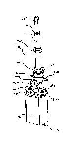
[0010] Fig. 1A is an isonne1ric view of an irrigating toothbrush.
[0011] Fig. 1B is an isome1ric partially exploded view of the irrigating
toothbrush of Fig.
1A.
[0012] Fig. 1C is a rear isometric partially exploded view of the
irrigating toothbrush of
Fig. 1A.
2
Date recue/Date Received 2023-11-14
[0013] Fig. 2A is cross-section view of the irrigating toothbrush of
Fig. 1A taken along
line 2A-2A in Fig. 1A.
[0014] Fig. 2B is an enlarged view of the lower section of Fig. 2A.
[0015] Fig. 2C is an enlarged view of the upper section of Fig. 2A.
[0016] Fig. 3A is an exploded view of an irrigating toothbrush handle.
[0017] Fig. 3B is a side elevation view of an irrigating toothbrush
handle.
[0018] Fig. 3C is a cross-section view of an irrigating toothbrush
handle taken along line
3C-3C in Fig. 3B.
[0019] Fig. 4A is a rear elevation view of a chassis assembly for the
irrigating toothbrush
handle of Fig. 1A.
[0020] Fig. 4B is an exploded view of a chassis assembly for the
irrigating toothbrush of
Fig. 1A
[0021] Fig. 5A is a top isometric exploded view of an end cap assembly
for the irrigating
toothbrush of Fig. 1A.
[0022] Fig. 5B is a bottom isometric exploded view of an end cap
assembly for the
irrigating toothbrush of Fig. 1A.
[0023] Fig. 5C is a top isometric view of the end cap assembly of Fig.
5A.
[0024] Fig. 5D is a rear elevation view of the end cap assembly of Fig.
5A.
[0025] Fig. 5E is a cross-section view of the end cap assembly of Fig.
5A taken along
line 5D-5D in Fig. 5D.
[0026] Fig. 6A is a top isometric view of a removable fluid connector
for the irrigating
toothbrush of Fig. 1.
[0027] Fig. 6B is a rear elevation view of the removable fluid connector
of Fig. 6A.
[0028] Fig. 6C is a cross-section view of the fluid connector of Fig. 6A
taken along line
6C-6C in Fig. 6B.
[0029] Fig. 6D is an exploded view of the fluid connector of Fig. 6A.
[0030] Fig. 7A is a top isometric view of a power train assembly of the
irrigating
toothbrush of Fig. 1A.
[0031] Fig. 7B is a top isometric exploded view of a power train
assembly of the
irrigating toothbrush of Fig. 1A.
[0032] Fig. 8A is a front elevation view of the power train assembly of
Fig. 7A.
3
Date recue/Date Received 2023-11-14
[0033] Fig. 8B is a side elevation view of the power train assembly of
Fig. 7k
[0034] Fig. 80 is a top plan view of the power train assembly of Fig.
7A.
[0035] Fig. 8C is a cross-section view of the power train assembly of
Fig. 7A taken along
line 8D-8D in Fig. 8A.
[0036] Fig. 9A is a rear isometric view of a rocker arm for the power
train assembly of
Fig. 7A.
[0037] Fig. 9B is a top plan view of the rocker arm of Fig. 9A.
[0038] Fig. 9C is a cross-section view of the rocker arm of Fig. 9A
taken along line 9C-
9C in Fig. 9B.
[0039] Fig. 10A is a side view of the power train assembly of Fig. 7A
illustrating a
misaligned output shaft axis in the front plane.
[0040] Fig. 10B is a cross-section view of the power train assembly of
Fig. 7A illustrating
a misaligned output shaft axis in the front plane taken along line 10B-10B in
Fig. 10A.
[0041] Fig. 100 is a front view of the power train assembly of Fig. 7A
illustrating a
misaligned output shaft axis in the side plane.
[0042] Fig. 10D is a cross-section view of the power train assembly of
Fig. 7A illustrating
a misaligned output shaft axis in the side plane taken along line 10D-10D in
Fig. 100.
[0043] Fig. 10E is a front view of the power train assembly of Fig. 7A
illustrating a
misaligned output shaft axis in both the front and the side plane.
[0044] Fig. 10D is a side view of the power train assembly of Fig. 7A
illustrating a
misaligned output shaft axis in both the front and the side plane.
[0045] Fig. 11A is a front bottom isometric view of a brush head for the
irrigating
toothbrush of Fig. 1A.
[0046] Fig. 11B is a top rear isometric view of the brush head of Fig.
11A.
[0047] Fig. 11C is a bottom plan view of the brush head of Fig. 11A.
[0048] Fig. 11D is a cross-section view of the brush head of Fig. 11A
taken along line
11D-11D in Fig. 11C.
[0049] Fig. 12A is a front bottom exploded view of the brush head of
Fig. 11A.
[0050] Fig. 12B is a top rear exploded view of the brush head of Fig.
11A.
[0051] Fig. 13A is a side elevation view of the fluid connector
connected to the end cap
assembly of the irrigating toothbrush of Fig. 1A.
4
Date recue/Date Received 2023-11-14
[0052] Fig. 13B is a rear elevation view of the fluid connector
connected to the end cap
assembly of Fig. 13A.
[0053] Fig. 130 is a cross-section view of the fluid connector connected
to the end cap
assembly of Fig. 13A taken along line 13C-13C in Fig. 13A illustrating the
fluid connector
latch in the latched position.
[0054] Fig. 13D is a cross-section view of the fluid connector connected
to the end cap
assembly of Fig. 13A similar to 130 illustrating the fluid connector latch in
the unlatched
position.
[0055] Fig. 14A is a cross-sectional view of the fluid connector
connected to the end cap
assembly of Fig. 13A taken along line14A-14A in Fig. 13B.
[0056] Fig. 14B is a cross-sectional view of the fluid connector
connected to the end cap
assembly of Fig. 13A taken along line 14B-14B in Fig. 13A.
[0057] Fig. 15A is a front elevation view of select components of the
power train
assembly of Fig. 7B illustrating the orientation of the eccentric prior to
installation.
[0058] Fig. 15B is a cross-section view of select components of the
power train
assembly of Fig. 7B taken along line 15B-15B.
[0059] Fig. 150 is a front elevation view of select components of the
power train
assembly of Fig. 7B illustrating the orientation of the eccentric after
installation but before
rotating into the operating position.
[0060] Fig. 15D is a cross-section view of select components of the
power train
assembly of Fig. 7B taken along line 15D-15D.
[0061] Fig. 16A is a cross-section view of the irrigating toothbrush
taken along line 16-16
in Fig. 3B illustrating the power train assembly in a first position.
[0062] Fig. 16B is a cross-section view of the irrigating toothbrush
similar to Fig. 16A
illustrating the power train assembly in a second position.
[0063] Fig. 17 is a side isometric view of an irrigating system
including an irrigating
toothbrush and a base unit.
[0064] Fig. 18A is a top isometric view of a motor and eccentric
assembly including a
one-piece eccentric component.
[0065] Fig. 18B is an exploded view of the motor and eccentric assembly
of Fig. 18A.
[0066] Fig. 19A is a top isometric view of a motor and eccentric
assembly including a
two-piece eccentric component.
Date recue/Date Received 2023-11-14
[0067] Fig. 19B is an exploded view of the motor and eccentric assembly
of Fig. 19A.
[0068] Fig. 20A is an isometric view of a second example of an
irrigating toothbrush.
[0069] Fig. 20B is a rear elevation view of the irrigating toothbrush of
Fig. 20A.
[0070] Fig. 21 is an exploded view of the irrigating toothbrush of Fig.
20A.
[0071] Fig. 22A is a front elevation view of a front chassis for the
irrigating toothbrush of
Fig. 20A.
[0072] Fig. 22B is a rear elevation view of the front chassis of Fig.
22A.
[0073] Fig. 23A is a front elevation view of a rear chassis for the
irrigating toothbrush of
Fig. 20A.
[0074] Fig. 23B is a rear elevation view of the rear chassis for the
irrigating toothbrush of
Fig. 20A.
[0075] Fig. 24A is an isometric view of an end cap assembly for the
irrigating toothbrush
of Fig. 20A.
[0076] Fig. 24B is a left side elevation view of the end cap assembly of
Fig. 24A.
[0077] Fig. 25A is a rear isometric view of a fluid connector for the
irrigating toothbrush
of Fig. 20A.
[0078] Fig. 25B is a cross-section view of the fluid connector of Fig.
25A taken along line
25B-25B in Fig. 25A.
[0079] Fig. 26A is an isometric view of a power train assembly for the
irrigating
toothbrush of Fig. 20A.
[0080] Fig. 26B is an exploded view of the power train assembly of Fig.
26A.
[0081] Fig. 27A is a front elevation view of the power train assembly of
Fig. 7A.
[0082] Fig. 27B is a side elevation view of the power train assembly of
Fig. 7A.
[0083] Fig. 27C is a cross-section view of the power train assembly of
Fig. 26A taken
along line 27C-27C in Fig. 27A.
[0084] Fig. 27D is a top plan view of the power train assembly of Fig.
26A.
[0085] Fig. 28A is a rear isometric view of a rocker arm for the power
train assembly of
Fig. 26A.
[0086] Fig. 28B is a top plan view of the rocker arm of Fig. 9A.
6
Date recue/Date Received 2023-11-14
[0087] Fig. 280 is a cross-section view of the rocker arm of Fig. 28B
taken along line
28C-28C in Fig. 20B.
[0088] Fig. 29A is a side view of the power train assembly of Fig. 26A
illustrating a
misaligned output shaft axis in the front plane.
[0089] Fig. 29B is a cross-section view of the power train assembly of
Fig. 26A
illustrating a misaligned output shaft axis in the front plane taken along
line 29B-29B in Fig.
10A.
[0090] Fig. 290 is a front view of the power train assembly of Fig. 26A
illustrating a
misaligned output shaft axis in the side plane.
[0091] Fig. 29D is a cross-section view of the power train assembly of
Fig. 26A
illustrating a misaligned output shaft axis in the side plane taken along line
29D-29D in Fig.
29C.
[0092] Fig. 29E is a front view of the power train assembly of Fig. 26A
illustrating a
misaligned output shaft axis in both the front and the side plane.
[0093] Fig. 29D is a side view of the power train assembly of Fig. 26A
illustrating a
misaligned output shaft axis in both the front and the side plane.
[0094] Fig. 30A is a front elevation view of select components of the
power train
assembly of Fig. 26B illustrating the orientation of the eccentric prior to
installation.
[0095] Fig. 30B is a cross-section view of select components of the
power train
assembly of Fig. 7B taken along line 30B-30B.
[0096] Fig. 300 is a front elevation view of select components of the
power train
assembly of Fig. 26B illustrating the orientation of the eccentric after
installation but before
rotating into the operating position.
[0097] Fig. 30B is a cross-section view of select components of the
power train
assembly of Fig. 7B taken along line 30B-30B.
[0098] Fig. 31A is a cross-section view of the irrigating toothbrush of
Fig. 20A illustrating
the power train at a first position.
[0099] Fig. 31B is a cross-section view of the irrigating toothbrush of
Fig. 20A illustrating
the power train at a second position.
DETAILED DESCRIPTION
[00100] The present disclosure is generally related to an irrigating,
electrically driven
toothbrush. The brushing device provides a flow path for fluids, as well as
drives an
7
Date recue/Date Received 2023-11-14
oscillating toothbrush to allow a user to irrigate his or her mouth and/or
brush his or her
teeth. The present system provides a power train that converts constant rotary
motion into
oscillating rotary motion. The power train also helps to conserve energy by
including
conservation features that absorb rotational momentum and return momentum in
the
opposite direction, which act to reduce the electrical power required to
operate the motor by
reversing the rotational momentum at the end of travel. The reduction in
electrical power
increases the number of cycles per battery charge for the system and the
conservation
members also act to reduce stress on the components of the power train,
extending the
operational life of the system.
[00101] In one embodiment, the conservation features may include spindles
including
compressible bumpers, such as 0-rings or other rubber elements that compress
to absorb
momentum and expand to reapply the momentum back to the power train
components.
[00102] In another embodiment, the conservation features are flexible
wings that are
operably connected to the power train and are secured to an inner housing or
chassis. In
this embodiment, the flexible wings deform as the output shaft rotates in a
first direction to
absorb energy and return to their original shape as the output shaft rotates
in a second
direction. In this manner, the flexible wings, which may function as beams or
leaf springs,
increase the efficiency of the system and reduce the electrical power required
to drive the
brush head. Specifically, the wings deflect in a first direction to absorb
momentum and
straight or return to their original shape to reapply momentum back to the
output shaft in the
second direction. As the output shaft may be oscillated, the first and second
directions may
be along an arc and the wings may reapply/absorb momentum at the beginning/end
of the
two directions or along the entire pathway. Additionally, in some embodiments,
the
conservation features may be positioned on opposite sides of the output shaft
to act to
absorb or reapply energy in opposite directions simultaneously.
[00103] In some embodiments, the conversation features may have a cross
section that
tapers in one or two directions as it approaches the terminal end. For
example, in
embodiments where the conservation features are wings, the wings may taper in
thickness
(e.g., along the Y axis) from a first end to a second end and may also vary in
width (e.g.,
along the Z axis) from the first end to the second end. The variation in two
directions
reduces stress concentrations on the wings, as well as helps to evenly
distribute the load. In
these embodiments, the wings may function as beams that absorb and distribute
stress and
the load is evenly applied along the length.
[00104] In embodiments where the conservation features include flexible
wings, a
terminal end of the wings may be pinched between to chassis components or
within a gap
8
Date recue/Date Received 2023-11-14
defined by an integral chassis. For example, a front chassis and a second
chassis may
connect together to define two opposing slots positioned on opposite sides of
the output
shaft. In this example, the terminal end of each wing is received and pinched
within the slot.
However, the slot is configured to allow the wings to move slightly within the
slot. In other
words, the slot provides some additional space that still pinches the wings to
force the wings
to deform (rather than rotate), but does not overly constrict the wings in
such a manner that
would cause the wings to crack or snap, as well as provides some "slop" to
allow easier
manufacturing and assembly. The size of the slot and the amount of gap between
the edges
defining the slot and the terminal end of the wings may be varied as desired
and as the wing
changes shape the size and configuration of the slot may vary correspondingly.
[00105] The system may also include a removable brush head that includes a
fluid path
that delivers fluid from a drive shaft of the power train (fluidly connected
to an irrigating
countertop unit) to a user's mouth via a flexible nozzle on the brush head
face. The
removable brush head allows different users to use the system, as each user
can use a
specific brush head.
[00106] The system also includes a removable water connection at the base of
the
toothbrush that fluidly connects the toothbrush to a reservoir and pumping
source. The
water connection or fluid connector may be configured to swivel 360 degrees so
that the
hose between the reservoir and the device moves to allow a user to use the
irrigating
brushing device without tangling the hose. The removable water connection also
includes a
valve that closes when the hose is removed, to prevent water from the
irrigating countertop
unit from leaking out. The removable water connection further allows the
toothbrush to be
used separately from the rest of the system, e.g., while a user is traveling.
[00107] In some embodiments, the irrigating brushing device may use a
continuously
rotating input driver (e.g., a direct current or alternating current motor)
that operates a
balanced power train assembly to change the continuous rotation of the input
driver into a
desired oscillating output motion, which drives the attached toothbrush head
at a sonic
speed or speeds.
[00108] Use of direct current (DC) drive motors for input drive motion
may result in a
lower production cost of the irrigating brushing system than the current
electro-magnetic
sonic toothbrush systems as well as the use of relatively inexpensive molded
plastic
components.
[00109] The irrigating brushing disclosed herein may provide a
continuously rotating input
drive system that provides oscillating, sonic-speed toothbrush output motion
with an
9
Date recue/Date Received 2023-11-14
extremely low level of mechanical vibration and noise. Also, the exemplary
systems
disclosed herein provide a sonic toothbrush system at a reduced production
cost.
[00110] Some embodiments of a toothbrush may be configured for attachment to a
dental
irrigating base unit. In these embodiments, the toothbrush may include a fluid
inlet for
connection with a fluid tube from the base unit. A fluid flow conduit is
provided through the
handle of the sonic toothbrush and also through a portion of the oscillation
drive motion
mechanism. The fluid flow conduit exits through a replaceable brush tip that
carries an
irrigator nozzle mounted within the bristles on the brush head. When the brush
tip is
attached to the output shaft of the handle, the internal water path of the
brush tip is sealed
with the outlet of the fluid flow conduit through the output shaft. This
provides a continuous,
sealed water path through the power handle up to and out of the water jet
nozzle located
between the toothbrush bristles.
[00111] An external, dental irrigating base system that generates a
pulsed water jet is
attached to an inlet port on the handle via a hose. When activated, this water
jet generating
system supplies a stream of pulsed or constant water which passes through the
handle,
through the brush tip, and exits from the nozzle within the toothbrush head
bristle pattern.
This water jet can be directed along the gum line to provide the water
flossing effect of a
standard, standalone water flosser. The base unit pumps water or other fluids
from a
reservoir in the base unit, through the connection hose, through the fluid
pathway in the
sonic toothbrush, and out the irrigator tip in the brush head to provide an
irrigating brushing
device in combination with the benefits of a toothbrush.
[00112] The handheld device disclosed herein provides a much more
compact, efficient,
and less costly "combination" toothbrush/water irrigation unit. With only one
handheld
device, considerable space is saved by not having to accommodate a second
handle, and
the space utilization can be more efficient. In addition, a single handle
affords the potential
for the combined system to be more economical. The detachable water source
also allows
the power handle to function untethered as a toothbrush for travel or when the
brushing
function is desired to be more portable. The single handle has the capability
to control both
the toothbrush function as well as the water jet function. In addition, a
single, replaceable
toothbrush head provides for both the brushing function as well as a
directable nozzle for the
water jet function without the requirement for separate, dedicated attachments
to provide
each of the two functions.
[00113] Turning now to the figures, an illustrative irrigating toothbrush
will now be
discussed in more detail. Fig. 1A illustrates an isometric view of the
irrigating toothbrush.
Fig. 1B illustrates an isometric view of the irrigating toothbrush with the
fluid connector and
Date recue/Date Received 2023-11-14
brush head removed. 1C illustrates a rear isometric view of the irrigating
toothbrush with the
fluid connector and brush head removed. With reference to Figs. 1A-2, the
irrigating
toothbrush 100 may be in the form of a handheld device and include a handle
102 with a
brush assembly 104 and fluid connector 110 removably connected thereto. The
removability
of the brush assembly 104 allows a user to replace the brush assembly 104 as
desired and
allows multipole users to hygienically use the same irrigating toothbrush 100.
The brush
assembly 104 includes a plurality of bristles 106 and in embodiments where the
device 100
includes an irrigating mode, a nozzle 108 is connected to the brush assembly
104 and is
embedded within the bristles 106.
[00114] The irrigating brushing device 100 also includes one or more
control buttons 114
that selectively activate and deactivate the various functions and/or modes of
the irrigating
toothbrush 100. The control buttons 114 may be connected to the handle 102 or
any other
convenient location for the user. As discussed below with reference to Fig.
16, the control
buttons 114 can control the brushing functions of the irrigating brushing
device 100, such as
activating the oscillation of the brush assembly 104, as well as control the
irrigating
functions, such as the water pressure and pulse length by communicating with a
base unit.
The number and function control of the control buttons 114 may be varied based
on the
desired functionality of the system.
[00115] The handle 102 is defined by a housing 118 that extends between a base
end 230 and a brush end 232. The housing 118 may be generally cylindrical in
shape to
ergonomically fit in the hand of a user, but it may be formed in any other
desirable
ergonomic shapes. The cylindrical shape may taper in the direction of the
brush end 232
approximately one third the length of the housing 118 from the brush end 232.
A face
plate 234 may be supported on the housing 118 in a region extending about the
control
buttons 114 as either a separate plate or as an overmolded surface on the
housing 118.
The housing 118 may further expose one or more status indicators 236a-236e
e.g., one or
more light emitting diodes, for indicating a mode or status of operation of
the irrigating
brushing device 100. Exemplary modes may be low speed, high speed, or water
flosser
mode. Exemplary status indications may be low battery, charging, and fully
charged battery.
[00116] With reference to Figs. 1A-1C, the irrigating toothbrush 100 may
include an
irrigating function and in these embodiments includes a fluid connector 110
for connecting
the handle 102 to a fluid source. Typically, the fluid connector 110 includes
a hose 112 that
is in fluid communication with a reservoir and/or pumping system for pumping
fluid through
the hose 112 to the nozzle 108. An example of a pumping system that may be
fluidly
connected to the hose 112 is shown in U.S. Patent No. 8,641,649 entitled "Pump
for Dental
Water Jet," filed on June 25, 2010. However, in other embodiments, the hose
112 may be
11
Date recue/Date Received 2023-11-14
connected directly to a pressurized water source, such as a faucet or J-pipe.
The fluid
connector 110 is removable from the handle 102 to allow the device 100 to be
used without
a fluid source, e.g., in brush only mode, and allow easier storage and
traveling. Additionally,
as will be disused in more detail below, the fluid connector 110 can be
configured to rotate
relative to the handle 102.
[00117] With reference to Figs. 1C and 3, the handle 102 includes a handle
housing
assembly 103, a chassis assembly 105, a latch button 231, and a retainer 233,
Generally,
the retainer 233 retains the chassis assembly 105 inside the handle housing
assembly 103.
The latch button 231 actuates the fluid connector latch 156 to release the
fluid connector
110.
[00118] With reference to Figs. 2A-2C and 4A-4B, the chassis assembly 105
includes a
power train assembly 130, a circuit board assembly 134, a battery assembly
136, an end
cap assembly 132, a front chassis 122, a back chassis 124, a fluid tube 142, a
boot seal
138, as well as various fittings, fasteners, and other connectors that assist
in securing
various components together. Generally, the battery assembly 136 provides
power to the
circuit board assembly 134, which operates the power train assembly 130 to
oscillate the
brush assembly 104 connected thereto, with the chassis 122, 124 providing
support for the
internal components of the chassis assembly 105 and the tube 142 providing a
fluid pathway
from the fluid connector 110 to the nozzle 108. The power train assembly 130
may also
include one or more of the conservation features. The conversation features
may be
operably connected to or form a part of the power train assembly. Each of the
various
components of the irrigating toothbrush 100 will be discussed in turn below.
[00119] The end cap assembly 132 forms a bottom end of the irrigating
toothbrush device
100 and fluidly connects the device 100 to the fluid connector 110, and also
serves as a
charging device for the battery assembly 136. Figs. 5A and 5B are exploded
views of the
end cap assembly 132. Figs. 50 and 5D illustrate various views of the end cap
assembly
132. Fig. 5E is across-section of the end cap assembly 132 taken along line 5D-
5D in Fig. 5
D. With reference to Figs. 5A-5E, the end cap assembly 132 includes an upper
end cap 148,
a lower end cap 150, a charging assembly 191, a charging assembly
encapsulation 155, a
fluid connector latch 156, and a cap valve assembly 190.
[00120] The bobbin 152 and core 154 are configured to define an electromagnet
that
induces current in response to magnetic fields to charge the battery assembly
136. For
example, a charge coil 153, such as copper wire, may be wrapped around the
bobbin 152
and core 154 to create an induction charging assembly. Other charging
assemblies may be
used as well, and the induction assembly is just one example.
12
Date recue/Date Received 2023-11-14
[00121] The upper end cap 148 is a generally cylindrical member that includes
an upper
cavity 172 defined on its upper end by an outer wall 194. The outer wall 194
may include an
annular groove 176, as well as one or more securing apertures 180a, 180b, 180c
defined
through. A valve wall 182 extends upward from a bottom surface 192 of the
upper end cap
148 to define a valve cavity 168 positioned within the upper cavity 172. For
example, the
valve cavity 168 may be a cylindrically shaped cavity nested within the upper
cavity 172.
[00122] One or more ribs 170 may be defined along an interior surface of the
valve wall
182 and may be defined as one or more longitudinal ribs extending along a
length or a
portion thereof of the valve wall 182. A tube connector 174 including a slot
173 defined in an
outer wall extends downward from the bottom surface 192 of the upper end cap
148. The
tube connector 174 may be a generally cylindrical protrusion that defines a
fluid pathway
therethrough. The fluid pathway of the tube connector 174 is fluidly connected
to the valve
cavity 168. For example, the tube connector 174 may be positioned on an
opposite side of
the bottom surface 192 from the valve cavity 168 and an aperture may be
defined through
the bottom surface 192 to fluidly connect the valve cavity 168 and tube
connector 174.
[00123] The lower end cap 150 is somewhat similar to the upper end cap 148 and
may be
a generally cylindrically shaped member defining a fitting cavity 184 and a
bobbin cavity 186.
The two cavities 184, 186 are separated by a dividing wall 196. The dividing
wall 196 helps
to prevent fluid from the fitting cavity 184 from entering into the bobbin
cavity 186 (which
includes the charging components). A top end of the fitting cavity 184 may be
surrounded
on two sides by planar surfaces 238a, 238b, each surface 238a, 238b including
a peg 200a,
200b extending upwards therefrom.
[00124] With reference to Figs. 5C and 5D, the lower end cap 150 may also
include a
latch engagement wall 201 defined on an outer surface thereof. The latch
engagement wall
201 may be formed as a relatively smooth surface that curves around a portion
of the
exterior of the lower end cap 150 defining the fitting cavity 184. Beneath the
latch
engagement wall 201, two arm compartments 202 are defined by outwardly
extending
flanges 199a, 199b that are separated by a portion 198 of the outer wall.
[00125] With reference again to Fig. 5A, the latch 156 is used to selectively
secure the
fluid connector 110 to the end cap assembly 132. For example, with brief
reference to Fig.
2B and 3, a latch button 231 accessible on the outside of the housing 118
allows a user to
activate the latch 156. With reference again to Fig. 5A-50, the latch 156
includes two latch
arms 166a, 166b connected to a latch body 240. The terminal ends of the latch
arms 166a,
166b may include an aperture defined through a center of the ends of the arms
166a, 166b
and a beveled shaped engagement end. The latch arms 166a, 166b include a wedge
13
Date recue/Date Received 2023-11-14
shaped leaf spring 242a, 242b extending inwardly in opposing directions
section, with a first
leaf spring 242a being positioned closer to a top end of the latch body 240
and the second
leaf spring 242b positioned closer to a bottom end of the lateral body. The
leaf springs
242a, 242b provide flexibility for the latch 156 and are configured to flex.
In one
configuration, the tail sections 242a, 242b curve away from the latch body 240
inward
between the latch arms 166a, 166b to interface with the latch engagement wall
201.
[00126] With reference to Figs. 5A, 5B and 5E, the valve assembly 190 for the
end cap
assembly 132 includes a valve cap 162, a poppet spring 160, and a poppet 158.
The valve
cap 162 includes a connection nipple 164 formed on a top surface towards a
first end of the
cap 162 and a spring post 244 formed on a bottom surface towards a second end
of the cap
162, such that the nipple 164 and the spring post 244 are offset from one
another and
formed on opposite surfaces of the cap 162. The nipple 164 is hollow and
defines a fluid
pathway therethrough, whereas the spring post 244 may be solid. The spring 160
wraps
around the spring post 244 and engages with a top end of the poppet 158.
[00127] The fluid connector 110 will now be discussed in more detail. Figs. 6A-
6C
illustrate various views of the fluid connector 110. Fig. 6D is an exploded
view of the fluid
connector 110. The fluid connector 110 fluidly connects the tube 142 with the
hose 112
fluidly connected to a fluid source (e.g., dental irrigator base unit with a
reservoir, etc.). With
reference to Figs. 6A-6D, the fluid connector 110 includes a fitting 206, a
hose 112, a tube
collar 210, a sealing member 226, a fitting top cap 228, a bottom cap assembly
208, and a
valve assembly 204. The bottom cap assembly includes a bottom cap 214, a pin
216, and a
retainer 218. The valve assembly 204 includes a spring bearing 220, a spring
212, a poppet
222, and a poppet cap 224.
[00128] The pin 216 is used to provide a magnetic attraction to a base unit to
support the
fluid connector 110 on a base unit, described below. The pin 216 may be any
type of
material having magnetic properties, including, for example, steel, iron,
nickel, or the like.
[00129] The fitting 206 defines a housing that houses and retains the valve
assembly 204
within a cavity 245 defined therein. The fitting 206 may be L-shaped defining
a fluid
passageway 246 there through. The fitting bottom cap assembly 208 is fitted
within a
bottom end of the fluid pathway 245 to seal the bottom end of the fitting 206.
The bottom
cap assembly 208 may be sonically welded or otherwise adhered to the fitting
206 to provide
a fluid tight seal. The bottom cap 214 may include a pin cavity 248 defined
therein that
receives the pin 216. The retainer 218 may be sonically welded or otherwise
adhered to the
bottom cap 214 to provide a fluid tight seal for the pin cavity 248. The
fitting top cap 228
includes an annular groove 227 within an outer wall thereof and connects to a
top end of the
14
Date recue/Date Received 2023-11-14
fitting 206. The top cap 228 may also define an internal annular recess 229 in
which the
sealing member 226 (e.g., a U-cup) seats. The tube collar 210 may include a U-
shaped clip
bracket 211 and a tube clamp 213 that fit over a hose 112 and around an outer
surface of
the fitting 206 to secure the hose 112 to the fitting 206.
[00130] The power train assembly 130 will now be discussed in more detail.
Figs. 7A-8D
illustrate various views of the power train 130. The power train assembly 130
powers the
output shaft 116 and defines the output motion of the brush assembly 104. The
power train
130 includes a motor 250, a mount plate 252, an eccentric 260, a rocker arm
262, bumpers
264a, 264b, the output shaft 116, and one or more sleeve bearings 268, 270. In
this
embodiment, the rocker arm 262 and/or bumpers 264a, 264 b may together define
the
conservation features. However, as discussed in more detail below, in other
embodiments,
the rocker arm 262 alone or in combination with other elements may define the
conservation
features for the device. Additionally, the power train 130 may include one or
more fasteners
254a, 254b an 0-ring seal 280, and a seal retainer 266.
[00131] The motor 250 may be substantially any type of device that converts
electrical
energy into mechanical energy. In some embodiments, the motor 250 may be a
direct
current motor. The motor 250 includes a drive shaft 256 with an eccentric
portion 258
integrally formed therewith. In other words, a single drive shaft 256 includes
two separate
longitudinal axes, a first axis aligned with approximately a central region of
the motor 250
and a second axis offset from the first axis.
[00132] It should be noted that in other examples, the eccentric portion
258 may be
formed in other manners. For example, Figs. 18A and 18B illustrate various
views of a
motor 650 including a drive shaft 652 with an eccentric component connected
thereto, rather
than being formed integrally with the drive shaft. With reference to Figs. 18A
and 18B, in this
example, the eccentric 654 includes a base portion 656 and a post 658
extending from a top
surface of the base 656. The eccentric 654 connects to the drive shaft 652 and
the post 658
forms an output shaft for the motor 650 and is eccentric relative to an output
axis of the
motor 650. As another example, Figs. 19A and 19B illustrate an example of a
motor 650
including a two-piece eccentric 654. In this example, the base portion 656' is
received
around the drive shaft 652 and the post 658' is received into an aperture or
cavity defined in
the base portion 656 and extends out from the base portion 656 to form the
output shaft of
the motor 650. However, in embodiments, where the motor includes an integral
drive shaft
with a bent or eccentric portion, the number of components for the device can
be reduced,
reducing manufacturing costs, reducing complexity of the product, and
increasing reliability.
[00133] With reference again to Figs. 7A-80, the eccentric 260 of the power
train
assembly 130 connects to the drive shaft 256 and includes a drive shaft
aperture 276 for
Date recue/Date Received 2023-11-14
receiving the drive shaft 256. The eccentric 260 may be a disc shaped member
and the
drive shaft aperture 276 is offset from the center of the eccentric 260. In
one example, the
drive shaft aperture 276 is adjacent an outer perimeter edge of the eccentric
260. The
eccentric may have a spherical outer surface 261.
[00134] The sleeve bearings 268, 270 are configured to be received around a
portion of
the output shaft 116. The sleeve bearings 268, 270 help to cushion the output
shaft 116 and
reduce friction with the chassis 122, 124 as the output shaft 116 oscillates.
The sleeve
bearings 268, 270 may have a spherical outer mounting surface 269, 271 that is
configured
to be received within a corresponding mounting feature within the chassis.
Although the
bearings 268, 270 are discussed as sleeve bearings, in other embodiments other
types of
cushioning elements can be used, such as ball bearings.
[00135] The rocker arm 262 defines the oscillating movement of the output
shaft 116 and
helps to conserve energy for the power train and the brush. Figs. 9A-9B
illustrate various
views of the rocker arm 262. With reference to Figs. 9A-9B, the rocker arm 262
includes a
main body 290 including two spindles 272a, 272b or arms extending laterally
outward from a
right side and a left side, respectively, of the main body 290. The two
spindles 272a, 272b
are axially aligned with each other and each may include an annular groove
292a, 292b
within an outer surface on a terminal end thereof for receiving a bumper
element 264a,
264b, which may be a compressible component, such as an 0-ring or other rubber
component. In some embodiments, the spindles 272a, 272b may be flexible and
may
engage a sidewall or interior surface of the housing or chassis to conserve
energy. In other
embodiments, the spindles 227a, 272b may include an additional deformable
member, such
as a rubber 0-ring that deforms against the interior surface to absorb and
reapply energy to
the rocker arm 262. Another example of the rocker arm and spindles is shown in
Figs. 26A-
26D.
[00136] The rocker arm 262 also includes a fluid connector 294 extending
downward from
the main body 290. The fluid connector 294 is configured to connect to a fluid
tube and may
include a male or female connector, and in one embodiment includes a barb as
shown in
Fig. 9k Depending on the configuration of the housing and size of the
irrigating toothbrush
100, the fluid connector 294 may be arranged at various angles relative to the
main body
290. For example, as shown in Fig. 9A, the fluid connector 294 may extend
downward at an
angle relative to the main body 290, rather than being perpendicularly
oriented relative to the
spindles 272a, 272b. However, in other embodiments, the fluid connector 294
can be
otherwise arranged.
[00137] With continued reference to Figs. 9A-9B, a cylindrical outer wall 300
extends
upwards from the top end of the main body 290. The outer wall 300 defines a
shaft cavity
16
Date recue/Date Received 2023-11-14
288 formed on the top end of the main body 290, The shaft cavity 288 is in
fluid
communication with the fluid connector 294 via a fluid passage defined through
the main
body 290. The diameter of the shaft cavity 288 may be varied to assist in
retaining the
output shaft 116 and other components. For example, the rocker arm 262 may
include a
locking feature 296 extending into the shaft cavity 288 from an interior
surface and optionally
an annular shelf 298 extending into the shaft cavity 288 from an interior
surface arranged
closer to the top end of the outer wall 300 from the locking feature 296. The
shaft cavity 288
includes interior surfaces that contact the seal 280. The seal retainer 266
helps to secure the
seal 280 within the shaft cavity 288 and provides support on the outside
portion of the seal
280. In other configurations the seal retainer 266 can be integrated into the
output shaft 116
In a one-piece design. In some embodiments, the rocker arm 262 can be
ovenolded onto
the output shaft 116 to form a watertight seal without additional seal
elements. Other
features and configurations are also envisioned.
[001381 The rocker arm 262 also includes a cam follower 284 that extends from
a front
surface of the main body 290. The cam follower 284 is a hollow bracket
structure that
defines an eccentric cavity 286. With reference to Fig. 7B and 9A-9C, the
eccentric cavity
286 may have a socket 287 to receive the outer surface 261 of the eccentric
260. In
embodiments where the outer surface of the eccentric 260 is spherically
shaped, the socket
287 may be correspondingly spherically shaped. The socket 287 of the cam
follower 284
allows the axis of the eccentric 260 to rotate such that the axis of the motor
drive shaft 256
and the axis of the output shaft 116 can have an angular misalignment in one
of two planes
or both planes simultaneously as shown in Figs. 10A-10F. Due to the angular
misalignment
allowed between the axis of the motor drive shaft 256 and the axis of the
output shaft 116,
when the handle 102 experiences an impact event that causes the chassis 122,
124 to flex,
the motor 250 can move with respect to the output shaft 116, allowing the
power train
assembly 130 to be less susceptible to damage. In addition, less precise motor
mounting
tolerances can be used because parallel mounting of the motor drive shaft 256
and the
output shaft 116 is not required. Further, the position of the motor 250 can
be angled in the
handle 102 to optimize space for other components, while maintaining the
desired
orientation of the output shaft 116.
[001391 Various tips can be used with the irrigating toothbrush device 100.
One example
of a brush tip that can be used with the irrigating toothbrush device is
disclosed in U.S.
Publication No. 2014/0259474 entitled "Mechanically-Driven, Sonic Toothbrush
and Water
Flosser" filed March 17, 2014.
Another example is shown in Figs. 11A-12B, which illustrate various views of
one example of
a tip. With reference to Figs. 11A -128, the brush assembly 104 includes a tip
shaft 308 with
17
Date recue/Date Received 2023-11-14
a brush head 320. The tip shaft 308 defines a tip fluid passage 322
therethrough to the
brush head 320. The brush head 320 defines a bristle base 324 composed of a
plurality of
recesses into which a plurality of bristle tufts 106 may be inserted and
secured in place. In
addition, the brush head 320 defines a nozzle aperture 107 that opens in the
bristle base
324 in an area surrounded by bristle tufts 106. A trim ring 316 may be
attached to the base
340 of the tip shaft 308 to allow for multiple users of the device 100 to
easily identify their
personal brush assembly 104 for attachment to the handle 102. For example, the
trim ring
316 may be various colors to identify different user's brushes. The base 340
of the tip shaft
308 may define a recess with a retention groove 326. The inner wall of the
colored trim
ring 316 may define a number of retention detents 328 that may snap into the
retention
groove 326 to retain the colored trim ring 316 around the base of the brush
assembly 104.
[00140] An elastomeric jet nozzle 108 is positioned within the nozzle
aperture 107 and
extends normal to the bristle base 324 approximately the same distance as the
bristle
tufts 106. The nozzle 108 defines a fluid lumen, is generally conical, and
tapers in diameter
from its base to its tip. A cavity 330 is formed in the back of the brush head
320 to provide
access to the nozzle aperture and a fluid flow connection between the nozzle
aperture and
the tip fluid passage 322. The cavity 330 may be enclosed by a brush head plug
304 that
snaps into the sidewalls defining the cavity 330 and is ultrasonically welded
or otherwise
adhered to provide a fluid-tight seal in the brush head 320.
[00141] A cylindrical recessed band 334 is formed in a sidewall of the
nozzle 108
adjacent the base, which thus appears as a raised band 336. The outer diameter
of the
recessed band 334 is generally congruent with the diameter of the nozzle
aperture while the
outer diameter of the recessed band 334 is larger than the diameter of the
nozzle aperture.
When the nozzle 108 is inserted into the nozzle aperture from the cavity 330
in the rear of
the brush head 320, the recessed band 334 fits snugly within the nozzle
aperture 107 and
the raised band 336 abuts the back of the bristle base 324, preventing the
nozzle 108 from
being pushed through the nozzle aperture when under pressure. In addition, a
nozzle
insert 306, e.g., a brass tube with a rear flange, may be inserted into the
base of the
nozzle 108 to prevent the nozzle 108 from bending or collapsing under high
water pressure
and contact with teeth and thereby dislodging from the nozzle aperture.
[00142] A retainer 310 may be inserted into and permanently affixed
within the tip fluid
passage 322 from the base end 340 of the tip shaft 308. In the exemplary
implementation
shown, the retainer 310 may be generally formed as a frustum with open
sidewalls. A top
ring 350 is joined to a larger diameter bottom ring 352 by an alignment rib
354 on one side
and a support rib 356 laterally opposed thereto. The top ring 350 defines an
outlet
aperture 358.
18
Date recue/Date Received 2023-11-14
[00143] A sealing element 312, such as a U-cup, may be inserted into the
tip fluid
passage 322 of the tip shaft 308 after the retainer 310 and may be held in
place against the
retainer 310 by an end cap 314. In this exemplary implementation, the end cap
314 is
formed as a series of stacked cylinders with decreasing diameters as they
extend toward the
brush head 320. The end cap 314 defines a lumen 360 through which the output
shaft 116
passes when the brush assembly 104 is placed on the handle 102. The retainer
posts 362a-
362d extend outward from the sidewall of the bottom end of the end cap 314.
When the end
cap 314 is inserted into the lumen 338 of the tip shaft 308, the base end 340
deflects and
deforms to allow installation of the retainer posts 362a-362d of the end cap
314. The
alignment slot 364 of the end cap 314 nests onto the alignment rib 332 inside
the lumen 338
of the tip shaft 308 ensuring alignment of the retainer posts 362a-362d of the
end cap 314 to
the retainer apertures 361a-361d of the tip shaft 308.
[00144] Clip slots 366a-366d are also formed in the sidewall of the end
cap 314. The clip
slots 366a-366d extend transversely through the end cap 314. The clip slots
366a-366d are
configured to retain a spring retainer clip 318 therein to secure the output
shaft 116 to the
brush assembly 104. The spring retainer clip 318 may be formed from a piece of
stiff wire to
have a pair of clip arms 368a, 368b that oppose each other and are joined at a
clip arch 370.
The free ends of the clip arms 368a, 368b each form a reverse curve that opens
away from
the other. When the retainer clip 318 is installed in the clip slots 366a-
366d, the clip
arch 370 extends outside the end cap 314, the middle sections of the clip arms
368a, 368b
are retained within the clip slots 366a-366d in the front wall, and the free
ends of the clip
arms 368a, 368b are exposed outside of the end cap 314.
Assembly of the Irriaatina and Brushina Device
[00145] Assembly of the irrigating toothbrush device 100 will now be
discussed. It should
be noted that although the below discussion outlines examples of an ordering
assembly,
many other assembly orders and manufacturing techniques and ordering are
anticipated and
the below discussion is meant as illustrative only.
[00146] With reference to Figs. 6A-6D for assembly of the removable fluid
connector 110,
the bottom cap assembly 208 is assembled by inserting the steel pin 216 into
the pin cavity
248 of the fitting bottom cap 214. The retainer 218 is then positioned on the
top end of the
fitting bottom cap 214 and secured into place when the slot 380 fits around
the nub 382 on
the top end of the fitting bottom cap 214. The valve assembly 204 is assembled
by pressing
the poppet cap 224 onto the top end of the poppet 222. The top end of the
spring 212 is then
sleeved over a portion of the lower section of the poppet 222. The lower
section of the spring
212 is then sleeved over a portion of the spring bearing 220 such that the
spring spans
19
Date recue/Date Received 2023-11-14
between the bearing 220 and the poppet 222. The spring bearing 220 is seated
on top of
the retainer 218 with the post 384 of the retainer 218 extending into a cavity
defined by the
spring bearing 220 to secure the spring bearing 220 to the retainer 218. The
valve assembly
204 and the bottom cap assembly 208 are then inserted within the cavity 245 of
the fitting
206, and the bottom cap 214 is secured to the fitting 206 by a sonic weld or
by another
bonding method to form a fluid tight seal. The sealing element 226 is received
within the
fitting top cap 228 and the fitting top cap 228 is secured to the top end of
the fitting 206 by a
sonic weld or by another bonding method to the top end of the fitting 206 to
form a fluid tight
seal. The hose 112 is received around the barb 386 extending from a sidewall
of the fitting
206 and the tube collar 210 is slipped over the hose 112 so that a friction
fit against the hose
112 in the location of the tube clamp 213 is formed. The arms of the U-shaped
clip bracket
211 snap around an outer surface of the fitting 206, such as within a
predefined groove or
recession around the outer surface of the fitting 206.
[00147] Assembly of the end cap assembly 132 will now be discussed. With
reference to
Figs. 5A-5E, conductive wiring is wrapped around the bobbin 152 multiple turns
to form a
conductive charge coil 153, and then the core 154 is positioned on the bobbin
152 with a
middle section of the core 154 being positioned between the two upwardly
extending prongs
of the bobbin 152 and the outer sections of the core 154 being positioned
outside two of the
outer edges of the bobbin 152 such that the conductive charge coil 153 that
wraps around
an outer surface of the bobbin 152 will extend between the two outer sections
of the core
154. The charging assembly 191 is then received in the bobbin cavity 186 of
the lower end
cap 150 and secured therein by submersing or encapsulating the charging
assembly 191
with an adhesive or potting material 155 to form a waterproof encapsulation. A
non-
encapsulating attachment method using a mechanical fastener or an adhesive
bond may
also be used; however the encapsulation method provides better protection for
the
components in the charging assembly 191 if the handle 102 experiences an
impact event or
a water leak.
[00148] With continued reference to Figs. 5A-5E, the latch 156 is connected to
the lower
end cap 150 with apertures in each of the latch arms 166a, 166b being received
around
pegs 200a, 200b of the planar surfaces 238a, 238b and the latch body 240 and
the leaf
springs 242a, 242b interfacing against the outer surface of the latch
engagement wall 201.
[00149] After the latch 156 is connected to the lower end cap 150, the upper
end cap 148
is connected to the lower end cap 150 by a sonic weld or by another bonding
method to form
a fluid tight seal between the bobbin cavity 186 and the upper end cap 148. In
particular, the
tube connector 174 is aligned with the fitting cavity 184 of the lower end cap
150, and the
latch holes 203a, 203b are positioned over the pegs 200a, 200b of the lower
end cap 150.
Date recue/Date Received 2023-11-14
In this manner, the upper end cap 148 seats on the top end of the lower end
cap 150.
Before or after the upper end cap 148 is connected to the lower end cap 150,
the valve
assembly 190 is inserted into the upper end cap 148. Specifically, the poppet
158 is
positioned in the valve cavity 168 of the upper end cap 148 and the spring 160
is seated on
the top end of the poppet 158 between the one or more ribs 170. The cap 162 is
then
connected to the spring 160 with the spring post 244 being received into the
center of the
spring 160, such that the spring 160 wraps around the spring post 244. The cap
162 seats
on the top edge of the valve wall 182 by a sonic weld or by another bonding
method to form
a fluid tight seal.
[00150] The assembled removable fluid connector 110 and the end cap assembly
132
may be connected together to fluidly connect the irrigating toothbrush 100
with the base unit,
as described below. Figs. 13A-14D illustrate various views of the fluid
connector 110
connected to the end cap assembly 132. With reference to Figs. 14C and 14D,
the top end
of the removable fluid connector 110, specifically, the fitting top cap 228
and top end of the
fitting 206 are inserted into the fitting cavity 184 of the lower end cap 150.
Before the fluid
connector 110 is inserted into the end cap assembly 132 and pressurized fluid
flows into the
end cap assembly, the poppet 158 seals against the outlet of the tube
connector 174 to
prevent fluid remaining within the device 100 from a prior use from leaking
out of the device
100 via the tube connector 174.
[00151] As the fluid connector 110 is inserted into the end cap assembly,
the tube
connector 174 of the upper end cap 148 is inserted into the center of the
fitting top cap 228
and extends into the fitting 206 to press against the poppet cap 224. The
force of the tube
connector 174 compresses the spring 212 moving the poppet cap 224 and poppet
222
downward towards the spring bearing 220 and retainer 218. In this
configuration, the poppet
cap 224 and poppet 222 are pressed downward away from the top end of the
fitting 206 to
allow fluid to flow around the poppet cap 224 and poppet 222 through the slot
173 defined in
the outer wall of the tube connector 174 and into the internal flow path in
the tube connector
174.
[00152] With reference to Fig. 13C, 13D, and 14D, when the fluid
connector 110 is initially
inserted into the end cap assembly 132, the latch arms 166a, 166b of the latch
156 are
forced outwards and slide on the pegs 200a, 200b. To insert the fluid
connector 110 a user
is not required to compress the latch button 231 on the housing, but rather
due to the
beveled configuration of the fitting top cap, the fitting connector 110 can
insert directly into
the end cap assembly 132 and the latch 156 will clip automatically to the
fitting 110. In
particular, as the user continues to insert the fluid connector 110 into the
fitting cavity 184,
21
Date recue/Date Received 2023-11-14
the leaf springs 242a, 242b deform to allow the latch arms 166a, 166b to move
outward in
this manner.
[00153] Once the fluid connector 110 is in position, the leaf springs
242a. 242b spring
back to the original configuration, forcing the latch arms 166a, 166b to move
inwards and
engage with the annular groove 227 on the fitting top cap 228 to secure the
fluid connector
110 to the end cap assembly 132. As the annular groove 227 extends around the
entire
outer perimeter of the fitting top cap 228, the latch arms 166a, 166b can
maintain their
engagement with the fitting top cap 228, while still allowing the fluid
connector 110 to rotate.
In other words, as the fluid connector 110 swivels, the latch arms 166a, 166b
travel along
the groove 227, continuing to secure the fluid connector 110 to the end cap
assembly 132.
while allowing the fluid connector 110 to rotate relative thereto. This allows
the fluid
connector 110 and hose 112 to rotate relative to the handle 102, such that as
a user is using
the device 100, the hose 112 can move to stay out of the user's way, and the
hose 112 is
less likely to tangle.
[00154] Similarly, to release the fluid connector 110 from the end cap
assembly 132, a
user presses against a button 231 connected to the housing 118, which
compresses the
latch body 240, compressing the leaf springs 242a, 242b, deforming them and
causing the
latch arms 166a, 166b to pivot outwards, disengaging from the groove 227 of
the fitting top
cap 228, allowing the fluid connector 110 to be removed.
[00155] Assembly of the power train assembly 130 will now be discussed. With
reference
to Figs. 7A-9C, the 0-ring seal 280 and the seal retainer 266 are received
around the shaft
281 on the bottom end of the output shaft 116. The terminal end of the output
shaft 116,
including the 0-ring seal 280 and the seal retainer 226 are received into the
shaft cavity 288
of the rocker arm 262. With reference to Fig. 8D, once the output shaft 116 is
inserted into
the shaft cavity 288, the fluid passageway 115 defined through the
longitudinal length of the
output shaft 116 is fluidly connected to the fluid connector 294 of the rocker
arm 262.
[00156] The output shaft 116 includes a locking feature, key, or surface,
such as a locking
groove, flat surface, or the like, which is aligned with the locking feature
296 of the rocker
arm 262 to prevent the output shaft 116 from moving relative to the rocker arm
262 so that
the output shaft 116 will move with the rocker arm 262. The sleeve bearings
268, 270 are
received at spatially discrete locations along the length of the output shaft
116. The location
of the sleeve bearings 268, 270 may be varied based on the configuration,
size, motor
speed, housing configuration, and other design configurations.
[00157] With continued reference to Figs. 7A-9C and reference to Figs. 15A-
15E, the
eccentric 260 is then positioned so that the eccentric axis 297 is
perpendicular to the cam
22
Date recue/Date Received 2023-11-14
follower axis 299 of the rocker arm 262. The eccentric 260 is then inserted
into the eccentric
cavity 286 of the rocker arm 262 such that the installation force applied to
the eccentric 260
causes the cam follower structure 284 to deflect into an elongated oval shape
to allow the
installation of the eccentric 260. The eccentric 260 is then rotated so that
the eccentric axis
297 is collinear with the cam follower axis 299. The mounting plate 252 is
secured to the
motor 250 by the fasteners 254a, 254b. The eccentric portion 258 of the drive
shaft 256 is
inserted into the aperture 276 of the eccentric 260. Each of the bumpers 264a,
264b are
received in the grooves 292a, 292b on the spindles 272a, 272b of the rocker
arm 262.
[00158] With reference to Figs. 2A-2C and 4B, once the power train assembly
130 is
connected, the battery assembly 136 and the motor 250 are electrically
connected to the
circuit board assembly 134. For example, the prongs 274 of the motor 250 may
be
connected via wires or contacts to the circuit board assembly 134 and,
similarly, contacts on
the battery assembly 136 may be connected via wires to the circuit board
assembly 134.
[00159] The front chassis 122 and back chassis 124 are then connected around
the
battery assembly 136 and power train assembly 130. Each of the chassis 122,
124 include
specifically designed compartments for each of the components of the battery
assembly 136
and power train assembly 130. For example, front and back chassis 122, 124
together
define a rocker arm cavity that allows the rocker arm 262 to oscillate, but
provides a surface
for the bumpers 264a, 264b to engage with and exert a force against the
surfaces of the
chassis 122,124. As another example, each of the front and back chassis 122,
124 may
include a slot for receiving a portion of the mounting plate 252 to secure the
power train
assembly 130 in a desired location relative to the front and back chassis 122,
124. The front
chassis 122 and back chassis 124 may be connected together via fasteners 126a-
126g and
corresponding nuts 128a-128 g.
[00160] With reference to Fig. 4A, 4B, 5A, 5E and 8B, after the front
chassis 122 and
back chassis 124 are secured together, the 0-ring seal 146 is installed in the
annular groove
176 of the lower end cap 150. The battery retention spring 133 is then fitted
around the
spring locating rib 197 of the upper end cap 148. The end cap assembly 132 is
then fitted
onto the lower sections of the connected chassis 122, 124 so that the prong
181 of the front
chassis 122 and the prongs 183a, 183b of the back chassis 124 engage the
securing
apertures 180a-180c of the end cap assembly 132. The collars 144a, 144b are
slid on the
tube 142. The tube 142 is then connected to the fluid connector 294 of the
rocker arm 262.
Specifically, a first end of the tube 142 is press fit onto the fluid
connector 294 and the collar
144b is secured around the fluid connector 294 and tube 142, securing the tube
142 to the
rocker arm 262. The second end of the tube 142 is then inserted onto the
nipple 164 of the
cap 162 of the end cap assembly 132. Collar 144a is then received around the
nipple 164
23
Date recue/Date Received 2023-11-14
and tube 142 to secure the tube 142 to the cap 162. In this manner the tube
142 fluidly
connects the valve assembly 190 and fluid connector 110 to the rocker arm 262
and output
shaft 116. The boot ring 140 is then fitted in the annular groove of the boot
138. The boot
138 is then slid over the output shaft 116 and fitted to the top end of the
connected chassis
122, 124 so that the boot ring 140 clamps the top end of the boot 138 onto the
output shaft
116 to form a watertight seal.
[00161] With reference to Figs. 3A-3C, the handle 102 is assembled by
sliding the
retainer 233 into the two arm compartment 202 of the lower end cap 150. The
latch button
231 is fitted into the aperture 119 of the handle housing assembly103. The
handle housing
assembly 103 is then received over the chassis assembly 105 while compressing
the
retainer nubs 235a, 235b inwardly so that they provide clearance to the handle
housing
assembly 103. The chassis assembly 105 is fitted inside the handle housing
assembly 103
such that the retainer nubs 235a, 235b spring outwardly into the retention
pockets 121a,
121b and so that the output shaft 116 is the only component that extends out
of the handle
housing assembly 103. The retainer nubs 235a, 235b of the retainer 233 assist
in securing
the various internal components in a desired position in the handle housing
assembly 103
and help to prevent movement of the components during operation of the
irrigating and
brushing device 100. The boot seal 135 and the 0-ring seal 146 of the chassis
assembly
105 are compressed by the inside walls of the handle housing assembly 103 to
provide an
upper and lower water tight seal for the internal components of the handle
102.
[00162] Once the device 100 is assembled, the brush assembly 104 may be
connected to
the output shaft 116. The user places the brush assembly 104 onto the output
shaft 116 and
rotates the brush assembly 104 until an alignment flat 351 (see Fig. 1B) of
the output shaft
116 mates with a keyed surface of the retainer 310. Then, the user presses the
brush
assembly 104 onto the output shaft 116 until the lateral arms 368a, 368b of
the spring
retainer clip 318 seat within the clip recess 353 (see Fig. 1B). The diameter
of the output
shaft 116 increases along a beveled edge immediately adjacent the clip recess
353. The
clip arms 368a, 368h of the spring retainer clip 318 expand laterally outward
along this edge
and then, when past the beveled edge, the clip arms 368a, 368b contract
laterally inward to
lodge within the clip recess 353. Typically, an audible "click" can be heard
by the user when
the clip arms 368a, 368b lodge within the clip recess 353 so that the user
knows that the
brush assembly 104 is securely attached to the handle 102. The gauge, material
strength,
and elasticity of the wire forming the spring retainer clip 318 are
specifically chosen to
ensure retention of the brush assembly 104 on the output shaft 116 under the
operating
pressures of the water jet function and further to reliably expand during
engagement and
24
Date recue/Date Received 2023-11-14
disengagement of the brush assembly 104 over an appropriate number of cycles
equivalent
to or greater than an estimated life of the bristles 106.
[00163] To disconnect a brush assembly 104 from the output shaft 116, the
user pulls the
brush assembly 104 away from the handle 102 with a sufficient force to
overcome the force
exerted by the clip arms 368a, 368b, which causes the arms to deform and slide
out of the
clip recess 353, allowing the brush assembly 104 to be removed.
Operation of the Irrigating Brushing Device
[00164] To operate the irrigating toothbrush device 100 with an
irrigating function the user
first connects the fluid connector 110 to the handle 102 (if not already
connected) by
inserting the fitting 206 into the end cap assembly 132 as discussed above to
open the valve
assembly of the fluid connector 110. The user then activates a pumping
assembly, such as
one connected to a countertop or base oral irrigation unit to pump fluid from
a reservoir to
the hose 112. With reference to Figs. 2A-2B and 14A-14B, the fluid flows into
the fitting 206
from the hose 112 and flows around the fitting bottom cap 214 and around the
poppet 222
and poppet cap 224 into the tube connector 174 of the end cap assembly 312.
The fluid
force pushes against the poppet 158 in the valve assembly 190, overcoming the
biasing
force exerted by the poppet spring 160, allowing fluid to exit the tube
connector 174 and
enter the valve cavity 168.
[00165] With continued reference to Fig. 2A-2B and 14A-14B, the fluid
flows around the
poppet 158 and into the nipple 164 of the cap 162. With reference to Figs. 2A-
2B and 4A,
fluid flows from the nipple 164 of the cap 162 into the tube 142. The fluid
flows through the
tube 142 into the fluid connector 294 of the rocker arm 262. From the fluid
connector 294,
the fluid flows into the fluid passageway 115 of the output shaft 116 via the
aperture shaft
cavity 288. With reference to Fig. 2A-2B, 11D and 12B, the fluid flows through
the
passageway 115 and exits through the aperture 358 and sidewall openings of the
retainer
310 and enters into the fluid passageway 322 of the tip shaft 308. From the
fluid
passageway 322, the fluid flows into the end of the brush assembly 104 and
into the nozzle
108 and exits into a user's mouth.
[00166] With reference to Figs. 1A and 2A-2B, during or after irrigation,
to activate the
brush function, the user selects one of the control buttons 114, such as an
off/on switch, to
activate the brush function. In particular, when the on/off control button is
selected a contact
on the circuit board assembly 134 is activated and power from the battery
assembly 136 is
provided to the motor 250, causing the drive shaft 256 to rotate.
[00167] Figs. 16A and 16B illustrate across-section view of the
irrigating brushing device
100 taken along line 16 in Fig. 3B. Fig. 16A illustrates the power train
assembly 130 in a first
Date recue/Date Received 2023-11-14
position and Fig. 16B illustrates the power train assembly 130 in a second
positon. As the
drive shaft 256 rotates, the eccentric portion 258 connected to the drive
shaft 256 rotates,
due to the mounting constraints of the output shaft 116, this creates an
oscillating rotary
motion in the eccentric 260 centered about the axis of the eccentric 260
within the eccentric
cavity 286 of the cam follower 284. This causes the cam follower 284 to move
correspondingly in an oscillating rotary motion centered about the axis of the
output shaft
116. Additionally, due to the constraints of the front and back chassis 122,
124, the
movement of the rocker arm 262 is restricted. Specifically, as the cam
follower 284 moves
with the eccentric 260, the rocker arm 262 rotates, causing the spindles 272a,
272b to move
back and forth. With reference to Fig. 16A, as the first spindle 272a moves in
a first direction
D1, the second spindle 272b moves in an opposite second direction D2. In other
words, the
rocker arm 262 rocks back and forth within the cavity defined by the front and
back chassis
122, 124 with the degrees of movement being defined by the continuous
rotational motion of
the eccentric portion 258 of the drive shaft 256 and by the mounting
restraints of the
bearings 268, 270 on the output shaft 116.
[00160] With reference to Fig. 16A, when the spindles 272a, 272b reach the end
of their
rotational travel in the respective first and second directions D1, D2, the
bumpers 264a,
264b engage the bumper surface 430a of the front chassis 122 and bumper
surface 432b of
the back chassis 124 respectively and compress, absorbing rotational momentum.
With
reference to Fig. 16B, as the rocker arm 262 continues to move the spindles
272a, 272b
begin to reverse their rotational directions and the bumpers 264a, 264b
expand, returning
momentum to the spindles 272a, 272b as they do so. In this manner, the bumpers
264a,
264b assist in reducing the electrical power required to operate the motor 250
by reversing
the rotational momentum at the end of travel, which in turn increases the
number of cycles
per battery charge that the motor 250 can be operated. Further, the bumpers
264a, 264b
help to reduce the stress on the component parts of the device 100, such as
the components
of the power train 130, to further extend the life of the device 100. In
embodiments, where
the spindles 272a, 272b themselves form the deformable members (e.g., are made
of
flexible materials), the ends of the spindles 272a, 272b may directly engage
the interior
surfaces of the front chassis 122 and back chassis 124 in order to absorb and
reapply
energy. In these instances, the 0-rings or other deformable materials may be
omitted.
[00169] As the rocker arm 262 oscillates, with the movement constrained by the
front and
back chassis 122, 124, the output shaft 116 connected thereto oscillates with
the rocker arm
262. The bearings 268, 270 cushion the output shaft 116 as it rotates within
the chassis
122, 124 to help reduce vibrations from being transmitted to the user holding
the handle 102.
The oscillations of the output shaft 116 cause the brush assembly 104, which
is connected
26
Date recue/Date Received 2023-11-14
thereto by the end cap 314 and retainer 310, to oscillate as well. Because the
entire brush
assembly 104 oscillates and the fluid flows through the output shaft 116, the
brush
mechanism can be used simultaneously with the irrigating operation. However,
while both
the brushing and irrigating functions can be used simultaneously, each of
these functions
can also be used independently from each other.
[00170] As the brush assembly 104 is oscillating the user may place the
bristles 106
against surfaces within his or her mouth, such as teeth, gums, etc. As the
user moves the
irrigating toothbrush 100 to reach different locations in his or her mouth,
the fluid connector
110 can rotate to ensure that the hose 112 does not get tangled or
inadvertently pulled from
the handle 102. Due to the connection features of the fluid connector 110, as
described
above, the fluid connector 110 can rotate 360 degrees. Additionally, as the
end cap
assembly 132 includes a sealing valve that seals the tube connector 174 when
the fluid
connector 110 is removed, the irrigating toothbrush 100 can be used without
the fluid
connection to the base unit, i.e., in a brushing only mode, allowing multiple
uses of the same
device and allowing a user to travel with only the handle 102 portion of the
system.
Communication with Base Unit
[00171] As mentioned above, the irrigating toothbrush 100 may be in fluid
communication
with a reservoir and base unit. Fig. 17 illustrates a perspective view of an
irrigating system
500 including the irrigating toothbrush 100 and a base unit 501. The base unit
501 may be
an oral irrigating countertop unit and includes a reservoir 502, a base 504
housing a
pumping system (not shown), and one or more base controls 506. The base unit
501 also
includes a communication module 512 for communicating with a corresponding
communication module 510 on the device 100. In one embodiment, the
communication
modules 510, 512 may be radio wave communication modules, using short distance
communication protocols, such as Bluetooth, WiFi, ZigBee, or the like, that
transmit and
receive radio wave signals. For example, a user may activate one or more of
the control
buttons 114 on the device 100 in order to change the fluid pressure output by
the pumping
system of the base unit 501 and/or activate or deactivate the irrigating
function. In this
example, the communication module 510 on the device 100 transmits the pressure
control
signal to the communication module 512, which then provides the signal to the
pumping
system. In this manner, the user can dynamically adjust the pressure,
selectively turn on/off
the system 500, and/or control other characteristics of the system 500 such as
activating a
massage mode feature, etc.
[00172] In other embodiments, the irrigating brushing device 100 may
communicate with
the base unit 501 in other manners, such as a wired connection. For example,
the hose 112
27
Date recue/Date Received 2023-11-14
may include wires extending between the two devices that are connected to
and/or
embedded within the hose 112. In these instances the communication wires may
be
shielded from the fluid within the hose 112.
Alternative Embodiments
[00173] Other examples of the irrigating toothbrush will now be
discussed. It should be
noted that in the discussion below elements that are the same between
embodiments have
the same numbering. Additionally, any of the features described with respect
to any
particular embodiment may be used with any other embodiment.
[00174] Figs. 20A-21 illustrate various views of another embodiment of
the irrigating
toothbrush with certain features hidden. With reference to Figs. 20A-21, in
this embodiment,
the irrigating toothbrush 700 may be substantially similar to the irrigating
toothbrush 100 but
may include a modified power train assembly 730, end cap assembly 732, and
fluid
connector. Additionally, due to changes with the power train assembly 730, a
chassis
assembly 705 including a front chassis 702 and rear chassis 704 (or first
chassis and
second chassis) may be varied as compared to the first embodiment. Each of
these
components will be discussed in turn below.
[00175] With reference to Figs. 22A and 22B, the front or first chassis
702 is configured to
define an internal structure that houses and defines a scaffold for the power
train assembly
730. The front chassis 702 includes an outer surface 716 and an interior
surface 726, where
the interior surface 726 is configured to mate with the rear chassis 704 as
discussed below.
A top end 720 of the front chassis 702 defines a cylindrical outer surface
that optionally
includes one or more grooves to receive a sealing member, such as a boot seal
or 0-ring.
The front chassis 702 may also include one or more openings defined therein.
These
openings are configured to receive various components of the power train
assembly 730
(e.g., drive assembly, motor, and/or batteries). Additionally, the openings
are hollow and so
reduce the overall weight of the device 700. In some embodiments, the front
chassis 702
may include two brackets 722a, 722b that extend into a bottom cavity. The
brackets 722a,
722b may be used to secure the batteries (or other component) in a desired
position relative
to the internal components secured to the front chassis 702. A shaft channel
724 may be
defined through a central portion of the front chassis 702 on the rear
surface. The shaft
channel 724 may vary in width along its length to accommodate bearings or
other features
that may be received around the drive or output shaft 116.
[00176] With reference to Fig. 22B, a power train cavity 728 is defined
on the interior
surface 726 towards the top end 720. The power train cavity 728 includes a
back surface
and is recessed from the interior surface 726 (i.e., extends outwards towards
the outer
28
Date recue/Date Received 2023-11-14
surface 716). The power train cavity 728 is configured to receive and support
components
of the power train assembly 730, such as the conservation features (e.g.,
rocker arm).
[00177] A first engagement surface 734a and a second engagement surface 734b
are
defined on the two side edges of the power train cavity 728. The two
engagement surfaces
734a, 734b are recessed below the interior surface 726 but raised above the
power train
cavity 728. In some embodiments, the two engagement surfaces 734a, 734h are
defined as
planar surfaces that extend longitudinally along a portion of the length of
the power train
cavity 728 and the depth of the recess may vary along their length. As will be
discussed
below, the recessed depth of the engagement surfaces 734a, 734b defines, in
part, the width
of a slot for receiving wings of the power train assembly 730. Two angled
walls 736a, 736h
extend at an angle between the engagement surfaces 734a, 734b and the lateral
sidewall of
the power train cavity 728.
[00178] A bottom end of the front chassis 702 may include one or more
retaining features
781, such as prongs or nubs, that are configured to connect to the end cap
assembly 732 in
a similar manner as described with respect to the irrigating toothbrush 100 of
Fig. 1A. The
retaining features 781 may be spaced around the outer surface of the front
chassis 702.
[00179] With continued reference to Figs. 22A and 22B, the front chassis 702
may also
include a plurality of fastening apertures 718a-718g that are used to receive
fasteners to
secure the front chassis 702 to the rear chassis 704 in a similar way as the
front chassis 122
and rear chassis 124 for the irrigating toothbrush 100 are connected together.
[00180] With reference to Figs. 23A and 23B, the rear chassis 704 may be
somewhat
similar to the front chassis 702 and is configured to connect to the front
chassis 702. The
rear chassis 704 includes an outer surface 742 and interior surface 744. A top
end 740
includes a similar shape as the top end 720 of the front chassis 702 and is
configured to
mate with the top chassis 702 to define the shaft channel 724. Similar to the
front chassis
702, the rear chassis 704 includes a plurality of fastening apertures 738a-
738g positioned so
as to align with the corresponding fastening apertures 718a-718g of the front
chassis 702 to
allow the two chassis 702, 704 to be secured together with fasteners.
[00181] A plurality of retaining features 783a, 783b may be defined on the
bottom end of
the rear chassis 704 and are similar to the retaining features 781 on the
front chassis 702.
These retaining features 783a, 783b are configured to connect to the end cap
assembly 732
and secure it to the chassis 704.
[00182] The rear chassis 704 may define a power train cavity 745 having an
access
aperture 746 defined through the front wall thereof. The power train cavity
745 is configured
to receive and support various components of the power train assembly 730 and
the access
29
Date recue/Date Received 2023-11-14
aperture 746 allows the fluid tube142 to be connected to the power train
assembly 730 and
fluidly connect to the brush tip. In some embodiments a brace 748 may extend
across a
width of the access aperture 746 to provide support for the power train
components received
within the power train cavity 745, while still allowing the fluid tube to be
inserted through the
rear chassis 704 and connect to the power train assembly 730. The position and
size of the
brace 748 may be varied as desired.
[00183] With reference to Fig. 23B, similar to the front chassis 702, the
rear chassis 704
may include two engagement walls 735a, 735b positioned on a longitudinal edge
of the
power train cavity 745. The engagement walls 735a, 735b are recessed from the
interior
surface 744 and may be recessed at a taper, such as that a top end of the
engagement
walls 735as, 735b is closer to the interior surface 744 as compared to a
bottom end of the
engagement walls 735a, 735b. The depth of the recess for the engagement walls
735a,
735b defines, in part, a slot that the conservation features (as discussed
below) are received
within and helps to define the degrees of movement for the conservation
features. As such,
the recess depth may be varied as desired.
[00184] Angled walls 737a, 737b connect the interior edge of the engagement
walls 735a,
735b to the edge of the sidewalls of the power train cavity 745. The slope of
the angled
walls 737a, 737b may vary based on the size and configuration of the
conservation features.
[00185] The end cap assembly 732 will now be discussed. Figs. 24A and 24B
illustrate
various views of the end cap assembly 732. The end cap assembly 732 may be
substantially similar to the end cap assembly 132 and may connect to the
chassis 702, 704
and fluid connector in a similar manner as described above. With reference to
Figs. 24A and
24B, the end cap assembly 732 in this example may include a different
configuration for a
retainer 752. The retainer 752 connects the end cap assembly 752 to the outer
housing 103
of the irrigating brush 700. In one embodiment, the retainer 752 includes two
arms 754a,
754b that extend first perpendicular from a main section of the retainer 752
and then second
are extend parallel to the main section such that the arms 754a, 754b curve
around the outer
surface of a lower end cap 750. In this manner, a dip is defined in the
retainer 752 which
allows the bottom edge of the fluid connector latch 156 to be fit around the
lower end cap
750 and be able to move relative to the end cap 750 without interference from
the retainer
752.
[00186] Each of the arms 754a, 754b include retainer numbs 756a, 756b that
extend
outwards from the terminal end of the arms 754a, 754b. The retainer nubs 756a,
756b may
include a top beveled surface that transitions to a planar surface parallel to
the outer surface
Date recue/Date Received 2023-11-14
of the arms 754a, 754b. The nubs 756a, 756b are configured to engage with the
interior of
the housing similar to the retainer numbs 235a, 235b shown in Fig. 3C.
[00187] With reference to Fig. 24B, the retainer 752 may also include posts
758a, 758b
that extend downwards from the arms 754a ,754b below the nubs 756a, 756b. The
posts
758a, 758b connect to receiving brackets defined by a shelf 760 in the lower
end cap 750.
The posts 758a, 758b allow the arms 754a, 754b to pivot relative to the lower
end cap and
define the pivot axis for the arms 754a, 754b as the retainer 752 engages and
disengages
from the housing 103. In other examples, such as retainer 233, the posts may
be defined on
the lower end cap 150, rather than the retainer, but the functionality is
similar.
[00188] With the change to the retainer 752, the lower end cap 750 is
slightly different
from the lower end cap 150. In particular, a shelf 760 that defines a cutout
to define a
bracket for receiving the posts 758a, 758b of the retainer 752 is defined on
two sides of the
lower end cap 750. Accordingly, rather than the retainer being received in the
arm
compartments 202 as in the lower end cap 150, the retainer 752 is positioned
on the top
surface of the shelf 760 and the posts inserted into the cutouts defined by
the shelf 760.
[00189] In some embodiments, a modified fluid connector 766 having a
shorter height
may be connected to the irrigating toothbrush. Figs. 25A and 25B illustrate
various views
another example of a fluid connector 766 that connects to the irrigating
brush. With
reference to Figs. 25A and 25B, the fluid connector 766 may be substantially
similar to the
fluid connector 110, but include an alternate valve assembly that allows the
height of the
fluid connector 776 to be reduced. The reduced height allows the irrigating
toothbrush 700
to more easily connect to the base unit and be positioned in an upright
manner. The fluid
connector 766 may include a fitting 768 that is similar to the fitting 206 of
the fluid connector
110 but may have a shorter overall height. The fitting 768 includes a tube
connector 770
[00190] With reference to Fig. 25B, the valve assembly of the fluid
connector 766 is
similar to the valve assembly of the fluid connector 110 but includes a
modified poppet 776,
pin 774, and bottom cap 772. The poppet 776 includes a head portion and a
sleeve 778 that
extends downwards from the outer perimeter of the head portion. The sleeve 776
may be a
cylindrical shape and defines a cavity that receives the spring 212 for the
valve assembly.
The spring 212 seats on a post 775 extending downward from a center of the
head portion of
the poppet 766. The poppet 776 operates similar to the poppet 222 in the fluid
connector
110 but includes the sleeve 776 that at least partially encloses the spring
212. This
enclosure provides additional rigidity to the poppet 776 to help prevent the
poppet from
twisting or binding up during use.
31
Date recue/Date Received 2023-11-14
[00191] With continued reference to Fig. 25B, the fluid connector 766 may also
include a
pin 774, which may be a magnetic element, that has a reduced height as
compared to the
pin 216 in the fluid connector 110. In particular, in this example, the pin
774 may be shaped
as a circular disc as compared to the elongated cylindrical shape of the pin
216. The
increased width of the pin 774 may be configured to provide a similar magnetic
force to
connect the fluid connector 766 to the base unit as the elongated pin 216.
Alternatively, the
magnetic force of the pin 774 may be configured to exert an increased or
decreased
magnetic force.
[00192] The power train assembly 730 for the irrigating toothbrush 700 will
now be
discussed in more detail. Figs. 26A-27D illustrate the power train assembly
730. The power
train assembly 730 may be substantially similar to the power train assembly
130. However,
the power train assembly 730 may include an integrally formed conservation
component or
feature and a reduced width motor bracket. In particular, a rocker arm 780 for
the power
train assembly 130 may include wings 782a, 782b or spindles integrally formed
with the
main body of the rocker arm. The wings are configured to deform and spring
back to an
original shape and thus the deform able elements (e.g., 0-rings) or the rocker
arm 262 may
be omitted. The rocker arm 780 will be discussed in more detail below.
[00193] With respect to the motor bracket 783, in this embodiment, the bracket
may have
a reduced size to allow a thinner housing 103 for the irrigating toothbrush
700. In one
embodiment, motor bracket 783 forms a generally rectangular body having a
width that is
smaller than a width of the motor 250. Additionally, the bracket 783 tapers at
the two ends
to define tabs that extend from either end of the bracket 783. The tabs
provide additional
structure to secure motor and the bracket 783 to the interior of the front
chassis 702 and the
rear chassis 704 in a similar manner as the motor bracket 252, but allow the
housing to have
a decreased width as compared to other embodiments.
[00194] With reference to Figs. 28A-28C, the rocker arm 780 will be discussed
in more
detail. The rocker arm 780 is substantially similar to the rocker arm 262
includes sufficiently
flexible spindles or wings that deform, eliminating the separate deformable
members (0-
rings 264a, 264b). The rocker arm 780 includes a main body 790 including two
wings 782a,
782b or arms extending laterally outward from a right side and a left side,
respectively, of the
main body 790. The two wings 782a, 782b are axially aligned with each other
and as shown
in Figs. 28A and 28B taper in two directions, in their width and their
thickness as they extend
from the main body 790 outwards. In this manner, the terminal end of each of
the wings
782a, 782b is narrower both in width and thickness as compared to the
connected end of the
wings 782a, 782b. This dual taper helps to distribute stresses evenly across
the wings
782a, 782b, reducing stress concentrations in the wings 782a, 782b. It should
be noted that
32
Date recue/Date Received 2023-11-14
in other embodiments, the taper may be along a single axis only, e.g., only
the width (Y axis)
or the thickness (Z axis), or as shown in Figs. 28A and 28B along two lengths.
[00195] The rocker arm 780 also includes a fluid connector 794 extending
downward from
the main body 790. The fluid connector 794 is configured to connect to a fluid
tube and may
include a male or female connector, and in one embodiment includes a barb as
shown in
Fig. 28A. Depending on the configuration of the housing and size of the
irrigating toothbrush
700, the fluid connector 794 may be arranged at various angles relative to the
main body
790. For example, as shown in Fig. 28A, the fluid connector 794 may extend
downward at
an angle relative to the main body 790, rather than being perpendicularly
oriented relative to
the wings 782a, 782b. However, in other embodiments, the fluid connector 794
can be
otherwise arranged.
[00196] With continued reference to Figs. 28A-28B, a cylindrical outer
wall 800 extends
upwards from the top end of the main body 790. The outer wall 800 defines a
shaft cavity
788 formed on the top end of the main body 790. The shaft cavity 788 is in
fluid
communication with the fluid connector 794 via a fluid passage defined through
the main
body 790. The diameter of the shaft cavity 788 may be varied to assist in
retaining the
output shaft 116 and other components. For example, the rocker arm 780 may
include a
locking feature 796 extending into the shaft cavity 788 from an interior
surface and optionally
an annular shelf 798 extending into the shaft cavity 788 from an interior
surface arranged
closer to the top end of the outer wall 800 from the locking feature 796. The
shaft cavity 788
includes interior surfaces that contact the seal 280. The seal retainer 266
helps to secure the
seal 280 within the shaft cavity 788 and provides support on the outside
portion of the seal
280. In other configurations the seal retainer 266 can be integrated into the
output shaft 116
in a one-piece design. In some embodiments, the rocker arm 780 can be
overmolded onto
the output shaft 116 to form a watertight seal without additional seal
elements. Other
features and configurations are also envisioned.
[00197] The rocker arm 780 also includes a cam follower 784 that extends from
a front
surface of the main body 790. The cam follower 784 is a hollow bracket
structure that
defines an eccentric cavity 786. With reference to Fig. 28C, the eccentric
cavity 786 may
have a socket 787 to receive the outer surface 261 of the eccentric 260. In
embodiments
where the outer surface of the eccentric 260 is spherically shaped, the socket
787 may be
correspondingly spherically shaped. The socket 787 of the cam follower 784
allows the axis
of the eccentric 260 to rotate such that the axis of the motor drive shaft 256
and the axis of
the output shaft 116 can have an angular misalignment in one of two planes or
both planes
simultaneously as shown in Figs. 29A-29F. Due to the angular misalignment
allowed
between the axis of the motor drive shaft 256 and the axis of the output shaft
116, when the
33
Date recue/Date Received 2023-11-14
handle 102 experiences an impact event that causes the chassis 702, 704 to
flex, the motor
250 can move with respect to the output shaft 116, allowing the power train
assembly 730 to
be less susceptible to damage. In addition, less precise motor mounting
tolerances can be
used because parallel mounting of the motor drive shaft 256 and the output
shaft 116 is not
required. Further, the position of the motor 250 can be angled in the handle
102 to optimize
space for other components, while maintaining the desired orientation of the
output shaft
116. The rocker arm 780 of the irrigating toothbrush 700 connects to the
output shaft 116
and eccentric 260 in the same manner as the rocker arm 262. See, e.g., Figs.
30A-30E.
[00198] With reference to Figs. 21 and 22B, to assemble the rocker arm 780
within the
chassis 702, 704, the rocker arm 780 is positioned within the power train
cavity 728 and the
wings 782a, 782b are aligned with the engagement surfaces 734a, 734b of the
front chassis
702. The rear chassis 704 is then connected to the front chassis 704 with the
engagement
surfaces 735a, 735b aligning with the engagement surfaces 734a, 734b. With
reference to
Fig. 31A, the alignment of the engagement surfaces 734a, 734b, 735a, 735b
defines a slot
804 between the front chassis 702 and the rear chassis 704. The terminal end
of the wings
782a, 782b are positioned within this slot 804. In some embodiments, the slot
804 may have
a width that substantially matches the thickness of the wings 782a, 782b to
prevent any
movement of the wings 782a, 782b relative to the chassis 702, 704. In other
embodiments,
such as the one shown in Figs. 31A and 31B, the slot 804 is slight larger than
the width of
the wings 782a, 782b to allow easier assembly, prevent breaking of the wings,
while still
restraining large movements of the wings 782a ,278b. In this configuration,
the wings 782a,
782b of the rocker arm 780 are pinched or restrained to the chassis 702, 704
on opposite
sides of the output shaft 112. However, the width of the slot 804 may be
varied as desired.
[00199]
Operation of the power drive train 730 of the irrigating toothbrush 700 will
now be
discussed in more detail. Fig. 31A illustrates the output shaft 116 and the
rocker arm 780 in
a first position and Fig. 31B illustrates the output shaft 116 and the rocker
780 in a second
positon. With reference to Fig. 31A, as the motor 250 rotates the drive shaft
256, the
eccentric 260 rotates within the rocker arm 780, which causes the cam follower
784 of the
rocker arm 780 to rotate in direction R1. This causes the output shaft 116 and
wings 782a,
782b to pivot along the arc of rotation R1. At the end of the rotation arc R1,
the terminal end
of the first wing 782a engages the first engagement surface 734a of the front
chassis 702
and is prevented from moving further in the rotation direction R1. This causes
the wing 782a
to deflect or deform as the rocker arm 780 continues to rotate.
Simultaneously, the second
wing 782b engages the engagement surface 735b of the rear chassis 704 and
deforms in an
opposite direction. The flexibility of the wings 782a, 782b allows them to
deform without
shearing or breaking. This deformation absorbs momentum from the motor.
34
Date recue/Date Received 2023-11-14
[00200] With reference to Fig. 31B, as the motor continues to rotate the
drive shaft 256,
the movement of the eccentric 260 is constrained by the rocker arm 780 and the
rocker arm
780 pivots in a second rotation direction R2. This change in direction, causes
the output
shaft 112 to rotate along the second rotation arc in direction R2. At the
beginning of this
directional change, each of the wings 782a, 782b elastically return to their
original shape,
provide momentum back to the output shaft 116 via the rocker arm 780, reducing
drag and
enhancing efficiency of power train assembly 730. Then, as the rocker arm 780
continues to
rotate towards the end of the second arc rotation R2, the terminal ends of the
wings 782a,
782b engage the opposite engagement surfaces, e.g., wing 782a engages the
engagement
surface 735a of the rear chassis 704 and wing 782b engages the engagement
surface 734b
of the front chassis 702. During this engagement, the wings 782a, 782b are
prevented from
further rotation and begin to deform as they absorb energy. When the rocker
arm 780 pivots
to rotate in the first direction R1 again, the wings 782a, 782b will apply the
absorbed energy
to the rocker arm 780 as described above. Due to the orientation of the wings
and the
position on opposite sides of the output shaft, the wings may provide forces
at substantially
the same time to the output shaft.
[00201] Depending on the width of the slot 804, as well as the thickness
of the wings
782a, 782b, the wings 782a, 782b may be configured to provide or absorb energy
to the
rocker arm 780 at only the ends of the rotation arcs. However, in other
embodiments, the
wings may be configured to apply energy along the entirety of a particular
rotation direction.
Conclusion
[00202] Although the above description is discussed with respect to a
dual-function
device, in some embodiments, the features of the power train and other
components of the
handle 102 may be incorporated as a standalone brushing device. In other
words, although
an irrigation function is disclosed, the toothbrush may be used without the
irrigating. In these
embodiments, the components including a fluid path may be omitted or modified,
e.g., the
output shaft may be solid rather than hollow.
[00203] All directional references (e.g., proximal, distal, upper, lower,
upward, downward,
left, right, lateral, longitudinal, front, back, top, bottom, above, below,
vertical, horizontal,
radial, axial, clockwise, and counterclockwise) are only used for
identification purposes to aid
the reader's understanding of the present invention, and do not create
limitations, particularly
as to the position, orientation, or use of the invention. Connection
references (e.g., attached,
coupled, connected, and joined) are to be construed broadly and may include
intermediate
members between a collection of elements and relative movement between
elements unless
otherwise indicated. As such, connection references do not necessarily infer
that two
Date recue/Date Received 2023-11-14
elements are directly connected and in fixed relation to each other. The
exemplary drawings
are for purposes of illustration only and the dimensions, positions, order and
relative sizes
reflected in the drawings attached hereto may vary.
[00204] The above specification, examples and data provide a complete
description of
the structure and use of exemplary embodiments of the invention as defined in
the claims.
Although various embodiments of the claimed invention have been described
above with a
certain degree of particularity, or with reference to one or more individual
embodiments,
those skilled in the art could make numerous alterations to the disclosed
embodiments
without departing from the spirit or scope of the claimed invention. Other
embodiments are
therefore contemplated. It is intended that all matter contained in the above
description and
shown in the accompanying drawings shall be interpreted as illustrative only
of particular
embodiments and not limiting. Changes in detail or structure may be made
without
departing from the basic elements of the invention as defined in the following
claims.
36
Date recue/Date Received 2023-11-14