Note: Descriptions are shown in the official language in which they were submitted.
WO 2023/274917 1
PCT/EP2022/067492
AIRCRAFT LANDING GEAR ASSEMBLY
Background to the Invention
An aircraft landing gear assembly is generally movable between a deployed
condition, for
take-off and landing, and a stowed condition for flight.
An actuator is provided for moving the landing gear between the deployed
condition and
the stowed condition. This actuator is known in the art as a retraction
actuator, and more
than one can be provided. A retraction actuator can have one end coupled to
the airframe
and another end coupled to the main strut such that extension and retraction
of the
actuator results in movement of the main strut between the deployed and stowed
conditions.
A brace or stay is generally provided to support the orientation of the main
strut when the
landing gear is in the deployed condition. A stay generally includes a two bar
linkage that
can be unfolded to assume a generally aligned, over centre condition in which
the stay is
locked to inhibit movement of the main strut. When the stay is broken, it no
longer reacts
movement of the main strut and the main strut can be moved by the retraction
actuator
to the stowed condition. Some main landing gear assemblies include a pair of
stays coupled
to a common main strut.
A lock link is generally provided in conjunction with each stay to maintain
the stay in the
locked condition. A lock link generally includes a two bar linkage that can be
unfolded to
assume a locked over centre condition to inhibit movement of the stay. The
lock link must
be broken to enable the stay to be folded, thereby permitting the main strut
to be moved
by the retraction actuator towards the stowed condition.
It is common for a landing gear assembly to be arranged to move towards the
deployed
condition in the event of a failure of the retraction actuator. Initially, the
landing gear
assembly will move by way of gravity, and in doing so the stay is forced to
move towards
the locked condition. One or more down lock springs are generally provided to
assist in
moving the landing gear assembly to the deployed condition and locking it in
that state by
moving the lock link over centre. Down lock springs also inhibit the lock link
accidentally
being unlocked.
A down lock spring is generally a metal coil spring, which can be coupled
between the lock
link and another part of the landing gear assembly, such as an arm of the stay
assembly.
CA 03221503 2023- 12- 5
WO 2023/274917 2
PCT/EP2022/067492
However, more recent developments in landing gear assemblies have seen the use
of fibre
composite leaf springs, such as that described in European Patent Publication
No.
EP3069993. Fibre composite leaf springs can deflect sufficiently to
accommodate
articulation movement of the lock link as the landing gear assembly moves
between the
deployed and stowed conditions. The fibre composite leaf spring has various
advantages
over conventional metal coil down lock springs; for example, the leaf spring
can have a
low profile in comparison to a coil spring, reducing the likelihood of impact
damage, in
addition to being less susceptible to vibratory loading.
The present inventors have devised an improved landing gear assembly that can
have one
or more of the following advantages relative to known landing gear assemblies:
spring
lifespan; spring load profile; and/or weight of the landing gear assembly.
Summary of Invention
According to a first aspect of the invention, there is provided an aircraft
landing gear
assembly comprising: a first landing gear element movably coupled relative to
a second
landing gear element to pivot about a pivot axis between a first condition and
a second
condition; a cam surface spatially fixed with respect to the pivot axis; and a
leaf spring
having a first end region and a second end region, the first end region of the
leaf spring
being coupled to the first landing gear element to move with the first landing
gear element
and the second end region of the leaf spring comprising a cam follower
arranged in moving
contact with the cam surface such that the cam follower moves from a first
region of the
cam surface to a third region of the cam surface via a second region of the
cam surface
as the first landing gear element pivots about the pivot axis from the first
condition to the
second condition, bending the leaf spring, wherein the cam surface is shaped,
contoured,
arranged and/or configured such that a distance between the pivot axis and the
cam
surface increases between the first region and the second region to define a
first gradient
and a distance between the pivot axis and the cam surface varies between the
second
region and the third region of the cam surface to define a second gradient,
the second
gradient being less steep than the first gradient.
Thus, the landing gear assembly according to the first aspect includes a leaf
spring which
defines a cam follower acting on a cam surface arranged to provide a spring
load which is
not greater when the landing gear is stowed in comparison to an operational
condition.
When in the operational condition, the spring is arranged to urge the first
landing gear
element to assume the first condition, which can for example equate to a
landing gear
down-lock engaged operational condition. In this manner, spring fatigue can be
reduced,
CA 03221503 2023- 12- 5
WO 2023/274917 3
PCT/EP2022/067492
thereby increasing the lifespan of the leaf spring and reducing maintenance
requirements.
A further advantage relates to the assembly method, which can be easier to
perform when
compared to coil springs that require large and complex tools for
installation.
The landing gear assembly can comprise: a main strut arranged to be movably
coupled to
an aircraft to move between a deployed condition and a stowed condition; a
side stay
comprising a first stay member pivotally coupled to a second stay member, the
first stay
member being pivotally coupled to the strut and the second stay member being
arranged
to be pivotally coupled to an anchor point so as to be movable between a
locking condition
in which the side stay members are generally aligned to react a force
attempting to move
the main strut from the deployed condition towards the stowed condition, and a
passive
condition in which the side stay permits the main strut to be moved from the
deployed
condition towards the stowed condition; and a lock link comprising a first
lock link member
pivotally coupled to a second lock link member, the first lock link member
being pivotally
coupled to the strut and the second stay member being pivotally coupled to
side stay so
as to be movable between a locking condition in which the lock link members
are generally
aligned to react a force attempting to move the side stay from the locking
condition
towards the passive condition, and a passive condition in which the lock link
permits the
side stay to be moved from the locking condition towards the passive
condition, wherein
the first landing gear element comprises the first lock link member or the
second lock link
member.
With such an arrangement, the leaf spring can be mounted on one of the lock
link arms,
which enables the cam surface to be defined relative to a pivot pin mounting
of the lock
link.
The first landing gear element can comprises the first lock link member and
the first lock
link member can be pivotally coupled to the strut via a cardan pin, the second
landing
gear element comprising the cardan pin.
With such an arrangement, the head of the cardan pin can define the cam
surface, reducing
the weight of the landing gear assembly and simplifying its construction.
The first landing gear element can comprise the first lock link member and the
second
landing gear element can comprise the second lock link member, the cam surface
being
defined by an end region of the second lock link member via which the second
lock link
member is pivotally coupled to the first lock link member.
CA 03221503 2023- 12- 5
4
WO 2023/274917
PCT/EP2022/067492
The follower can be defined by an end fitting coupled at the second end region
of the leaf
spring, the end fitting having a first end region defining a mounting
formation via which
the end fitting is coupled to the leaf spring.
With such an arrangement, the end fitting can form a sacrificial part such
that the spring
is not worn through contact with the second element, the end fitting being
removably
coupled to the spring to enable replacement.
The end fitting can be formed of a relatively hard or malleable material in
comparison to
the spring; for example, the end fitting can be formed from a metallic or hard
plastics
material.
The follower can comprise a roller mounted on the end fitting to rotate about
a roller axis
which is parallel with the pivot axis of the first landing gear element.
With such an arrangement, friction between the follower and cam can be
reduced.
A second end region of the end fitting can define the cam follower, wherein a
region of the
end fitting between the first and second end regions defined a relatively
narrow waist
region in comparison to another part of the end fitting, where an outer
surface of the end
fitting is offset from a central axis of the end fitting less than a distance
by which the cam
follower is offset from the central axis.
With such an arrangement, the follower can move along the third region of the
cam without
fouling the second portion of the cam surface; for example, where the second
gradient is
zero or negative, the waist region can receive part of the second portion of
the cam surface
as the follower moves to the third region of the cam surface, without the cam
surface
contacting any part of the end fitting other than the cam follower.
The third region of the cam surface can be defined as a curved surface.
With such an arrangement, the leaf spring can transition smoothly between load
profiles.
The second gradient can be zero or negative.
With such arrangements, the load applied by the leaf spring to the first
landing gear
element does not increase and can in some embodiments be reduced when the
landing
gear is stowed and the cam follower is in contact with the third region of the
cam surface,
CA 03221503 2023- 12- 5
5
WO 2023/274917
PCT/EP2022/067492
in comparison to when the gear is deployed and the cam follower is in contact
with the
first region of the cam surface.
The landing gear assembly can comprise a second leaf spring and a second cam
surface,
the second leaf spring having a first end region and a second end region, the
first end
region of the second leaf spring being coupled to the first landing gear
element to move
with the first landing gear element and the second end region of the second
leaf spring
comprising a second cam follower arranged in moving contact with the second
cam surface
such that the second cam follower moves from a first region of the second cam
surface to
a third region of the second cam surface via a second region of the second cam
surface as
the first landing gear element pivots about the pivot axis between the first
condition and
the second condition, bending the second leaf spring, wherein the second cam
surface is
shaped, contoured, arranged and/or configured such that a distance between the
pivot
axis and the second cam surface increases between the first region and the
second region
to define a third gradient and a distance between the pivot axis and the cam
surface varies
between the second region and the third region of the second cam surface to
define a
fourth gradient, the third gradient being less steep than the fourth gradient.
With such an arrangement, multiple leaf springs and cam surfaces can be
provided. Any
optional feature of the first leaf spring and cam can be applied to the second
leaf spring
and cam. Likewise, there can be more than two leaf spring and cam surface
arrangements
as described above.
The leaf springs can be mounted in parallel on the first landing gear element
and the cam
surfaces can be located in parallel, so as to define a symmetrical arrangement
on either
side of the longitudinal axis or vertical plane of the first landing gear
element.
With such an arrangement, multiple leaf springs and cam surfaces can be
provided to act
between the same two parts of the landing gear assembly, with balanced spring
loads in
use for additional effort or safety.
The leaf spring can comprise a fibre composite leaf spring. Alternatively, the
leaf spring
can comprise a metal leaf spring.
Brief Description of the Drawings
Embodiments of the invention will now be described, strictly by way of example
only,
with reference to the accompanying drawings, of which:
CA 03221503 2023- 12- 5
WO 2023/274917 6
PCT/EP2022/067492
Figure 1 is a diagram of an aircraft;
Figures 2a to 2e are diagrams of a landing gear assembly;
Figures 3a to 3b are diagrams of a portion of a landing gear assembly;
Figure 4 is a diagram of a portion of a landing gear assembly according to an
embodiment of the invention;
Figure 5 is a diagram of part of the lock link of the landing gear assembly of
Figure 4,
showing the cam surface side on;
Figure 6 is a diagram focussing on the cam surface and rolling end fitting of
the leaf
spring;
Figure 7 is a graph plotting spring load vs. landing gear retraction angle for
a known
landing gear assembly, a desirable curve and a landing gear assembly according
to an
embodiment of the invention;
Figure 8 is a diagram of a portion of a landing gear assembly according to an
embodiment of the invention, having a pair of down-lock springs;
Figure 9 is a diagram of a portion of a landing gear assembly according to an
further
embodiment of the invention; and
Figure 10 is a diagram of the portion of the landing gear assembly of Figure 9
showing
the cam profile side on.
Description of Embodiments
Figure 1 is a diagram of an aircraft 10. The aircraft 10 includes assemblies
such as a nose
landing gear 12, main landing gear 14 and engines 16. Other aircraft
assemblies will be
apparent to the skilled person. An aircraft assembly can be a group of
interconnected
parts which are arranged to be fitted to one or more other aircraft assemblies
as a unit.
The term aircraft as used herein includes aeroplanes, helicopters, UAVs and
the like.
CA 03221503 2023- 12- 5
7
WO 2023/274917
PCT/EP2022/067492
Referring now to Figures 2a to 2e, an aircraft assembly, namely an aircraft
landing gear
assembly, is shown generally at 14. The landing gear assembly 14 includes a
foldable stay
18, a lock link 20 and a down lock spring assembly 22 mounted to the stay 18
and arranged
to urge the lock link 20 to assume a locked state. The landing gear assembly
also includes
a main shock absorber strut 24, comprising a main strut 26 and a sliding tube
28, as well
as a wheel and brake assembly 30.
The aircraft landing gear assembly is movable between a deployed condition,
for take-off
and landing, and a stowed condition for flight. An actuator (not shown) is
provided for
moving the landing gear between the deployed condition and the stowed
condition. This
actuator is known in the art as a retraction actuator, and more than one can
be provided.
A retraction actuator can have one end coupled to the airframe and another end
coupled
to the main strut such that extension and retraction of the actuator results
in movement
of the main strut between deployed and stowed conditions.
The stay 18 serves to support the orientation of the main strut 26 when the
landing gear
is in the deployed condition. The stay 18 generally includes a two bar linkage
that can be
unfolded to assume a generally straight or aligned, over centre condition in
which the stay
18 is locked to inhibit movement of the main strut, as shown in Figures 2c and
2e. When
the stay is broken, it no longer prevents pivotal movement of the main strut
26 and the
main strut 26 can be moved by the retraction actuator towards the stowed
condition, as
shown in Figure 2a. During flight the stay 18 is arranged in the folded
condition, while
during take-off and landing the stay 18 is arranged in the generally straight
or aligned
condition. Some main landing gear assemblies include a pair of stays coupled
to a common
shock absorbing strut.
The stay 18 has an elongate upper stay arm 18a having a lower end defining a
pair of lugs
pivotally coupled via a pivot pin 32 to a pair of lugs defined at an upper end
of an elongate
lower stay arm 18b. The stay arms 18a and 18b can therefore pivotally move
relative to
one another about the pivot pin 32. The upper end of the upper stay arm 18a
defines a
pair of lugs that are pivotally coupled to a lug of a connector 34 which in
turn is pivotally
coupled to the airframe 11. The lower end of the lower stay arm 18b defines a
pair of lugs
pivotally coupled to a lug of a connector 36 which in turn is pivotally
coupled to the main
strut 26.
The lock link 20 has an elongate upper link arm 20a having a lower end
pivotally coupled
to an upper end of an elongate lower link arm 20b via a pivot pin 38. The link
arms 20a5
20b can therefore pivotally move relative to one another about the pivot pin
38. An upper
CA 03221503 2023- 12- 5
WO 2023/274917 8
PCT/EP2022/067492
end of the upper link arm 20a defines a pair of lugs that are pivotally
coupled to a lug of
a connector 40 which in turn is pivotally coupled to the main strut 26. A
lower end of the
lower link arm 20b defines a lug that is pivotally coupled to lugs of the stay
arms 18a, 18b
via the pivot pin 32. Lugs of the upper stay arm 18a are in this example
disposed between
the lugs of the lower stay arm 18b and the lugs of the lower link arm 20b.
When the lock link 20 is in the locked condition, as illustrated in Figures 2d
and 2e, the
upper and lower link arms 20a, 20b are generally longitudinally aligned or
coaxial, and
can be 'over-centre', such that the lock link 20 is arranged to oppose a force
attempting
to fold the stay 18, so as to move the landing gear assembly from the deployed
condition
towards the stowed condition. The lock link 20 must be broken to enable the
stay 18 to
be folded, thereby permitting the main strut 26 to be moved by the retraction
actuator
towards the stowed condition.
One or more down lock springs 22 are generally provided to assist in moving
the landing
gear assembly to the deployed condition and locking it in that state by making
the lock
link. Down lock springs 22 also inhibit the lock link accidentally being
unlocked. Down lock
springs 22 are generally metal coil springs, which can be coupled between the
lock link
and another part of the landing gear assembly, such as an arm of the stay
assembly, as
shown in Figures 2b and 2e.
The spring assembly 22 is arranged to bias the lock link 20 towards the locked
condition
by way of spring tension. A distal end of the spring 22a is coupled to the
lower stay arm
18b via a lower engagement formation 22b which in turn is coupled to an anchor
point
defined by the lower connector 22c.
The coil spring of the spring assembly 26 is at its shortest when the landing
gear assembly
is in the deployed condition, as shown in Figure 2e, and at its longest when
the landing
gear assembly approaches the stowed condition, as shown in Figure 2b. As the
landing
gear assembly is retracted towards the stowed condition, the spring of each
spring
assembly extends, resulting in increased spring load and torsional stress.
Referring to Figure 2e, a lock stay actuator 42 is coupled between the upper
stay arm 18a
and lower link arm 20b and arranged to pivotally move the link arms 20a, b so
as to 'lock'
and 'unlock' the lock link 20, as illustrated in Figure 2c. The actuator 42
can break the lock
link 20 against the down lock spring bias, allowing the landing gear assembly
to be folded
and stowed as described previously.
CA 03221503 2023- 12- 5
WO 2023/274917 9
PCT/EP2022/067492
As will be appreciated from the above, various aircraft landing gear
assemblies include a
first part which is movable relative to a second part. With such an
arrangement, a spring
can be present to urge the first part into a predetermined position relative
to the second
part, such as for the lock link 20 mentioned above.
Figures 3a and 3b show part of a landing gear assembly, in which a first
landing gear
element 180 is movably coupled to a second landing gear element 200. As will
be
appreciated, the first and second landing gear elements shown in Figures 3a
and 3b could
be any movably coupled elements described in relation to Figures 2a-e, and the
movement
of the landing gear elements can be controlled by an actuator, such as
described above.
For example, the first landing gear element 180 can be one of a lock link or
side stay, and
the second landing gear element can be the other of a lock or side stay, as
per the
arrangement in e.g. Fig. 2b. The terms first and second are used merely to
differentiate
the elements and any aspect described in reference to one is equally
applicable to the
other. The first and second landing gear elements 180, 200 can be movable
relative to
one another along a movement plane into different conditions.
In the example
arrangement shown in Figures 3a and 3b, the first landing gear element 180 is
pivotally
coupled to the second landing gear element 200 at pivot point 220 (e.g. via a
pin joint)
and can move into different relative positions. Where, for instance, the first
and second
landing gear elements are pivotally coupled via a pin joint, the movement
plane can be
perpendicular to the direction of the pin of the pin joint. Each relative
position, or
condition, defines an angle between the first and second landing gear elements
180, 200.
Figure 3b illustrates a pivotal movement of the first landing gear element
relative to the
second landing gear element from a first condition (shown in Figure 3a, and by
the dashed
line in Figure 3h) to a second condition (shown in Figure 3b). Of course, the
relative
movement can involve movement of either or both of the landing gear elements.
In the
second condition, shown in Figure 3b, the angle between the landing gear
elements is
smaller than that in the first condition.
A leaf spring 240 is arranged between the first landing gear element 180 and
the second
landing gear element 200, such that as the first landing gear 180 element
moves relative
to the second landing gear element 200, the spring flexes. As shown in Figures
3a and 3b,
moving the first landing gear element 180 from the first condition to the
second condition
applies a force to the spring 240 causing it to bend in a bending plane
corresponding to
the movement plane. Equally, the restorative force of the spring will act to
bias the first
and second landing gear elements 180, 200 apart, i.e. to increase the angle
between the
landing gear elements. In this way, the leaf spring 240 can bias the first
landing gear
element 180 into the first condition. The skilled person will appreciate how,
for the
CA 03221503 2023- 12- 5
WO 2023/274917 10
PCT/EP2022/067492
operation described in relation to Figures 2a-e, the first condition can be
the over-centre
condition of the lock link.
The present inventors have devised an improved aircraft landing gear assembly
utilising a
leaf spring, which has one or more of the following advantages relative to the
example
shown in Figures 3a and 3b: spring lifespan; spring load profile; and/or
weight of the
landing gear assembly. In one example, the spring-link design shown in Figures
3a and
3b can be limited in its ability to generate load during down-lock.
Embodiments of the
invention can optimise and synchronise kinematic movement of the landing gear
with
deflection of the down-lock spring. In embodiments of the invention the leaf
spring does
not store a high level of energy when in the stowed position. Due to the
shorter length
and higher stiffness that can be utilised in comparison to arrangements using
a coil spring,
the leaf spring in embodiments of the invention can be less susceptible to
generating noise
and vibration than a coil spring when interacting with the airflow.
Figure 4 is a diagram of an aircraft landing gear assembly 50 according to an
embodiment
of the present invention.
The landing gear assembly 50 is similar to the landing gear assemblies of
Figure 2a to 3b.
For example, the landing gear assembly 50 has conventional components such as
a shock
absorbing strut comprising an outer cylinder 52 arranged to slidably house a
lower cylinder
(not shown) which carries one or more ground contacting assemblies such as
wheel
assemblies. The upper end of the outer cylinder defines a mounting bearing 54
via which
the landing gear assembly is arranged to be coupled to an aircraft such as
that shown in
Figure 1. A two bar, folding side stay 56 is provided to maintain the gear in
the deployed
condition and a two bar, folding lock link 58 is provided to maintain the side
stay 56 in an
over-centre, locked condition. A retraction actuator (not shown) can be
provided to raise
and lower strut 52 and a lock stay actuator (not shown) can be provided to
unlock the lock
link 58.
For brevity, the following description will focus on the differences between
the landing gear
assembly 50 and the known landing gear assemblies of Figure 2a to 3b.
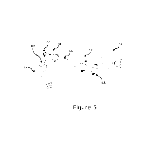
Referring additionally to Figure 5, the aircraft landing gear assembly 50 has
a first landing
gear element movably coupled relative to a second landing gear element to
pivot about a
pivot axis between a first condition and a second condition.
CA 03221503 2023- 12- 5
WO 2023/274917 11
PCT/EP2022/067492
In the illustrated embodiment the first landing gear element 60 is the upper
lock link
member 60 of the lock link 58 and the second landing gear element is a cardan
pin 62,
via which the upper lock link member 60 is movably coupled to the outer
cylinder 52. The
upper lock link member 60 is pivotally coupled to the cardan pin 62 via a
pivot pin 64 to
enable the lock link 58 to fold and unfold between the locked and passive
conditions.
A leaf spring 66 is provided to bias the lock link 58 to assume the locked
condition in a
similar manner to the spring shown in Figures 3a and 3b. However, in this
embodiment
the leaf spring 66 is mounted to the upper lock link member 60 and arranged to
act on
the cardan pin 62.
More specifically, a first end of the leaf spring 66 is mounted in a static
fitting 68 such that
the first end generally cannot move relative to the upper lock link member 60.
The static
fitting can for example define clamping surfaces drawn together by mechanical
fixings
such as screws or bolts to hold the first end of the spring 66. The first end
of the spring
66 can be outwardly tapered to define a wedge to inhibit the spring 66 being
drawn from
the static fitting 68 in use.
A second end of the spring 66 is provided with an end fitting 70 which defines
a cam
follower arranged to contact the head of the cardan pin 62 as the landing gear
assembly
moves between deployed and retracted conditions. The end fitting 70 can be
mechanically
coupled to the spring 66 by a nut and bolt arrangement or the like to provide
a removable
coupling, or can for example be bonded to the spring 66.
In this embodiment the cam follower is defined by a roller 72 mounted at the
free end of
the end fitting 70. The roller 72 can be formed of any conventional roller
materials,
preferably a material that is galvanically compatible with the cardan pin 62;
in one
example, the cardan pin 62 can be formed from stainless steel with a suitable
surface
coating and the roller can be formed from stainless steel.
In other embodiments, an end fitting can define a smooth surface to serve as a
cam
follower. In such embodiments, the end fitting or just the smooth surface of
it can be
formed of any suitable material that is galvanically compatible with the
cardan pin 62; in
one example, the cardan pin 62 can be formed from stainless steel with a
suitable surface
coating and the smooth surface can be formed from stainless steel.
Referring additionally to Figure 6, the head of the cardan pin 62 defines a
cam surface 74.
The cam surface 74 is spatially fixed with respect to the pivot axis PA in the
sense that the
CA 03221503 2023- 12- 5
WO 2023/274917 12
PCT/EP2022/067492
radial offset RO between a particular point on the cam surface 74 and the
pivot axis PA
remains constant as the landing gear moves between deployed and stowed
conditions.
The leaf spring 66 is coupled to the upper lock link member 60 to move with
the upper
lock link member 60. The mounting orientation of the leaf spring 66 is such
that the
longitudinal axis of the leaf spring 66 is skew with respect to the
longitudinal axis of the
upper lock link member 60 such that the roller 72 is positioned in contact
with the cam
surface 74 at the head of the cardan pin 62.
Thus, as the upper lock link member 60 pivots about the pivot axis PA relative
to the
cardan pin 62 due to the landing gear moving from the deployed condition to
the stowed
condition, the roller 72 moves from a first region R1 of the cam surface 74 to
a third region
R3 of the cam surface 74 via a second region R2 of the cam surface 74, bending
the leaf
spring 66 as it moves along the first region R1 towards the second region R2.
Referring additionally to Figure 7, the cam surface 74 is shaped such that a
radial offset
distance RO between the pivot axis PA and the cam surface 74 increases between
the first
region R1 and the second region R2 to define a first gradient, shown between
points 1 and
2 in the solid line plot of leaf spring load vs. landing gear retraction
angle, which can refer
to the angle of the main strut relative to the fully deployed orientation. The
radial offset
distance RO varies between the second region R2 and the third region R3 of the
cam
surface to define a second gradient, shown between point 2 and point 3 in
Figure 7. The
second gradient is less steep than the first gradient.
Thus, the spring load is not greater when the landing gear is stowed in
comparison to an
operational condition in which the spring is arranged to urge the lock link to
assume the
locked, over centre condition. In this manner, spring fatigue can be reduced,
thereby
increasing the lifespan of the leaf spring and reducing maintenance
requirements. In
contrast, in known spring arrangements, spring load can continuously increase
with
landing gear retraction angle, as shown by the dashed line in Figure 7.
With the cam profile, it is possible to easily increase the effective arm
where necessary
and to relieve the spring deformation when the gear is retracted, in the
stowed condition.
This has the potential to improve fatigue life and stress corrosion
conditions. The cam
surface can for example be configured such that the radial offset decreases
between the
second region R2 and the third region R3 to reduce the spring load when the
landing gear
is stowed, as illustrated in the dot-dash line in Figure 7.
CA 03221503 2023- 12- 5
WO 2023/274917 13
PCT/EP2022/067492
When the landing gear moves from the stowed condition to the deployed
condition, the
upper lock link member 60 rotates in relation to the cardan pin 62. This
relative rotational
movement is used to lock the mechanism by the addition of a moment load using
existing
landing gear components assisted by a cam surface, a roller and a spring. This
concept
takes advantage of the energy stored in the spring as it retracts, by the
roller, over a cam
surface machined on the top of cardan pin, generating a down locking moment.
It also
has the ability to tailor the spring deflection (and hence load) throughout
deployment to
more closely match a given down-locking requirements curve. In terms of
performance,
a leaf spring is able to achieve high levels of load with small deformations,
especially when
compared to a coil spring.
In order to have the landing gear positioned and locked, there is a
performance
requirement that the down locking mechanism must meet. This requirement is
defined as
a moment that the mechanism must generate when the upper lock link member 60
rotates
in relation to the cardan pin 62. This moment, in combination with the
effective arms,
defines the required spring force. Once the spring force is defined, it is
possible to define
the contact stress between the cam 74 and the roller 72. The stress is
influenced by the
minimum radius of the cam shape which also works as a design restriction. The
leaf spring
66 has a limit of work in terms of deflection that is defined by the maximum
stress
allowable and limit of fatigue for the material. The spring geometry, can be
adjusted to
suit, however there is a limitation of space and clearances for the
installation that has to
be considered alongside the kinematic mechanism.
As best shown in Figure 6, a region of the end fitting 70 between the first
and second end
regions can define a relatively narrow waist region WR, where an outer surface
of the end
fitting is offset from a central axis of the end fitting less than a distance
by which the
contact surface of the cam follower is offset from the central axis. This can
reduce the
likelihood of the fouling between the end fitting 70 and the cardan pin 62 as
the roller 72
moves along the cam surface 74.
Referring now to Figure 8, an aircraft landing gear assembly 80 according to a
further
embodiment of the invention is shown. The aircraft landing gear assembly 80 is
identical
to the aircraft landing gear assembly 50 of Figure 4, except that it has a
pair of spring and
cam arrangements. More specifically, the aircraft landing gear assembly 80
comprises a
second leaf spring 82 and a second cam surface 84. The leaf springs 66, 82 are
mounted
in parallel on the upper lock link element 60 and the cam surfaces 74, 84 are
located in
parallel, so as to define a symmetrical arrangement on either side of the
longitudinal axis
of the upper lock link element 60.
CA 03221503 2023- 12- 5
WO 2023/274917 14
PCT/EP2022/067492
While the illustrated embodiments include a down-lock spring 66 mounted on the
upper
lock link member 60 and arranged to act on a cam surface 74 defined by the
head of the
cardan pin 62, in other embodiments a down-lock spring and cam arrangement
according
to the invention can be configured in different manners. For example,
referring to Figures
9 and 10, a portion of a landing gear assembly according to a further
embodiment is shown
generally at 90. The landing gear assembly 90 is similar to the landing gear
assembly 50
of Figure 4 and for brevity the following description will focus on the
differences. In this
embodiment, the down-lock spring 92 is mounted on the upper lock link member
94 in an
opposite direction so as to act upon a cam surface 96 defined by an end region
of the
lower lock link member 98. A plurality of springs can be provided as per
Figure 8.
In other embodiments, a leaf spring and cam arrangement according to the
invention can
be configured between different first and second elements, so as to serve
other than a
down-lock spring, such as an upper lock or 'up-lock' mechanism for holding a
landing gear
in a stowed condition, an assembly to assist the landing gear in
retraction/extension or
the steering mechanism, or an assembly forming part of a landing gear bay
door.
In any embodiment, the leaf spring can be formed from any suitable material,
such as a
metallic material such as spring steel, or a composite material such as fibre
reinforced
polymer composite.
It should be noted that the above-mentioned embodiments illustrate rather than
limit the
invention, and that those skilled in the art will be capable of designing many
alternative
embodiments without departing from the scope of the invention as defined by
the
appended claims. In the claims, any reference signs placed in parenthesis
shall not be
construed as limiting the claims. The word "comprising" does not exclude the
presence of
elements or steps other than those listed in any claim or the specification as
a whole. The
singular reference of an element does not exclude the plural reference of such
elements
and vice-versa. Parts of the invention can be implemented by means of hardware
comprising several distinct elements. In a device claim enumerating several
parts, several
of these parts can be embodied by one and the same item of hardware. The mere
fact
that certain measures are recited in mutually different dependent claims does
not indicate
that a combination of these measures cannot be used to advantage.
CA 03221503 2023- 12- 5