Note: Descriptions are shown in the official language in which they were submitted.
WO 2022/256944
PCT/CA2022/050937
HYPOTROCHOID POSITIVE-DISPLACEMENT MACHINE
TECHNICAL FIELD
[0001] Internal gear fluid transfer devices.
SUMMARY
[0002] A displacement device may have a housing, an inner rotor
and an outer rotor
The inner rotor may be fixed for rotation relative to the housing about a
first axis, and the
outer rotor fixed for rotation relative to the housing about a second axis
parallel to and offset
from the first axis. The inner rotor has radially outward-facing projections,
and the outer
rotor radially inward-facing projections configured to mesh with the radially
outward facing
projections of the inner rotor. The inner rotor, outer rotor and housing may
collectively form
a set of components arranged for relative motion in planes perpendicular to
the first axis, the
set of components defining axially facing surfaces including at least one
surface pairing
arranged to form an interface between a first axially facing surface and a
second axially
facing surface of the at least one surface pairing, the first axially facing
surface and the
second axially facing surface being defined by different components of the
set, the first
axially facing surface of the at least one surface pairing being configured to
shape or be
shaped by, or both, the second axially facing surface of the at least one
surface pairing.
[0003] In various embodiments, there may be included any one or
more of the
following features: the radially inward-facing projections of the outer rotor
may seal against
the radially outward-facing projections of the inner rotor at a Bottom Dead
Center zone
including Bottom Dead Center (BDC) of the displacement device, and seal
against troughs
between the radially outward-facing projections of the inner rotor at a Top
Dead Center zone
including Top Dead Center (TDC) of the displacement device, the BDC and TDC
sealing
zones separating the displacement device into higher and lower pressure
regions. The
radially inward-facing projections of the outer rotor, in combination with the
sealing of the
radially inward-facing projections of the outer rotor against the inner rotor,
may be
configured to produce substantially equal and opposite torques on the outer
rotor as a result
of their similar surface areas exposed to the higher pressure fluid at TDC and
BDC. Two
1
CA 03221553 2023- 12- 5
WO 2022/256944
PCT/CA2022/050937
consecutive radially inward-facing projections of the radially inward-facing
projections of
the outer rotor and two consecutive zones between the radially outward-facing
projections of
the inner rotor may be respectively shaped such that a seal is maintained
between the inner
and outer rotor in a chamber past TDC to provide an internal expansion of
compressed fluid
that passes through TDC. Two consecutive radially outward-facing projections
of the
radially outward-facing projections of the inner rotor may be respectively
shaped such that a
seal is maintained between the inner and outer rotors in a chamber past BDC to
provide an
internal compression of fluid that passes through BDC. The at least one
surface pairing may
include a first housing surface pairing comprising a first surface of the
housing and an outer
surface of one of the inner rotor and the outer rotor arranged to form a first
housing interface,
the first surface of the housing being configured to shape or be shaped by, or
both, the outer
surface of the one of the inner rotor and the outer rotor. The housing may
include a port
plate, and the at least one surface pairing may include a port plate surface
pairing comprising
a surface of the port plate and an outer surface of one of the inner rotor and
the outer rotor
being arranged to form a port plate interface, the surface of the port plate
being configured to
shape or be shaped by, or both, the outer surface of the one of the inner
rotor and the outer
rotor. The outer surface of the one of the inner rotor and the outer rotor may
be defined by an
endplate of the one of the inner rotor and the outer rotor. The outer surface
of the one of the
inner rotor and the outer rotor may be an outer surface of the outer rotor.
There may also be
port plate interface fluid supply channels configured to supply fluid under
pressure to the
port plate interface for debris removal. There may also be proud port plate
interface elements
on the surface of the port plate or on the outer surface of the one of the
inner rotor and the
outer rotor, the proud port plate interface elements being arranged to shape
the outer surface
of the one of the inner rotor and the outer rotor in the case that the proud
port plate interface
elements are on the surface of the port plate, and the proud port plate
interface elements
being arranged to shape the surface of the port plate in the event that the
proud port plate
interface elements are on the outer surface of the one of the inner rotor and
the outer rotor.
The proud port plate interface elements may have spiral-shaped port plate
interface shaping
edges, the port plate interface shaping edges being oriented to push shaping
debris from the
port plate interface in a radially outward direction when the axially facing
surfaces of the
2
CA 03221553 2023- 12- 5
WO 2022/256944
PCT/CA2022/050937
port plate surface pairing move in an expected direction of relative motion in
use of the
displacement device. The outer surface of the one of the inner rotor and the
outer rotor may
have the proud port plate interface elements. The surface of the port plate
may comprise a
plastic material over a metal backing plate_ There may be an actuator for
positioning the
surface of the port plate in contact with or close to the surface of the one
of the inner rotor
and the outer rotor. The actuator may include a chamber in the housing
configured to receive
pressurized fluid, the port plate being in contact with the chamber to act as
a piston. There
may be a purge valve connecting the chamber to an inlet of the machine. There
may be a
biasing element biasing the port plate away from the outer surface of the one
of the inner
rotor and the outer rotor against a stop. The at least one surface pairing may
include a first
rotor surface pairing comprising a first surface of the inner rotor and a
first surface of the
outer rotor arranged to form a first rotor interface, the first surface of the
outer rotor being
configured to shape or be shaped by, or both, the first surface of the inner
rotor. The first
surface of the outer rotor may be defined by an endplate of the outer rotor.
There may be
first rotor interface fluid supply channels configured to supply fluid under
pressure to the
first rotor interface for debris removal. There may be proud first rotor
interface elements on
the first surface of the inner rotor or on the first surface of the outer
rotor, the proud first
rotor interface elements being arranged to shape the first surface of the
inner rotor in the case
that the proud first rotor interface elements are on the first surface of the
outer rotor, and the
proud first rotor interface elements being arranged to shape the first surface
of the outer rotor
in the event that the proud first rotor interface elements are on the first
surface of the inner
rotor. The proud first rotor interface elements may have spiral-shaped first
rotor interface
shaping edges, the first rotor interface shaping edges being oriented to push
shaping debris
from the first rotor interface in a radially outward direction when the
surfaces of the first
rotor surface pairing move in an expected direction of relative motion in use
of the
displacement device. The first surface of the outer rotor may have the proud
first rotor
interface elements. The at least one surface pairing may include a second
rotor surface
pairing comprising a second surface of the inner rotor and a second surface of
the outer rotor
arranged to form a second rotor interface, the second surface of the outer
rotor being
configured to shape or be shaped by, or both, the second surface of the inner
rotor. The
3
CA 03221553 2023- 12- 5
WO 2022/256944
PCT/CA2022/050937
second surface of the outer rotor may be defined by a second endplate of the
outer rotor. The
second rotor interface fluid supply channels may be configured to supply fluid
under
pressure to the second rotor interface for debris removal. There may be proud
second rotor
interface elements on the second surface of the inner rotor or on the second
surface of the
outer rotor, the proud second rotor interface elements being arranged to shape
the second
surface of the inner rotor in the case that the proud second rotor interface
elements are on the
second surface of the outer rotor, and the proud second rotor interface
elements being
arranged to shape the second surface of the outer rotor in the event that the
proud second
rotor interface elements are on the second surface of the inner rotor. The
proud second rotor
interface elements may have spiral-shaped second rotor interface shaping
edges, the second
rotor interface shaping edges being oriented to push shaping debris from the
second rotor
interface in a radially outward direction when the surfaces of the second
rotor surface pairing
move in an expected direction of relative motion in use of the displacement
device. The
second surface of the outer rotor may have the proud second rotor interface
elements. The at
least one surface pairing may include a housing surface pairing comprising an
axially-facing
housing surface and a corresponding axially-facing surface of at least one of
the inner rotor
or the outer rotor arranged to form a housing interface, the axially-facing
housing surface
being configured to shape or be shaped by, or both, the corresponding axially
facing surface.
There may be interface fluid supply channels configured to supply fluid under
pressure to the
housing interface for debris removal_ There may be proud housing interface
elements on the
axially-facing housing surface or on the corresponding axially-facing surface,
the proud
housing interface elements being arranged to shape the corresponding axially-
facing surface
in the case that the proud housing interface elements are on the axially-
facing housing
surface, and the proud housing interface elements being arranged to shape the
axially-facing
housing surface in the event that the proud second rotor interface elements
are on the
corresponding axially-facing surface. The proud housing interface elements may
have spiral-
shaped housing interface shaping edges, the second housing shaping edges being
oriented to
push shaping debris from the housing interface in a radially outward direction
when the
surfaces of the housing surface pairing move in an expected direction of
relative motion in
use of the displacement device. The axially-facing surface of the at least one
of the inner
4
CA 03221553 2023- 12- 5
WO 2022/256944
PCT/CA2022/050937
rotor or the outer rotor may have the proud second rotor interface elements.
There may be a
fluid supply channel arrangement, which may include fluid supply channels
supplying fluid
to any one or more of the interfaces described above for debris removal. The
fluid supply
channel arrangement may include for example a flow passage through a shaft of
the in
rotor. Fluid supply channels to different interfaces may be connected together
or separate,
and if separate may supply the same or a different fluid. The fluid may be the
same as or
different from a working fluid of the displacement device. The outer rotor may
be configured
to provide a clearance between roots of the inward-facing projections of the
outer rotor and
tips of the outward-facing projections of the inner rotor, the clearance
selected to
accommodate ice buildup between the projections of the outer rotor. There may
be mounting
features to mount the displacement device on an external surface or structure
such that the
first axis has a nonvertical, non-horizontal orientation in which a discharge
port of the
displacement device is located substantially at a lowest part of an active
volume of the
displacement device. The orientation of the first axis may be between 1 degree
and 45
degrees from vertical. The inner rotor may comprise a shapable material, for
example a
machinable or abradable material. The inner rotor may comprise
polytetrafluoroethylene
(PTFE). There may be a screen arranged to contact a fluid flow into the
displacement device,
the screen arranged to have a screen temperature that cools more quickly than
fluid-facing
surfaces of the outer rotor when the displacement device is shut down after
use. The screen
may be thermally connected to a heat sink exposed to an ambient temperature_
The radially
inward-facing projections may have leading and trailing portions configured to
contact the
radially outward-facing projections of the inner rotor between the sealing
zones. There may
be flow channels arranged to prevent the formation of a sealed secondary
chamber between
the radially outward-facing projections of the inner rotor and the radially
inward-facing
projections of the outer rotor at or near Top Dead Center (TDC). The trailing
portions of the
radially inward-facing outer rotor projections may provide relative rotational
positioning of
the outer rotor and inner rotor and may provide a contact ratio between the
rotors in a
direction of rotation of 1 or greater. The leading portions of the radially
inward-facing outer
rotor projections may provide relative rotational positioning of the outer
rotor and inner rotor
and may provide a contact ratio between the rotors in a direction of rotation
of 1 or greater.
CA 03221553 2023- 12- 5
WO 2022/256944
PCT/CA2022/050937
The radially outward-facing projections of the inner rotor may have shapable
sealing zone
surfaces comprising a shapable material, and portions of the inner rotor
outward-facing
projections providing rotational positioning relative to the outer rotor may
also comprise the
shapable material_ Each of the axially facing surfaces of the at least one
surface pairing may
comprise an abradable material and may be configured to shape the other of the
axially
facing surfaces of the at least one surface pairing.
[0004] A displacement device may have a housing, an inner rotor
and an outer rotor.
The inner rotor may have a number of outward-facing projections, and the outer
rotor may
have a number of inward-facing projections. The inner rotor may be fixed for
rotation
relative to the housing about a first axis, and the outer rotor fixed for
rotation relative to the
housing about a second axis parallel to and offset from the first axis. The
number of inward-
facing projections of the outer rotor may be, for example, greater by one than
the number of
outward-facing projections of the inner rotor. The outward-facing projections
of the inner
rotor and the inward-facing projections of the outer rotor may intermesh, the
outer rotor and
the inner rotor being configured to rotate at a relative ratio of rotation
speeds defined by a
ratio of the number of inner rotor projections to the number of outer rotor
projections. The
inward-facing projections of the outer rotor may have inward-most tips
defining
hypotrochoid paths relative to the inner rotor, the inner rotor comprising tip
sealing zones at
tips of the outward-facing projections and trough sealing zones at troughs
between the
outward-facing projections, the tip sealing zones and the trough sealing zones
being arranged
to seal against the inward-most tips of the projections of the outer rotor as
the inward-most
tips trace the hypotrochoid paths.
[0005] In various embodiments, there may be included any one or
more of the
following features: the tip sealing zones may occur at a Bottom Dead Center
zone including
Bottom Dead Center (BDC) of the displacement device, and trough sealing zones
may occur
at a Top Dead Center zone including Top Dead Center (TDC) of the displacement
device,
the BDC and TDC sealing zones separating the displacement device into higher
and lower
pressure regions. The radially inward-facing projections of the outer rotor,
in combination
with the sealing of the radially inward-facing projections of the outer rotor
against the inner
rotor, may be configured to produce substantially equal and opposite torques
on the outer
6
CA 03221553 2023- 12- 5
WO 2022/256944
PCT/CA2022/050937
rotor as a result of their similar surface areas exposed to higher pressure
fluid at TDC and
BDC. Two consecutive radially inward-facing projections of the radially inward-
facing
projections of the outer rotor and two consecutive zones between the radially
outward-facing
projections of the inner rotor may be respectively shaped such that a seal is
maintained
between the inner and outer rotor in a chamber past TDC to provide an internal
expansion of
compressed fluid that passes through TDC. Two consecutive radially outward-
facing
projections of the radially outward-facing projections of the inner rotor may
be respectively
shaped such that a seal is maintained between the inner and outer rotors in a
chamber past
BDC to provide an internal compression of fluid that passes through BDC. A
screen may be
arranged to contact a fluid flow into the displacement device, the screen
arranged to have a
screen temperature that cools more quickly than fluid-facing surfaces of the
outer rotor when
the displacement device is shut down after use. The screen may be thermally
connected to a
heat sink exposed to an ambient temperature. The sealing zones at the tips of
the outward-
facing projections or the sealing zones at the troughs between the outward-
facing projections
or both may be configured with the inward-most tips of the outer rotor to be
shaped by the
inward-most tips of the outer rotor. A first inward-facing projection of the
outer rotor may
have a first tip geometry different than a second tip geometry of a second
inward-facing
projection of the outer rotor, the first tip geometry having a sharper angle
of incidence with
the tips of the outward-facing projections of the inner rotor in a direction
of relative motion
at bottom Dead Center (BDC) and the second tip geometry having a sharper angle
of
incidence at the troughs between the outward-facing projections of the inner
rotor in a
direction of relative motion at Top Dead Center (TDC). The first tip and
second tip may be
arranged so that the first tip and the second tip trace a common hypotrochoid
path relative to
the inner rotor. The inward-facing projections of the outer rotor may include
a plural number
of sets of projections, the projections of each set having a respective common
geometry, and
the outer rotor projection number being a multiple of the plural number of the
sets. The
inward-most tips of the inward-facing projections of the outer rotor may be
made of a harder
material than the tip sealing zones and than the trough sealing zones and the
inward-most
tips of the inward-facing projections of the outer rotor may be configured to
shape the tip
sealing zones and the trough sealing zones in operation of the displacement
device. The
7
CA 03221553 2023- 12- 5
WO 2022/256944
PCT/CA2022/050937
inward-facing projections of the outer rotor may be tapered to sharp edges at
the inward-
most tips. The inward-most tips of the outer rotor may be configured with
rounded surfaces.
Each point on the rounded surface may still define a hypotrochoid path and the
sealing
surfaces of the inner rotor may still be designed to seal against the rounded
surfaces of the
outer rotor tips, and the tips of the outer rotor fins, depending on the
embodiment, may still
shape, including e.g. wear-in, the inner rotor sealing surfaces. The tip
sealing zones or the
trough sealing zones or both may comprise radially movable seals. The radially
movable
seals may be radially movable at a first temperature and configured to become
radially fixed
or tighter fitting in their grooves at a second temperature. The inward-facing
outer rotor
projections may have leading and trailing portions configured to contact the
outward-facing
projections of the inner rotor between the tip sealing zones and the trough
sealing zones.
There may be flow channels arranged to prevent the formation of a sealed
secondary
chamber between the outward-facing projections of the inner rotor and the
inward-facing
projections of the outer rotor at or near Top Dead Center (TDC). For the
purpose of this
disclosure, a chamber is defined as a volume which is formed by contact or
near contact
interactions, for example a pair of such interactions, between two or more
elements, for
example between the inner rotor and the outer rotor. The trailing portions of
the inward-
facing outer rotor projections may provide relative rotational positioning of
the outer rotor
and inner rotor and provide a contact ratio between the rotors in a direction
of rotation of one
or greater_ The leading portions of the inward-facing outer rotor projections
may provide
relative rotational positioning of the outer rotor and inner rotor and provide
a contact ratio
between the rotors in a direction of rotation of one or greater. A trough of
the troughs
between the outward-facing projections may have a shape such that a sealed
chamber is
maintained past Top Dead Center (TDC) to provide an internal expansion of
fluid that passes
through TDC. Other troughs, for example all of the troughs between the outward-
facing
projections, may be similarly shaped. An inner rotor projection of the outward-
facing
projections may have a shape such that a sealed chamber is maintained past
Bottom Dead
Center (BDC) to provide an internal compression of fluid that passes through
BDC. Other
projections, for example all of the outward-facing projections, may be
similarly shaped. The
tip sealing zones, the trough sealing zones, or both may comprise a shapable
material,
8
CA 03221553 2023- 12- 5
WO 2022/256944
PCT/CA2022/050937
portions of the inner rotor outward-facing projections providing rotational
positioning
relative to the outer rotor also comprising the shapable material.
[0006] A method of running-in a displacement device may include
providing a
displacement device comprising an inner rotor and an outer rotor, the inner
rotor having
radially movable seals configured to seal against radially innermost tips of
inward-facing
projections of the outer rotor, the radially movable seals being radially
movable or fixed
depending on a temperature of the seals. The radially movable seals may be
located at tips of
outward-facing projections of the inner rotor or at troughs between the
outward-facing
projections of the inner rotor or both, The method may further include
operating the
displacement device at a first temperature, allowing the radially movable
seals to radially
advance, when the displacement device is operated at the first temperature, to
respective top-
out positions in which they contact the radially innermost tips of the inward-
facing
projections of the outer rotor, and, for example subsequently, operating the
displacement
device at a second temperature, the radially moveable seals being fixed in the
respective top-
out positions when the displacement device is operated at the second
temperature.
[0007] In various embodiments, there may be included any one or
more of the
following features: the radial advancement of the radially moveable seals,
when the
displacement device is operated at the first temperature, may occur due to
centrifugal force.
The radially moveable seals may be biased radially inward. For example, the
radially
moveable seals may be biased radially inward by springs_ The seals may
alternatively be
biased radially outward, e.g. by springs, for example such that radial
advancement occurs
under the biasing force. The seals may be disposed within grooves, the
radially moveable
seals being radially moveable at the first temperature and fixed or tighter in
their grooves at
the second temperature due to differential thermal expansion of the seals
relative to a
material defining the grooves. The seals being fixed may, for example, allow a
position to be
set that will establish a small gap. The seals being tighter may, for example,
reduce leak
paths around the seals within the grooves.
[0008] A further method of running-in a displacement device may
include providing
a displacement device, the displacement device comprising a housing and an
inner rotor
having radially outward-facing projections, the inner rotor being fixed for
rotation relative to
9
CA 03221553 2023- 12- 5
WO 2022/256944
PCT/CA2022/050937
the housing about a first axis, and an outer rotor having radially inward-
facing projections
configured to mesh with the radially outward-facing projections of the inner
rotor, the outer
rotor being fixed for rotation relative to the housing about a second axis
parallel to and offset
from the first axis, and the inner rotor having a first axial facing surface
and a second axial
facing surface. The method may also include operating the displacement device
under
conditions such that the first axial facing surface interferes with a first
corresponding axial
facing surface of the outer rotor or the housing to cause the first
corresponding axial facing
surface to shape the first axial facing surface, or operating the displacement
device under
conditions such that the second axial facing surface interferes with a second
corresponding
axial facing surface of the outer rotor or the housing to cause the second
corresponding axial
facing surface to shape the second axial facing surface, or under conditions
where both will
occur. Subsequently, the displacement device may be operated under conditions
where at
least some of the above-mentioned interference does not occur.
[0009] In various embodiments, there may be included any one or
more of the
following features: the inner rotor may be constructed to cause the above-
mentioned
interference when the displacement device is operated as constructed, and the
subsequent
operation without interference may be due to the shaping of the inner rotor
when the
displacement device is operated as constructed. The conditions under which the
interference
occurs may be conditions in which the inner rotor has a first temperature, and
the inner rotor
may have a second temperature different from the first temperature during the
subsequent
operation without interference.
[0010] A still further method of running-in a displacement
device may include
providing a displacement device, the displacement device comprising a housing
and an inner
rotor having radially outward-facing projections, the inner rotor being fixed
for rotation
relative to the housing about a first axis, and an outer rotor having radially
inward-facing
projections configured to mesh with the radially outward-facing projections of
the inner
rotor, the outer rotor being fixed for rotation relative to the housing about
a second axis
parallel to and offset from the first axis, and the housing including a port
plate having a port
plate axially facing surface facing a corresponding axially facing surface of
the inner rotor or
the outer rotor. The method may also include operating the displacement device
under
CA 03221553 2023- 12- 5
WO 2022/256944
PCT/CA2022/050937
conditions such that the port plate axial facing surface interferes with the
corresponding axial
facing surface of the inner rotor or the outer rotor to cause the
corresponding axial facing
surface to shape the port plate axial facing surface, and subsequently
operating the
displacement device without interference between the port plate axial facing
surface and the
corresponding axial facing surface.
[0011] In various embodiments, there may be included any one or
more of the
following features: the port plate may be constructed to cause interference
when the
displacement device is operated as constructed, and the subsequent operation
without
interference may be due to the shaping of the port plate when the displacement
device is
operated as constructed. The conditions such that the port plate axial facing
surface interferes
with the corresponding axial facing surface of the inner rotor or the outer
rotor may be
conditions in which the port plate has a first temperature, and the port plate
may have a
second temperature different from the first temperature during the subsequent
operation
without interference.
A method of clearing ice from a displacement device may be applied to
displacement device
having a housing, an inner rotor having radially outward-facing projections,
the inner rotor
being fixed for rotation relative to the housing about a first axis, an outer
rotor having
radially inward-facing projections configured to mesh with the radially
outward-facing
projections of the inner rotor, the outer rotor being fixed for rotation
relative to the housing
about a second axis parallel to and offset from the first axis, or to any
displacement device as
described above. The method includes the steps of operating the displacement
device, an
internal temperature of the displacement device during operation being greater
than 0
degrees Celsius, ceasing to operate the displacement device, monitoring the
internal
temperature of the displacement device over a cool-down period after ceasing
to operate the
displacement device as the internal temperature of the displacement device
cools towards an
ambient temperature less than 0 degrees Celsius, on detecting that the
internal temperature of
the displacement device is approaching 0 degrees Celsius, rotating the
displacement device
to cause water in the displacement device to be displaced from the
displacement device, for
example by spinning the rotors of the displacement device to cause condensed
water in the
displacement device to be centrifuged away from the rotors of the displacement
device. The
11
CA 03221553 2023- 12- 5
WO 2022/256944
PCT/CA2022/050937
detection that the internal temperature of the displacement device is
approaching 0 degrees
Celsius may be implemented by for example detecting that the internal
temperature has
reached a threshold temperature, or for example detecting that a temperature
trend in the
internal temperature will lead to 0 degrees Celsius or a different
ternperature threshold within
a time threshold. The displacement device may include a screen arranged to
filter fluid flow
into the displacement device, the screen arranged to have a screen temperature
lower than the
device temperature of the displacement device during the cool-down period.
[0012] These and other aspects of the device and method are set
out in the claims.
BRIEF DESCRIPTION OF THE FIGURES
[0013] Embodiments will now be described with reference to the
figures, in which
like reference characters denote like elements, by way of example, and in
which:
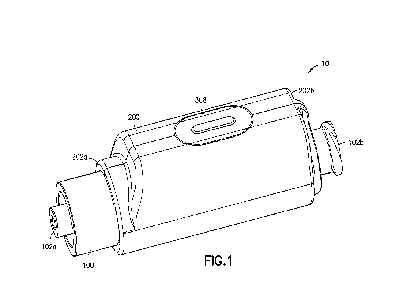
[0014] Fig. 1 is an exploded isometric view of an exemplary
fluid transfer device
showing a housing, port plate, outer rotor and inner rotor.
[0015] Fig. 2 is a top view of the port plate of the exemplary
fluid transfer device of
Fig. 1.
[0016] Fig. 3 is a top view of the exemplary fluid transfer
device of Fig. 1 showing
the inner and outer rotor as well as the housing.
[0017] Fig. 4 is a bottom view of the housing of the exemplary
fluid transfer device
of Fig. 1 showing intake and exhaust ports, and port plate adjustment screws_
[0018] Fig. 5 is an isometric view of an assembly of components
of a further
exemplary fluid transfer device including an inner rotor with radially movable
apex seals,
and outer rotor endplate.
[0019] Fig. 6 is an isometric section view of the further
exemplary fluid transfer
device of Fig. 5 showing an input shaft, inner rotor, outer rotor, and
endplate.
[0020] Fig. 7 is an isometric view of the further exemplary
fluid transfer device of
Fig. 5 showing a port plate, intake port and exhaust port.
[0021] Fig. 8 is a section view of another exemplary fluid
transfer device, showing
the inner rotor, outer rotor, input shaft, port plate, and housing.
12
CA 03221553 2023- 12- 5
WO 2022/256944
PCT/CA2022/050937
[0022] Fig. 9 is a flow chart illustrating a method of running
in a fluid transfer
device.
[0023] Fig. 10 is a schematic drawing of a hypotrochoid path
traced by the ends of
the outer rotor lobes relative to the inner rotor_
[0024] Fig. 11 is a top view showing the schematic drawing of
the hypotrochoid path
shown in Fig. 10 as traced by the tips of the outer rotor projections
overlayed over the inner
and outer rotor of an exemplary machine.
[0025] Fig. 12 is a top view of an exemplary machine showing a
driving surface of
an inner rotor and a corresponding driven surface of an outer rotor.
[0026] Fig. 13 is a top view of the inner rotor and outer rotor
of the exemplary
machine of Fig. 5, showing the hypotrochoid path as traced by the tips of the
outer rotor
proj ections.
[0027] Fig. 14 is an isometric view of the inner rotor and
outer rotor shown in Fig.
13.
[0028] Fig. 15 is a top view of an inner rotor and an outer
rotor of an exemplary
machine, the inner rotor having seven outward-facing projections and the outer
rotor having
eight inward-facing projections.
[0029] Fig. 16 is a top view of an inner rotor and an outer
rotor of an exemplary
machine, the inner rotor having eleven outward-facing projections and the
outer rotor having
twelve inward-facing projections.
[0030] Fig. 17 is a top view of an exemplary machine which has
an inner rotor
having nine outward-facing projections and an outer rotor having ten inward-
facing
proj ections.
[0031] Fig. 18 is a close-up top view of inner and outer
projections of the machine of
Fig. 17 meeting near Bottom Dead Center (BDC) showing a detailed view of the
sealing/shaping interaction between the inner and outer rotor.
[0032] Fig. 19 is a close up top view of a shaping edge of an
outer rotor projection.
[0033] Fig. 20 is a view of a projection of an outer rotor in
shaping contact with an
inner rotor near Top Dead Center (IDC).
13
CA 03221553 2023- 12- 5
WO 2022/256944
PCT/CA2022/050937
[0034] Fig. 21 is atop view near BDC of inward-facing
projections of an inner rotor
in an exemplary machine showing two different types of shaping edges on
alternating
projections of the outer rotor.
[0035] Fig_ 22 is a top view of the exemplary machine of Fig_
21, which has an inner
rotor having nine outward-facing projections and an outer rotor having ten
inward-facing
projections, with adjacent outer rotor projections having different shaping
edges.
[0036] Fig. 23 is a top view close-up showing the shaping edge
of an outer rotor
projection of the embodiment of Fig. 21.
[0037] Fig. 24 is a top view overlay of two different outer
rotor shaping edges of
another exemplary machine on top of each other to show that the tips seal at
the same
location.
[0038] Fig. 25 is an isometric exploded view of the exemplary
machine of Fig. 22.
[0039] Fig. 26 is an isometric view of an endplate of the
exemplary machine of Fig.
25 showing shaping features.
[0040] Fig. 27 is an isometric exploded view of the exemplary
machine of Fig. 22
showing a different isometric perspective than Fig. 25.
[0041] Fig. 28 is a first isometric view of an outer rotor of
the exemplary machine of
Fig. 22 showing non-sealing portions which provide flow channels which prevent
secondary
chambers from sealing as well as shaping features on an axial face of the
outer rotor.
[0042] Fig. 29 is an isometric exploded view of selected
components of the
exemplary machine of Fig. 22.
[0043] Fig. 30 is a bottom view of the outer rotor of the
exemplary machine of Fig.
22 showing shaping features on an axial face of the outer rotor.
[0044] Fig. 31 is a second isometric view of the outer rotor of
the exemplary machine
of Fig. 22 showing shaping features on an axial face of the outer rotor.
[0045] Fig. 32 is an isometric view showing an assembly of an
outer rotor end plane
and an inner rotor of the exemplary machine of Fig. 29 with shaping features
shown on the
outer rotor endplate.
[0046] Fig. 33 is a top view of an outer rotor showing shaping
features in the radial
and axial direction.
14
CA 03221553 2023- 12- 5
WO 2022/256944
PCT/CA2022/050937
[0047] Fig. 34 is a top view of an outer rotor having an
alternate shaping feature
design to the one shown in Fig. 33, as well as a view of non-sealing portions
which provide
fluid channels.
[0048] Fig_ 35 is a top view of an outer rotor of an exemplary
machine which has an
inner rotor having nine outward-facing projections and the outer rotor having
ten inward-
facing projections, showing axial shaping features.
[0049] Fig. 36 is a section view of an exemplary machine which
has an inner rotor
having nine outward-facing projections and the outer rotor having ten inward-
facing
projections, showing ice-clearing components.
[0050]
[0051] Fig. 37 is a schematic drawing showing a device
including a mesh screen for
reducing ice build-up in cold operating conditions.
[0052] Fig. 38 is a section view of an exemplary machine
showing an inner rotor
having nine outward-facing projections and an outer rotor having ten inward-
facing
projections including a cross section view of non-sealing flow paths on the
outer rotor.
[0053] Fig. 39 is a closeup side section view of an exemplary
machine showing a
port plate also shown in Fig. 44 which translates when pressurized fluid is
applied to a
corresponding port.
[0054] Fig. 40 is a first isometric view of a port plate which
has a multi-part
con structi on
[0055] Fig. 41 is a second isometric view of the port plate of
Fig. 40.
[0056] Fig. 42 is an isometric view of an alternate port plate
which has a multi-part
construction.
[0057] Fig. 43 is a section view of an exemplary machine
showing a port plate which
moves axially via the adjustment of screws.
[0058] Fig. 44 is a section view of an exemplary machine
including a port plate
which translates when a corresponding port supplies pressurized fluid.
[0059] Fig. 45 is a closeup section view of an exemplary
machine showing a port
plate which is arranged to translate towards an outer rotor.
CA 03221553 2023- 12- 5
WO 2022/256944
PCT/CA2022/050937
[0060] Fig. 46 is a section view of an exemplary machine shown
in Fig. 38 shown
viewed from a different axial direction.
[0061] Fig. 47 is a second section view of an exemplary machine
shown in Fig. 35
shown from a different axial direction showing axial non-sealing portions
which prevent
sealing of secondary chambers.
[0062] Fig. 48 is a close up a section view of an exemplary
machine shown in Fig. 43
having passages throughout the machine which carry pressurized air to shaping
areas of the
machine and which carry swarf out of the machine.
[0063] Fig. 49 is a section view of another exemplary machine
having passages
throughout the machine which carry pressurized air to shaping areas of the
machine and
which carry swarf out of the machine showing swarf-clearing exhaust ports
unplugged.
[0064] Fig. 50 is a section view of the exemplary machine shown
in Fig. 49 with
swarf-clearing exhaust ports plugged.
[0065] Fig. 51 is an isometric view of a housing of an
exemplary machine including
an input shaft, an intake port, and an exhaust port.
[0066] Fig. 52 is a side sectional view of an exemplary machine
having and inner and
outer rotor which interact in the axial direction only on one side, and both
rotors interact with
the axial face of the housing on the opposite side.
[0067] Fig. 53 is a side sectional view of an exemplary machine
similar to that of
Fig_ 52, but with the axis of the inner and outer rotor tilted about 45
degrees from vertical to
assist purging of fluid such as water from the chambers.
[0068] Fig. 54 is a flow chart showing an exemplary method of
preventing ice
formation in a displacement device.
[0069] Fig. 55 is a flow chart showing an exemplary method of
running-in a
displacement device.
[0070] Fig. 56 is a section view of an exemplary machine having
two surface
pairings between an inner and outer rotor combination and a housing.
[0071] Fig. 57 is a section view of an exemplary machine shown
schematically in
Fig. 56 showing a housing which seals against the inner and outer rotors.
16
CA 03221553 2023- 12- 5
WO 2022/256944
PCT/CA2022/050937
[0072] Fig. 58 is an isometric view showing the housing shown
in Fig. 57 which
seals against the inner and outer rotors.
[0073] Fig. 59 is an alternate isometric view of the housing
shown in Fig. 58
showing the exterior of the housing including intake and exhaust ports_
DETAILED DESCRIPTION
[0074] Immaterial modifications may be made to the embodiments
described here
without departing from what is covered by the claims.
[0075] Disclosed in this document are geometries for, methods
for the designing of,
and variations of a pump or compressor or expander or related device which, in
some
embodiments, may offer low internal leakage, low internal friction, low
manufacturing
tolerance requirements, low wear during operation, and high efficiency.
[0076] A non-limiting, exemplary embodiment of the device is
shown in Fig. 1 in a
simplified exploded view. Such a device may have, among other components, an
outer rotor
0100, whose axis is parallel to, but not colinear with the axis of an inner
rotor 0105. An outer
rotor may have, among other features, radially inward-facing projections 0110,
shaped
referred to here as fins. Points on these fins 0110 of the outer rotor 0100
trace a
hypotrochoidal path relative to an inner rotor 0105 when the device is in
operation_ This
hypotrochoidal motion, in conjunction with outer rotor fin geometry and other
features
disclosed herein, may be used to derive the required device geometries to
achieve advantages
during operation which are discussed throughout this document.
[0077] An inner rotor 0105 may have, among other features,
radially outward-facing
projections 0115 (hereafter "lobes"), part of whose form is derived from that
of the fins 0110
as the fins 0110 trace hypotrochoidal paths relative to the inner rotor 0105.
It is also possible
to begin with an inner rotor 0105 and derive the form of the fins 0110 on an
outer rotor 0100.
Further, it is possible to derive the forms of the fins and lobes in tandem.
The derivation of
the inner rotor lobe shape may be done precisely in the design phase and
manufactured with
no further shaping of the inner rotor lobes in operation. The derivation of
these surfaces may
17
CA 03221553 2023- 12- 5
WO 2022/256944
PCT/CA2022/050937
also be done approximately and with some intended interference at operating
condition
during the design phase, such that the shaping of the surfaces may be done
roughly during
manufacturing and then more precisely during operation by means of a self-
shaping effect as
described below_
[0078] The device may be operated as a pump or compressor, or
as a hydraulic motor
or expander. The operation of the device as a pump or compressor described as
follows:
[0079] Fluid entering the device from an intake port 0125 is
drawn through a port
plate 0130 into one or a plurality of chambers (such as that labeled) 0135,
which are formed
by a contact or near contact interaction between the inner rotor 0105 and the
outer rotor
0100. Fluid is drawn into the device via the expansion of the one or plurality
of the chambers
0135 when the rotors are rotated relative to a housing 0155 in a direction
shown by arrow
0140.
[0080] The term "seal" as used in this document indicates
components have a
sufficiently small gap between them as to greatly increase the flow resistance
through this
gap from an area of high pressure to an area of lower pressure, such that
rotation of the
device at an operating speed and pressure provides positive displacement. A
seal need not
have zero leakage.
[0081] Fluid fills the one or plurality of chambers as the
rotors 0100 and 0105 are
rotated and the volume of the chambers increases, until such a time as the
volume of the one
or plurality of the chambers has reached an ideal value_ In many cases it will
be preferential
to draw fluid into a chamber until its volume reaches a maximum value. The
point in the
rotation at which a chamber reaches a maximum value is referred to, in this
disclosure, as
Bottom Dead Center (BDC). For example, chamber 0135 is near or at BDC as shown
in Fig.
1. When the working fluid (the fluid whose flow is controlled by the device)
is a non-
compressible fluid such as water or oil, it is desirable for the timing of the
opening and
closing of the ports to be arranged such that a point at which the chamber
rotates to the BDC
position and becomes sealed from the intake port is at or near the point where
the same
chamber opens to the discharge port. Similarly, when the working fluid is a
compressible
fluid or where it is desirable to increase the pressure of the compressible
fluid before the
chamber opens to the discharge port, it is desirable for the timing of the
opening and closing
18
CA 03221553 2023- 12- 5
WO 2022/256944
PCT/CA2022/050937
of the ports to be arranged such that a point at which the chamber rotates to
the BDC
position and becomes sealed from the intake port is at the largest volume
position of that
chamber, and that the same chamber decreases in volume to achieve internal
compression
before that chamber opens to the discharge port In other words, for a non-
compressible
fluid, it is important to ensure that chambers are always or almost always in
communication
with either the inlet or discharge port when they are changing volume to
ensure that no or
very little compression or expansion of the fluid is implied by a change in
volume of the
chambers at BDC, in practice reducing losses to friction that would otherwise
occur as the
incompressible fluid is forced through small gaps into or out of the chambers
as they change
in volume. Alternatively, for a compressible working fluid in an application
where it is
desirable to increase the pressure of the working fluid, it may be
preferential to maintain the
seal in each chamber from BDC until the chamber volume has reduced such that
the pressure
of the fluid is elevated to a desirable level, such as the pressure of the
discharge port of the
compressor.
[0082]
The position at which the chambers have their smallest volume is referred
to,
in this disclosure, as Top Dead Center (TDC). For example, chamber 0145 is at
or near TDC
as shown in Fig. 1. After the fluid in the chambers is expelled out the
discharge port and at or
near the smallest volume position (TDC) the chambers may become sealed from
the
discharge port. For a non-compressible fluid, the chambers may also be opened
to the intake
port at or near this point For a compressible fluid, it may be desirable to
keep the chambers
sealed for a rotation angle that allows expansion of the compressed fluid to a
pressure near or
equal to the pressure of the intake port. Fluid is expelled from the
compression side of the
device through a stationary port plate 0130, and from the device via an
exhaust port 0150 in
the housing 0155. Additional sealing beyond Top Dead Center or Bottom Dead
Center may
be provided by inner rotor projections that have shapes with sealing zones
extending for a
length such that two seals surrounding a chamber between the inner rotor and
outer rotor are
maintained while the chamber changes volume. As can be seen in for example
Fig. 3, the
inner rotor troughs in this embodiment allow a seal to be maintained past Top
Dead Center
(TDC) to provide an internal expansion of compressed fluid that passes through
TDC. As
also shown in Fig. 3, an inner rotor lobe projection in this embodiment has a
shape that
19
CA 03221553 2023- 12- 5
WO 2022/256944
PCT/CA2022/050937
allows a seal to be maintained past Bottom Dead Center (BDC) to provide an
internal
compression of fluid that passes through BDC. To enable this internal
compression and
expansion, it is preferable that the chamber rotating chamber ports (not shown
in this figure,
illustrated in Fig S as 0515), which allow a chamber to communicate with the
inlet and
discharge ports, close at or near BDC and TDC and remain closed long enough to
allow the
desired pressure to be reached inside the sealed chambers.
[0083] The disclosed invention may also be fitted with
additional features or
components which are not shown in Fig. 1 for clarity.
[0084] In Fig. 3, the preferred direction of rotation of the
inner rotor 0305 and outer
rotor 0310 in this non-limiting exemplary embodiment is shown by arrow 0315.
As shown in
Figs. 2, 3, and 4, port plate 0200 may have an inlet port 0205, which may be
connected to a
port channel 0210 which may be exposed to one or more chambers which are
undergoing
expansion as the inner rotor 0305 and outer rotor 0310 rotate and may act as a
manifold to
combine and smooth flow from multiple chambers. Similarly, outlet port 0215
may be
connected to outlet port channel 0220 which may be exposed to one or more
chambers which
are reducing in volume and expelling fluid into the outlet port channel as the
inner rotor
0305 and outer rotor 0310 rotate and may act as a manifold to combine and
smooth flow
from multiple chambers. The fluid passes through the housing 0400 via intake
port 0405 and
exhaust port 0410.
[0085] A further non-limiting embodiment is shown in Fig_ T
This embodiment will
be discussed in relation to operation as an expander. Whereas in a compressor
arrangement
port 0710 would be used as an intake with port 0715 acting as exhaust and
shaft 0725 acting
as a mechanical input for the inner rotor, the inventor anticipates that the
device may be
operated in an expander configuration wherein fluid is supplied to port 0715
which acts as
the intake at a higher pressure than the pressure of the port 0710 which acts
as a discharge
port. As the fluid travels into the chambers formed between the rotors and
expands, it causes
the inner rotor and shaft 0725 to rotate, providing mechanical work. Many
other port
configurations are possible and are conceived of by the inventors.
[0086] Fig. 5 shows an inner rotor 0505 and outer rotor
endplate 0510 of the
embodiment of Fig. 7. For reference the endplate 0510 is shown in Fig. 1. The
inner rotor
CA 03221553 2023- 12- 5
WO 2022/256944
PCT/CA2022/050937
0505 rests against an outer rotor endplate 0510. The outer rotor endplate 0510
has an array of
rotating chamber ports 0515 that allow fluid flow into and out of the device.
Radial ports
allowing fluid flow to the inlet and outlet could also be used but are
considered by the
inventors to be more difficult to seal than the axial port exemplary
embodiment shown_ This
is because radial ports require the external radial surface of the outer rotor
to seal against the
internal radial surface of a housing or other surface, and these surfaces must
form coaxial
cylinders that remain coaxial and maintain a tight gap as they undergo thermal
expansion
and/or the rotor expands and deforms due to centrifugal forces.
[0087] In the embodiment shown in Figs. 5, 13, and 14 it is an
objective of this
device to provide radially movable radially sliding apex seals in the sealing
zones at TDC
and BDC without an additional leakage route around the edges of these seals. A
geometry
and method is proposed as illustrated in Fig. 9. In step 1, an inner
rotor/outer rotor positive
displacement device is provided with radially sliding apex seals on the inner
rotor. The term
"apex seals" commonly refers to seals on the tips of projections, but here
refers to seals that
seal against the tips of projections of the other rotor regardless of whether
the seals are on the
tips of projections or in troughs between projections of the rotor on which
the seals are
mounted. In exemplary embodiments shown in Figs. 5, 13, 14, the apex seals
include seals at
the tips of the inner rotor lobes, for sealing against tips of fins of an
outer rotor at Bottom
Dead Center (BDC) and seals at the troughs between the inner rotor lobes, for
sealing against
the tips of the fins of the outer rotor at Top Dead Center (TDC). This usage
of separate
radially movable seals at TDC and BDC allows each to set their own position.
The radially
movable seals may be radially movable at a first temperature and configured to
become
radially fixed or to provide a smaller gap clearance around the sides of the
seal at a second
temperature. In the exemplary method shown in Fig. 9, in step 2 the radially
movable seals
are allowed to advance radially outward at a temperature which is lower than
the expected
operating temperature, to respective positions in which they contact the tips
of the
projections of the outer rotor ("top-out position"), for example under the
influence of
centrifugal force as the device is operated at the low temperature, the seals
may advance to a
radially outward position. In step 3, operating temperature heat is added to
the system
causing seals to expand in all directions to take up gaps along sides of
grooves. The seals are
21
CA 03221553 2023- 12- 5
WO 2022/256944
PCT/CA2022/050937
made of a material with a higher coefficient of thermal expansion as compared
to the
material of the inner rotor comprising the seal grooves. Run-in must be
gradual enough to
allow the seals to wear and not catch on mating surfaces. In an embodiment,
seals may
preloaded radially inward, such as with springs which are configured to return
the seals to an
inward position at rest, and centrifugal force is used to push seals outward
toward their top-
out position. This allows the run-in to be done by gradually increasing speed
while cold, to
where the seals cease outward motion at their top-out position, and then
adding heat to
expand them to close the seal-groove gaps. Seals may be of a flexible,
elastomeric or rigid
material. Closing of the gaps may allow the seals to then be fixed in
position, or may allow
the seals to be tighter in their grooves reducing leakage around the seals
within the grooves,
or both.
[0088] Fig. 6 is an isometric cutaway view of the device shown
in Fig. 7 showing
drive shaft 0605 for inner rotor 0610 eccentric to bearing seat 0615 of outer
rotor. Note that
the housing is not shown in either Fig. 5 or Fig. 6, but someone skilled in
the art would
understand that a component having ports with sliding seals, such as the port
plate 0705
shown in Fig. 7, which has intake port 0710 and exhaust port 0715 when
operating as a
pump or compressor, would typically be placed in close proximity to the
rotating ports 0620
located on axial end of the outer rotor endplate 0625. Moving again to Fig. 7,
stationary ports
comprising intake port 0710 and exhaust port 0715 located on seal plate 0720
allow fluid
flow into the volumes formed between the projections of inner rotor 0610 and
outer rotor
0630 as the aforementioned rotors rotate and allow fluid to exit the volumes
formed between
the projections of the aforementioned rotors, while also sealing the rotating
ports 0620
located on endplate 0625 at top dead center, where the fluid volumes between
the rotors is at
or near its minimum, and at bottom dead center, where the volume between the
fluid
volumes is at or near its maximum. During operation fluid flows through an
axial port 0620
in the outer rotor that rotates with respect to stationary ports, (e.g.
comprising intake port
0710 and exhaust port 0715 located on a stationary port plate 0705) as shown
in Figs. 6 and
7.
[0089] Fig. 6 also shows parallel axes of the inner rotor shaft
0605 and outer rotor
axis and bearing supports 0615. In the non-limiting exemplary embodiment, both
rotors 0610
22
CA 03221553 2023- 12- 5
WO 2022/256944
PCT/CA2022/050937
and 0630 are supported for rotation at both axial ends for high rigidity. The
bearings are not
shown for clarity, but their implementation, with the shaft 0605 of the inner
rotor 0610
extending through the bearing seat 0615 for the outer rotor, may be understood
from Fig. 6
by someone of ordinary skill in the art_ This bearing arrangement may also be
achieved in
other ways which have been conceived by the inventor.
[0090] For example, in an embodiment shown in Fig. 8 machine
0800 comprises an
inner rotor 0805 and outer rotor 0810 which form chambers between the inner
rotor and the
outer rotor. Whereas in the embodiment shown in Fig. 1 the inner rotor 0105
and outer rotor
0100 are cantilevered, each having two bearings on one axial end of each
respective rotor, in
the configuration shown in Fig. 8, the inner rotor 0805 and outer rotor 0810
are each
supported by a bearing on both axial ends of the respective rotor, allowing
for high rigidity
and a compact form factor. In the non-limiting embodiment shown in Fig. 8, the
bearing
seats for the inner rotor bearings 0820 are within the inner diameter of the
outer rotor
bearings 0815. Alternatively, the bearings 0820 for the inner rotor could be
offset axially,
allowing for larger inner rotor bearings 0820, and/or smaller outer rotor
bearings 0815.
[0091] -------------------------- Hypotrochoid Derivation ---------
[0092] Aspects of the design of the disclosed invention may be
determined by the
following method:
[0093] Selecting a preferred ratio of the speeds of the two
rotors of the device, which
is the ratio of an inner rotor projection number, or where the inner rotor
projections are
lobes, the number of lobes, Nobõ, on an inner rotor to an outer rotor
projection number, or
where the outer rotor projections are fins, the number of fins, Nfins, on an
outer rotor. That
is:
[0094] Ratio = Nlobes
N fins
[0095] This ratio will also determine the relative ratio of
speeds at which each rotor
rotates relative to the housing. In several examples, the outer rotor
projection number is
greater by one than the inner rotor projection number.
[0096] Selecting also a preferred offset of the axes of the 2
rotors of the device,
which is the distance between the axes, which shall be referred to as Axis
Offset.
23
CA 03221553 2023- 12- 5
WO 2022/256944
PCT/CA2022/050937
[0097] Selecting also the preferred size of the device, as
defined by the inner radius
of the Outer Rotor, measured at the inner tips of the outer rotor's fins,
which shall be referred
to as Radius. In an embodiment wherein the tips of the Outer Rotor are rounded
as opposed
to points, Radius is measured from the axis of rotation of the Outer Rotor to
the center points
of the circles that define the rounded tips of the Outer Rotor.
[0098] Constructing the sealing geometry of the inner rotor,
which may driven by the
parametric equations:
X = ¨Axis Offset * cos(t) + Radius * cos((Ratio ¨1) * t.)
Y = ¨Axis Offset * sin(t) ¨ Radius * sin((Ratio ¨ 1) * t)
[0099] Noting that, when X and Y are plotted with I varying
from 0 to 2n*Nfins, the
parametric equations yield a hypotrochoid, having a size which is determined
by Radius and
having a shape which is determined by the Axis Offset and Ratio. Such a
hypotrochoid has
Nlobes lobes. For example, a hypotrochoid defined by these equations and
having 9 lobes is
shown in Fig. 10.
[00100] Portions of the exterior and interior of this
hypotrochoid may correspond to
surfaces of the inner rotor, these portions forming sealing zones against
which the tips of the
outer rotor fins will seal. In embodiments, the sealing zones include portions
at tips of inner
rotor lobes and at troughs between the inner rotor lobes. The sealing zones
may comprise
explicit movable seals, as shown above as for Fig. 5, or may be integral
portions of the inner
rotor_ In either case, the sealing zones at the tips, troughs, or both, may be
configured, with
the inward-most tips of the outer rotor, to be shaped, for example machined,
by the inward-
most tips, for example via material selection of the sealing zones as compared
with the
inward-most tips, geometry of the inward-most tips, or both. Other manners in
which a tip
may shape a surface include pushing a shapeable material (plastic
deformation), abrading an
abradable material, or by pushing, and thus moving, a movable element, for
example a
movable seal. In an embodiment where the outer rotor tips are not infinitely
sharp, but have
radii of ROute Rot , Tzp, all sealing surfaces of the Inner Rotor must be
offset inward (that is,
offset in a direction normal to the sealing surface of the inner rotor) by a
distance equal to
ROulerRolorTip from a hypotrochoid defined by the motion of the center points
of the circles
defining the rounded outer rotor tips relative to the inner rotor. A
hypotrochoid plot is shown
24
CA 03221553 2023- 12- 5
WO 2022/256944
PCT/CA2022/050937
in Fig. 11 superimposed upon a non-limiting embodiment of the device disclosed
herein,
which possesses straight fins 1105 and infinitely sharp outer rotor fin tips
1110. It may be
noted that the tips of the outer rotor fins 1105 trace a hypotrochoid path
1115 relative to the
inner rotor 1120 when the outer rotor 1125 is rotated about its axis relative
to a housing, as
the inner rotor 1120 also rotates at a different speed proportional to the
relative number of
projections, resulting in the hypotrochoid path 1115 relative to the inner
rotor 1120. It may
be further noted that the geometry of the inner rotor 1120 is defined by the
path of the
hypotrochoid 1115, with certain exceptions, such as on the leading and
trailing edges of the
inner rotor lobes 1130 to allow the fin tips 1110 to trace a hypotrochoid path
1115 without
interference of the rest of the fin with the inner rotor lobes 1130.
[00101] The geometry illustrated in Fig. 11 is further developed
in Fig. 12. In this
non-limiting embodiment, an inner rotor is considered to be supplied with an
external source
of torque, for example from a shaft driven by an electric motor. Because it is
considered by
the inventor to be disadvantageous (due to the very small surface are of the
outer rotor fin
tips in contact with the inner rotor) for an inner rotor to drive an outer
rotor solely at the tips
of an outer rotor, there is designed an additional driving surface 1205 on the
inner rotor
lobes, which drives the outer rotor via an additional driven surface 1210 on
the outer rotor
fins. In the embodiment shown in Fig. 12, this driven surface is an arc which
nearly
intersects an outer rotor fin tip. In some embodiments, it may exactly
intersect the outer rotor
fin tip; however, in this embodiment the arc has been moved radially outwards
to create a
transition zone on the outer rotor fin tip to aid the transition between an
outer rotor fin driven
surface being driven by the inner rotor lobe and the outer rotor fin tip
shaping the sealing
zone between inner rotor lobes. The angle of the arc at the fin tip should be
selected for an
appropriate rake angle for shaping the inner rotor sealing zones. This concept
is explained in
more detail below.
[00102] The inventor notes that this outer rotor surface need
not be an arc; however,
an arc is considered to provide a suitable combination of rolling and sliding
contact between
an inner rotor and outer rotor. Regardless of the selected shape of the outer
rotor fin
trailing/driven surface 1210, this surface may define the driving surface 1205
of the inner
CA 03221553 2023- 12- 5
WO 2022/256944
PCT/CA2022/050937
rotor lobes. In the case of an arc, the driving surface of the inner rotor
lobes may be defined
with the following method.
[00103] Selecting the location of the center of a circle that
contains the arc that defines
the driven surface of the outer rotor fin and the circle's radius (Fin Backing
Radius, 1215).
[00104] Determining the distance from this circle's center point
to the axis of the outer
rotor (Fin Backing Circle Radial Distance, 1220).
[00105] Determining the angle formed between a radial line
through the outer rotor
axis and the center point of this circle and a radial line through the outer
rotor axis and the
fin tip (Fin Backing Circle Offset Angle, 1225).
[00106] Using the following hypotrochoid equations to define a
curve on the inner
rotor:
[00107] X = ¨Axis Offset * cos(t) + Fin Backing Circle Radial
Distance *
cos((Ratio ¨ 1) * t)
[00108] Y = ¨Axis Offset * sin(t) ¨ Fin Backing Circle Radial
Distance *
sin((Ratio ¨ 1) * t)
[00109]
[00110] Note, these are the same equations as were used to
define the sealing surfaces,
except with a different point radius based on the Fin Backing Circle Radial
Distance.
[00111] Rotating the hypotrochoid defined in the equations above
by the Fin Backing
Circle Offset Angle, 1225 divided by Ratio (about the axis of the inner rotor
and in the
direction of rotation of the Fin Backing Circle Offset Angle, 1225).
[00112] Offsetting the hypotrochoid by the Fin Backing Circle
Radial Distance, 1220.
This will yield the conjugate surface of the inner rotor driving surface 1205
that an arc on the
outer rotor defines. Note, this method can also be used to define sealing
surfaces of the inner
rotor at TDC and BDC when rounded fin tips are used on the outer rotor.
[00113] If the OR fin driven surface is not an arc, then the
following method can be
used to define the conjugate surface on the inner rotor:
[00114] Selecting an adequate number of points on the outer
rotor fin driven surface_
[00115] For each of these points, determining the distance to
the axis of the outer rotor
(Point Radial Distance).
26
CA 03221553 2023- 12- 5
WO 2022/256944
PCT/CA2022/050937
[00116] Determining the angle formed between a radial line
through the outer rotor
axis and said point and a radial line through the outer rotor axis and the fin
tip (Point Offset
Angle).
[00117] Using the following hypotrochoid equations to define a
curve:
[00118]
X = ¨Axis Offset * cos(t) + Point Radial Distance * cos((Ratio ¨
1) * t)
[00119] Y = ¨Axis Offset * sin(t) ¨ Point Radial Distance *
sin((Ratio ¨ 1) *
t)
[00120] Rotating the hypotrochoid defined in the equations above
by the Point Offiet
Angle divided by Ratio (about the axis of the inner rotor and in the direction
of rotation of
the Point Offset Angle).
[00121] Selecting the extreme points (i.e. the points that are
deepest into the inner
rotor lobe) of all the points in the collection of hypotrochoids formed by
each of the points
selected in 1 and use them to define a curve representing the driving surface
of the inner
rotor lobe. A spline or similar interpolation between the set of extreme
points may be
preferred.
100122] Fig. 13 shows an embodiment that uses arcs 1305 for the
driven surfaces of
the outer rotor fins 1310 and shows the resultant offset hypotrochoids 1330
formed on the
inner rotor driving surface. The surfaces opposite those defined by arcs 1305
on the same
outer rotor fins, used for reverse operation such as for a pump application,
may be defined as
arcs, as shown in this non-limiting exemplary embodiment so as not to
interfere with the
inner rotor. Their design will be discussed further below.
[00123] Fig. 14 shows an isometric section view of inner rotor
1405 and outer rotor
1410 showing the hypotrochoid path 1440 of the outer rotor projection tips
1450 relative to
the inner rotor 1405. Arrow 1445 depicts the direction of rotation of outer
rotor 1410 and
inner rotor 1405 for the above description.
[00124]
[00125] ------------------------ Contact Ratio ----------
27
CA 03221553 2023- 12- 5
WO 2022/256944
PCT/CA2022/050937
[00126] Another feature of the described geometry is the ability
to design for a contact
ratio of the inner rotor 1405 against the outer rotor 1410, as seen in Fig.
14, which is greater
than or equal to 1, and rotationally positions both rotors relative to each
other at all times and
provides the torque necessary to spin the outer rotor 1410_ Contact ratio, in
this document, is
defined as the average number of points of contact between the driving,
leading surfaces
1415 of the inner rotor 1405 and the driven, trailing surfaces 1420 of outer
rotor 1410 as they
rotate. In devices of the disclosed embodiment, a ratio greater than or equal
to one ensures
that there is always at least one point of contact between the inner and outer
rotor. It is noted
that this assumes that once a driving surface stops contacting a driven
surface, it does not
regain contact with the driven surface until the next rotation. Similarly,
contact ratio can be
used to refer to the non-driving timing contact of the trailing surfaces 1425
of the inner rotor
and the leading surfaces 1430 of the outer rotor which prevent the driven
rotor from turning
faster than it is being driven; for example, during deceleration of the inner
rotor 1405. In this
document, leading is used to describe a feature facing largely towards a
direction of rotation
and trailing is used to describe a feature facing largely away from a
direction of rotation. A
contact ratio which is greater than or equal to 1, for both driving and timing
surfaces, in
combination with other features of the device, such as the hydraulically
rotationally balanced
driven rotor described herein, is considered by the inventor to provide
operation of the
device without the need for external timing gears. The primary driving contact
1435 is
between two surfaces with similar curvature which is considered, by the
inventor, to be ideal
for low wear due to reduced contact pressure. hi embodiments, these surfaces
include a
convex surface on an outer rotor driven surface and a concave surface on an
inner rotor
driving surface. This combination of concave and convex surfaces along with
similar
curvature is also ideally suited for creating a fluid film between these
surfaces to reduce
rotor-to-rotor contact in operation. A further reduction of wear is believed,
by the inventors,
to result from the constant progression of the contact between the driving and
driven surfaces
along both of these surfaces. This results in only a momentary contact at each
point along a
surface of a rotor once per revolution of said rotor. This provides for only a
small amount of
heating and wear at each point and the rest of the rotation of that rotor to
allow cooling of
28
CA 03221553 2023- 12- 5
WO 2022/256944
PCT/CA2022/050937
that point. Alternatively, the outer rotor may be the driving rotor, but this
will result in higher
contact pressures because the inner rotor is not hydraulically rotationally
balanced
[00127] For clarity, embodiments of the device, such as that
shown in Fig. 13 have
sliding surfaces 1320, 1325, 1330, and 1335 and sealing surfaces 1340 and
1345_ In the non-
limiting embodiment shown in Fig. 13, the sealing surfaces may comprise
radially movable
seals 1370 and 1380. Thus, the outer rotor 1355 has first sliding surface
1320, which is on
the leading side of the direction of rotation indicated by arrow 1350, and
second sliding
surface 1325, which is on the trailing side of the direction of rotation.
Inner rotor 1360 has a
first sliding surface 1330, which is on the leading side of the direction of
rotation and second
sliding surface 1335 which is on the trailing side of the direction of
rotation. Inner rotor 1360
also has sealing surface 1340 at the outward-most point of its lobes and
sealing surface 1345.
The interaction of sliding surfaces provides angular timing between the inner
and outer
rotors so as to achieve conjugate motion and are not intended to provide
sealing. The sealing
zones, for example defined by the radially movable seals or by areas of
contact or near-
contact where sealing occurs, are not intended to provide rotational timing
and do provide a
near-zero clearance seal which has the advantage of low leakage and low drag
torque. The
contact between the inner rotor leading surfaces and outer rotor trailing
surfaces preferably
starts after the seal zone at BDC and ends before the seal zone at TDC. The
timing contact
between the inner rotor trailing surfaces and outer rotor leading surfaces
preferably starts
after the seal zone at TDC and ends before the seal zone at BDC_
[00128] Portions of the outward facing projections of the inner
rotor contact the
leading or trailing surfaces of the outer rotor described above to provide
rotational
positioning of the outer rotor relative to the inner rotor. These surfaces of
the inner rotor may
also comprise a shapable material where the sealing zones comprise a shapable
material. In
an example, an entire radially exterior envelope of the inner rotor comprises
a shapable
material as shown in Fig. 17 whereby the contact pressure of the outer rotor
tips 1735 is high
enough on the sealing zones at TDC and BDC to shape the shapable material at
TDC and
BDC but low enough to slide with minimal wear on the driving surfaces 1770 of
the inner
rotor.
29
CA 03221553 2023- 12- 5
WO 2022/256944
PCT/CA2022/050937
[00129] The sliding surfaces are preferably designed with a
contact ratio of 1 or more
in the direction of rotation indicated by arrow 1350. During forward rotation
of the inner
rotor resulting in displacement of the fluid out of the discharge port,
rotational resistance on
the outer rotor is expected from viscous friction with the fluid_ This will
resist forward
rotation of the outer rotor 1355 and create a contact force between the
driving surfaces 1325
and driven surfaces 1330. During deceleration, the rotational momentum of the
outer rotor
1355 may cause the outer rotor 1355 to advance, relative to the inner rotor
1360 so the
sliding surfaces 1320 and 1335 may come into contact.
[00130] The sliding contact surfaces are preferably
characterized by having similar
curvature on the corresponding surfaces of the inner rotor and outer rotor to
provide low
contact force. For example, sliding surface 1325, and sliding contact surface
1335 have
similar forms. The sliding contact surfaces are further preferably
characterized by having a
simultaneously sliding and rolling interaction as seen by either rotor during
operation, which
provides two benefits. The first benefit is a reduced sliding speed for a
given rotational speed
of the rotors. The second benefit is that, for a pair of rotors, at least one
of which has an
arced sliding surface, an amount of rolling contact ensures that no point on
any sliding
surface is in contact at the same place for more than an instant. In other
words, the contact
point between the inner and outer rotor sliding surfaces is always moving so
there is only a
moment, once per rotor rotation, of local heating from sliding at any given
point on a sliding
contact surface, while the rest of the rotation of the rotors serves to allow
for cooling of the
surfaces. Wear of these type of surfaces is affected greatly by the amount of
heat that is
generated and thus the sliding surfaces of this device are well suited to
provide low wear,
even with thin fluid films or no lubrication.
[00131] The contact surfaces which contact during a deceleration
event as described
above are also preferably characterized by a 1 or greater contact ratio but
may have a shorter
contact surface and a greater difference in the arc radii as shown by surfaces
1705 and 1710
in Fig. 17, where 1705 denotes a rounded surface on inner rotor 1715 and 1710
denotes a
curved surface on outer rotor 1720. This is less beneficial to wear, however
the deceleration
contact surfaces are primarily responsible for preventing an outer rotor from
advancing
relative to an inner rotor as may occur during a deceleration event as
described above. This
CA 03221553 2023- 12- 5
WO 2022/256944
PCT/CA2022/050937
deceleration can be limited through speed control of a driving motor so the
deceleration
contact surfaces are only ever lightly engaged, or not engaged at all during
normal service.
In many applications, it is more important that the device accelerates quickly
than it is that it
decelerates quickly so this is considered to be a useful operating parameter_
[00132] It should be noted that a certain amount of backlash can
be tolerated in this
device and a small amount of backlash may be preferable for low friction
operation.
[00133] ----------------------- Radial Shaping (round OR Fins) -------
[00134] Returning to Fig. 13, one of the significant features of
this device is that the
sharp tip 1365 (which may be a sharp edge for cutting into the inner rotor, a
small radius,
preferably with an abrasive texture to wear into the inner rotor, or a range
of other geometry
with various effects) only seals at or near top dead center (TDC) and at or
near bottom dead
center (BDC) but does not need to contact and/or seal in-between these
extremes. The
sealing at TDC and BDC separates the displacement device into higher and lower
pressure
portions.
[00135] The outer rotor projections may be configured to receive
substantially equal
and opposite torques from their surface areas exposed to the higher and lower
pressure
portions at TDC and BDC. By using a sharp or small radius tip 1365 on the
outer rotor lobes
1310 as the seal at TDC and BDC, the surface area of the outer rotor 1355 that
is exposed to
the high-pressure fluid is equal or nearly equal at TDC and BDC. This creates
the situation
where the outer rotor 1355 does not have any or any significant torque acting
on it, as a
result of fluid pressure. This effect is referred to in this disclosure as
rotationally
hydraulically balanced and the motion of the outer rotor 1355 without
significant net torque
from fluid pressure is referred to in this disclosure as freewheeling. This
freewheeling
reduces the torque that must be transferred from the inner (driving) rotor
1360 to the outer
(driven) rotor 1355, for example by the intermeshing of the respective lobes
of the two
rotors. This results in very low surface contact force between the inner and
outer rotors 1360
and 1355 for low wear, low friction, and high efficiency.
[00136] The sharp tip 1365 may be designed so as to cut or wear
its path through the
seal surfaces 1340 and 1345 of the inner rotor 1360, removing material from
the seal areas
31
CA 03221553 2023- 12- 5
WO 2022/256944
PCT/CA2022/050937
on inner rotor 1360 during certain operating conditions. This may allow the
device to be
initially constructed with low tolerances but to achieve very high precision
seal geometry in
operation as the outer rotor tips 1365 carve their own paths through the inner
rotor 1355 seal
surfaces 1340 and 1345_ Design and operation of the disclosed invention in
such a manner is
expected to result in a close fit between the sharp edges 1365 with the inner
rotor 1360
during operation. This close fit and narrow gap act to reduce the leakage rate
of the fluid
media through the gap, while simultaneously providing low friction.
[00137] Radially sliding seals, such as lobe tip seal 1370
located on inner rotor lobe
1375 and concave seal 1380 located in inner rotor lobe roots 1385, are also
shown in the
non-limiting exemplary embodiment depicted in Fig. 13. They may be sprung
inward or
outward with a spring and/or their position may be determined by centrifugal
force
(centrifugal force being used in the colloquial sense), such that during
operation the seals
have a tendency to contact the outer rotor, forming an effective seal. As
shown by the
geometry of the seals 1370 and 1380 in Fig. 13, the seals may have a
mechanical stop feature
which prevents their outward movement beyond a desired point. In the
embodiment shown
in Fig. 13, such mechanical stop features are provided by the fitting rounded
bases of the
seals 1385 and 1390. If the seals are sprung inward, the shaping of the seal
surfaces may be
done gradually at increasing speed during the run-in phase as centrifugal
force pushes the
seals radially outward, opposing the spring force, until the seals have been
completely
shaped by the outer rotor fin tips 1365 to the desired shape.
[00138] This construction has the advantage of allowing a
movable seal, possibly
made of a lower strength material than that of an inner rotor body, to be
inserted into an
inner rotor body. It allows for high pressure operation with excellent sealing
immediately
after assembly and continued sealing effectiveness after long term operation
even if the seals
wear due to sliding contact. Another significant advantage of this
construction is that the
outer rotor tips contact different inner rotor seals at TDC and at BDC. This
prevents a gap
being formed at either the TDC zone or the BDC zone if the inner and outer
rotor axes are
not precisely located in production and assembly. The seals are all
constructed with a "top-
out" function where, for example, fluid pressure, a pre-load spring,
centrifugal force in many
higher speed applications, or other mechanisms move the seals outward until
they hit a hard-
32
CA 03221553 2023- 12- 5
WO 2022/256944
PCT/CA2022/050937
stop. This contains the seals from centrifugal ejection and prevents wear from
occurring
during operation past the point when the shaping effect of the outer rotor fin
tip no longer
contacts with enough force to cause further wear.
[00139] The non-limiting embodiment shown in Figs_ 13 and 14 has
a lobe-to-fin ratio
of 9/10 (as defined above) and has the benefit of enabling a driving rotor-
driven rotor contact
ratio which is greater than one. Other lobe-to-fin ratios are also possible,
preferably with a
difference of 1 between the numbers of inner rotor lobes and outer rotor fins.
It may also be
possible to have larger differences than 1. This would affect the shape of the
hypotrochoid as
was previously taught.
[00140] Fig. 15 shows a simplified semi-schematic embodiment in
which the inner
rotor has seven outward-facing lobes and the outer rotor has eight inward-
facing fins. The
direction of rotation of the inner rotor 3005 and outer rotor 3010 is shown by
arrow 1510.
This non-limiting exemplary embodiment has a lobe-to-fin driving-driven
contact ratio of
one or more, and one or more points of sealing contact between the inner and
outer rotor at
TDC at all times and one or more points of sealing contact between the inner
and outer rotor
at BDC at all times.
[00141] Fig. 16 shows an embodiment in which the inner rotor
5020 has eleven
outward-facing lobes and the outer rotor 5010 has twelve inward-facing fins.
This non
limiting exemplary embodiment has a lobe-to-fin driving-driven contact ratio
of one or more,
and one or more points of sealing contact between the inner and outer rotor at
TDC at all
times and one or more points of sealing contact between the inner and outer
rotor at BDC at
all times. The direction of rotation of the inner rotor 5020 and outer rotor
5010 is shown by
arrow 1615.
[00142] ----------------------- RADIAL SHAPING (Pointed OUTER ROTOR FINS) ----
----
[00143] Referring to Fig. 17, as the inner rotor 1715 and outer
rotor 1720 rotate in
unison, two areas of sealing contact occur. At TDC, which occurs at or near
the point when a
chamber reaches its minimum volume, such as approximately shown by chamber
1725 in
Fig. 17, the innermost portions 1730 of the radial surface of the inner rotor
1715 come into
33
CA 03221553 2023- 12- 5
WO 2022/256944
PCT/CA2022/050937
contact with outer rotor fin tips 1735 causing shaping through machining,
abrading, and/or
wear to occur between the fin tips 1735 of the outer rotor 1720 and the
machinable or
shapable or abradable portion 1740 of the inner rotor 1715. An instance of
this shaping
contact at TDC is shown within the dotted circle 1745_
[00144] Similarly, at BDC, when a chamber reaches or is close to
its maximum
volume as approximately shown by chamber 1750 in Fig. 17, the top of the
outermost
portions 1755 of the radial surface of the inner rotor 1715 lobes come into
contact with the
fin tips 1735, of the outer rotor 1720, causing machining and or abrading of
the outer surface
of the inner rotor to occur. An instance of this shaping contact at BDC is
shown within the
dotted circle 1760.
[00145] Fig. 18 provides a closer view of the interaction of the
fin tips and inner rotor
at a point near BDC. For clarity, the same reference numerals used in Fig. 17
are provided in
Fig. 18 where applicable.
[00146] To aid the below description, the rake angle referenced
below refers to the
angle between a shaping edge of an outer rotor fin tip and a reference plane
perpendicular to
the plane tangent to the shaped surface of the inner rotor at the point where
the shaping edge
intersects the shaped surface in the direction of relative motion of the two
components. The
rake angle is measured from a reference plane which is perpendicular to the
tangent plane. In
Fig. 19, a nonlimiting embodiment with a rake angle of approximately -12
degrees is shown.
The dotted line 1925 is the reference plane and dotted line 1930 is a plane
representing the
leading face of the shaping edge. A rake angle in which the leading face of
the shaping edge
1930 is farther forward in the direction of rotation 1920 than the reference
plane 1925, as
shown in Fig. 19, is called a negative rake angle and a rake angle in which
the reference
plane 1925 is farther forward in the direction of rotation 1920 than the
leading face of the
shaping edge 1930, is called a positive rake angle.
[00147] As shown conceptually in Fig. 19, the inventor has
determined through
experimentation that when using an outer rotor fin 1905 with a sharp tip
labeled as 2005 as
shown in Fig. 20 to shape a shapable surface, such as PTFE, although the
inventor considers
that many other shapable materials, including machinable or abradable,
materials may be
used with various effects. Abradable materials do not generally require a
sharp tip. An
34
CA 03221553 2023- 12- 5
WO 2022/256944
PCT/CA2022/050937
example shapable surface 1910 is shown in Fig. 19 and is labeled as 2010 shown
in Fig. 20
(which is a close up view of the fin 1905 shown in Fig. 19, displayed in the
context of an
interaction between the fin tip 2005 and a shapable inner rotor 2020 surface
2010), the rake
angle carries importance in ensuring proper machining/shaping characteristics.
For example,
the rake angle, shown by -130- in Fig. 19, that the inventor has found for
steel as an outer rotor
fin material and PTFE as a shapable surface material the shaping edge 1915
should have no
more than a 26 degree negative rake angle when the aforementioned shaping edge
1915 is
moving relative to the shaped surface in the direction shown by arrow 1920.
Angles more
negative than about 26 degrees negative rake angle have shown to result in
less-than-optimal
surface finishes with a sharp steel outer rotor tip and PTFE as the inner
rotor 2020 shapable
surface. Maximum (in the sense of as negative as allowable) and ideal rake
angles for other
materials and tip sharpness can be determined by experimentation.
[00148]
The maximum rake angle depends on a number of factors including material
combinations and tip hardness, sharpness and rigidity of the shaping edge.
Furthermore, the
effective rake angle between the shaping edge 1915 of the outer rotor 2015 and
the shapable
surfaces of the inner rotor continuously changes as the inner rotor 2020 and
outer rotor 2015
rotate in unison and the shaping edge 1915 travels over the shapable surfaces
of the inner
rotor 2020. Consequently, in many configurations, such as the ones shown in
this disclosure,
achieving an optimal shaping angle at TDC would require sacrificing optimal
rake angle at
BDC or visa-versa _ This is because the contact angle between a fin tip and
the inner rotor
sealing surfaces varies over the course of contact, making it challenging for
the same tip
angle to maintain an optimal rake angle.
[00149]
To address this, the inventor proposes a non-limiting exemplary embodiment
shown in Figs. 21-24 in which every other fin of the outer rotor has a shaping
edge designed
to operate at an optimized angle for shaping the inner rotor at some points of
contact. The
remaining tips have a shaping edge designed to operate at an optimized angle
for shaping the
inner rotor at other points of contact, whereby as the inner rotor and outer
rotate in unison,
CA 03221553 2023- 12- 5
WO 2022/256944
PCT/CA2022/050937
the inner rotor experiences alternating tip geometries with corresponding
alternating rake
angles.
[00150] Thus, for all or most of the areas to be shaped, half
(or in other embodiments,
one or more) of the fins have a shaping/rake angle optimized for shaping the
inner rotor seal
surfaces at TDC, while the other half (or in other embodiments, one or more)
of the fins have
a shaping/rake angle optimized for shaping the inner rotor seal surfaces at
BDC. This is in
contrast to the case where all of the fins have the same rake angle and the
optimal shaping
occurs only at TDC or BDC or is not optimized for either. This non-limiting
configuration is
shown in Fig. 21 wherein a first outer rotor 2110 fin 2115 has a shaping
feature 2120 which
has a different shaping rake angle, 01, than the shaping rake angle, 02, of
the shaping feature
2125 at the tip of the adjacent second outer rotor 2110 fin 2130. The
direction of rotation of
the inner rotor is shown by arrows 2135 and the direction of rotation of the
outer rotor is
shown by arrow 2140. Because there are a greater number of outer rotor
projections than
inner rotor projections, the outer rotor spins more slowly than the inner
rotor, as shown in an
exaggerated manner by the difference in length of the tails of arrows 2135 and
2140. In this
figure the inner rotor is shown and given reference numeral 2105. Thus, the
second outer
rotor fin 2130 has a greater (i.e. in the non-limiting example shown in Fig.
21, less negative)
rake angle 02 at the tips of the outward-facing projection of the inner rotor
in the direction of
relative motion at Bottom Dead Center (BDC). On the other hand, the first
outer rotor fin
2115 will have a greater rake angle at the troughs between the outward-facing
projections of
the inner rotor in the direction of relative motion at Top Dead Center (TDC).
An alternate
view showing more context is shown in Fig. 22 and a close-up view of a single
fin is shown
in Fig. 23. In Fig. 22 the direction of rotation of the inner rotor 2105 and
outer rotor 2110 is
shown by arrow 2250. In Fig. 22 it may be observed that a fin 2225 (of the
same form as fin
2115) has a greater rake angle on inner rotor surface 2240 than that between a
fin 2220 (of
the same form as fin 2130) and an inner rotor surface 2240 when the fins
contact the inner
rotor surface 2240 in the troughs between the lobes 2245 of an inner rotor.
For clarity, the
same reference numerals are used in Figs. 22 and 23 as were used in Fig. 21,
where
applicable.
36
CA 03221553 2023- 12- 5
WO 2022/256944
PCT/CA2022/050937
[00151] An important feature of the alternating fin tip angle
embodiment is that the
shaping tips of both fin geometries 2120 and 2124, trace a common hypotrochoid
path
relative to the inner rotor. This allows both tips to participate in sealing
with a consistent
contact or gap clearance_ Fig_ 24 shows a superimposed image of both fins
(that is, fin 2115
and fin 2130 from Fig. 21) to show that their tip locations are at the same
place relative to
the sliding/timing surface of the outer rotor fin. By ensuring that the tips
of both (or all) fin
geometries are located in the same place relative to the sliding surface of
the outer rotor fins,
it ensures that a consistent seal gap and timing is provided for all fin tips.
[00152] For clarity, the same reference numerals are used in
Fig. 24 as were used in
Fig. 21, where applicable.
[00153] It is understood and anticipated by the inventor that
two or more tip
geometries may be used, for example in plural sets of projections, the
projections of each set
having a respective common shape. It is considered preferable, but not
essential by the
inventor that the number of outer rotor fins is divisible by the number of
different tip
geometries, i.e. the number of the plural sets where the different tip
geometries correspond to
plural sets of projections, to maintain rotational balance and consistent
shaping during the
run-in phase.
[00154] -------------------- AXIAL shaping -------------
[00155] In an embodiment it is an objective of this device to
limit the leakage of the
pumping media along the axial faces of an inner rotor, 2505 from a high-
pressure side of the
device to a low pressure side of the device as doing so may result in, among
other benefits,
higher efficiencies for the device. An inner rotor may have first and second
axially facing
surfaces. A first axially facing surface of the inner rotor may face an
axially facing surface of
an outer rotor to comprise a first surface pairing. A second axially facing
surface of the inner
rotor may face a housing or another axially facing surface of the outer rotor
to comprise a
second surface pairing. In an example shown in Figs. 25-27, an outer rotor
2510 includes an
outer rotor endplate 2515, the outer rotor having a first axially facing
surface contacting the
first axially facing surface of the inner rotor and the endplate 2515 having
the axially facing
surface facing the second axially facing surface of the inner rotor. To
achieve a close
37
CA 03221553 2023- 12- 5
WO 2022/256944
PCT/CA2022/050937
tolerance seal with low friction between the outward facing axial ends of the
inner rotor 2505
and the inward facing axial ends of the outer rotor 2510, and outer rotor
endplate 2515 a
similar approach may be taken to that which has already been described for
creating near-
contact seals in the radial direction_ That is, the inclusion of a feature
which is sharp,
abrasive, or otherwise capable of removing material from another part of the
device may be
used. An example of such features is the plurality of shaping features shown
in Figs 25-27.
An abradable coating may also be used on either or both of the mating surfaces
such that one
surface may rapidly wear or both surfaces may wear into each other. Any of the
axial surface
pairings described may have such features or coatings, and the features may be
on either
surface of the pairing and the coating may be on either or both surfaces of
the pairings.
[00156]
In the non-limiting embodiment shown in Fig. 25, first shaping features
2520
are small protrusions on an outer rotor endplate 2515, which are proud of the
plate surface
2525 by a distance of approximately 0.01mm. The exact magnitude of the
protrusion may be
greater or smaller, resulting in different effects, although it may be
advantageous to select a
protrusion of 0.01mm as shown in Fig. 26, so as to augment the sealing of the
device in the
axial direction, not only at the top of the shaping feature, but also, on one
or both of the
leading and trailing edges. Furthermore, the geometry of the shaping feature
may be
designed to occupy a small percentage of the total sealing surface area such
that the surface
area of the top of the shaping surface feature has minimal surface area that
may rub and
cause local heating of the shaping edge and of the machinable/abradable/
otherwise shapable
material. The position of outer rotor plate 2515 and the orientation of the
first shaping
features 2520 within a non-limiting exemplary device may be seen in Fig. 25.
In this
orientation, it may be seen that the first shaping features 2520 are arranged
so as to remove
material from a rotating inner rotor 2505 during certain operating conditions,
such as during
a run-in phase. The removal of material on inner rotor 2505 by first shaping
features 2520
may be controlled during a testing procedure or during a run-in period
following initial start-
up. Additionally, the inventor contemplates a run-in period occurring after a
device is
repaired or as a process to improve sealing if the device's sealing surfaces
become damaged
or worn during operation. A method for controlling such a removal is taught by
the author
below.
38
CA 03221553 2023- 12- 5
WO 2022/256944
PCT/CA2022/050937
[00157] To improve device performance, the shaping features for
any surface pairing
described may be generally angled, in a counterclockwise outwardly spiraling
direction for a
clockwise rotation device (when the view is towards surface of endplate 2515
which has
shaping features 2520) as is shown in Fig. 25 as a non-limiting example_ This
contributes to
the removal of shaping debris toward the outside of the rotors where it can be
expelled from
the discharge port. Fig. 26 shows the endplate 2515 separated from the rest of
the device. In
Fig. 26 the direction of rotation of endplate 2515 is shown by arrow 2620.
[00158] Visible in Fig. 27 are second shaping features 2715,
located on an Outer
Rotor, 2710 which are constructed in a similar fashion to first shaping
features 2520 from
Fig. 25. In the non-limiting embodiment shown in Fig. 27, these second cutting
features are
oriented so as to remove material from an inner rotor 2705 when the device is
in operation
under certain conditions, such as during a run-in phase.
[00159] Depending on the embodiment there may also be further
axial surface
pairings between the inner or outer rotor and the housing, for example a port
plate of the
housing. Visible in Fig 25 are third shaping features 2530, located on the
axially outward
face of an Outer Rotor, 2510 which are constructed in a similar fashion to
first shaping
features 2520. In the non-limiting embodiment shown in Fig 25, these third
shaping features
are oriented so as to remove material from a sealing plate, 2535 when the
device is in
operation under certain conditions, such as during a run-in period.
[00160] Any interaction with such a port plate may also occur
with other parts of the
housing. In embodiments, discussed below, in which the rotors do not have
endplates, such
interaction may assist with sealing to the housing. Where the rotors do have
endplates,
interaction with a port plate may assist with sealing to the port plate, but
there is less need to
seal to other parts of the housing than a port plate where there is an
endplate since typically
the endplate will not need to have holes in this case, letting any chamber
between the
endplate and non-port plate housing portion be disconnected from the working
fluid regions
of the device.
[00161] The term "endplate" may be used in this document to
refer to a separately
constructed plate assembled to part of a rotor, as with the endplate 2515 in
Fig. 26, or to a
plate integral with the rest of a rotor and having an axial facing surface
which faces the
39
CA 03221553 2023- 12- 5
WO 2022/256944
PCT/CA2022/050937
projections of that rotor and the other rotor, for example the surface
including shaping
features 2715 as shown in Fig. 27.
[00162] The inner rotor, outer rotor and housing collectively
form a set of components
arranged for relative motion in planes perpendicular to the axis (of any one
of the rotors)_
There may be axially facing surfaces forming interfaces between any pair of
these
components. In some embodiments, the inner rotor contacts the outer rotor at
two such
interfaces. Both interfaces may include axially facing surfaces of integral or
separately
formed endplates of the outer rotor, as shown for example in Figs. 25-27. In
other
embodiments, for example, the outer rotor may contact endplates of the inner
rotor, so that
the outer rotor is axially within the endplates of the inner rotor (a "spool"
arrangement), or
each of the inner and outer rotor may have a respective endplate contacted by
the other rotor.
In further embodiments, discussed below, there may be fewer than two such
interfaces
between the rotors.
[00163] In the embodiment shown in Figs. 25-27, the inner rotor
is axially between
outer rotor surfaces, so there are two surface pairings between inner and
outer rotor axial
surfaces, and only the outer rotor has a surface pairing with the housing. In
other
embodiments, for example as shown in the non-limiting simplified embodiment of
the
machine 5200 shown in Fig. 52, an inner rotor 5205 may have a single surface
pairing with
the outer rotor 5210, shown by dashed lines 5230 and each of the inner rotor
5205 and the
outer rotor 5210 may have a surface pairing with and inner-facing axial face
of the housing
5270. This pairing between the rotors 5205, 5310 and housing 5230 is shown via
dashed line
5240. For reference, a lower portion of the housing 5260 supports bearings
5245 and 5250
which support the input shaft 5265 of the inner rotor 5205 and bearings 5225
and 5255
support the outer rotor 5210. Also, for reference, 5215 is an intake port and
5220 is an
exhaust port.
[00164] In an alternate simplified non-limiting embodiment shown
in Fig. 56 the inner
rotor is axially between two housing surfaces, so there are two surface
pairings between
inner rotor axial surfaces and housing surfaces and two surface parings
between the outer
rotor axial surfaces and the axial surfaces of the housing. As shown in Fig.
56, for ease of
assembly the housing may comprise two parts, first housing portion 5660 and
second
CA 03221553 2023- 12- 5
WO 2022/256944
PCT/CA2022/050937
housing portion 5620. An inner rotor 5605 may have a first surface pairing
between the
outward-facing axial surfaces of the aforementioned inner rotor and the
axially inward-
facing surfaces of a first housing portion 5660, and a second surface pairing
between the
outward-facing axial surfaces of the inner rotor and the inward-facing axial
faces of a second
housing portion 5620. The outward-facing axial surfaces of an outer rotor may
also have a
first surface pairing between the outward-facing axial surfaces of the
aforementioned outer
rotor and the inward-facing axial surfaces of the first housing 5660, and a
second surface
pairing between the outward-facing axial surfaces of the aforementioned outer
rotor and the
inward-facing axial surfaces of a second housing portion 5620. Where a rotor
contacts the
housing without an endplate, both rotors may contact the housing. In the
claims, a mention
of a surface of one rotor contacting a surface of the housing does not exclude
the other rotor
also contacting the same surface of the housing.
[00165] In the embodiment shown in Fig. 56, a first portion of
the housing 5660
supports bearing 5670 which supports a first end of an outer rotor 5650, and
bearing 5635
which supports a first end of inner rotor shaft 5615. Second housing portion
5620 supports
bearing 5665 which supports a second end of outer rotor 5610, as well as
bearing 5665
which a second end of input shaft 5215. Also, 5625 is an intake port and 5630
is an exhaust
port. Other embodiments may have different arrangements of bearings and ports.
[00166] To further illustrate the above embodiment, a sectional
view of an
embodiment similar to that shown in Fig_ 56 is shown in Fig. 57. in the
embodiment shown
in Fig. 57, intake port 5625 and exhaust port 5630 are in different locations
as seen in Fig.
58, but serve the same purpose as those shown in Fig. 56. It may be observed
from Fig. 57
that no port plate interacts with the axially facing surfaces of inner rotor
5605 and outer rotor
5610. Rather, second housing portion 5620 has a first axially facing surface
5810 as shown
in Fig. 58, which forms a surface pairing with axially facing surfaces on the
inner rotor 5605
and outer rotor 5610. In such an embodiment, shaping features on any one or
combination of
the inner rotor 5605, outer rotor, 5610, or second housing portion 5620 may be
configured to
shape opposing faces in order to form a near-contact seal which may have low
leakage
and/or low friction. Sealing barrier 5825 splits the second housing portion
5620 into intake
manifold 5835 and exhaust manifold 5830. Sealing barrier 5825 prevents leakage
across the
41
CA 03221553 2023- 12- 5
WO 2022/256944
PCT/CA2022/050937
axial surfaces of the inner rotor 5605 between the axial surface of the inner
rotor 5605 and
the second housing portion 5620 from the exhaust manifold 5830 to the intake
manifold
5835. In the non-limiting example shown in Fig. 56 second housing portion 5620
has been
designed for a pump configuration to be used with non-compressible fluid_
However, as
shown in other embodiments it would be apparent to someone skilled in the art
how to adjust
the geometry for example to enable internal compression and/or expansion
and/or to
comprise a compressor configuration.
[00167] Alternate views of the second housing portion 5620 are
shown in Figs. 58 and
59. For clarity, reference numerals in Fig. 56 are re-used in Figs. 57, 58,
and 59 where
applicable. For further clarity, a preferred direction of rotation is
indicated in Fig. 57 by
arrow 5705.
[00168] The inventor notes that the shaping features may adopt
different
configurations than those shown in Figs. 25-27. For example, in the non-
limiting
embodiment shown in Fig. 28, first shaping features 2805 are small protrusions
on the
inward axial-facing sealing surface 2815, these first shaping features 2805
being proud of the
outer rotor 2810 axial-facing sealing surface 2815. As was previously taught,
various
magnitudes of the protrusion may be used, although it may be advantageous to
minimize the
magnitude, as shown in Fig. 28, so as to augment the sealing of the device in
the axial
direction with a close clearance of the surface surrounding the shaping
features. The position
of the outer rotor 2810 axial-facing sealing surface 2815 and the orientation
of the first
shaping features 2805 within a non-limiting example device may be seen in Fig.
29. In this
orientation, it may be seen that the first shaping features 2915 on an outer
rotor 2910 are
arranged so as to remove material from a rotating inner rotor 2905 when the
device is in
operation under certain conditions. The removal of material on inner rotor
2905 by first
shaping features 2915 may be controlled during a testing procedure or during a
wear in
period following device assembly or repair. The method for controlling such a
removal is
taught by the author below.
[00169] Visible in Fig. 32 are second shaping features 3210,
located on an outer rotor
endplate, 3215 which are constructed in a similar fashion to first shaping
features 2805 from
Fig. 28. In the non-limiting embodiment shown in Fig. 32, these second shaping
features
42
CA 03221553 2023- 12- 5
WO 2022/256944
PCT/CA2022/050937
3210 are oriented so as to remove material from an inner rotor 3205 during
certain operating
conditions, such as run-in conditions for example.
[00170] Visible in Figs. 30 and 31 are third shaping features
3005, located on an outer
rotor, 3010 which are constructed in a similar fashion to first shaping
features 2805 from Fig.
28 In the non-limiting embodiment shown in Fig. 30, these third shaping
features 3005 are
oriented so as to remove material from a sealing plate, 2920 in Fig. 29 when
the device is in
operation under certain conditions. For clarity, reference numerals from Fig.
30 are reused in
Fig. 31 where applicable.
[00171] The raised surfaces comprising the shaping features, such
as first shaping
features 2805, second shaping features 3210, and third shaping features 3005
have the two
roles of shaping corresponding surfaces as well as forming a seal between the
aforementioned raised surface and its corresponding shaped surface. Thus, the
raised
surfaces may be designed with a pre-determined balance between shaping and
sealing. As
shown in the non-limiting embodiment shown in Fig. 33, the raised surfaces
3305 are
designed to extend from the ends 3315 of the outer rotor 3310 projections
towards the central
axis of the outer rotor 3310 so as to comprise a shaping edge while
simultaneously providing
uninterrupted sealing chambers between the inner rotor and outer rotor.
Whereas
circumferentially thicker raised surfaces such as 3305 shown in Fig. 33
provide a longer
sealing passage in the largely tangential direction between chambers which
provides
improved sealing versus thinner raised surfaces, these thicker raised surfaces
3305 also
indent or displace the shaped surface to which they are in contact as the
raised surfaces pass
over and press against the shaped surfaces. Softer materials being shaped may
be more
susceptible to heating excessively during shaping due to large sliding surface
area and may
require thinner raised surfaces, depending on the operating conditions and the
amount of
shaped surface material to be removed. The thickness of shaping feature 3405,
shown as the
distance between arrow 3415 and 3420 is approximately 10 thousandths of an
inch, shown in
a non-limiting embodiment shown in Fig. 34. Circumferentially wider and
thinner shaping
features have both been shown to be effective and the ideal width for a
specific device may
be determined through experimentation.
43
CA 03221553 2023- 12- 5
WO 2022/256944
PCT/CA2022/050937
[00172] In the non-limiting embodiment shown in Fig. 35, the
thickness of shaping
feature 3505, shown as the distance between arrow 3515 and 3520 is
approximately 35
thousandths of an inch which the inventor believes is sufficient to provide an
adequate
balance between sealing and shaping for certain applications when the raised
shaping
surfaces are made from steel and the shaped surfaces of the inner rotor are
PTFE. In the non-
limiting embodiment shown in Fig. 35 the raised surfaces radiate largely in
the radial
direction from the ends of the outer rotor fins to a radius more toward the
center of the inner
rotor axis. These radially extending raised surfaces 3505 are connected to
each other via a
circular portion 3530 of the raised surface.
[00173] Each of these shaping features serve to remove material
from the
corresponding machinable/abradable/ otherwise shapable surface of another part
in such a
way as to bring the shaping part and the shaped part into near-contact when
the shaping
process has ended. In the case of paired abradable coatings, the coatings
serve to abrade on
both parts to bring them into near-contact when the abrading process is ended.
In this way,
the gap between the two and, accordingly, the leakage of the working fluid,
from the high
pressure side of the device to the low pressure side of the device, between
the two parts is
limited and the efficiency of the device is improved. As an added benefit, the
small gap
ensures there is little or no rubbing, dragging, or other contact of a
significant magnitude
between the two parts, reducing the required torque to spin the device, and
improving the
efficiency of the device_
[00174] All embodiments described above using shaping between
axially-facing
surfaces may also be implemented without such shaping, for example by using
high
precision machining to form the surfaces into the desired shape in initial
construction. This
may be desired particularly for embodiments which are intended to withstand
higher
pressure, such as a high-pressure pump. Where high pressure is expected,
higher strength
may be needed, making shapeable materials, which tend to be less strong, less
desirable.
[00175] ---------------------------------- RUN-IN-METHOD --------------------
[00176] Fig. 55 illustrates an exemplary run-in method. In step
550, a displacement
device including an inner rotor, an outer rotor and a housing is provided. The
inner rotor may
44
CA 03221553 2023- 12- 5
WO 2022/256944
PCT/CA2022/050937
have radially outward-facing projections, the inner rotor being fixed for
rotation relative to
the housing about a first axis, and the outer rotor may have radially inward-
facing
projections configured to mesh with the radially outward-facing projections of
the inner
rotor, the outer rotor being fixed for rotation relative to the housing about
a second axis
parallel to, and offset from, the first axis, and the inner rotor having a
first axial facing
surface and a second axial facing surface. In step 552, the displacement
device is operated
under conditions that one or both of the axial facing surfaces of the inner
rotor interferes
with a corresponding axial facing surface of the outer rotor or the housing to
cause shaping
of the inner rotor.
[00177] In step 554, the displacement device can then be
operated without
interference between any of the sealing surfaces. The inner rotor may be
constructed to cause
interference when the displacement device is operated as constructed, and the
subsequent
operation without interference may be due to the shaping of the inner rotor
when the
displacement device is operated as constructed. Alternatively, the conditions
causing
interference may be conditions in which the inner rotor has a first
temperature, and the inner
rotor has a second temperature different from the first temperature during the
subsequent
operation without interference. The temperature change could be an increase or
a decrease in
temperature, depending on changes of temperature of other components and on
the
coefficients of expansion of different components.
[00178] An exemplary run-in procedure may include spinning the
device up to the
desired operating speed and then introducing heat (including, depending on the
embodiment,
allowing the device to heat up on its own) to bring the device temperature up
to the
temperature range expected in operation. By choosing an inner rotor shapeable
(e.g.
machinable/abradable) surface material (as a non-limiting example, PTFE, if
used as a
coating or overmold around a metal core, for example) with an adequate
thickness, it is
possible to use the centrifugal force and/or the thermal expansion of this
layer to grow the
shapeable surface radially and axially outward to where it contacts the
shaping edges or to
when the abradable surfaces contact to create a tight clearance seal. With a
thick enough
PTFE surface with adequate thermal expansion at the working temperature, it is
also possible
to construct the inner rotor with low precision manufacturing methods, such as
injection
CA 03221553 2023- 12- 5
WO 2022/256944
PCT/CA2022/050937
molding, and to create the parts with enough clearance for ease of assembly.
After assembly,
the device is spun up to preferably slightly higher than the intended
operating speed, and
then the device is heated up (for example, by heating up the operating fluid
entering the
device) to preferably slightly higher than the intended operating temperature
(to ensure that
slightly more than the necessary material is removed during run-in, or
slightly more than the
necessary shaping of the material occurs) so that a small seal gap is achieved
with no further
shaping or contact of the sealing surfaces during operation at its intended
range of speeds
and temperatures.
[00179] ----------------------- Ice Clearing -------------
[00180] When a device such as the exemplary embodiment 3600
shown in Fig. 36 is
used in a humid gas application, such as but not limited to a hydrogen
recirculation blower
for a fuel cell, the compressed hydrogen-mix is likely to contain water vapor
which may
condense and freeze in low temperature atmospheric conditions when the fuel
cell is shut
down. If a hydrogen recirculation blower containing water is subjected to
freezing
temperatures while it is inactive, and if not adequately designed to deal with
this ice
formation, as described below, there is a risk of components freezing
together, rending the
machine inoperable until the ice melts.
[00181] Machine 3600 may include a purge valve 3605 (described
below) that
depressurizes a chamber 3610_ The purge valve 3605 may be configured to
depressurize the
chamber by opening a path from the chamber 3610 to the inlet side of the
machine 3600
when machine 3600 is inactive, whereby the port plate 3615, biased by springs
3620 away
from the outer rotor 3625, is stored with a relatively large gap between the
corresponding
axial surfaces of the outer rotor 3625 and port plate 3615 to prevent ice from
forming
between said surfaces. However, such a purge valve is likely not necessary
because once the
device is no longer operating, the near-contact seal between the port plate
3615 and the outer
rotor 3625 will leak at a high enough rate to allow all pressure chambers to
equalize and to
allow the port plate 3615 to pull away from the outer rotor axial face 3630 as
a result of
spring 3620 force.
46
CA 03221553 2023- 12- 5
WO 2022/256944
PCT/CA2022/050937
[00182] Even if ice were to form between sealing surfaces, the
shaping features
located on the inward-facing axial surfaces of the outer rotor and on the
outward-facing axial
end of the outer rotor may quickly cut or abrade away ice from the sealing
surfaces.
[00183] Another approach to the ability to sub-zero temperature
starting is to use the
device at an attitude with the discharge port at the bottom of the device and
with the device
tilted from horizontal such as, but not limited to, between 1 deg and 45
degrees, such that
any condensed water droplets that fall or run to the bottom of the outer rotor
when the device
is not spinning, will tend to flow downward to the discharge port. With an
angle within this
range, condensed water will tend to fall to the bottommost part of of each
chamber and to the
bottommost part of the outer rotor.
[00184] Another approach to cold start ability that can be used
on its own or in
combination with the above, is illustrated in Fig. 54. In step 540, a positive
displacement
device with an inner rotor and an outer rotor is provided. In step 541, the
device is operated
at a temperature of the device during operation (for example, a temperature of
a surface of
the outer rotor which is facing fluid flow) being greater than 0 degrees
Celsius. In step 542,
the operation of the device is ceased. In step 543, the temperature of the
device is monitored
for example by using an internal temperature sensor that alerts a CPU to when
the
temperature inside the device reaches a temperature threshold. The temperature
threshold
may be, for example, slightly above 0 deg Celsius. In the non-limiting
embodiment in Fig.
54, the threshold is set to between 1 and 5 deg Celsius_ In decision step 544,
if the
temperature threshold is reached, the method proceeds to step 545, otherwise
continuing to
monitor. In step 545, the device would be instructed by a CPU to spin at a
high enough speed
to centrifuge any condensed water droplets to the outermost inward facing
surfaces of the
outer rotor chambers where some or all of this water can be pushed out of the
discharge port.
Any water droplets that remain in the rotor chambers after this short spin
cycle will tend to
fall to the bottom of the outer rotor into the outermost volume of the
chambers. The outer
rotor may be shaped to form a clearance between roots of the inward-facing
projections of
the outer rotor fins and the tips of the outward-facing projections of the
inner rotor, the
clearance may be selected to accommodate ice buildup during shut down and
start up. The
outermost portion of the chambers of this device can thus be constructed to
have an adequate
47
CA 03221553 2023- 12- 5
WO 2022/256944
PCT/CA2022/050937
recirculation volume which will maintain a clearance with the inner rotor at
TDC and the rest
of a complete rotation. As a result, any water that freezes at the outermost
volume of any
chambers will not interfere with the meshing of the rotors during start-up. As
the device
warms up to operating temperature, the ice will melt and be discharged from
the discharge
ports.
[00185] For the purpose of providing that the device can start
at temperatures below
freezing, it is preferable that the device is mounted so the discharge port is
located at the
bottom of the device. It is also preferable that the lowermost surfaces of the
discharge port
are angled downward and generally away from the outer rotor so water that
enters the
discharge port flows, as a result of gravity, away from the outer rotor. This
can be done by
angling the whole device, or by providing a taper on the outermost inward
facing surfaces of
the outer rotor chambers. As shown in the non-limiting example in Fig. 53, the
device 5300
may be angled, for example using mounting features 5305 to mount the
displacement device
on an external surface or structure, such that the first axis has a
nonvertical, non-horizontal
orientation in which the discharge port 5320 of the displacement device is
located
substantially at a lowest part of an active volume of the displacement device.
For example,
the orientation of the inner rotor 5325 axis, the axis shown by dashed line
5310, may be
between 1 degree and 45 degrees from vertical. The angle of the inner rotor
axis is shown in
Fig. 53 is about 45 degrees from vertical. For reference, the inlet port is
labeled 5315.
[00186] It is possible to spin the device for a short time
during cool-down just before
components in the device reach 0 deg Celsius, so that condensed water is
centrifuged to the
outermost volume of the outer rotor chambers and then flows out the discharge
port. By
using a combination of centrifugal force and gravity to dispel water droplets
from the outer
rotor into the discharge port, it is believed, by the inventor, to allow this
to be done at a slow
enough rotational speed that condensed water droplets can be removed from the
device
without creating high enough flow rates to draw more water droplets in from
elsewhere in
the system. For example, if the rated operating speed of the device is several
thousand rpm, it
may be possible to discharge much of the condensed water during the device
water-removal
cycle of less than a minute at only several hundred rpm. To further enhance
this effect, a
high thermal conductivity mesh or screen 3705 made of a high thermal
conductivity material
48
CA 03221553 2023- 12- 5
WO 2022/256944
PCT/CA2022/050937
such as aluminum, can be placed upstream of the device 3700 and connected to a
frame/housing that is exposed to atmospheric temperature and will therefore
act as a heat
sink 3710 to cool the mesh/screen as shown in Fig. 37. In sub-zero external
temperatures,
this screen would reach below zero degrees Celsius, as a result of the heat
sink, before the
inner or outer rotor, for example fluid-facing surfaces of the outer rotor.
The inner and outer
rotor may have a larger thermal mass than the screen and are not directly
exposed to the
environment and should cool more slowly than the screen. When the inner or
outer rotor are
cooling during shut-down in sub-freezing environmental conditions, the screen
will already
be below freezing when the outer rotor, for example, is just above freezing.
When an
operator or CPU 3715 instructs the rotors to spin at low speed, at this point,
water that has
condensed on the rotors will be discharged from the surfaces of the rotors,
and any humidity
in the incoming flow will tend to condense and freeze on the screen 3705 so
additional water
droplets are less likely to enter the device.
[00187] ----------------- Inner rotor construction -------
[00188] Fig. 38 illustrates an exemplary embodiment of a device
featuring a clamshell
construction of shapable material around the inner rotor. In this embodiment
the inner rotor
3805 is constructed by securing, such as with bolts or adhesive, a plastic
material 3815 over
an inner portion 3820 of the inner rotor 3805, the inner portion 3820 being
preferably
constructed from a material with higher stiffness and/or higher strength and
preferably lower
cost than the material of the outer portion 3820.
[00189] Fig. 17 illustrates an exemplary embodiment of an
overmolded construction.
In this embodiment the inner rotor 1715 is constructed by overmolding a
plastic material
1765 over an inner portion 1770 of the inner rotor 1715, the inner portion
1770 being
constructed from a material with higher stiffness and/or higher strength and
preferably lower
cost than the ovemolding material.
[00190] Returning to Fig. 38, the outer rotor shaping edges 3825
located at the ends
of inward-facing fins on the outer rotor 3810 are designed to shape the
preferably softer
inner rotor outer material 3830 as the shaping edges 3825 trace a hypotrochoid
path on the
49
CA 03221553 2023- 12- 5
WO 2022/256944
PCT/CA2022/050937
profile of the inner rotor 3805 as previosuly described in this disclosure.
The direction of
rotation of the inner rotor 3805 and outer rotor 3810 in operation is shown by
arrow 3835.
[00191]
[00192] ----------------------------------------------------------------------
--- Port Plate Construction and Adjustment Mechanism--------
Materials may be selected to avoid unwanted thermal expansion and wear
affects. hi a non-
limiting example, shown in Fig. 25, a port plate 2535 is shown constructed as
a single piece.
It may be advantageous for port plate 2535 to be constructed from a relatively
soft material,
and/or easily shapable material such as PTFE or PEEK, since softer materials
will be more
easily removed or shaped by the shaping features 2530 on an outer rotor 2510
which were
taught by the author above. However, it may be expensive to construct such a
port plate with
a single piece of plastic, owing to the high material cost. Further, such
materials may have a
disadvantage in that their coefficients of thermal expansion exceed those of
many metals,
including aluminum. Consequently, the gap between the sealing surfaces of the
port plate
and outer rotor may change depending on the temperature of the port plate and
housing due
to the different coefficients of thermal expansion. Therefore, when a housing
2540 is
constructed from a material which has a different coefficient of thermal
expansion as
compared to the coefficient of thermal expansion of the material of the port
plate, there may
be a further disadvantage to a single piece construction of a port plate. Such
a disadvantage
arises under hot conditions, when the port plate 2535 expands more, or less,
in the axial
direction than does the housing 2540, leading to contact with the shaping
features 2530 of an
outer rotor 2510 or a large gap between the sealing surfaces of the two. A
small amount of
shaping of the port plate seal by the outer rotor is desirable for a near-zero
gap seal. This
small amount can be controlled by mechanical stops that set the amount of
axial motion of
an axially movable and mechanically energized port plate and/or by the thermal
expansion of
the port plate or port plate shapable surface. Too much material removal, as a
result of too
much thermal expansion, for example, is undesirable because it will lengthen
the amount of
time needed for run-in. One way to ensure minimal self-shaping is to limit the
amount of
thermal expansion of the port plate surface by using a thin section of
machinable/abradable/
otherwise shapable material, such as but not limited to PTFE, on the seal face
of the port
plate and a more rigid port plate body, made from a material such as, but not
limited to,
CA 03221553 2023- 12- 5
WO 2022/256944
PCT/CA2022/050937
aluminum. In a non-limiting example shown in Figs. 39, 40,41, and 42, a port
plate 3905 is
constructed of a shapable piece 3910 (shown in Fig. 39) and supporting piece
3915.
Shapable piece 3910 may be a softer material such as but not limited to PEEK
or PTFE for
example. This material may be chosen for its machinability. For reference,
Figs. 40 and 41
show the same non-limiting embodiment in which the port plate 3905 position is
actuated via
pressurized fluid. Fig. 42 shows a different non-limiting embodiment wherein
the port plate
4200 position is adjusted via screws.
[00193] The support piece 3915 may be constructed of a material
such as but not
limited to aluminum, whose rigidity may exceed that of the wear piece 3910
material, thus
providing resistance against deformation of the port plate 3905. Additionally,
the material of
the support piece 3915 may be chosen to have a coefficient of thermal
expansion which is
nearer to that of the material of the housing 3920. As an added benefit, the
material of the
support piece 3915 may have a greater thermal conductivity than the material
of the wear
piece 3910, allowing heat to be more rapidly transferred from the port plate
3905 via
conduction with contacting components of the device, such as a housing 3920.
[00194] Figs. 40 and 41 provide alternate views of the
embodiment shown in Fig 39.
For clarity, the same reference numerals used in Fig. 39 are provided in Figs.
40 and 41
where applicable.
[00195] As shown in the non-limiting embodiment in Fig. 42, a
port plate 4200 is
comprises two parts, supporting portion 4205 and sealing portion 4210.
Supporting portion
4205 and sealing portion 4210 are shown bolted together, but other methods of
fastening,
including but not limited to the use of adhesives, rivets, and thermal fitting
are also
contemplated by the inventor. In Fig. 42 inlet port 4215 and outlet port 4220
provide
passages through the port plate 4200 and platforms 4225 interfaces with axial
screws which
adjust the axial position of the port plate 4200. The axial screw mechanism is
explained
below. Port 4230 is an optional port for a sensor in this non-limiting
exemplary embodiment,
which can be used for diagnostics.
[00196] In a non-limiting embodiment shown in Fig. 43, the port
plate 4315 may have
a two-piece construction in which a backing plate 4320 is made from metal such
as
aluminum and a backing plate is covered by a sealing surface plate 4325 made
from a plastic
51
CA 03221553 2023- 12- 5
WO 2022/256944
PCT/CA2022/050937
material such as but not limited to PEEK or PTFE. A means such as but not
limited to axial
screws 4330 may be used to move the port plate 4315 in the axial direction,
causing the port
plate 4315 to press against the axial end of the outer rotor 4310, the outer
rotor 4310 having
shaping features which may be, for example, similar to shaping features 3105
shown in Fig_
31 or shaping features 2530 shown in Fig. 25, located on the a surface 4335
which faces the
port plate 4315. These features machine, abrade, grind, shape, or otherwise
mechanically
remove material from the port plate to form a lightly contacting or small gap
between the
outer rotor and the port plate.
[00197] As shown in Fig. 43 a port plate 4315 comprises a
backing plate 4320 and
sealing surface plate 4325. The sealing surface plate 4325 is shaped by the
shaping features
located on the outer axial surface 4335 of the outer rotor 4310. In a non-
limiting
embodiment, the backing plate 4320 is made from a material with a similar
coefficient of
thermal expansion as the housing 4340. Thus, as the temperature of the housing
changes, the
distance between the sealing face of the sealing surface plate 4325 and the
corresponding
shaping features located on the axial outward-facing surface 4335 of the outer
rotor 4310
remains largely the same.
[00198] In a non-limiting exemplary embodiment the backing plate
4320 and housing
4340 are made of aluminum and the shapable member 4325 is made from PTFE.
[00199] In the non-limiting exemplary embodiment shown in Fig.
44, the port plate
4415 can move axially and is biased via springs 4420 to move in the axial
direction away
from the outer rotor 4410. Pressurized fluid within channel 4425 flows into a
chamber 4430
between the port plate 4415 and the housing 4435, causing the port plate 4415
to act as a
piston and move in the axial direction towards the outer rotor 4410. In a non-
limiting
exemplary embodiment, the pressurized fluid supplied to chamber 4430 is
supplied by an
external source such as an external air compressor or external compressed air
reservoir, or by
the pressure produced by the output of the device. This allows for control of
the axial
position and therefore shaping of port plate 4415.
[00200] In a non-limiting embodiment the fluid chamber 4430 is
in communication
with a high-pressure region of the machine such as the discharge port whereby,
when the
discharge port is at an elevated pressure compared to the inlet port and
therefore additional
52
CA 03221553 2023- 12- 5
WO 2022/256944
PCT/CA2022/050937
sealing is required, the chamber 4430 is subjected to greater pressure than
the average
pressure on the opposing side of the port plate 4415, overcoming the force
provided by the
springs 4420 and moving the port plate towards the outer rotor 4410.
[00201] As shown in Fig_ 45, a port plate 4515 is arranged within
a housing 4575 with
a first pair of seals 4570 and 4590 and second seal pair 4545 and 4595 such
that the cross-
sectional area exposed to working pressure on the side of the port plate
furthest from the
outer rotor is larger than the cross-sectional area exposed to working
pressure on the side of
the port plate 4515 which seals against the outward-facing axial end of the
outer rotor 4530.
A port 4580 may be used to keep the region between seal 4570 and seal 4545 at
a pressure
that is lower than the working pressure of the working fluid and port 4585 may
be used to
keep the region between seal 4590 and seal 4595 at a pressure that is lower
than the working
pressure of the working fluid.
[00202] In Fig. 45, a port 4535 is located whereby it
communicates with fluid which
passes through ports in the outer rotor and through passages in the port plate
4515. During
operation the port plate would experience a net force in the direction
indicated by arrows
4550 toward the outer rotor 4530.
[00203] In another non-limiting embodiment, springs may be
oriented to push the port
plate towards the outer rotor and no backing pressure chamber or axial screws
are needed.
[00204] Returning to Fig. 44, "top-out" features 4440 may be used
to prevent the
pressurized fluid in chamber 4430, which acts on the port plate 4415, or the
springs in the
embodiment if springs are used instead of a pressure chamber, from pushing the
port plate
4415 farther towards the outer rotor 4410 than a pre-determined axial
position, even after the
surface of a sealing plate 4445 is cut or abraded or shaped away by the outer
rotor's shaping
features. This additional movement is prevented by contact between the port
plate 4415 and
the top-out feature 4440 which may be a feature of the housing 4435 or of
another
component of the device. Additionally, features 4450 also prevent the springs
4435 from
pushing the port plate 4415 away from an outer rotor 4410 past a pre-
determined axial
position. This additional movement is prevented by contact between the port
plate 4415 and
the top out feature 4450 which may be a feature of the housing 4435 or of
another
component of the device.
53
CA 03221553 2023- 12- 5
WO 2022/256944
PCT/CA2022/050937
[00205] To prevent or reduce freezing of the port plate 4415 to
the outer rotor 4410,
which would require excess torque to separate them during start-up, it may be
desirable that
when the device is not in operation, the port plate 4415 and outer rotor 4410
separate. In the
embodiment where chamber 4430 is pressurized with an external pressure supply,
disconnecting the external pressure supply when the device is not in operation
would
accomplish this separation as no pressure force would oppose the springs. In
the embodiment
where chamber 4430 is pressurized using the discharge pressure of the device,
when the
device ceased operating chamber 4430 would depressurize and no pressure force
would
oppose the springs, resulting in separation. In this embodiment, it is
desirable to keep this
separation small enough that even with this gap, the device seals well enough
to build up
enough pressure in chamber 4430 to oppose the springs such that port plate
4415 shapes the
outer rotor 4410 or reaches its top-out position when the device starts
operation. A
reasonable separation range is 0.002 ¨ 0.004" which is believed by the
inventor to still allow
adequate buildup of pressure, but higher gaps may also work in various
configurations (e.g.,
for larger devices).
[00206] Fig. 4 shows the inlet and exhaust side of the machine.
In a non-limiting
exemplary embodiment the port plate position may be adjusted via three
adjustment screws
0415 which screw into the housing and which apply force to the port plate in
the axial
direction towards an outer rotor to define the position of the port plate. A
spring pushing the
port plate away from the outer rotor provides an opposing force to ensure the
port plate is
fully in contact with the three adjustment screws.
[00207] ----------------------- Compression Relief Flow Channels ----------
[00208] As the leading or trailing edges of the outer rotor
projections contact
corresponding surfaces of the inner rotor projections, the curved surfaces of
the respective
projections may form an additional sealed chamber, refered to here as a
secondary chamber,
near top dead center. To prevent these secondary chambers from being sealed
and thus
resulting in wasteful compression or decompression of fluid in that space,
flow channels may
be arranged to connect these secondary chambers to a port such as the intake
port. The flow
channels could be located, for example, in an inward facing axial endplate of
the outer rotor,
in the contacting surface of the inward facing projections of the outer rotor,
or in the outward
54
CA 03221553 2023- 12- 5
WO 2022/256944
PCT/CA2022/050937
facing projections of the inner rotor. In an example shown in Fig. 46, non-
sealing portions
4615 provide flow channels along the driven face of the outer rotor fin 4620
to prevent
sealing of a non-useful secondary chamber 4625, formed between where the tip
4630 of an
outer rotor projection 4620 contacts the inner rotor surface 4635 and where
the tip of an
inner rotor lobe 4640 contacts the outer rotor fin surface 4645, thereby
avoiding unnecessary
compression of fluid in this volume and therefore avoiding or reducing this
energy loss.
[00209] The non-sealing portions 4615 may also take additional
configurations as
shown by non sealing portions 2720 in the embodiments shown in Figs. 27 and
28. In these
non-limiting exemplary embodiments, the outer rotor comprises a pocket in the
leading
surface of the outer rotor projections to provide a flow channel which allows
fluid to exit the
secondary chamber and avoid undesireable compression as taught above.
[00210] For clarity, the same reference numeral is used for the
non sealing portions in
both Fig. 27 and Fig. 28.
[00211] In another non-limiting embodiment shown in Fig. 47 flow
channels 4715 are
located on the outer rotor 4710 axial-facing sealing surface 4720 which allow
flow from
secondary chambers 4725 and thereby prevent unnecessary compression in the
secondary
chambers. In Fig. 47 the direction of rotation of the inner rotor 4735 and
outer rotor 4710 is
shown by arrow 4730.
[00212] ---------------------- Debris Clearing ---------
[00213] As described above, in embodiments pairings of axially
facing surfaces are
configured so that one surface of the pairing shapes the other. Fluid flow
channels may be
provided to supply fluid to any one or more interfaces comprising these
surface pairings for
debris removal. In embodiments without shaping of surfaces, fluid flow
channels may be
provided for other purposes such as cooling. In a non-limiting exemplary
embodiment shown
in Fig. 48, an inlet port 4820 supplies compressed gas which is routed within
the machine
4800 to the internally machined/abraded/shaped surfaces between the port plate
4815 and the
outer rotor 4810 so as to clear shaping debris away from sealing surfaces to
prevent heat
build-up and to prevent particles produced from the shaping process from
building up on the
shaping or shaped surfaces and impeding sliding contact between said surfaces.
The path
taken by supplied compressed gas is shown by arrow 4825. Compressed gas from
CA 03221553 2023- 12- 5
WO 2022/256944
PCT/CA2022/050937
compressor 4830, the compressor shown schematically as a box, travels into
inner axis
channel 4835 at which point a first portion of compressed gas travels through
channels 4895
in the outer rotor 4810, allowing the compressed gas to carry debris generated
between the
inner rotor 4805 and outer rotor 4810, the debris-carrying compressed air
leaving via port
4705 which is shown plugged by plug 4855 in Fig. 48, but which would be
unplugged during
debris removal.
[00214] A second portion of compressed gas travels via an
alternate path shown by
arrow 6120. The aforementioned second portion of compressed gas travels from
channel
4835 in the axis of the outer rotor 4700 to region 4855 which permits flow of
compressed
gas from channel 4835 located in the inner axis of the shaft of the outer
rotor 4700 to a
channel 4650 in the axis of the inner rotor 4805. Compressed gas, after
traveling through
channel 4650 exits the channel via port 4880 to region 4710 which accumulates
debris
generated by the inner and outer rotor. The debris-carrying compressed gas
then travels via
gap 4860 between the housing 4885 and the outer rotor 7400 and exits via port
4705 to leave
machine 4600 via port 4705 when plug 4855 is removed.
[00215] In the non-limiting embodiment shown in Fig. 49,
compressed gas is supplied
from an external compressor 4925, e.g. an air compressor, (shown schematically
as a box) to
gas inlet 4930, the path shown by arrow 6500. Compressed gas then travels from
air inlet
4930 to the channel 4935 inside inner rotor shaft 4906 of inner rotor 4905. At
this point a
first portion of gas exits the channel 4935 via first inner rotor shaft ports
6640, this path
shown by arrow 6575 whereas a second portion continues to travel within
channel 4935, this
path shown by arrow 6570, until it reaches second inner rotor shaft ports 4940
the end of
channel 4935.
[00216] The aforementioned first portion of gas, after passing
through port 6640,
further splits into a third portion of gas and a fourth portion of gas. The
third portion, shown
by arrow 6615, thereby passing region 6700 which picks up debris and exiting
via port 6605.
The fourth portion, shown by arrow 6620, passes region 6705, which accumulates
debris,
and continues through channels in the outer rotor 4910, the path shown by
arrows 6625 and
6630, before traveling through channels (such as exhaust port 4225 visible in
Fig. 42) in the
56
CA 03221553 2023- 12- 5
WO 2022/256944
PCT/CA2022/050937
port plate 6710, which lead to the exterior of the device, thereby expelling
debris from the
machine, this path shown by arrow 6635.
[00217] The second portion of compressed gas then travels
through said second inner
rotor shaft ports 4940, the path shown by arrow 4945_ As the compressed gas
exits ports
4940 and travels past seal 4950 (between the axial sealing surfaces of the
outer rotor 4910
and the axial sealing surfaces of the inner rotor 4905, this portion of the
path shown by arrow
6610), which is an area that generates debris, as well as regions 4955 which
is also a region
which accumulate debris, the bulk compressed gas carries debris out of the
machine via port
4965 located on the housing 6545, this portion of the path shown by arrow
6515.
Compressed gas may also be supplied from compressor 4925 to the inlet port
5115 (shown in
Fig. 51) of machine 7000 whereby the gas travels through the chambers formed
between the
inner rotor 4905 and outer rotor 4910 of machine 7000 and is expelled via an
exhaust port
5120, thereby carrying debris from the chambers and out of machine 7000.
[00218] In a non-limiting embodiment shown in Figs. 50 and 51 an
external gas
compressor is connected to the inlet port 5115 of machine 5000 whereby the
compressed gas
enters the chambers formed between projections of the outer rotor 5010 and
inner rotor 5005.
As the input shaft 5015 is rotated, the compressed gas travels through machine
5000 thereby
carrying debris out of the machine 5000 through the exhaust port 5120.
[00219] As shown by the non-limiting example in Fig. 50, plugs
5025 may be used to
seal the housing 5030 of machine 5000 once the shaping/run-in process is
complete.
In other embodiments, fluids other than compressed gas, such as but not
limited to water,
coolant or alcohol may be used to flush out debris and/or remove heat. For
clarity, reference
numerals used in either Fig. 50 or Fig. 51 are used again in the opposite
figure where
applicable. Fluid supply channels supplying fluid to different interfaces may
be connected
together or separate, and if separate may use the same or different fluids.
The fluid or fluids
used may be the same as or different than a working fluid of the displacement
device. The
fluid supply channels may include, as shown in Figs. 48-50, fluid channels
that supply the
interfaces via directions away from the interfaces, such as via the flow
passage shown
through the shaft of the inner rotor. Fluid flow channels may also be supplied
within the
interfaces, as for example indentations in the surfaces forming the interfaces
which do not
57
CA 03221553 2023- 12- 5
WO 2022/256944
PCT/CA2022/050937
form close contact and thus allow debris to move through the interface from
where close
contact occurs to an outlet.
[00220] In the claims, the word "comprising" is used in its
inclusive sense and does
not exclude other elements being present The indefinite articles "a" and "an"
before a claim
feature do not exclude more than one of the feature being present. Each one of
the individual
features described here may be used in one or more embodiments and is not, by
virtue only
of being described here, to be construed as essential to all embodiments as
defined by the
claims.
58
CA 03221553 2023- 12- 5