Note: Descriptions are shown in the official language in which they were submitted.
WO 2023/012697 PCT/IB2022/057216
1
HYDROCYCLONE OPTIMISATION
Technical Field
[001] The present invention generally relates to optimisation of the
performance of a
hydrocyclone, or a cluster of hydrocyclones.
Background
[002] Hydrocyclones are commonly used for separating suspended matter carried
in a liquid
into multiple discharge streams or "phases" of different density. In the
mining industry, for
example, hydrocyclones may be used to separate particulates that are located
in a slurry into
a heavier ("coarser") solid phase and a lighter ("finer") solid phase, for
classification purposes.
A slurry is a two phase mixture (a liquid with solid particles suspended or
otherwise located
therein).
[003] During normal, stable operation of a hydrocyclone, slurry enters through
an upper inlet
of a hydrocyclone separation chamber in the form of an inverted cone, with the
heavier solid
phase being discharged through a lower outlet ("underflow") and the lighter
solid phase being
discharged through an upper outlet ("overflow"). However, the internal
stability of a
hydrocyclone (that is, the stability of the fluids within the hydrocyclone)
during such an
operation can be readily disrupted, resulting in an ineffective separation
process and whereby
either an excess of fine particulates exit through the lower outlet or courser
particulates exit
through the upper outlet.
[004] There are four known operational states of a cyclone: splash, semi-
roping, transition,
and roping. The splash state is inefficient, but it has the advantage that it
is unlikely to lead
to roping, which is one form of unstable operation. In roping, the rate of
solids being
discharged through the lower outlet increases to a point where the flow is
impaired. If
corrective measures are not timely adopted, the accumulation of solids through
the outlet will
build up in the separation chamber, the internal air core will collapse and
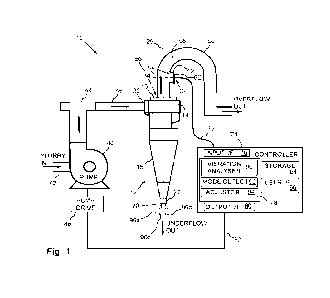
the lower outlet will
discharge a rope-shaped flow of coarse solids. Roping may also result in the
undesired effect
of some or a substantial part of the heavier phase being discharged through
the upper outlet.
A number of different operational conditions can cause roping, some of which
include
changes in the composition and viscosity of the slurry and increases in slurry
feed speed.
[005] The semi-roping state is characterised by improved hydrocyclone
efficiency and
increased density in the underflow. The semi-roping state is visually distinct
from both splash
mode and roping mode in that the slurry in the underflow discharge of the
hydrocyclone has
an increased solids percentage, and the splay angle (which is the internal
cone angle of the
discharge) of the slurry discharge is reduced (in other words, the cone shaped
discharge is
CA 03221984 2023- 12- 8
WO 2023/012697 PCT/1B2022/057216
2
narrower for the semi-roping state than for the splash state). The transition
state is that state
in which the hydrocyclone moves momentarily into, and then back out of, the
roping state.
[006] To prevent roping, many mine operators typically select a slurry flow
rate (or pressure)
such that there is a significant margin before the hydrocyclones would
experience roping.
This avoids the losses that result from having to shut down a hydrocyclone
that has entered
roping; however, a hydrocyclone operates most efficiently when it is almost at
the roping
condition. This problem is exacerbated where hydrocyclones are provided in a
cluster
arrangement because the margin of safety is typically determined based on the
hydrocyclone
that is closest to roping, so other hydrocyclones in the cluster may be
operating a long way
from roping, and therefore highly inefficiently.
[007] Prior art approaches, such as that disclosed in W02016/051275 are
directed to
detecting the onset of roping and preventing it occurring by changing the
operational state
back to the splash state.
[008] There is a need for new or improved systems and/or methods of
controlling the
operation of a hydrocyclone so that it operates more efficiently.
[009] The reference in this specification to any prior publication (or
information derived from
the prior publication), or to any matter which is known, is not, and should
not be taken as an
acknowledgment or admission or any form of suggestion that the prior
publication (or
information derived from the prior publication) or known matter forms part of
the common
general knowledge in the field of endeavour to which this specification
relates.
Summary
[010] According to a first aspect there is provided a method of controlling
the operation of a
hydrocyclone to maintain the hydrocyclone in a semi-roping or transition
operational state as
it separates a pumped fluid into an overflow stream and an underflow stream,
the method
comprising: measuring vibrations of the hydrocyclone at a selected frequency
within a
predetermined frequency range; comparing a characteristic of the measured
vibrations at the
selected frequency with a plurality of values representing transitions to a
high efficiency state
and a roping state, respectively, of the hydrocyclone to identify a current
operational state of
the hydrocyclone; generating an adjustment setting to change the identified
current
operational state to the high efficiency state, where the adjustment setting
increases or
decreases an operational parameter, such as a pumped fluid parameter.
[011] The high efficiency state may comprise both the semi-roping state and
the transition
state. A low efficiency state may comprise both the splash state and the
roping state. The
high efficiency state may be represented by a first value (indicating
transitions to a semi-
roping state) and a second value (indicating transitions to a transition
state). The second
value may be numerically larger than the first value.
CA 03221984 2023- 12- 8
WO 2023/012697 PCT/1B2022/057216
3
[012] The plurality of values representing transitions may represent
transitions (i) to a semi-
roping state, (ii) from the semi-roping state to a transition state, and (iii)
from the transition
state to a roping state.
[013] The pumped fluid may comprise slurry.
[014] The method may comprise detecting when a characteristic of the measured
vibrations
at the selected frequency is near to a value representing a transition to a
roping state of the
hydrocyclone and generating an adjustment value so that the characteristic is
still within the
semi-roping state but not as near the transition to the transition state as
previously measured.
[015] The selected frequency may vary by a small amount within the desired
frequency
range.
[016] The desired frequency range may comprise 1 to 50 Hz; 10 to 40Hz, 20 to
40Hz, or the
like. In some embodiments a frequency range of approximately 30 to 40 Hz may
be
advantageous.
[017] The values may be determined by implementing a calibration process on
the
hydrocyclone. The calibration process may involve forcing the operation of the
hydrocyclone
between the different states (for example, by changing the pump speed or
pressure of the
slurry) or modes of operation. For example, the hydrocyclone may be changed
from a splash
mode to a semi-roping mode, then to a transition mode, and then to a roping
mode. The
transition mode may be a mode in which the hydrocyclone switches between semi-
roping and
roping in an unstable manner. For each of these modes, the maximum amplitude
may be
recorded, and the frequency at which the maximum amplitude occurs. The maximum
amplitude will typically occur for the roping state, so this amplitude may be
set at the maximum
level, and the other amplitudes may be calibrated relative to the maximum
amplitude in the
roping state. For each mode, the maximum measured amplitude for that mode may
be used
as the changeover point indicating that the operating mode is expected to
change to the next
mode at that amplitude.
[018] Optionally, vibrations are measured from an air core of a hydrocyclone.
The vibrations
may be measured indirectly, for example, using a sensor coupled to a membrane
mounted
on an overflow outlet. The membrane vibrations may be related to the air core
frequency.
The membrane may be mounted on an overflow pipe from an overflow outlet of the
hydrocyclone. Alternatively, where an air core booster is fitted at the
overflow outlet of the
hydrocyclone, the membrane may be mounted on an upper surface (such as a top
surface)
of the air core booster.
[019] The characteristic of the measured vibrations preferably comprises an
amplitude of
the vibrations. The amplitude may be a direct measurement or a transformation
of the
CA 03221984 2023- 12- 8
WO 2023/012697 PCT/1B2022/057216
4
amplitude measurement. Alternatively, but less preferred, the characteristic
may comprise a
rate of change of the amplitude.
[020] The plurality of values may comprise two values: a low value and a high
value; wherein
any characteristic below the low value represents a first mode of operation,
any characteristic
at or above the low value but below the high value represents a second mode of
operation,
and any characteristic at or above the high value represents a third mode of
operation. The
first mode may correspond to a splash mode of operation, which is inefficient;
the second
mode may correspond to a semi-roping mode of operation, which is optimum
efficiency, the
third mode may correspond to a roping mode of operation which is highly
inefficient.
[021] Alternatively, the plurality of values may comprise three values: a low
value, a medium
value, and a high value; wherein any characteristic below the low value
represents a first
mode of operation, any characteristic at or above the low value but below the
medium value
represents a second mode of operation, any characteristic at or above the
medium value but
below the high value represents a third mode of operation and any
characteristic at or above
the high value represents a fourth mode of operation. The first mode may
correspond to a
splash mode of operation, which is inefficient; the second mode may correspond
to a semi-
roping mode of operation, which is optimum efficiency, the third mode may
correspond to a
transition mode, which may lead to the fourth mode of operation, which is the
roping mode.
[022] Optionally, the plurality of values may comprise more than three values.
[023] The method may comprise the further step of transmitting to a remote
display an
indication of which mode of operation the hydrocyclone is currently operating
in.
[024] The adjustment setting may comprise a speed adjustment for transmitting
to a variable
frequency drive (VFD) that controls a motor powering a pump (by rotating the
pump shaft at
a speed determined by the VFD) that pumps the pumped fluid. If the adjustment
setting is
negative then the VFD reduces the speed based on the value (i.e. the
magnitude) of the
adjustment setting. If the adjustment setting is positive then the VFD
increases the speed
based on the value (i.e. the magnitude) of the adjustment setting. If the
adjustment setting is
zero then the VFD does not change the speed. The speed adjustment may comprise
a
reference speed offset that is delivered to the VFD.
[025] By adjusting the speed of the pump, the pressure of the fluid is changed
(faster slurry
flow rate produces a higher pressure in a hydrocyclone), which quickly changes
the geometry
of the air core inside the hydrocyclone. This enables the hydrocyclone to be
operated in a
semi-roping or even transitional mode because if roping does occur it can be
quickly detected
and reversed by reducing the pumping speed. Detection of roping may be
implemented by
a comparator circuit coupled to the vibration sensor, so that if an amplitude
at the selected
frequency exceeds a threshold at which an undesired change of operating state
or mode
CA 03221984 2023- 12- 8
WO 2023/012697 PCT/1B2022/057216
occurs, for example, a changeover from semi-roping to transition mode, then
the comparator
circuit provides an output that is used as, or to generate, the adjustment
setting. The
comparator circuit may include a processor that implements a comparison or
weighting
algorithm.
[026] Alternatively, instead of, or in addition to, changing the pump speed,
one or more of
the following may be changed: (i) the fluid viscosity (for example, by adding
more water to
reduce the viscosity, or by adding additional particles to increase the
viscosity), (ii) a vortex
finder diameter at the overflow, (iii) an apex diameter at the underflow, or
(iv) the state of an
isolation valve (open or closed) on an inlet to a hydrocyclone.
[027] The method may comprise the further step of providing the adjustment
setting to a
device upstream of the hydrocyclone.
[028] Optionally, the adjustment setting includes an indication of an amount
to increase or
decrease a pumped fluid parameter. This amount may be indicated by a magnitude
of the
adjustment setting.
[029] Optionally the method further comprises: detecting when the
characteristic meets the
highest value of the plurality of values and implementing an intervention
process in response
thereto.
[030] The intervention process may comprise adjusting the pumped fluid
parameter
significantly to improve the probability of the characteristic meeting a lower
or the lowest,
value.
[031] The intervention process may further comprise stopping the pumped fluid
if adjusting
the pumped fluid parameter does not cause the characteristic to meet the lower
or lowest
value.
[032] The maximum amplitude for each operating mode may occur at a slightly
different
frequency to the maximum amplitude for the other operating modes, but the
maximum
amplitudes would typically be within the predetermined frequency range. The
amplitude may
be measured at the same frequency for all operating modes, or a slightly
different frequency
for some or all of the operating modes.
[033] According to a second aspect there is provided a method of controlling
the operation
of a hydrocyclone cluster comprising a plurality of hydrocyclones fed by a
fluid distributor to
maintain each hydrocyclone in a semi-roping or transition operational state,
the method
comprising: measuring vibrations from each of a plurality of hydrocyclones at
a selected
frequency in a predetermined frequency range; for each hydrocyclone, comparing
a
characteristic of the measured vibrations at the selected frequency with a
plurality of values
representing transitions to a semi-roping state, a transition state and a
roping state of the
hydrocyclones to identify a current operational state of each of the
hydrocyclones; generating
CA 03221984 2023- 12- 8
WO 2023/012697 PCT/1B2022/057216
6
an adjustment setting for each hydrocyclone to change the identified current
operational state
to, or maintain each hydrocyclone in, either the semi-roping or transition
desired operational
state; and using a weighting algorithm to generate a master adjustment setting
based on the
individual adjustment settings, where the master adjustment setting increases
or decreases
a pumped fluid parameter.
[034] The weighting algorithm may generate a master adjustment setting that
causes most
hydrocyclones to operate in an optimum range where the measured characteristic
is between
two values.
[035] The method may comprise the further step of identifying a hydrocyclone
that may
generate vibrations having a characteristic above the higher value in response
to the master
adjustment setting being implemented, and closing an isolation valve
associated with that
hydrocyclone.
[036] The method may further comprise identifying a hydrocyclone that may
generate
vibrations having a characteristic below the higher value in response to the
master adjustment
setting being implemented, and opening an isolation valve associated with that
hydrocyclone.
[037] By increasing the slurry flow rate, a higher pressure is created in a
manifold supplying
a plurality of hydrocyclones, and this transfers into a higher pressure in
each hydrocyclone.
[038] According to a third aspect there is provided a hydrocyclone for
separating pumped
fluid into a plurality of streams, the hydrocyclone comprising: an inlet for
receiving the pumped
fluid; a separation chamber in fluid communication with the inlet and
delivering a first fluid
stream to an overflow, and a second stream to an underflow; and a vibration
sensor mounted
on the hydrocyclone; and a controller operable to (i) measure vibrations of
the hydrocyclone
at a selected frequency within a predetermined frequency range; (ii) compare a
characteristic
of the measured vibrations at the selected frequency with a plurality of
values representing
transitions to a semi-roping state, a transition state and a roping state of
the hydrocyclone to
identify a current operational state of the hydrocyclone; (iii) generate an
adjustment setting to
change the identified current operational state to, or maintain each
hydrocyclone in, either the
semi-roping or transition state, where the adjustment setting increases or
decreases an
operational parameter, for example, a pumped fluid parameter.
[039] In some embodiments the adjustment setting may be used to move the
characteristic
closer to an upper value indicative of a transition to an undesired state.
This may be used
when the hydrocyclone is to be used as close as possible to the roping
condition, particularly
because the hydrocyclone is most efficient when it is operating close to the
roping condition.
[040] The hydrocyclone may include an overflow pipe coupled thereto. The
overflow pipe
may be coupled to a vortex finder, or to an air core booster coupled to the
vortex finder.
CA 03221984 2023- 12- 8
WO 2023/012697 PCT/1B2022/057216
7
[041] According to a fourth aspect there is provided a hydrocyclone system
comprising a
plurality of hydrocyclones according to the third aspect, where the plurality
of adjustment
settings created by the hydrocyclones are fed into a weighting algorithm to
create a master
adjustment setting based on the individual adjustment settings.
[042] The hydrocyclone system may further comprise: a density sensor in the
overflow of
each hydrocyclone or in a common overflow path fed into by each hydrocyclone
overflow;
and a density sensor in the underflow (either in a common underflow sump or in
each
individual hydrocyclone underflow). Measurements from these density sensors
may be fed
into the weighting algorithm. These measurement may be used to populate a
mathematical
model of the hydrocyclone and/or a cluster of hydrocyclones to represent mass
separation
and metallurgical characteristics of the hydrocyclone and/or cluster, such as
separation
efficiency, the P50 cut point the mineral mass in the overflow and the
underflow, and such like.
These measurement may be used to calculate a mathematical mass balance model
in real
time for the mill circuit in which the hydrocyclone cluster and feed pump are
installed and
operated. The mathematical mass balance model may be implemented as an
algorithm that
provides an output indicating the operating point of the pump and the cyclone
cluster, in
addition to the flow input parameters for the mill circuit (solids weight,
flow rate, density, and
the like) and flow output parameters from the mill circuit (solids weight,
flow rate, density, and
the like). This mathematical mass balance model can present this information
(for example,
on a user dashboard, on a screen panel on the equipment, or on an app on a
mobile device
carried by a user) as points plotted on a pump dynamic head and flow rate
curve, and as
points plotted on a hydrocyclone pressure and flow rate curve. A control
algorithm can be
used to adjust the parameters in response to the mathematical model to ensure
that the pump
and hydrocyclone clusters are operated in a predefined safe operating zone.
[043] The hydrocyclone system may further comprise a flow meter. Measurements
from
the flow meter may be fed into the weighting algorithm.
[044] The weighting algorithm may be implemented using deep learning, a
Bayesian
network, or any other convenient method.
[045] These and other aspects will be apparent from the following specific
description, given
by way of example only, with reference to the accompanying drawings, in which:
[046] Fig. 1 is a schematic view of part of a hydrocyclone system according to
a first
embodiment of the present invention;
[047] Fig. 2 is a simplified cross section view of part of the hydrocyclone
system of Fig. 1,
showing additional features (an overflow pipe and a sensing system) in more
detail;
[048] Fig. 3 is a flowchart illustrating steps performed in calibrating the
hydrocyclone system
of Fig. 1;
CA 03221984 2023- 12- 8
WO 2023/012697 PCT/1B2022/057216
8
[049] Fig. 4 is a flowchart illustrating steps performed in operating the
hydrocyclone system
of Fig. 1 to maintain the hydrocyclone system in a desired mode;
[050] Fig. 5 is a schematic plan view of a hydrocyclone system comprising a
cluster of
hydrocyclones of the type shown in the hydrocyclone system of Hg. 1, according
to a second
embodiment of the present invention;
[051] Fig. 6 is a schematic view of part of a hydrocyclone system according to
a third
embodiment of the present invention;
[052] Fig. 7 is a simplified cross section view of part of the hydrocyclone
system of Fig. 6,
showing features thereof in more detail;
[053] Fig. 8 is an example of a pump curve illustrating a safe operating zone
in which the
hydrocyclone system maintains the pump; and
[054] Fig. 9 is an example of a hydrocyclone curve illustrating a safe
operating zone in which
the hydrocyclone system maintains the hydrocyclone.
[055] Reference is now made to the drawings, and particularly to Fig. 1, which
is a
schematic view of part of a hydrocyclone system 10 according to a first
embodiment of the
present invention.
[056] The hydrocyclone system 10 comprises a plurality of conventional
hydrocyclones
(only one hydrocyclone 12 is illustrated in Fig. 1), each having a generally
cylindrical upper
chamber 14 at an upper end thereof, an overflow cap 16 (also referred to as a
vortex finder)
mounted on an upper surface of the cylindrical chamber 14 and extending
therein, and a
generally frusto-conical shaped separation chamber 18 extending from a lower
surface of the
cylindrical chamber 14 to an underflow outlet 20 at which a spigot 22 is
mounted.
[057] The upper chamber 14, vortex finder 16, separation chamber 18, and
spigot 22, are
mounted generally coaxially such that they define a longitudinal axis 26, also
referred to as a
central axis or a fluid transport axis.
[058] A feed inlet 30 is provided generally tangential to the longitudinal
axis 26 and
extending from the cylindrical chamber 14. An overflow outlet 34 comprises an
aperture
defined by the vortex finder 16 at an upper end of the cylindrical chamber 14.
[059] The feed inlet 30 is configured to allow slurry (liquid containing
suspended matter) to
be pumped therethrough and into the separation chamber 18 to create one or
more vortices
therein and an air core to effect separation of the slurry into large
particles reporting to the
underflow outlet 20 and small particles reporting to the overflow outlet 34.
[060] A centrifugal pump 40 is used to pump the slurry received on an input
hose (or pipe)
42 into a distributor 44 that separates the slurry into a plurality of
different hoses 46 (only one
is illustrated in Fig. 1), each distributor hose 46 feeding a hydrocyclone
feed inlet, such as
CA 03221984 2023- 12- 8
WO 2023/012697 PCT/1B2022/057216
9
feed inlet 30. The centrifugal pump 40 is driven by a motor (not shown for
clarity) controlled
by a conventional variable frequency drive (VFD) controller 48.
[061] In this embodiment, an overflow pipe 50 leads from the overflow outlet
34 to a tank
(not shown) for accumulating fine particulate slurry for use in ore extraction
(for example, via
flotation). However, in other embodiments, the overflow pipe 50 may lead to
another desired
processing stage.
[062] Reference will now also be made to Fig. 2, which is a simplified cross
section view of
part of the overflow pipe 50, showing additional features in more detail.
[063] The overflow pipe 50 defines a flanged protrusion 52 relatively close to
an upper
portion of the vortex finder 16 defining an opening 54 along a lateral axis 56
generally
perpendicular to the longitudinal axis 26. The opening 54 is in fluid
communication with the
internal passageway 58 of the overflow pipe 50.
[064] A sensor assembly 60 is mounted to the flanged protrusion 52 and
comprises a
membrane 62 coupled to the flanged protrusion 52 by an annular mount 64 (in
the form of a
metal ring in this embodiment) and bolts 66 extending therethrough and into
the flanged
protrusion 52. The annular mount 64 and membrane 52 combination seals the
opening 54
(and thereby prevents fluid egress therefrom). The membrane 62 defines a
generally central
mounting zone 68 to which a vibration sensor 70 may be coupled. Various
configurations of
sensor assembly 60 may be used. In this embodiment, the sensor assembly 60 is
similar to
those described in W02019/173874, which is owned by the assignee of this
application.
[065] In this embodiment, the membrane 62 is in the form of an elastomer
membrane.
However, in other embodiments, the sensor assembly may use a non-elastomeric
flexible
sheet.
[066] Mounting the membrane 62 outside the internal passageway 58 ensures that
it does
not impede or obstruct overflow material flowing therethrough; however,
membrane 62 comes
into contact with overflow material (as the overflow material flows up the
internal passageway
58) and can therefore be used to measure directly, for example, a vibration of
the overflow
material (for example, a vibration or pulsation of the overflow material
transverse to the main
direction of flow of the overflow material through the internal passageway
58). It is believed
that the vibration of the overflow material detected by the membrane 62 is
directly related to
the vibration of the air core in the separation chamber 18 of the hydrocyclone
12.
[067] In this embodiment, the vibration sensor 70 comprises an accelerometer.
A suitable
accelerometer for use in this embodiment is an Integrated Electronics Piezo-
Electric (IEPE)
sensor, such as those available from PCB of 3425 Walden Avenue, Depew, NY
14043, USA.
Alternative accelerometers, such as wireless accelerometers, may be used
instead of, or in
addition to, a wired accelerometer. The vibration sensor 70 couples to the
mounting zone
CA 03221984 2023- 12- 8
WO 2023/012697
PCT/1B2022/057216
68, for example, using complementary formations on a sensor holder and the
mounting zone
68, such as a bayonet fitting, or a screw thread fitting.
[068] A vibration sensor cable 72 provides an electrical connection between
the vibration
sensor 70 and a cyclone controller 74.
[069] In this embodiment the cyclone controller 74 is based on C6015
(communications
gateway) and C6017 ultra-compact industrial PC, available from Beckhoff
Automation GmbH
& Co. KG, Huelshorstweg 20, 33415 Verl, Germany ("Beckhoff"). These devices
are used as
a controller and field gateway, and include accelerometer input modules, such
as the EL3632
2-channel analogue input terminal for condition monitoring, also available
from Beckhoff. The
cyclone controller 74 may execute TF3600 TC3 condition monitoring software
available from
Beckhoff.
[070] The cyclone controller 74 comprises an input interface 76 for coupling
to vibration
sensor cable 72, one or more processors 78 for implementing various analytical
functions, an
output interface 80 for coupling to the VFD controller 48 via a pump control
cable 82, non-
volatile storage 84, and a user interface 86. The user interface 86 may
comprise an LCD
screen, LED lights, or any other convenient visual or audio interface.
[071] The input interface 76 comprises a plurality of EL3632 accelerometer
input modules.
Each vibration sensor 70 has a unique identification, and the unique
identification is mapped
to the particular hydrocyclone 12 (only one is illustrated in Fig. 1, but a
cluster of
hydrocyclones is typically provided, each hydrocyclone 12 having a dedicated
vibration
sensor 70). This ensures that the cyclone controller 74 can indicate which
hydrocyclone 12
is being analysed.
[072] The processor 78 is programmed to implement three main functions
(illustrated by
functional blocks in Fig. 1): a vibration analysis function 90, a mode
detection function 92,
and an adjustment function 94. These three functions may be performed by a
configured
instance of the TF3600 TC3 condition monitoring software. They may also be
performed by
a software implementation of a mathematical model of the operation of the
hydrocyclone 12.
[073] Hydrocyclones, such as hydrocyclone 12, can operate in multiple
different modes. A
first mode is referred to as splash (or splashing) mode. This mode is
illustrated in Fig. 1 by
broken lines 96a. In splash mode the slurry exiting the spigot 22 has a
relatively wide splay
angle. A second mode is referred to as semi-roping mode. This mode is
illustrated in Fig. 1
by broken lines 96b. In semi-roping mode the slurry exiting the spigot 22 has
a medium splay
angle, narrower than splash mode. A third mode is referred to as roping mode.
This mode
is illustrated in Fig. 1 by broken lines 96c. In roping mode the slurry
exiting the spigot 22 is a
rope-shaped flow of coarse solids because the air core within the separation
chamber 14 has
collapsed (or is close to collapsing).
CA 03221984 2023- 12- 8
WO 2023/012697
PCT/1B2022/057216
11
[074] There is also a fourth mode of operation referred to as a transition
mode. In the
transition mode, the operation of the hydrocyclone 12 moves momentarily into,
and then back
out of, the roping mode. The transition mode is the most efficient operating
mode for the
hydrocyclone 12 in terms of sharpness of cut (the particle size separation
between the heavier
particles reporting to the underflow outlet 20 and the lighter particles
reporting to the overflow
outlet 34), but if roping mode is entered more than momentarily then no
separation occurs
and the hydrocyclone 12 may need to be shut down and restarted. This is very
inefficient
and expensive in terms of productivity loss.
[075] In this embodiment, the operation of the hydrocyclone 12 can be
controlled so that it
is on the verge of the roping mode, without actually entering the roping mode
more than
momentarily. In other words, this embodiment allows the hydrocyclone 12 to be
operated in
transition mode or at the edge of semi-roping mode.
[076] The operation of the hydrocyclone system 10, and particularly the
cyclone controller
74, will now be described with reference to Fig. 3, which is a flowchart 100
illustrating steps
performed in calibrating the controller 74 for use with the hydrocyclone 12.
It is desirable to
calibrate the controller 74 for use with each hydrocyclone 12 due to
variations in slurries being
separated at different locations, variations in the operation and wear
characteristics of the
hydrocyclone, and other factors. However, in some embodiments, a general
calibration may
be performed once, for example as a factory setting, and only updated if
required.
[077] Initially, a frequency range for measurements is selected (step 102) and
programmed
into the cyclone controller 74. In this embodiment, a frequency range between
10Hz and
50Hz is used, as the important vibrations from the air core are usually found
in this range.
However, in other embodiments different frequency ranges may be used,
depending on the
slurry type, density, pump speed, hydrocyclone hydrodynamics, or other
factors. The cyclone
controller 74 may be pre-programmed with this frequency range so that it only
needs updated
if a different frequency range is desired.
[078] The hydrocyclone system 10 is then started (step 104). The operating
mode of the
hydrocyclone 12 is then detected (step 106). This may be performed manually by
inspecting
the underflow slurry exiting the spigot 22, or it may be performed using a
mode detector (such
as a sensor measuring the angle of spread of the underflow slurry from the
spigot 22).
[079] The cyclone controller 74 then adjusts the speed of the pump 40 to
change the
operating mode to (or maintain the operating mode in) the splash mode (step
108). This
adjustment may be triggered by an operator or may be performed automatically.
[080] The operating mode of the hydrocyclone 12 is then detected (step 110) to
ensure that
it is in splash mode. If not, then the pump 40 is further adjusted (back to
step 108) and step
110 is repeated. If the hydrocyclone 12 is operating in splash mode, then
amplitude
CA 03221984 2023- 12- 8
WO 2023/012697
PCT/1B2022/057216
12
measurements are recorded (using the vibration sensor 70) across the defined
frequency
range (10Hz to 50Hz in this embodiment) (step 112), including the maximum
amplitude, and
the frequency at which that maximum amplitude is measured.
[081] The cyclone controller 74 then adjusts the speed of the pump 40 to
change the
operating mode to the next mode (in this embodiment, the semi-roping mode)
(step 114).
This adjustment may be triggered by an operator or may be performed
automatically.
[082] The operating mode of the hydrocyclone 12 is then detected (step 116) to
ensure that
it is in semi-roping mode. If not, then the pump 40 is further adjusted (back
to step 114) and
step 116 is repeated.
[083] The pump speed adjustment and mode detection are performed iteratively
(with
relatively small adjustments to the pump speed) so that the point at which the
mode changes
is recorded. This is important as it will be used to create a lower amplitude
level at which a
transition into an operating mode occurs. For all modes other than the roping
mode, the
maximum amplitude occurs where the mode transitions into the next mode nearer
to roping
(e.g. splash to semi-roping, or semi-roping to transition, or transition to
roping). This
maximum amplitude will be used to calculate the upper amplitude level for that
mode, as
described in more detail below.
[084] If the hydrocyclone 12 is operating in semi-roping mode, then amplitude
measurements are recorded across the defined frequency range (10Hz to 50Hz in
this
embodiment) (step 118), including the maximum amplitude, and the frequency at
which that
maximum amplitude is measured.
[085] Steps 114 to 118 are repeated for all modes until all modes have been
measured
(step 120). In this embodiment, four modes are used: splash; semi-roping;
transition; and
roping. For each of these modes, the cyclone controller 74 records the maximum
amplitude
at which the next mode is entered, and the maximum amplitude during operation
in that mode.
[086] The amplitudes and frequency for each mode are then selected to complete
the
calibration process (step 122). In this embodiment, all measurements during
the normal
operation of the hydrocyclone 12 (as opposed to operation of the hydrocyclone
12 during the
calibration process 100) are taken at a single frequency within the frequency
range. The
single frequency selected is the frequency at which the maximum amplitude
during roping
mode is detected. Roping mode typically gives rise to the largest vibrations
in the air core,
so the largest vibration amplitudes occur during roping mode. In this
embodiment, as an
example, the selected frequency is 30Hz because the maximum amplitude during
roping
occurs at 30Hz (as an example). The measured vibration in roping mode is used
to calibrate
the other maximum amplitudes (i.e. the maximum amplitude of each of the other
modes at
that frequency are divided by the maximum amplitude in the roping mode at that
frequency).
CA 03221984 2023- 12- 8
WO 2023/012697
PCT/1B2022/057216
13
This gives a maximum amplitude at roping of 1Ø The lower level of each mode
is the
amplitude at which the mode of the hydrocyclone 12 changes to that mode (which
was also
detected during the calibration process described above). An example of
calibrated
amplitudes for four operating modes is shown below in Table 1.
Frequency (Hz) Upper amplitude Lower amplitude
Roping mode 30 1.00 0.05
Transition mode 30 0.05 0.04
Semi-roping mode 30 0.04 0.03
Splash mode 30 0.03 0.00
Table 1 Example Upper and Lower Amplitudes for each Operating Mode
[087] These upper and lower amplitude values, together with the operating mode
they
correspond to, and the frequency at which the measurements were taken
(collectively the
"measurement parameters"), are stored in the non-volatile storage 84 in the
cyclone controller
74.
[088] The operation of the hydrocyclone system 10 will now be described with
reference to
Fig. 4, which is a flowchart 140 illustrating steps performed in maintaining
the hydrocyclone
system in a desired mode (the upper region of the semi-roping mode in this
embodiment)
(referred to as the optimised operation process 140).
[089] Initially, the hydrocyclone system 10 is started by pumping slurry
through the
hydrocyclone 12 (step 142).
[090] The cyclone controller 74 then retrieves the measurement parameters from
the non-
volatile memory 84 (step 144), which includes the selected frequency (30Hz) at
which
measurements are to be taken. This step may occur before, during, or after the
hydrocyclone
system start-up step (step 142).
[091] The cyclone controller 74 then receives the vibration measurements from
the vibration
sensor 70 and uses the vibration analysis function 90 to identify the
vibration signal amplitude
measured at this selected frequency (30Hz) (step 146).
[092] The cyclone controller 74 then uses the mode detection function 92 to
compare the
vibration signal amplitude measured at the selected frequency (30Hz) with the
upper and
lower values retrieved from the non-volatile memory 84 (step 148). In this
way, the cyclone
controller 74 identifies the current operating mode of the hydrocyclone 12
(step 150) and
presents this on the user interface 86 (step 152). Optionally, the cyclone
controller 74
transmits this to a remote control centre, such as a distributed control
system (DCS), where
information about different types of equipment on the particular site is
collated, processed
and reviewed.
CA 03221984 2023- 12- 8
WO 2023/012697
PCT/1B2022/057216
14
[093] The cyclone controller 74 then uses the adjustor function 94 to
ascertain if an
adjustment needs to be made to move the hydrocyclone operating mode to the
desired mode
(step 154), and to generate an adjustment value, if required (step 156).
[094] In this embodiment, the adjustor function 94 is implemented by a PI D (a
proportional¨
integral¨derivative) controller.
[095] If no adjustment is required then the process repeats from step 146
(identifying the
measured vibration amplitudes).
[096] The PI D controller provides an adjustment setting based on the current
measured
amplitude and the desired amplitude. The bigger the difference between the
current
measured amplitude and the lower level amplitude of the semi-roping mode, the
larger the
adjustment setting. To move the operating mode of the hydrocyclone 12 from
splash mode
to semi-roping mode, the pump speed is increased; whereas, if roping mode is
entered, the
pump speed is decreased to move the operating mode to transition mode or semi-
roping
mode. Once the adjustment setting has been ascertained, it is then transmitted
to the VFD
controller 48 as a reference speed offset via the pump control cable 82. The
VFD controller
48 then adjusts the pump speed accordingly.
[097] This adjustment process (steps 146 through 158) is repeated continually,
which has
two advantages. Firstly, it allows the operating mode to be moved iteratively
towards the
desired mode without having to over-compensate by using too large an
adjustment.
Secondly, it enables any change of operating mode into transition mode or
roping mode to
be detected and corrected very quickly. This allows the hydrocyclone system 10
to be
operated close to transition or roping mode, without the risk of being in
roping mode for so
long that the air core collapses.
[098] Reference is now made to Fig. 5, which is a schematic plan view of a
hydrocyclone
system 210 comprising a cluster of eight hydrocyclones 12a,b,c
h, each similar to
hydrocyclone 12. Each hydrocyclone 12 is disposed at an angle so that the
spigots 22 are
all in close proximity disposed in a ring formation and the overflow outlets
34 are relatively
further apart.
[099] Each hydrocyclone 12a,b,c h has an isolation valve 224 on its
distributor hose 46
so that each hydrocyclone 12a,b,c h can be selectively turned on or off, as
desired. This
may be used to control the overall pressure in the distributor 44, or the
pressure in each of
the hydrocyclones 12a,b,c ... h.
[0100] The hydrocyclone system 210 also comprises an enhanced cyclone
controller 274
that receives inputs from the eight vibrational sensors 70 (one on each
hydrocyclone 12a,b,c
h). The enhanced cyclone controller 274 also receives inputs (not shown) from
a density
sensor 275 (in the form of an ultrasonic sensor in this embodiment) located in
an overflow
CA 03221984 2023- 12- 8
WO 2023/012697
PCT/1B2022/057216
tank 276 fed from the overflow pipes 50 of each of the hydrocyclones 12a,b,c h
(although
only one overflow pipe 50c is shown in Fig. 5 for clarity), and from a density
sensor 277 (in
the form of an ultrasonic sensor in this embodiment) located in an underflow
tank 278 fed
from a sump (not shown) into which the underflow from each spigot 22 is
collected.
[0101] The overflow tank 276 has an outlet pipe (not shown) that allows fluid
from the
overflow tank 276 to be transported to other stages of processing, such as
further separation
stages, or flotation stages.
[0102] The enhanced cyclone controller 274 may also receive inputs from other
sensors
(such as pressure sensors, flow rate sensors, and the like) distributed
throughout the
hydrocyclone system 210 and mounted on or in different parts thereof.
[0103] The enhanced cyclone controller 274 includes an additional processing
module 279
for receiving signals from the various sensors that are included in the
hydrocyclone system
210, and for controlling equipment in the hydrocyclone system 210 in response
to these
signals. To achieve this, the enhanced cyclone controller 274 includes
additional outputs,
illustrated by block 280 in Fig. 5. These additional outputs 280 are connected
to the isolation
valves 224a through h, and a water tank 281 for adding water to the slurry
being fed into the
pump 40. By adding water to the slurry, the slurry becomes less dense (less
viscous), which
affects the pressure within each hydrocyclone 12.
[0104] The additional processing module 279 can detect when an operating mode
in one
hydrocyclone (e.g. hydrocyclone 12a) is significantly different to that of the
other
hydrocyclones, and can shut off that hydrocyclone (e.g. hydrocyclone 12a) by
closing its
associated isolation valve 224a. The additional processing module 279 may open
a closed
isolation valve (e.g. 224g) associated with a hydrocyclone that is not
currently in use (e.g.
hydrocyclone 12g) to balance the pressures in the cluster of hydrocyclones
that are
operational.
[0105] The hydrocyclone system 210 may combine the adjustment settings for
each
hydrocyclone being operated to generate a master adjustment setting based on
the individual
adjustment settings. The combination of adjustment settings may be implemented
using a
conventional weighting algorithm. This master adjustment setting may be
transmitted to the
pump 40.
[0106] Reference is now made to Fig. 6, which is a schematic view of part of a
hydrocyclone
system 310 according to a third embodiment of the present invention, and Fig.
7, which is a
simplified cross section view of part of the hydrocyclone system 310, showing
features thereof
in more detail;
[0107] The hydrocyclone system 310 is very similar to hydrocyclone system 10,
but
hydrocyclone 312 includes a conventional air core booster 336, and a sensor
assembly 360
CA 03221984 2023- 12- 8
WO 2023/012697
PCT/1B2022/057216
16
is mounted on an upper portion, in this embodiment a top surface 337, of the
air core booster
336. A vibration sensor 370 is mounted on a membrane 362 near the centre of
the sensor
assembly 360 (approximately aligned with the longitudinal axis 26) and
measures vibrations
in the air core of the hydrocyclone 312. The vibration sensor 370 and membrane
362 are
coupled to an annular mount 364 coupled to the top surface 337 by bolts 366.
The top surface
337 may be recessed with respect to sidewalls of the air core booster 336, for
example, it
may have a frusto-conical shape, as shown in Fig. 7. In this embodiment, the
start of the
overflow pipe 350 is generally perpendicular to the longitudinal axis 26;
whereas, for
hydrocyclone 12 the start of the overflow pipe 50 is generally parallel to the
longitudinal axis
26.
[0108] The membrane 362, annular mount 364, bolts 366, and vibration sensor
370 may be
very similar or identical to the corresponding features in hydrocyclone system
10.
[0109] Hydrocyclones with air core boosters produce improvements in capacity
and cyclone
efficiency by reducing the total pressure across the hydrocyclone, increasing
the volume flow
split to the overflow. An air core booster allows the use of a larger apex
finder (spigot) for a
given bypass of water to the underflow, which produces a more stable, larger
diameter air
core, increasing capacity and reducing bypass of fines. Air core boosters also
reduce the
chances of operating the hydrocyclone under roping conditions.
[0110] The operation of the hydrocyclone system 310 is the same as that of the
hydrocyclone
system 10, except that the sensor assembly 360 is mounted at a different
location to sensor
assembly 60, but both sensors 60, 360 measure the vibrations of the air core
in the
hydrocyclone 12, 312 and process the vibration measurements in the same way.
[0111] The cyclone controller 74, 274 in the hydrocyclone systems 10, 210, 310
described
above may provide alerts and recommendations about adjustments that an
operator may
make to these systems 10, 210, 310 to improve their performance.
[0112] The cyclone controller 74, 274 may include a software representation of
a
mathematical model of a hydrocyclone to calculate the efficiency and
metallurgical
parameters of an individual hydrocyclone or a cluster of hydrocyclones.
[0113] Hydrocyclone system 210 may include a flow meter in a central slurry
feed to the
hydrocyclone cluster. Additional sensors that may be used to collect
measurements from the
central slurry feed input include a pressure sensor, a slurry feed density
sensor, and sensors
to detect the state of each isolation valve 224 (open or closed condition).
Some or all of these
sensors may be used to create a full autonomous system for controlling the
operation of the
hydrocyclone system 10, 210, 310.
[0114] The cyclone controller 74, 274 may control the pump 40 and
hydrocyclones 12, 312
in such a way as to ensure they operate in a preferred hydraulic range. Fig. 8
is an example
CA 03221984 2023- 12- 8
WO 2023/012697
PCT/1B2022/057216
17
of a pump curve 401 illustrating a safe operating zone 403 in which the
hydrocyclone system
10, 310 maintains the pump 40. The points (indicated generally by arrow 405)
illustrate the
measured flowrate and head at various times, and the cyclone controller 74,
274 uses the
various measurements recorded from the sensors described above to adjust the
pump
flowrate or pressure to the pump to maintain operation in (or return operation
to) the preferred
operating zone 403. Similarly, Fig. 9 is an example of a hydrocyclone curve
411 illustrating
a safe operating zone 413 in which the hydrocyclone system 10, 310 maintains
the
hydrocyclone 12, 312. The points (indicated generally by arrow 415) illustrate
the measured
flowrate and pressure (in the cyclone distributor feed) at various times, and
the cyclone
controller 74, 274 uses the various measurements recorded from the sensors
described
above to adjust the pump flowrate or pressure to the pump to maintain
operation in (or return
operation to, for example for out of range point 417) the preferred operating
zone 403.
[0115] It will now be appreciated that these embodiments have the advantage of
being able
to operate hydrocyclones at a high efficiency (in a semi-roping or even
transitional mode,
collectively referred to as "high efficiency modes" or "high efficiency
states") because the
pressure of the fluid can be changed quickly by adjusting the speed of the
pump, which quickly
changes the geometry of the air core inside the hydrocyclone. This enables the
hydrocyclone
to be operated because if roping does occur it can be quickly detected and
reversed by
reducing the pumping speed.
[0116] In the above embodiments a controller is used based on off-the-shelf
parts configured
with specific parameters to define the upper and lower amplitudes of each
mode; but in other
embodiments the controller may be based on a conventional PC that is
programmed with
software (such as a trained deep learning model) to perform vibration
analysis, mode
detection, and adjustment generation.
[0117] In other embodiments, instead of, or in addition to, changing the pump
speed, one or
more of the following may be changed: (i) the fluid viscosity (for example, by
adding more
water to reduce the viscosity, or by adding additional particles to increase
the viscosity), (ii) a
vortex finder diameter at the overflow, (iii) an apex diameter at the
underflow, or (iv) the state
of an isolation valve (open or closed) on an inlet to a hydrocyclone.
[0118] In other embodiments, the amplitude may be measured at a different
frequency for
some or all of the operating modes.
[0119] In other embodiments, each hydrocyclone 12 may be mounted at an oblique
angle, in
a more horizontal than vertical orientation, depending on the application for
which the
hydrocyclones 12 are used. In other embodiments, a different motor controller
may be used
than a variable frequency drive controller.
CA 03221984 2023- 12- 8
WO 2023/012697
PCT/1B2022/057216
18
[0120] In other embodiments, a different frequency range may be used (for
example, 20Hz
to 60Hz, 5Hz to 80Hz, 30Hz to 45Hz, or the like). In other embodiments, the
maximum
amplitude for each operating mode may be recorded, even if each maximum
amplitude for
the modes occur at a different frequency.
[0121] In other embodiments, the characteristic of the measured vibrations may
comprise a
different property to an amplitude of the vibrations.
CA 03221984 2023- 12- 8
WO 2023/012697
PCT/1B2022/057216
19
Reference Numerals
10, 310 hydrocyclone system 100 calibration flowchart
12, 312 hydrocyclone 102 frequency range
selection step
14 upper chamber 104 start hydrocyclone
system
16 overflow cap / vortex finder 106 detect operating
mode
18 separation chamber 108 adjust pump speed for
splash mode
20 underflow outlet 110 detect operating mode
to confirm
splash mode
22 spigot 112 measure amplitudes
across
frequency range
26 longitudinal axis 114 adjust pump speed for
next mode
30 feed inlet 116 confirm desired
operating mode
34 overflow outlet 118 measure amplitudes
across
frequency range
40 centrifugal pump 120 confirm all modes
measured
42 centrifugal pump input hose 122 finalise calibration
44 distributor
46 distributor hose 140 optimised operation
process
48 variable frequency drive 142 start hydrocyclone
system
controller
50, 350 overflow pipe 144 retrieve measured
parameters
52 flanged protrusion 146 record vibration
amplitude
54 opening 148 compare with stored
amplitude
values
56 lateral axis 150 identify current
operating mode
58 internal passageway 152 display current
operating mode
60, 360 sensor assembly 154 ascertain if adjustment
needed
62, 362 membrane 156 create adjustment value
64, 364 annular mount 158 transmit adjustment
value
66, 366 bolts
68 mounting zone 210 hydrocyclone system
70, 370 vibration sensor 224 isolation valves
72 sensor cable
74 cyclone controller 274 enhanced cyclone
controller
76 input interface 275 density sensor
78 processor 276 overflow tank
80 output interface 277 density sensor
82 pump control cable 278 underflow tank
84 non-volatile storage 279 additional processing
module
86 user interface 280 additional outputs
90 vibration analysis 281 water tank
92 mode detection
94 adjustment 336 air core booster
96a splash mode 337 upper portion (e.g. top
surface)
96b semi-roping mode
96c roping mode 401 pump curve
403 safe operating zone
405 pump operating points
411 hydrocyclone curve
413 safe operating zone
415 hydrocyclone operating points
417 out of range point
CA 03221984 2023- 12- 8