Note: Descriptions are shown in the official language in which they were submitted.
WO 2023/043517
PCT/US2022/035048
PATIENT SUPPORT APPARATUS WITH
MULTIPLE DRIVING MODES
CROSS-REFERENCE TO RELATED APPLICATIONS
100011 The subject patent application claims priority to, and all the benefits
of, United
States Provisional Patent Application No. 63/244,884, filed on September 16,
2021, the entire
contents of which are incorporated by reference herein.
BACKGROUND
100021 Patient support systems facilitate care of patients in a health care
setting. Patient
support systems may comprise patient support apparatuses such as, for example,
hospital beds,
stretchers, cots, wheelchairs, and transport chairs, to move patients between
locations. A
conventional patient support apparatus comprises a base, a patient support
surface, and several
support wheels, such as four swiveling caster wheels. Often, the patient
support apparatus has one
or more non-swiveling auxiliary wheels, in addition to the four caster wheels.
The auxiliary wheel,
by virtue of its non-swiveling nature, is employed to help control movement of
the patient support
apparatus over a floor surface in certain situations.
100031 Those having ordinary skill in the art will appreciate that patient
support
apparatuses which employ powered auxiliary wheels can advantageously help
caregivers propel,
position, and manipulate the patient support apparatus. For example, powered
auxiliary wheels
can help caregivers move the patient support apparatus up or down ramps,
around corners, and the
like, and also may facilitate fine positioning of the patient support
apparatus in rooms, elevators,
and the like.
100041 While patient support apparatuses have generally performed well for
their intended
use, there remains a need in the art for improved usability and adaptability
to enable utilization of
patient support apparatus in and between different environments and use case
scenarios.
SUMMARY
100051 The present disclosure is directed towards a patient support apparatus
with a
support structure. A support wheel is coupled to the support structure. The
patient support
apparatus also includes a drive system with a drive member coupled to the
support structure to
influence motion of the patient support apparatus over a floor surface, a
motor coupled to the drive
member to operate the drive member at a speed, and a motor control circuit for
transmitting power
CA 03223998 2023- 12- 22
WO 2023/043517
PCT/US2022/035048
signals from a power source to the motor. The patient support apparatus also
includes a graphical
user interface for receiving user commands from a user to operate the drive
system. The patient
support apparatus also includes a control system coupled to the graphical user
interface and the
drive system for operating the drive system, the control system including: a
memory device
configured to store a plurality of drive profiles, and a controller coupled to
the memory device and
configured to: receive a first user command to select a first drive profile;
select the first drive
profile from the plurality of stored drive profiles; generate an output signal
based on the selected
drive profile; and transmit the generated output signal to the motor control
circuit to operate the
motor to operate the drive member in a first drive mode based on the selected
drive profile.
100061 The present disclosure is also directed towards a patient support
apparatus with a
support structure, a support wheel coupled to the support structure, and a
drive system including a
drive member coupled to the support structure to influence motion of the
patient support apparatus
over a floor surface, a motor coupled to the drive member to operate the drive
member at a speed,
and a motor control circuit for transmitting power signals from a power source
to the motor. The
patient support apparatus also includes a control system coupled to the drive
system for operating
the drive system, the control system including: a memory device configured to
store a plurality of
drive profiles, and a controller coupled to the memory device and configured
to: detect a first drive
profile based on at least one of a user input and a location associated with
the patient support
apparatus; select the first drive profile from the plurality of stored drive
profiles; generate an output
signal based on the selected drive profile; and transmit the generated output
signal to the motor
control circuit to operate the motor to operate the drive member in a first
drive mode based on the
selected drive profile.
100071 The present disclosure is also directed towards a patient support
apparatus with a
support structure, a support wheel coupled to the support structure, and a
drive system including a
drive member coupled to the support structure to influence motion of the
patient support apparatus
over a floor surface, a motor coupled to the drive member to operate the drive
member at a speed,
and a motor control circuit for transmitting power signals from a power source
to the motor. The
patient support apparatus also includes a control system coupled to the drive
system for operating
the drive system, the control system including: a memory device configured to
store a plurality of
drive profiles, and a controller coupled to the memory device and configured
to: detect a first
location of the patient support apparatus; select a first drive profile from
the plurality of stored
2
CA 03223998 2023- 12- 22
WO 2023/043517
PCT/US2022/035048
drive profiles based on the location of the patient support apparatus;
generate an output signal
based on the selected drive profile; and transmit the generated output signal
to the motor control
circuit to operate the motor to operate the drive member in a first drive mode
based on the selected
drive profile.
[0008] The present disclosure is also directed towards a method of operating a
drive system
coupled to a patient support apparatus. The method includes receiving a first
user command to
select a first drive profile. The method also includes selecting the first
drive profile from the
plurality of stored drive profiles. The method also includes generating an
output signal based on
the selected drive profile. The method also includes transmitting the
generated output signal to
the motor control circuit to operate the motor to operate the drive member in
a first drive mode
based on the selected drive profile.
BRIEF DESCRIPTION OF THE DRAWINGS
[0009] Figure 1 is a perspective view of a patient support apparatus,
according to the
present disclosure.
[0010] Figure 2 is a perspective view of an auxiliary wheel assembly of the
patient support
apparatus coupled to a base of the patient support apparatus shown in Figure
1.
100111 Figure 3 is a perspective view of the auxiliary wheel assembly shown in
Figure 2.
[0012] Figure 4 is an elevational view of the auxiliary wheel assembly shown
in Figure 2
in a retracted position.
[0013] Figure 5 is an elevational view of the auxiliary wheel assembly shown
in Figure 2
in a deployed position.
[0014] Figure 6 is a perspective view of a handle and a throttle assembly that
may be used
with the patient support apparatus shown in Figure 1.
[0015] Figure 7A is an elevational view of a first position of a throttle of
the throttle
assembly relative to the handle.
[0016] Figure 7B is an elevational view of a second position of the throttle
relative to the
handle.
[0017] Figure 7C is an elevational view of a third position of the throttle
relative to the
handle.
[0018] Figure 7D is another elevational view of the first position of the
throttle relative to
the handle.
3
CA 03223998 2023- 12- 22
WO 2023/043517
PCT/US2022/035048
[0019] Figure 7E is an elevational view of a fourth position of the throttle
relative to the
handle.
[0020] Figure 7F is an elevational view of a fifth position of the throttle
relative to the
handle
[0021] Figure 8 is a schematic view of a control system of the patient support
apparatus
shown in Figure 1.
[0022] Figure 9 is a schematic wire diagram of an auxiliary wheel assembly
control circuit
that may be used with the auxiliary wheel assembly shown in Figure 1.
[0023] Figure 10 is a schematic wire diagram of a motor control circuit that
may be used
with the auxiliary wheel assembly shown in Figure 1
[0024] Figure 11 is a flowchart illustrating an illustrative algorithms that
may be executed
by the control system of the patient support apparatus for operating the
auxiliary wheel assembly,
according to versions of the present disclosure.
[0025] Figures 12-14 illustrate data files that may be used with the algorithm
illustrated
that may be executed by the control system of the patient support apparatus
shown in Figure 11,
according to versions of the present disclosure.
[0026] Figure 15 illustrates a graphical user interface that may receive user
commands
from a user to operate the auxiliary wheel assembly.
[0027] Figure 16 illustrates a graphical user interface that may receive user
commands
from a user to operate the auxiliary wheel assembly in a first drive mode
based on a drive profile
[0028] Figures 16A-16B illustrate data files that may be used with an
algorithm illustrated
that may be executed by the control system of the patient support apparatus
shown in Figure 11
according to the drive mode shown in Figure 16.
[0029] Figure 17 illustrates a graphical user interface that may receive user
commands
from a user to operate the auxiliary wheel assembly in a second drive mode
based on a drive
profile.
[0030] Figures 17A-17B illustrate data files that may be used with an
algorithm illustrated
that may be executed by the control system of the patient support apparatus
shown in Figure 11
according to the drive mode shown in Figure 17.
4
CA 03223998 2023- 12- 22
WO 2023/043517
PCT/US2022/035048
DETAILED DESCRIPTION
[0031] Referring to Figure 1, a patient transport system comprising a patient
support
apparatus 10 is shown for supporting a patient in a health care setting. The
patient support
apparatus 10 illustrated in Figure 1 comprises a hospital bed. In some
versions, however, the
patient support apparatus 10 may comprise a stretcher, a cot, a wheelchair,
and a transport chair,
or similar apparatus, utilized in the care of a patient to transport the
patient between locations.
[0032] A support structure 12 provides support for the patient. The support
structure 12
illustrated in Figure 1 comprises a base 14 and an intermediate frame 16. The
base 14 defines a
longitudinal axis 18 from a head end to a foot end. The intermediate frame 16
is spaced above the
base 14. The support structure 12 also comprises a patient support deck 20
disposed on the
intermediate frame 16. The patient support deck 20 comprises several sections,
some of which
articulate (e.g., pivot) relative to the intermediate frame 16, such as a
fowler section, a seat section,
a thigh section, and a foot section. The patient support deck 20 provides a
patient support surface
22 upon which the patient is supported.
100331 In certain versions, such as is depicted in Figure 1, the patient
support apparatus 10
further comprises a lift assembly, generally indicated at 24, which operates
to lift and lower the
intermediate frame 16 relative to the base 14. The lift assembly 24 is
configured to move the
intermediate frame 16 between a plurality of vertical configurations relative
to the base 14 (e.g.,
between a minimum height and a maximum height, or to any desired position in
between). To this
end, the lift assembly 24 comprises one or more bed lift actuators 26 which
are arranged to
facilitate movement of the intermediate frame 16 with respect to the base 14.
The bed lift actuators
26 may be realized as linear actuators, rotary actuators, or other types of
actuators, and may be
electrically operated, hydraulic, electro-hydraulic, or the like. It is
contemplated that, in some
versions, separate lift actuators could be disposed to facilitate
independently lifting the head and
foot ends of the intermediate frame 16 and, in some versions, only one lift
actuator may be
employed, (e.g., to raise only one end of the intermediate frame 16). The
construction of the lift
assembly 24 and/or the bed lift actuators 26 may take on any known or
conventional design, and
is not limited to that specifically illustrated. One exemplary lift assembly
that can be utilized on
the patient support apparatus 10 is described in U.S. Patent Application
Publication No.
2016/0302985, entitled "Patient Support Lift Assembly", which is hereby
incorporated herein by
reference in its entirety.
CA 03223998 2023- 12- 22
WO 2023/043517
PCT/US2022/035048
100341 A mattress, although not shown, may be disposed on the patient support
deck 20.
The mattress comprises a secondary patient support surface upon which the
patient is supported.
The base 14, intermediate frame 16, patient support deck 20, and patient
support surface 22 each
have a head end and a foot end corresponding to designated placement of the
patient's head and
feet on the patient support apparatus 10. The construction of the support
structure 12 may take on
any known or conventional design, and is not limited to that specifically set
forth above. In
addition, the mattress may be omitted in certain versions, such that the
patient rests directly on the
patient support surface 22.
100351 Side rails 28, 30, 32, 34 are supported by the base 14. A first side
rail 28 is
positioned at a right head end of the intermediate frame 16. A second side
rail 30 is positioned at
a right foot end of the intermediate frame 16. A third side rail 32 is
positioned at a left head end
of the intermediate frame 16. A fourth side rail 34 is positioned at a left
foot end of the intermediate
frame 16. If the patient support apparatus 10 is a stretcher, there may be
fewer side rails. The side
rails 28, 30, 32, 34 are movable between a raised position in which they block
ingress and egress
into and out of the patient support apparatus 10 and a lowered position in
which they are not an
obstacle to such ingress and egress. The side rails 28, 30, 32, 34 may also be
movable to one or
more intermediate positions between the raised position and the lowered
position. In still other
configurations, the patient support apparatus 10 may not comprise any side
rails.
100361 A headboard 36 and a footboard 38 are coupled to the intermediate frame
16. In
some versions, when the headboard 36 and footboard 38 are provided, the
headboard 36 and
footboard 38 may be coupled to other locations on the patient support
apparatus 10, such as the
base 14. In still other versions, the patient support apparatus 10 does not
comprise the headboard
36 and/or the footboard 38.
100371 User interfaces 40, such as handles, are shown integrated into the
footboard 38 and
side rails 28, 30, 32, 34 to facilitate movement of the patient support
apparatus 10 over floor
surfaces. The user interfaces 40 are graspable by the user to manipulate the
patient support
apparatus 10 for movement.
100381 Other forms of the user interface 40 are also contemplated. The user
interface may
simply be a surface on the patient support apparatus 10 upon which the user
logically applies force
to cause movement of the patient support apparatus 10 in one or more
directions, also referred to
as a push location. This may comprise one or more surfaces on the intermediate
frame 16 or base
6
CA 03223998 2023- 12- 22
WO 2023/043517
PCT/US2022/035048
14. This could also comprise one or more surfaces on or adjacent to the
headboard 36, footboard
38, and/or side rails 28, 30, 32, 34.
100391 Additional user interfaces 40 may be integrated into the headboard 36,
footboard
38, and/or other components of the patient support apparatus 10. Such
additional user interfaces
40 may include, for example, a graphical user interface 4 L The graphical user
interface 41 may
be configured to receive user commands from a user to operate an auxiliary
wheel assembly 60 of
a drive system 78 configured to influence motion of the patient support
apparatus 10.
100401 In the version shown in Figure 1, one set of user interfaces 40
comprises a first
handle 42 and a second handle 44. The first and second handles 42, 44 are
coupled to the
intermediate frame 16 proximal to the head end of the intermediate frame 16
and on opposite sides
of the intermediate frame 16 so that the user may grasp the first handle 42
with one hand and the
second handle 44 with the other. As is described in greater detail below in
connection with Figures
1 and 6, in some versions the first handle 42 comprises an inner support 46
defining a central axis
C, and handle body 48 configured to be gripped by the user. In some versions,
the first and second
handles 42, 44 are coupled to the headboard 36. In still other versions the
first and second handles
42, 44 are coupled to another location permitting the user to grasp the first
and second handle 42,
44. As shown in Figure 1, one or more of the user interfaces (e.g., the first
and second handles 42,
44) may be arranged for movement relative to the intermediate frame 16, or
another part of the
patient support apparatus 10, between a use position PU arranged for
engagement by the user, and
a stow position PS (depicted in phantom), with movement between the use
position PU and the
stow position PS being facilitated such as by a hinged or pivoting connection
to the intermediate
frame 16 (not shown in detail). Other configurations are contemplated.
100411 Support wheels 50 are coupled to the base 14 to support the base 14 on
a floor
surface such as a hospital floor. The support wheels 50 allow the patient
support apparatus 10 to
move in any direction along the floor surface by swiveling to assume a
trailing orientation relative
to a desired direction of movement. In the version shown, the support wheels
50 comprise four
support wheels each arranged in corners of the base 14. The support wheels 50
shown are caster
wheels able to rotate and swivel about swivel axes 52 during transport. Each
of the support wheels
50 forms part of a caster assembly 54. Each caster assembly 54 is mounted to
the base 14. It
should be understood that various configurations of the caster assemblies 54
are contemplated. In
addition, in some versions, the support wheels 50 are not caster wheels and
may be non-steerable,
7
CA 03223998 2023- 12- 22
WO 2023/043517
PCT/US2022/035048
steerable, non-powered, powered, or combinations thereof. Additional support
wheels 50 are also
contemplated.
100421 In some versions, the patient support apparatus 10 comprises a support
wheel brake
actuator 56 (shown schematically in Figure 8) operably coupled to one or more
of the support
wheels 50 for braking one or more support wheels 50. In some versions, the
support wheel brake
actuator 56 may comprise a brake member 58 coupled to the base 14 and movable
between a
braked position engaging one or more of the support wheels 50 to brake the
support wheel 50 and
a released position permitting one or more of the support wheels 50 to rotate
freely.
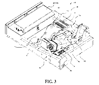
100431 Referring to Figures 1-3, the auxiliary wheel assembly 60 is coupled to
the base 14.
The auxiliary wheel assembly 60 forms part of the drive system 78 in the
illustrated versions. As
noted above, the drive system 78 is configured to influence motion of the
patient support apparatus
during transportation over the floor surface. To this end, the drive system 78
generally includes
a drive member 62 and a motor 80 coupled to the drive member 62 to operate the
drive member
62 at various speeds. In the illustrated versions, the drive member 62 is
realized as an auxiliary
wheel 62 forming part of the auxiliary wheel assembly 60 of an auxiliary wheel
drive system 78
as described in greater detail below. However, those having ordinary skill in
the art will appreciate
that the drive system 78 could be configured in other ways, with various types
of drive members
62 other than those configured as auxiliary wheels 62 of auxiliary wheel
assemblies 60. By way
of non-limiting example, the drive member 62 could be realized by various
types and/or
arrangements of one or more belts, treads, wheels, tires, and the like, which
may be arranged in
various ways about the patient support apparatus 10 and may be deployable,
retractable, or
similarly movable, or may be generally engaged with the floor surface (e.g.,
realized as powered
wheels at one or more corners of the base 14). Other configurations are
contemplated.
Accordingly, it will be appreciated that the auxiliary wheel drive system 78
described and
illustrated herein represents one type of drive system 78 contemplated by the
present disclosure,
and the auxiliary wheel 62 described and illustrated herein represents one
type of drive member
62 contemplated by the present disclosure.
100441 With continued reference to Figures 1-3, the illustrated auxiliary
wheel assembly
60 employs an auxiliary wheel actuator 64 operatively coupled to the auxiliary
wheel 62 and
operable to move the auxiliary wheel 62 between a deployed position 66 (see
Figure 5) engaging
the floor surface, and a retracted position 68 (see Figure 4) spaced away from
and out of contact
8
CA 03223998 2023- 12- 22
WO 2023/043517
PCT/US2022/035048
with the floor surface. The retracted position 68 may alternatively be
referred to as the "fully
retracted position." The auxiliary wheel 62 may also be positioned in one or
more intermediate
positions between the deployed position 66 (see Figure 5) and the retracted
position 68 (Figure 4).
The intermediate positions may alternatively be referred to as a "partially
retracted position," or
may also refer to another "retracted position" (e.g., compared to the "fully"
retracted position 68
depicted in Figure 4). The auxiliary wheel 62 influences motion of the patient
support apparatus
during transportation over the floor surface when the auxiliary wheel 62 is in
the deployed
position 66. In some versions, the auxiliary wheel assembly 60 comprises an
additional auxiliary
wheel movable with the auxiliary wheel 62 between the deployed position 66 and
the retracted
position 68 via the auxiliary wheel actuator 64.
100451 By deploying the auxiliary wheel 62 on the floor surface, the patient
support
apparatus 10 can be easily moved down long, straight hallways or around
corners, owing to a non-
swiveling nature of the auxiliary wheel 62. When the auxiliary wheel 62 is in
the retracted position
68 (see Figure 4) or in one of the intermediate positions (e.g. spaced from
the floor surface), the
patient support apparatus 10 may be subject to moving in an undesired
direction due to
uncontrollable swiveling of the support wheels 50. For instance, during
movement down long,
straight hallways, the patient support apparatus 10 may be susceptible to "dog
tracking," which
refers to undesirable sideways movement of the patient support apparatus 10.
Additionally, when
cornering, without the auxiliary wheel 62 deployed, and with all of the
support wheels 50 able to
swivel, there is no wheel assisting with steering through the corner, unless
one or more of the
support wheels 50 are provided with steer lock capability and the steer lock
is activated.
100461 The auxiliary wheel 62 may be arranged parallel to the longitudinal
axis 18 of the
base 14. The differently, the auxiliary wheel 62 rotates about a rotational
axis R (see Figure 2)
oriented perpendicularly to the longitudinal axis 18 of the base 14 (albeit
offset in some cases from
the longitudinal axis 18). In the version shown, the auxiliary wheel 62 is
incapable of swiveling
about a swivel axis. In some versions, the auxiliary wheel 62 may be capable
of swiveling, but
can be locked in a steer lock position in which the auxiliary wheel 62 is
locked to solely rotate
about the rotational axis R oriented perpendicularly to the longitudinal axis
18. In still other
versions, the auxiliary wheel 62 may be able to freely swivel without any
steer lock functionality
or may be steered.
9
CA 03223998 2023- 12- 22
WO 2023/043517
PCT/US2022/035048
100471 The auxiliary wheel 62 may be located to be deployed inside a perimeter
of the base
14 and/or within a support wheel perimeter defined by the swivel axes 52 of
the support wheels
50. In some versions, such as those employing a single auxiliary wheel 62, the
auxiliary wheel 62
may be located near a center of the support wheel perimeter, or offset from
the center. In this case,
the auxiliary wheel 62 may also be referred to as a fifth wheel. In some
versions, the auxiliary
wheel 62 may be disposed along the support wheel perimeter or outside of the
support wheel
perimeter. In the version shown, the auxiliary wheel 62 has a diameter larger
than a diameter of
the support wheels 50. In some versions, the auxiliary wheel 62 may have the
same or a smaller
diameter than the support wheels 50.
100481 In the version shown in Figure 3, the base 14 comprises a first cross-
member 70
and a second cross-member 72. The auxiliary wheel assembly 60 is disposed
between and coupled
to the cross-members 70, 72. The auxiliary wheel assembly 60 comprises a first
auxiliary wheel
frame 74 coupled to and arranged to articulate (e.g. pivot) relative to the
first cross-member 70.
The auxiliary wheel assembly 60 further comprises a second auxiliary wheel
frame 76 pivotably
coupled to the first auxiliary wheel frame 74 and the second cross-member 72.
The second
auxiliary wheel frame 76 is arranged to articulate and translate relative to
the second cross-member
72.
100491 In the version shown in Figures 2-3, the auxiliary wheel assembly 60
comprises an
auxiliary wheel drive system 78 (described in more detail below) operatively
coupled to the
auxiliary wheel 62. The auxiliary wheel drive system 78 is configured to drive
(e.g. rotate) the
auxiliary wheel 62. In the version shown, the auxiliary wheel drive system 78
comprises the motor
80 coupled to the auxiliary wheel 62 for rotating the auxiliary wheel 62
relative to the support
structure and a motor control circuit 82 (shown in Figures 9 and 10) that is
configured to transmit
control and power signals to the motor 80. The motor control circuit 82 is
also coupled to a power
source 84 (shown schematically in Figure 9) for use in generating the control
and power signals
that are used to operate the motor 80. In the version shown, the motor control
circuit 82 includes
a motor bridge circuit 86 that includes a plurality of field-effect transistor
(FET) switches 88 (e.g.
Ql, Q2, Q3, Q4 shown in Figure 10) that are coupled to motor leads 92 of the
motor 80. In some
versions, the motor 80 includes a 3-phase BLDC motor. In some versions, any
suitable motor may
be used with auxiliary wheel drive system 78.
CA 03223998 2023- 12- 22
WO 2023/043517
PCT/US2022/035048
[0050] The auxiliary wheel drive system 78 also includes a gear train 94 that
is coupled to
the motor 80 and an axle of the auxiliary wheel 62. In the version shown, the
auxiliary wheel 62,
the gear train 94, and the motor 80 are arranged and supported by the second
auxiliary wheel frame
76 to articulate and translate with the second auxiliary wheel frame 76
relative to the second cross-
member 72. In some versions, the axle of the auxiliary wheel 62 is coupled
directly to the second
auxiliary wheel frame 76 and the auxiliary wheel drive system 78 drives the
auxiliary wheel 62 in
another manner. Electrical power is provided from the power source 84 to
energize the motor 80.
The motor 80 converts electrical power from the power source 84 to torque
supplied to the gear
train 94. The gear train 94 transfers torque to the auxiliary wheel 62 to
rotate the auxiliary wheel
62.
[0051] In the version shown, the auxiliary wheel actuator 64 is a linear
actuator comprising
a housing 96 and a drive rod 98 extending from the housing 96. The drive rod
98 has a proximal
end received in the housing 96 and a distal end spaced from the housing 96.
The distal end of the
drive rod 98 is configured to be movable relative to the housing 96 to extend
and retract an overall
length of the auxiliary wheel actuator 64. In the version shown, the auxiliary
wheel assembly 60
also comprises a biasing device such as a spring cartridge 100 to apply a
biasing force. Operation
of the auxiliary wheel actuator 64 and the spring cartridge 100 to
retract/deploy the auxiliary wheel
62 is described in U.S. Patent Application No. 16/690,217, filed on November
21, 2019, entitled,
"Patient Transport Apparatus With Controlled Auxiliary Wheel Deployment,"
which is hereby
incorporated herein by reference.
[0052] Referring to Figures 4 and 5, when moving to the retracted position 68,
auxiliary
wheel actuator 64 retracts the drive rod 98 into the housing 96 to move the
auxiliary wheel 62 from
the deployed position 66 to the retracted position 68. When moving to the
deployed position 66,
auxiliary wheel actuator 64 extends the drive rod 98 from the housing 96 to
move the auxiliary
wheel 62 from the retracted position 68 to the deployed position 66. Various
linkages are
contemplated for such movement, including those disclosed in U.S. Patent
Application No.
16/690,217, filed on November 21, 2019, entitled, "Patient Transport Apparatus
With Controlled
Auxiliary Wheel Deployment," which is incorporated herein by reference. In
some versions, the
housing 96 of the auxiliary wheel actuator 64 may be fixed to the cross member
70 and directly
connected to the auxiliary wheel 62 to directly retract/deploy the auxiliary
wheel 62. Other
configurations are also contemplated.
11
CA 03223998 2023- 12- 22
WO 2023/043517
PCT/US2022/035048
[0053] In some versions, the auxiliary wheel assembly 60 comprises an
auxiliary wheel
brake actuator 102 (shown schematically in Figure 8) operably coupled to the
auxiliary wheel 62
for braking the auxiliary wheel 62. The auxiliary wheel brake actuator 102 may
comprise a brake
member 104 coupled to the base 14 and movable between a braked position
engaging the auxiliary
wheel 62 to brake the auxiliary wheel 62 and a released position permitting
the auxiliary wheel 62
to rotate.
[0054] In the version shown, the auxiliary wheel assembly 60 includes an
auxiliary wheel
assembly control circuit 106 (see Figures 9 and 10) that is coupled to the
auxiliary wheel actuator
64, the auxiliary wheel drive system 78, the auxiliary wheel brake actuator
102, and a power supply
84 for controlling operation of the auxiliary wheel assembly 60. In some
versions, the power
supply 84 may include a pair of rechargeable 12-volt batteries for providing
electrical power to the
auxiliary wheel assembly 60. In some versions, the power supply 84 may include
one or more
batteries that may be rechargeable and/or non-rechargeable and may be rated
for use at voltages
other than 12-volts. In some versions, as shown in Figure 9, the auxiliary
wheel assembly control
circuit 106 includes a printed circuit board 108 mounted to the base 14 and
having a user interface
control unit 110, a brake control unit 112, an auxiliary wheel actuator
control unit 114, and an
auxiliary wheel control unit 116 mounted thereon. The auxiliary wheel assembly
control circuit
106 may also include one or more auxiliary wheel position sensors 118, one or
more auxiliary
wheel speed sensors 120 (shown in Figure 8), an override switch 122 operable
to disconnect power
to the motor 80, and a circuit breaker 124 coupled to the power supply 84.
[0055] In some versions, the auxiliary wheel assembly control circuit 106
includes an
electrical current sense circuit 126 that is configured to sense the
electrical current drawn by the
motor 80 from the power supply 84. The electrical current sense circuit 126
may also be
configured to sense an electrical current through motor phase windings of the
motor 80. In
addition, the electrical current sense circuit 126 may be configured to sense
the electrical current
drawn by the auxiliary wheel brake actuator 102.
[0056] The user interface control unit 110 is configured to transmit and
receive instructions
from the user interface 40 to enable a user to operate the auxiliary wheel
assembly 60 with the user
interface 40. The auxiliary wheel control unit 116 is configured to control
the operation of the
auxiliary wheel drive system 78 based on signals received from the user
interface 40 via the user
interface control unit 110. The brake control unit 112 is configured to
operate the auxiliary wheel
12
CA 03223998 2023- 12- 22
WO 2023/043517
PCT/US2022/035048
brake actuator 102 for braking the auxiliary wheel 62, or may control another
electronic braking
system on the patient support apparatus 10, such as one for the support wheels
50. The auxiliary
wheel actuator control unit 114 is configured to operate the auxiliary wheel
actuator 64 to move
the auxiliary wheel 62 between the deployed and retracted positions. The
auxiliary wheel position
sensor 118 is configured to sense a position of the auxiliary wheel actuator
64. In some versions,
the auxiliary wheel position sensor 118 may include a mid-switch that is
configured to detect a
position of the auxiliary wheel 62 in the deployed position 66, the retracted
position 68, and any
intermediate position between the deployed position 66 and the retracted
position 68. In some
versions, the auxiliary wheel position switch 118 may be configured to read
off a cam surface (not
shown) and indicates when the auxiliary wheel 62 is in a specific position
between fully deployed
and fully retracted. In some versions, two or more limit switches, optical
sensors, hall-effect
sensors, or other types of sensors may be used to detect the current position
of the auxiliary wheel
62.
[0057] The auxiliary wheel speed sensor 120 is configured to sense a
rotational speed of
the auxiliary wheel. In some versions, the auxiliary wheel speed sensor 120
may include one or
more hall effect devices that are configured to sense rotation of the motor 80
(e.g., the motor shaft).
The auxiliary wheel speed sensor 120 may also be used to detect a rotation of
the auxiliary wheel
62 for use in determining whether the auxiliary wheel 62 is in a stop position
and is not rotating.
The auxiliary wheel speed sensor 120 may also be any other suitable sensor for
measuring wheel
speed, such as an optical encoder.
[0058] The override switch 122 is configured to disconnect power to the drive
motor 80 to
enable the auxiliary wheel 62 to rotate more freely. It should be appreciated
that in some versions,
such as that shown in Figure 9, when power to the drive motor 80 is
disconnected, frictional forces
may still be present between the drive motor 80 and auxiliary wheel 62 by
virtue of the gear train
94 such that rotation of the auxiliary wheel 62 is at least partially
inhibited by the gear train 94.
Depending on the nature of the gear train 94, the torque required to overcome
such frictional forces
vary. In some versions, the gear train 94 may be selected to minimize the
torque required to
manually drive the auxiliary wheel 62. In some versions, a clutch may be
employed between the
auxiliary wheel 62 and the gear train 94 that is operated to disconnect the
gear train 94 from the
auxiliary wheel 62 when the override switch 122 is activated. In some
versions, the drive motor
80 may directly drive the auxiliary wheel 62 (e.g., without a gear train), in
which case, the auxiliary
13
CA 03223998 2023- 12- 22
WO 2023/043517
PCT/US2022/035048
wheel 62 may rotate freely when power to the drive motor 80 is disconnected.
If the auxiliary
wheel 62 remains stuck in the deployed position or an intermediate position,
the auxiliary wheel
assembly control circuit 106 may operate the override switch 122 to disconnect
power to the drive
motor 80 and allow the auxiliary wheel 62 to rotate more freely. The circuit
breaker 124 is
configured to trip if an accidental electrical current spike is detected. In
addition, the circuit
breaker 124 may be switched to an "off' position to disconnect the power
supply 84 to save battery
life for storage and shipping.
100591 Although exemplary versions of an auxiliary wheel assembly 60 is
described above
and shown in the drawings, it should be appreciated that other configurations
employing an
auxiliary wheel actuator 64 to move the auxiliary wheel 62 between the
retracted position 68 and
deployed position 66 are contemplated.
100601 In the version shown in Figure 6, the auxiliary wheel drive system 78
is configured
to drive (e.g. rotate) the auxiliary wheel 62 in response to a throttle 128
operable by the user. As
is described in greater detail below in connection with Figures 6-7F, the
throttle 128 is operatively
attached to the first handle 42 in the illustrated version to define a
throttle assembly 130.
100611 In some versions, such as those shown in Figures 6-7F, one or more user
interface
sensors 132 (e.g., capacitive sensors or the like) are coupled to the first
handle 42 to determine
engagement by the user and generate a signal responsive to touch (e.g. hand
placement/contact)
of the user. The one or more user interface sensors 132 are operatively
coupled to the auxiliary
wheel actuator 64 to control movement of the auxiliary wheel 62 between the
deployed position
66 and the retracted position 68. Operation of the auxiliary wheel actuator 64
in response to the
user interface sensor 132 is described in more detail below. In some versions,
the user interface
sensor 132 is coupled to another portion of the patient support apparatus 10,
such as another user
interface 40.
100621 In some versions, such as is depicted in Figure 6, engagement features
or indicia
134 are located on the first handle 42 to indicate to the user where the
user's hands may be placed
on a particular portion of the first handle 42 for the user interface sensor
132 to generate the signal
indicating engagement by the user. For instance, the first handle 42 may
comprise embossed or
indented features to indicate where the user's hand should be placed. In some
versions, the indicia
134 comprises a film, cover, or ink disposed at least partially over the first
handle 42 and shaped
like a handprint to suggest the user's hand should match up with the handprint
for the user interface
14
CA 03223998 2023- 12- 22
WO 2023/043517
PCT/US2022/035048
sensor 132 to generate the signal. In still other versions, the shape of the
user interface sensor 132
acts as the indicia 134 to indicate where the user's hand should be placed for
the user interface
sensor 132 to generate the signal. In some versions (not shown), the patient
support apparatus 10
does not comprise a user interface sensor 132 operatively coupled to the
auxiliary wheel actuator
64 for moving the auxiliary wheel 62 between the deployed position 66 and the
retracted position
68. Instead, a user input device is operatively coupled to the auxiliary wheel
actuator 64 for the
user to selectively move the auxiliary wheel 62 between the deployed position
66 and the retracted
position 68. In some versions, both the user interface sensor 132 and the user
input device are
employed.
100631 Referring now to Figures 7A-7F, the throttle 128 is illustrated in
various positions.
In Figures 7A and 7D, the throttle is in a neutral throttle position N. The
throttle 128 is movable
in a first direction 136 (also referred to as a "forward direction") relative
to the neutral throttle
position N and a second direction 138 (also referred to as a "backward
direction") relative to the
neutral throttle position N opposite the first direction 136. As will be
appreciated from the
subsequent description below, the auxiliary wheel drive system 78 drives the
auxiliary wheel 62
in a forward direction when the throttle 128 is moved in the first direction
136, and in a rearward
direction opposite the forward direction when the throttle 128 is moved in the
second direction
138. When the throttle 128 is disposed in the neutral throttle position N, as
shown in Figure 7A
(see also Figure 7D), the auxiliary wheel drive system 78 does not drive the
auxiliary wheel 62 in
either direction. In many versions, the throttle 128 is spring-biased to the
neutral throttle position
N.
100641 As is described in greater detail below, when the throttle 128 is in
the neutral throttle
position N, the auxiliary wheel drive system 78 may permit the auxiliary wheel
62 to be manually
rotated as a result of a user pushing on the first handle 42 or another user
interface 40 to push the
patient support apparatus 10 in a desired direction. In other words, the motor
80 may be unbraked
and capable of being driven manually.
100651 It should be appreciated that the terms forward and backward are used
to describe
opposite directions that the auxiliary wheel 62 rotates to move the base 14
along the floor surface.
For instance, forward refers to movement of the patient support apparatus 10
with the foot end
leading and backward refers to the head end leading. In some versions,
backward rotation moves
the patient support apparatus 10 in the direction with the foot end leading
and forward rotation
CA 03223998 2023- 12- 22
WO 2023/043517
PCT/US2022/035048
moves the patient support apparatus 10 in the direction with the head end
leading. In such versions,
the handles 42, 44 may be located at the foot end.
100661 Referring to Figure 6, the location of the throttle 128 relative to the
first handle 42
permits the user to simultaneously grasp the handle body 48 of the first
handle 42 and rotate the
throttle 128 about the central axis C defined by the inner support 46. This
allows the user interface
sensor 132, which is operatively attached to the handle body 48 in the
illustrated version, to
generate the signal responsive to touch by the user while the user moves the
throttle 128. In some
versions, the throttle 128 comprises one or more throttle interfaces (e.g.,
ridges, raised surfaces,
grip portions, etc.) for assisting the user with rotating the throttle 128.
100671 In some versions, the throttle assembly 130 may comprise one or more
auxiliary
user interface sensors 140 (shown in phantom), in addition to the user
interface sensor 132, to
determine engagement by the user. In the version illustrated in Figure 6, the
auxiliary user
interface sensors 140 are realized as throttle interface sensors respectively
coupled to each of the
throttle interfaces and operatively coupled to the auxiliary wheel drive
system 78 (e.g., via
electrical communication). The throttle interface sensors are likewise
configured to determine
engagement by the user and generate a signal responsive to touch of the user's
thumb and/or
fingers. When the user is touching one or more of the throttle interfaces, the
throttle interface
sensors generate a signal indicating the user is currently touching one or
more of the throttle
interfaces and movement of the throttle 128 is permitted to cause rotation of
the auxiliary wheel
62. When the user is not touching any of the throttle interfaces, the throttle
interface sensors
generate a signal indicating an absence of the user's thumb and/or fingers on
the throttle interfaces
and movement of the throttle 128 is restricted from causing rotation of the
auxiliary wheel 62. The
throttle interface sensors mitigate the chances for inadvertent contact with
the throttle 128 to
unintentionally cause rotation of the auxiliary wheel 62. The throttle
interface sensors may be
absent in some versions. As is described in greater detail below in connection
with Figure 6, other
types of auxiliary user interface sensors 140 are contemplated by the present
disclosure besides
the throttle interface sensors described above. Furthermore, it will be
appreciated that certain
versions may comprise both the user interface sensor 132 and the auxiliary
user interface sensor
140 (e.g., one or more throttle interface sensors), whereas some versions may
comprise only one
of either the user interface sensor 132 and the auxiliary user interface
sensor 140. Various visual
indicators 142 (e.g., LEDs, displays, illuminated surfaces, etc.) may also be
present on the throttle
16
CA 03223998 2023- 12- 22
WO 2023/043517
PCT/US2022/035048
128 or the handle body 48 to indicate a current operational mode, speed, state
(deployed/retracted),
condition, etc. of the auxiliary wheel assembly 60. Other configurations are
contemplated.
100681 Referring again to Figures 7A-7F, various positions of the throttle 128
are shown.
The throttle 128 is movable relative to the first handle 42 to a first
throttle position, a second
throttle position, and intermediate throttle positions therebetween. The
throttle 128 is operable
between the first throttle position and the second throttle position to adjust
the rotational speed of
the auxiliary wheel.
100691 In some versions, the first throttle position corresponds with the
neutral throttle
position N (shown in Figure 7A and 7D) and the auxiliary wheel 62 is at rest.
The second throttle
position corresponds with a maximum forward throttle position 148 (shown in
Figure 7C) of the
throttle 128 moved in the first direction 136. One intermediate throttle
position corresponds with
an intermediate forward throttle position 150 (shown Figure 7B) of the
throttle 128 between the
neutral throttle position N and the maximum forward throttle position 148.
Here, both the
maximum forward throttle position 148 and the intermediate forward throttle
position 150 may
also be referred to as forward throttle positions.
100701 In other cases, the second throttle position corresponds with a maximum
backward
throttle position 152 (shown in Figure 7F) of the throttle 128 moved in the
second direction 138.
Here, one intermediate throttle position corresponds with an intermediate
backward throttle
position 154 (shown in Figure 7E) of the throttle 128 between the neutral
throttle position N and
the maximum backward throttle position 152. Here, both the maximum backward
throttle position
152 and the intermediate backward throttle position 154 may also be referred
to as backward
throttle positions.
100711 In the versions shown, the throttle 128 is movable from the neutral
throttle position
N to one or more operating throttle positions 146 between, and including, the
maximum backward
throttle position 152 and the maximum forward throttle position 148, including
a plurality of
forward throttle positions between the neutral throttle position N and the
maximum forward
throttle position 148 as well as a plurality of backward throttle positions
between the neutral
throttle position N and the maximum backward throttle position 152. The
configuration of the
throttle 128 and the throttle assembly 130 will be described in greater detail
below.
100721 Figure 8 illustrates a control system 160 of the patient support
apparatus 10. The
control system 160 comprises a controller 162 coupled to, among other
components, the user
17
CA 03223998 2023- 12- 22
WO 2023/043517
PCT/US2022/035048
interface sensors 132, the throttle assembly 130, the auxiliary interface
sensors 140, the auxiliary
wheel assembly control circuit 106, the auxiliary wheel actuator 64, the
auxiliary wheel drive
system 78, the support wheel brake actuator 56, the auxiliary wheel brake
actuator 102, and the
lift assembly 24.
100731 The controller 162 is configured to operate the auxiliary wheel
actuator 64 and the
auxiliary wheel drive system 78. The controller 162 may also be configured to
operate the support
wheel brake actuator 56, the bed lift actuator 26 to operate the lift assembly
24, and the auxiliary
wheel brake actuator 102. The controller 162 is generally configured to detect
the signals from
the sensors and may be further configured to operate the auxiliary wheel
actuator 64 responsive to
the user interface sensor 132 generating signals responsive to touch
100741 The controller 162 comprises one or more microprocessors 164 that are
coupled to
a memory device 166. The memory device 166 may be any memory device suitable
for storage
of data and computer-readable instructions. For example, the memory device 166
may be a local
memory, an external memory, or a cloud-based memory embodied as random access
memory
(RAM), non-volatile RAM (NVRAM), flash memory, or any other suitable form of
memory.
100751 The one or more microprocessors 164 are programmed for processing
instructions
or for processing algorithms stored in memory 166 to control operation of
patient support
apparatus 10. For example, the one or more microprocessors 164 may be
programmed to control
the operation of the auxiliary wheel assembly 60, the support wheel brake
actuator 56, and the lift
assembly 24 based on user input received via the user interfaces 40.
Additionally or alternatively,
the controller 162 may comprise one or more microcontrollers, field
programmable gate arrays,
systems on a chip, discrete circuitry, and/or other suitable hardware,
software, or firmware that is
capable of carrying out the functions described herein. For example, in some
versions, the
instructions and/or algorithms executed by the controller 162 may be performed
in a state machine
configured to execute the instructions and/or algorithms. The controller 162
may be carried on-
board the patient support apparatus 10, or may be remotely located. In some
versions, the
controller 162 may be mounted to the base 14.
100761 The controller 162 comprises an internal clock to keep track of time.
In some
versions, the internal clock may be realized as a microcontroller clock. The
microcontroller clock
may comprise a crystal resonator; a ceramic resonator; a resistor, capacitor
(RC) oscillator; or a
18
CA 03223998 2023- 12- 22
WO 2023/043517
PCT/US2022/035048
silicon oscillator. Examples of other internal clocks other than those
disclosed herein are fully
contemplated. The internal clock may be implemented in hardware, software, or
both.
[0077] In some versions, the memory 166, microprocessors 164, and
microcontroller clock
cooperate to send signals to and operate the lift assembly 24 and the
auxiliary wheel assembly 60
to meet predetermined timing parameters. These predetermined timing parameters
are discussed
in more detail below and are referred to as predetermined durations.
[0078] The controller 162 may comprise one or more subcontrollers configured
to control
the lift assembly 24 and the auxiliary wheel assembly 60, or one or more
subcontrollers for each
of the actuators 26, 56, 64, 102, or the auxiliary wheel drive system 78. In
some cases, one of the
subcontrollers may be attached to the intermediate frame 16 with another
attached to the base 14.
Power to the actuators 26, 56, 64, 102, the auxiliary wheel drive system 78,
and/or the controller
162 may be provided by a battery power supply.
[0079] The controller 162 may communicate with auxiliary wheel assembly
control circuit
106, the actuators 26, 56, 64, 102, and the auxiliary wheel drive system 78
via wired or wireless
connections. The controller 162 generates and transmits control signals to the
auxiliary wheel
assembly control circuit 106, the actuators 26, 56, 64, 102, and the auxiliary
wheel drive system
78, or components thereof, to operate the auxiliary wheel assembly 60 and lift
assembly 24 to
perform one or more desired functions.
100801 In some versions, and as is shown in Figure 8, the control system 160
comprises an
auxiliary wheel position indicator 168 to display a current position of the
auxiliary wheel 62
between or at the deployed position 66 and the retracted position 68, and the
one or more
intermediate positions. In some versions, the auxiliary wheel position
indicator 168 comprises a
light bar that lights up completely when the auxiliary wheel 62 is in the
deployed position 66 to
indicate to the user that the auxiliary wheel 62 is ready to be driven.
Likewise, the light bar may
be partially lit up when the auxiliary wheel 62 is in a partially retracted
position and the light bar
may be devoid of light when the auxiliary wheel 62 is in the fully retracted
position 68. Other
visualization schemes are possible to indicate the current position of the
auxiliary wheel 62 to the
user, such as other graphical displays, text displays, and the like. Such
light indicators or displays
are coupled to the controller 162 to be controlled by the controller 162 based
on the detected
position of the auxiliary wheel 62 as described below. Such indicators may be
located on the
handle 42 or any other suitable location.
19
CA 03223998 2023- 12- 22
WO 2023/043517
PCT/US2022/035048
100811 In the illustrated version, the control system 160 comprises a user
feedback device
170 coupled to the controller 162 to indicate to the user one of a current
speed, a current range of
speeds, a current throttle position, and a current range of throttle
positions. The user feedback
device 170 may be similar to the visual indicators 142 described above, and
also provide feedback
regarding a current operational mode, current state, condition, etc. of the
auxiliary wheel assembly
60. The user feedback device 170 may be placed at any suitable location on the
patient support
apparatus 10. In some versions, the user feedback device 170 comprises one of
a visual indicator,
an audible indicator, and a tactile indicator.
100821 The actuators 26, 56, 64, 102 and the auxiliary wheel drive system 78
described
above may comprise one or more of an electric actuator, a hydraulic actuator,
a pneumatic actuator,
combinations thereof, or any other suitable types of actuators, and each
actuator may comprise
more than one actuation mechanism. The actuators 26, 56, 64, 102 and the
auxiliary wheel drive
system 78 may comprise one or more of a rotary actuator, a linear actuator, or
any other suitable
actuators. The actuators 26, 56, 64, 102 and the auxiliary wheel drive system
78 may comprise
reversible DC motors, or other types of motors. A suitable actuator for the
auxiliary wheel actuator
64 comprises a linear actuator supplied by LINAK A/S located at Smedevwnget 8,
Guderup, DK-
6430, Nordborg, Denmark. It is contemplated that any suitable actuator capable
of deploying the
auxiliary wheel 62 may be utilized.
100831 The controller 162 is generally configured to operate the auxiliary
wheel actuator
64 to move the auxiliary wheel 62 to the deployed position 66 responsive to
detection of the signal
from the user interface sensor 132. When the user touches the first handle 42,
the user interface
sensor 132 generates a signal indicating the user is touching the first handle
42 and the controller
operates the auxiliary wheel actuator 64 to move the auxiliary wheel 62 to the
deployed position
66. In some versions, the controller 162 is further configured to operate the
auxiliary wheel
actuator 64 to move the auxiliary wheel 62 to the retracted position 68
responsive to the user
interface sensor 132 generating a signal indicating the absence of the user
touching the first handle
42.
100841 In some versions, the controller 162 is configured to operate the
auxiliary wheel
actuator 64 to move the auxiliary wheel 62 to the deployed position 66
responsive to detection of
the signal from the user interface sensor 132 indicating the user is touching
the first handle 42 for
a first predetermined duration greater than zero seconds. Delaying operation
of auxiliary wheel
CA 03223998 2023- 12- 22
WO 2023/043517
PCT/US2022/035048
actuator 64 for the first predetermined duration after the controller 162
detects the signal from the
sensor 132 indicating the user is touching the first handle 42 mitigates
chances for inadvertent
contact to result in operation of the auxiliary wheel actuator 64. In some
versions, the controller
162 is configured to initiate operation of the auxiliary wheel actuator 64 to
move the auxiliary
wheel 62 to the deployed position 66 immediately after (e.g., less than 1
second after) the user
interface sensor 132 generates the signal indicating the user is touching the
first handle 42.
[0085] In some versions, the controller 162 is further configured to operate
the auxiliary
wheel actuator 64 to move the auxiliary wheel 62 to the retracted position 68,
or to the one or more
intermediate positions, responsive to the user interface sensor 132 generating
a signal indicating
the absence of the user touching the first handle 42. In some versions, the
controller 162 is
configured to operate the auxiliary wheel actuator 64 to move the auxiliary
wheel 62 to the
retracted position 68, or to the one or more intermediate positions,
responsive to the user interface
sensor 132 generating the signal indicating the absence of the user touching
the first handle 42 for
a predetermined duration greater than zero seconds. In some versions, the
controller 162 is
configured to initiate operation of the auxiliary wheel actuator 64 to move
the auxiliary wheel 62
to the retracted position 68, or to the one or more intermediate positions,
immediately after (e.g.,
less than 1 second after) the user interface sensor 132 generates the signal
indicating the absence
of the user touching the first handle 42.
[0086] In versions including the support wheel brake actuator 56 and/or the
auxiliary wheel
brake actuator 102, the controller 162 may also be configured to operate one
or both brake
actuators 56, 102 to move their respective brake members 58, 104 between the
braked position and
the released position. In some versions, the controller 162 is configured to
operate one or both
brake actuators 56, 102 to move their respective brake members 58, 104 to the
braked position
responsive to the user interface sensor 132 generating the signal indicating
the absence of the user
touching the first handle 42 for a predetermined duration. In some versions,
the predetermined
duration for moving brake members 58, 104 to the braked position is greater
than zero seconds.
In some versions, the controller 162 is configured to initiate operation of
one or both brake
actuators 56, 102 to move their respective brake members 58, 104 to the braked
position
immediately after (e.g., less than 1 second after) the user interface sensor
132 generates the signal
indicating the absence of the user touching the first handle 42.
21
CA 03223998 2023- 12- 22
WO 2023/043517
PCT/US2022/035048
100871 The controller 162 is configured to operate one or both brake actuators
56, 102 to
move their respective brake members 58, 104 to the released position
responsive to the user
interface sensor 132 generating the signal indicating the user is touching the
first handle 42 for a
predetermined duration. In some versions, the predetermined duration for
moving brake members
58, 104 to the released position is greater than zero seconds. In some
versions, the controller 162
is configured to initiate operation of one or both brake actuators 56, 102 to
move their respective
brake members 58, 104 to the released position immediately after (e.g., less
than 1 second after)
the user interface sensor 132 generates the signal indicating the user is
touching the first handle
42.
100881 In some versions, the auxiliary wheel position sensor 118 (also
referred to as a
"position sensor") is coupled to the controller 162 and generates signals
detected by the controller
162. The auxiliary wheel position sensor 118 is coupled to the controller 162
and the controller
162 is configured to detect the signals from the auxiliary wheel position
sensor 118 to detect
positions of the auxiliary wheel 62 as the auxiliary wheel 62 moves between
the deployed position
66, the one or more intermediate positions, and the retracted position 68.
100891 In some versions, the controller 162 is configured to operate one or
both brake
actuators 56, 102 to move their respective brake members 58, 104 to the
released position
responsive to detection of the auxiliary wheel 62 being in the deployed
position 66. In some
versions, the controller 162 is configured to operate one or both brake
actuators 56, 102 to move
their respective brake members 58, 104 to the released position responsive to
detection of the
auxiliary wheel 62 being in a position between the deployed position 66 and
the retracted position
68 (e.g., the one or more intermediate positions).
100901 In some versions, an auxiliary wheel load sensor 172 is coupled to the
auxiliary
wheel 62 and the controller 162, with the auxiliary wheel load sensor 172
configured to generate
a signal responsive to a force of the auxiliary wheel 62 being applied to the
floor surface. In some
versions, the auxiliary wheel load sensor 172 is coupled to the axle of the
auxiliary wheel 62. The
controller 162 is configured to detect the signal from the auxiliary wheel
load sensor 172 and, in
some versions, is configured to operate the auxiliary wheel drive system 78 to
drive the auxiliary
wheel 62 and move the base 14 relative to the floor surface responsive to the
controller 162
detecting signals from the auxiliary wheel load sensor 172 indicating the
auxiliary wheel 62 is in
the partially deployed position engaging the floor surface when a force of the
auxiliary wheel 62
22
CA 03223998 2023- 12- 22
WO 2023/043517
PCT/US2022/035048
on the floor surface exceeds an auxiliary wheel load threshold. This allows
the user to drive the
auxiliary wheel 62 before the auxiliary wheel 62 reaches the fully deployed
position without the
auxiliary wheel 62 slipping against the floor surface.
100911 In some versions, a patient load sensor 174 is coupled to the
controller 162 and to
one of the base 14 and the intermediate frame 16. The patient load sensor 174
generates a signal
responsive to weight, such as a patient being disposed on the base 14 and/or
the intermediate frame
16. The controller 162 is configured to detect the signal from the patient
load sensor 174. Here,
the auxiliary wheel load threshold may change based on detection of the signal
generated by the
patient load sensor 174 to compensate for changes in weight disposed on the
intermediate frame
16 and/or the base 14 to mitigate probability of the auxiliary wheel 62
slipping when the controller
162 operates the auxiliary wheel drive system 78.
100921 In some versions, a patient support apparatus leveling sensor 176 is
coupled to the
controller 162 and to one of the base 14 and the intermediate frame 16. The
leveling sensor 176
generates a signal responsive to the horizontal orientation of the base 14.
The controller 162 is
configured to detect the horizontal orientation of the patient support
apparatus 10 based on signals
received from the leveling sensor 176 and determine whether the patient
support apparatus 10 is
positioned on a ramp, an inclined floor surface, a declined floor surface,
and/or a substantially flat
floor surface.
100931 Each of the sensors described above may comprise one or more of a force
sensor,
a load cell, a speed radar, an optical sensor, an electromagnetic sensor, an
accelerometer, a
potentiometer, an infrared sensor, a capacitive sensor, an ultrasonic sensor,
a limit switch, a level
sensor, a 3-Axis orientation sensor, or any other suitable sensor for
performing the functions
recited herein. Other configurations are contemplated.
100941 In the illustrated versions, where the auxiliary wheel drive system 78
comprises the
motor 80 and the gear train 94, the controller 162 is configured to operate
the motor 80 to drive
the auxiliary wheel 62 and move the base 14 relative to the floor surface
responsive to detection
of the auxiliary wheel 62 being in the at least partially deployed position as
detected by virtue of
the controller 162 detecting the motor 80 drawing electrical power from the
power source 84 above
an auxiliary wheel power threshold, such as by detecting a change in current
draw of the motor 80
associated with the auxiliary wheel 62 being in contact with the floor
surface. In this case,
23
CA 03223998 2023- 12- 22
WO 2023/043517
PCT/US2022/035048
detection of the current drawn by the motor 80 being above a threshold
operates as a form of
auxiliary wheel load sensor 172.
[0095] In some versions, when power is not supplied to the motor 80 from the
power
source 84, the motor 80 acts as a brake to decelerate the auxiliary wheel 62
through the gear train
94. In some versions, the auxiliary wheel 62 is permitted to rotate relatively
freely when power is
not supplied to the motor 80.
[0096] The controller 162 may be programmed to execute the algorithms
operating the
auxiliary wheel assembly 60 in a plurality of operating modes, as described in
U.S. Patent
Application No. 17/131,947, filed on December 23, 2020, entitled, "Patient
Transport Apparatus
With Controlled Auxiliary Wheel Speed," which is hereby incorporated herein by
reference. For
example, the controller 162 may be programmed to operate the auxiliary wheel
assembly 60 in a
drive mode, a free wheel mode, a coast mode, a free wheel speed limiting mode,
and a drag mode.
The controller 162 may also be programmed to quickly turn the modes on/off and
quickly toggle
between modes in certain scenarios.
100971 The controller 162 may additionally be programmed to detect a position
of the
throttle assembly 130 determine a desired rotational speed value associated
with a current
operating throttle position, determine a current rotational speed of the
auxiliary wheel 62, select
an acceleration rate based on the current rotational speed of the auxiliary
wheel 62, generate an
output signal based on the selected acceleration rate, and transmit the
generated output signal to
the motor control circuit 82 to operate the motor 80 to rotate the auxiliary
wheel 62 at the selected
acceleration rate, as described in U.S. Patent Application No. 17/132,009,
filed on December 23,
2020, entitled, -Patient Transport Apparatus With Auxiliary Wheel Control
Systems,- which is
hereby incorporated herein by reference.
[0098] Figure 11 is a flow chart of method 300 illustrating an algorithm that
is executed
by the controller 162 to operate the auxiliary wheel assembly 60 in a
plurality of drive modes.
Figures 12-14 illustrate computer data files that may be used by the
controller 162 when executing
the algorithms illustrated in method 300. The method includes a plurality of
steps. Each method
step may be performed independently of, or in combination with, other method
steps. Portions of
the methods may be performed by any one of, or any combination of, the
components of the
controller 162 and/or the auxiliary wheel assembly control circuit 106. In
some versions, the
controller 162 may include an auxiliary wheel control module 178 that is
configured to execute
24
CA 03223998 2023- 12- 22
WO 2023/043517
PCT/US2022/035048
one more of the algorithms illustrated in method 300. In addition, the
auxiliary wheel control
module 178 may be configured to operate the auxiliary wheel assembly control
circuit 106 to
perform one or more of the algorithm steps illustrated in method 300. In some
versions, the
auxiliary wheel control module 178 may include a state machine configured to
execute the steps
illustrated in method 300. In some versions, the auxiliary wheel control
module 178 may include
computer-executable instructions that are stored in the memory device 166 and
cause one or more
processors 164 of the controller 162 to execute the algorithm steps
illustrated in method 300.
100991 In the illustrated version, the controller 162 is also configured to
generate a plurality
of tables 180, 182, 184 (shown in Figures 12-14) for use in executing the
method 300. The data
tables 180, 182, 184 may be stored as reference database tables in the memory
device 166 and/or
may be stored as computer-executable instructions for generating the data
values included in the
data tables 180, 182, 184. In some versions, a state machine may be used to
generate the data
values included in the data tables 180, 182, 184 that may be used by the
auxiliary wheel control
module 178 in executing the algorithm shown in method 300.
101001 In some versions, the plurality of data tables 180, 182, 184 may
include a speed
value interpolation table 180 (shown in Figure 12), an acceleration rate
interpolation table 182
(shown in Figure 13), and/or a deceleration rate interpolation table 184
(shown in Figure 14). The
speed value interpolation table 180 includes a plurality of data values that
are used to define a
desired rotational speed value of the auxiliary wheel assembly 60 based on the
operating throttle
positions 146 of the throttle assembly 130. For example, as shown in Figure
12, the speed value
interpolation table 180 includes a plurality of operating throttle position
values 186 that are
associated with the plurality of rotational speed values 188. The controller
162 may be configured
to use the speed value interpolation table 180 to operate the auxiliary wheel
assembly 60 to rotate
the auxiliary wheel 62 at a rotational speed that is associated with a
detected operating throttle
position 146. In the illustrated version, each of the operating throttle
position values 186
correspond with a throttle angle of the throttle 128 measured about the
central axis C with respect
to the neutral throttle position N, with the neutral throttle position N
representing a zero angle. In
some versions, the operating throttle position values 186 may correspond to
predefined operating
throttle positions 146 and/or a percentage value of an angle of rotation of
the throttle 128 measured
about the central axis C. In the illustrated version, the rotational speed
values 188 represent a
corresponding rotational speed of the auxiliary wheel 62 measured in miles per
hour. In some
CA 03223998 2023- 12- 22
WO 2023/043517
PCT/US2022/035048
versions, the rotational speed values 188 may represent other units of measure
such as, for
example, feet per second, and/or kilometers per hour. In still other versions,
the rotational speed
values 188 may be expressed as a percentage of a maximum allowable rotation
speed of the
auxiliary wheel assembly 60.
101011 Referring to Figure 13, in some versions, the acceleration rate
interpolation table
182 includes a plurality of acceleration rate values 190 that are associated
with a plurality of
rotational speed values 188. The controller 162 is configured to use the
acceleration rate
interpolation table 182 to select an acceleration rate of the auxiliary wheel
assembly 60 based on
a current rotational speed of the auxiliary wheel 62 when a command is
received from the user via
the user interface 40 and/or the throttle assembly 130. For example, in some
versions, the
controller 162 may receive a command from the user including detecting a
movement of the
throttle assembly 130 from the neutral throttle position N to an operating
throttle position 146
indicating a desire of the user to adjust the speed of the patient support
apparatus 10 using the
auxiliary wheel assembly 60. The controller 162 may be configured to access
the speed value
interpolation table 180 and select a target rotational speed value 188 based
on the detected
operating throttle position 146. The controller 162 then determines a current
rotational speed of
the auxiliary wheel 62 upon receiving the command from the user and accesses
the acceleration
rate interpolation table 182 to select an acceleration rate value 190 based on
the current rotational
speed of the auxiliary wheel 62. Upon selecting the acceleration rate value
190, the controller 162
operates the auxiliary wheel assembly 60 to adjust the rotational speed of the
auxiliary wheel at
the selected acceleration rate 190 until the selected target rotational speed
value 188 is achieved.
101021 In the illustrated version, the acceleration rate interpolation table
182 includes
various groups of rotational speed values having different associated
accelerations rates. For
example, in some versions, the acceleration rate interpolation table 182
includes groups of forward
rotational speed values 192, 194, 196 that are associated with a rotational
speed of the auxiliary
wheel 62 in the forward direction, and groups of reverse rotational speed
values 198, 200, 202 that
are associated with a rotational speed of the auxiliary wheel 62 in the
backward direction.
101031 In some versions, the acceleration rate interpolation table 182
includes a first group
of forward rotational speed values 192 associated with a first acceleration
rate 204, a second group
of forward rotational speed values 194 associated with a second acceleration
rate 206, and a third
group of forward rotational speed values 196 associated with a third
acceleration rate 208. The
26
CA 03223998 2023- 12- 22
WO 2023/043517
PCT/US2022/035048
second acceleration rate 206 is different than the first acceleration rate
204, and the third
acceleration rate 208 is different than the first acceleration rate 204 and
the second acceleration
rate 206. The first group of forward rotational speed values 192 have lower
rotational speed values
than the second group of forward rotational speed values 194, and the first
acceleration rate 204 is
less than the second acceleration rate 206. In addition, the third group of
forward rotational speed
values 196 have higher rotational speed values than the second group of
forward rotational speed
values 194, and the third acceleration rate 208 is less than the first
acceleration rate 204 and the
second acceleration rate 206. In some versions, the acceleration rate
interpolation table 182 may
include additional groups of forward and reverse rotational speed values that
may have different
associated acceleration rates. Other configurations are contemplated.
101041 The acceleration rate interpolation table 182 may also include a first
group of
reverse rotational speed values 198 associated with a fourth acceleration rate
210, a second group
of reverse rotational speed values 200 associated with a fifth acceleration
rate 212, and a third
group of reverse rotational speed values 202 associated with a sixth
acceleration rate 214. The
fifth acceleration rate 212 is different than the fourth acceleration rate
210, and the sixth
acceleration rate 214 is different than the fourth acceleration rate 210 and
the fifth acceleration
rate 212. The first group of reverse rotational speed values 198 have lower
absolute rotational
speed values than the second group of reverse rotational speed values 200, and
the fourth
acceleration rate 210 is less than the fifth acceleration rate 212. The third
group of reverse
rotational speed values 202 have higher absolute rotational speed values than
the second group of
reverse rotational speed values 200, and the sixth acceleration rate 214 is
less than the fourth
acceleration rate 210.
101051 Referring to Figure 14, in some versions, the deceleration rate
interpolation table
184 includes a plurality of deceleration rate values 216 that are associated
with a second plurality
of rotational speed values 188. The controller 162 is configured to use the
deceleration rate
interpolation table 184 to select a deceleration rate of the auxiliary wheel
assembly 60 based on a
current rotational speed of the auxiliary wheel 62 when a command is received
from the user via
the user interface 40 and/or the throttle assembly 130. In the illustrated
version, deceleration rate
interpolation table 184 includes various groups of rotational speed values
having different
associated deceleration rates. For example, in some versions, the deceleration
rate interpolation
table 184 includes groups of forward rotational speed values 218 and 220 that
are associated with
27
CA 03223998 2023- 12- 22
WO 2023/043517
PCT/US2022/035048
a rotational speed of the auxiliary wheel 62 in the forward direction, and
groups of reverse
rotational speed values 222 and 224 that are associated with a rotational
speed of the auxiliary
wheel 62 in the backward direction. For example, in some versions, the
deceleration rate
interpolation table 184 includes a first group of forward rotational speed
values 218 associated
with a first deceleration rate 226, and a second group of forward rotational
speed values 220
associated with a second deceleration rate 228 that is different than the
first deceleration rate 226.
In addition, the first group of forward rotational speed values 218 have lower
rotational speed
values than the second group of forward rotational speed values 220, and the
first deceleration rate
226 is less than the second deceleration rate 228.
101061 The deceleration rate interpolation table 184 may also include a first
group of
reverse rotational speed values 222 associated with a fourth deceleration rate
230, and a second
group of reverse rotational speed values 224 associated with a fifth
deceleration rate 232 that is
different than the fourth deceleration rate 230. The first group of reverse
rotational speed values
222 have lower absolute rotational speed values than the second group of
reverse rotational speed
values 224, and the fourth deceleration rate 230 is less than the fifth
deceleration rate 232. In some
versions, the deceleration rate interpolation table 184 may include additional
groups of forward
and reverse rotational speed values that may have different associated
deceleration rates.
101071 Referring to Figure 11, in some versions, the controller 162 is
programmed to
execute the algorithm illustrated in method 300 for operating the patient
support apparatus 10 in a
drive mode. In method step 302, the controller 162 receives a command from a
user to select a
first drive profile. For example, in some versions, the controller 162
receives a user input from
the graphical user interface 41.
101081 In method step 304, the controller 162 selects the drive profile from a
plurality of
drive profiles stored in the memory device 166. In some configurations, each
of the plurality of
stored drive profiles is associated with a location. For example and not by
way or limitation, a
location may be a medical/healthcare facility. Each of the stored drive
profiles may include a
plurality of drive mode parameters based on the associated location, which may
include, for
example, an architectural layout associated with the location and a driver
training level associated
with the location. An architectural layout associated with a location may
include a plurality of
features such as: length, width, and shape of hallways; ramps or other
features that effect changes
in elevation of floor surface; number and width of hallway corners; bridges
between buildings of
28
CA 03223998 2023- 12- 22
WO 2023/043517
PCT/US2022/035048
a facility; changes in floor surface; elevators; floors of a building;
ingress/egress points of a
building; paths, sidewalks, roads, and the like adjacent to one or more
buildings; and/or any other
feature of the location layout that might affect maneuverability of the
patient support apparatus 10
(e.g., locations defined relative to specific units such as med-surge,
intensive care, radiology, and
the like). A driver training level associated with the location may vary based
on whether a
particular location has dedicated transport personnel, whether the location
requires training of
personnel before a user is allowed to use the patient support apparatus 10,
and/or other factors that
affect how well trained the personnel are to maneuver the patient support
apparatus 10.
[0109] In method step 306, the controller 162 is configured to generate a
signal based on
the selected drive profile. For example, the controller 162 may be programmed
to generate an
output PWM signal based on the selected acceleration rate. In some versions,
the controller 162
may be configured to monitor an electrical current draw from the power source
84 by the motor
80 and generate the output signal based on the selected acceleration rate and
the monitored
electrical current draw from the power source 84.
101101 In method step 308, the controller 162 is configured to transmit the
generated output
signal to the motor control circuit 82 to operate the auxiliary wheel drive
system 78 in a drive
mode based on the selected drive profile. For example, the controller 162 may
be configured to
transmit the generated output signal to the motor control circuit 82 for
operating the plurality of
FET switches 88 of the motor control circuit 82 to control the speed,
acceleration, and rotational
direction of the motor 80 to rotate the auxiliary wheel 62 based on the
selected drive profile.
[0111] Referring to Figure 15, graphical user interface 41 is illustrated. The
graphical user
interface 41 may receive user commands from a user to operate the auxiliary
wheel assembly 60.
A user of the graphical user interface 41 may be chosen from a plurality of
users from a user menu
400 (e.g., via a drop-down list as indicated by the arrow shown in Figure 15).
By way of example
and not limitation, the plurality of users may include all personnel employed
by or associated with
a single facility, or all personnel employed by or associated with a single
owner (e.g., a hospital
system or healthcare group) across more than one facility. In some
configurations, the user may
engage directly with the graphical user interface 41 to make a selection
(e.g., by manually entering
information, which may require a password or other security token before the
user is permitted to
make any selections). In yet other configurations, a physical security token
(e.g., an access card
or USB dongle) may be recognized by the graphical user interface 41 and/or the
controller 162 to
29
CA 03223998 2023- 12- 22
WO 2023/043517
PCT/US2022/035048
authenticate a user. In yet other versions, an electronic security token may
be recognized by the
graphical user interface 41 and/or the controller 162 to authenticate a user
(e.g., Bluetooth, NFC,
RFID, and/or Ultra-wideband signals).
101121 A location of the graphical user interface 41 may be chosen from a
plurality of
locations from a location menu 402 (e.g., via a drop-down list as indicated by
the arrow shown in
Figure 15). By way of example and not limitation, the plurality of locations
may be all facilities
associated with one owner (e.g., a hospital system or healthcare group) or
within a predefined
geographical area. In some configurations, a user may choose a location from
the plurality of
locations. In yet other configurations, a location may be chosen automatically
based on the user
selected from the user menu 400. For example, if a given user is only
associated with a single
facility, the user may not be permitted to select a different facility even if
the owner of the facility
operates more than one facility. In yet other versions, the patient support
apparatus 10 may
automatically detect and select its location. The controller 162 may be
programmed to detect a
location of the patient support apparatus 10, and determine a drive profile or
a plurality of drive
profiles associated with the current location (e.g., a facility or a
particular floor within a facility)
as described in U.S. Patent Application No. 15/910,507, filed on March 2,
2018, entitled,
"Techniques for Dynamic Mapping of a Facility Using Patient Transport
Apparatuses," which is
hereby incorporated herein by reference. In some versions, the controller 162
may be configured
to detect the location of the patient support apparatus 10 by receiving
signals associated with one
or more devices, sensors, and the like either onboard of the patient support
apparatus 10 or from
external devices, tracking systems, and the like, including without limitation
signals generated
based on interaction with devices via Bluetooth, NFC, RFID, and/or Ultra-
wideband signals.
Other configurations are contemplated.
101131 The graphical user interface 41 may further include one or more drive
mode
parameters 404. In some configurations, the drive mode parameters 404 may be
preset and non-
adjustable based on the selected drive profile (e.g., based on the user and/or
location). For
example, a facility may set a drive profile for all its patient support
apparatuses 10 based on a
location that is non-adjustable by any user, and changes to such drive profile
may only be initiated
by an administrator. In other configurations, the facility may set a limited
set of drive profiles for
all its patient support apparatuses 10 based on a location that are non-
adjustable by any user, and
CA 03223998 2023- 12- 22
WO 2023/043517
PCT/US2022/035048
changes to such drive profile may only be initiated by an administrator.
However, in this
configuration, the user may select one of the limited set of drive profiles
for the specified location.
101141 In yet other configurations, a facility may set a drive profile based
on a user (which
may be based on, for example, a training level associated with the user) that
is non-adjustable by
the user, and changes to such drive profiles may only be initiated by an
administrator. In yet other
configurations, one or more of the drive mode parameters 404 may be adjustable
by the user within
certain ranges. In other configurations, the facility may set a limited set of
drive profiles for the
user that are non-adjustable by the user, and changes to such drive profiles
may only be initiated
by an administrator. However, in this configuration, the user may select one
of the limited set of
drive profiles for the specified user.
101151 The drive mode parameters 404 may include, for example and not
limitation, a
rotational speed of the auxiliary wheel, an acceleration rate of the auxiliary
wheel, a deceleration
rate of the auxiliary wheel, a power setting, and a safety setting. One or
more drive mode
parameters described herein may be defined as discrete values, target values
over time, limits such
as maximum and/or minimum values, and the like. In some versions, one or more
drive mode
parameters may be limited in various ways (e.g., within ranges and/or for
certain time periods) for
certain users, within certain locations, and the like. Other configurations
are contemplated. A
power setting may include detection of a battery charge threshold. In some
configurations, the
patient support apparatus 10 may not deploy when a selected drive profile
requires more power
than the current battery charge (e.g., the drive profile is aggressive, with a
high maximum speed
and/or high acceleration or deceleration rate, or when the drive profile
anticipates many inclines,
such as ramps, that require more power for navigating). Each of the drive mode
parameters 404
may include a parameter selector, one of which is labeled 406. In some
configurations, the selector
406 may be a slider that is adjustable between one or more positions, one of
which is labeled 408.
Each of the positions 408 may correspond with a value or range of values
associated with the drive
mode parameter 404.
101161 Referring to Figure 16, the graphical user interface 41 may receive
user commands
from a user to operate the auxiliary wheel assembly 60 in a first drive mode
based on a selected
drive profile (see step 308, method 300 of Figure 11). The first drive mode
may be associated
with one or more drive mode parameters (e.g., the drive mode parameters 404 of
Figure 15).
31
CA 03223998 2023- 12- 22
WO 2023/043517
PCT/US2022/035048
101171 In the illustrated configuration, the first drive mode parameter 500 is
a maximum
speed of the auxiliary wheel assembly 60. The first drive mode parameter 500
may be adjustable
using a first parameter selector 504. In some configurations, the first
parameter selector 504 may
be a slider that is adjustable between one or more positions, one of which is
labeled 506. As
shown, the selected position 506 may be associated with a lower maximum speed
of the auxiliary
wheel assembly 60. In the illustrated configuration, the second drive mode
parameter 502 is an
acceleration rate of the auxiliary wheel assembly 60. The second drive mode
parameter 502 may
be adjustable using a second parameter selector 508. In some configurations,
the second parameter
selector 508 may be a slider that is adjustable between one or more positions,
one of which is
labeled 510. As shown, the selected position 510 may be associated with a
lower acceleration rate
of the auxiliary wheel assembly 60. A lower maximum speed and/or acceleration
rate may be
desirable in certain scenarios, for example, in facilities that include
numerous ramps, uneven
surfaces, large elevation changes, tight corners, narrow hallways, or any
other facility layout that
is likely to make maneuvering the patient support apparatus 10 more difficult
at higher speeds.
For example, facilities with large elevation changes and/or numerous ramps may
use a drive profile
with enhanced ramp detection and/or power settings to ensure safety on
inclines.
101181 Referring to Figures 16A-16B, data files that may be used with an
algorithm
illustrated that may be executed by the control system 160 of the patient
support apparatus 10
shown in Figure 11, according to the drive mode shown in Figure 16, are
illustrated. The data
tables 600, 602 may be stored as reference database tables in the memory
device 166 and/or may
be stored as computer-executable instructions for generating the data values
included in the data
tables 600, 602. In some versions, a state machine may be used to generate the
data values included
in the data tables 600, 602 that may be used by the auxiliary wheel control
module 178 in executing
the algorithm shown in method 300.
101191 In some versions, the plurality of data tables 600, 602 include a speed
value
interpolation table 600 (shown in Figure 16A) and an acceleration rate
interpolation table 602
(shown in Figure 16B). The speed value interpolation table 600 includes a
plurality of data values
that are used to define a desired rotational speed value of the auxiliary
wheel assembly 60 based
on the selected drive profile. For example, as shown in Figure 16A, the speed
value interpolation
table 600 includes a plurality of throttle position values 604 that are
associated with the plurality
of rotational speed values 606. The controller 162 may be configured to use
the speed value
32
CA 03223998 2023- 12- 22
WO 2023/043517
PCT/US2022/035048
interpolation table 600 to operate the auxiliary wheel assembly 60 to rotate
the auxiliary wheel 62
at a rotational speed that is associated with a detected throttle position
604. In the illustrated
version, each of the throttle position values 604 correspond with a throttle
angle of the throttle 128
measured about the central axis C with respect to the neutral throttle
position N, with the neutral
throttle position N representing a zero angle. In some versions, the throttle
position values 604
may correspond to predefined operating throttle positions 146 and/or a
percentage value of an
angle of rotation of the throttle 128 measured about the central axis C. In
the illustrated version,
the rotational speed values 606 represent a corresponding rotational speed of
the auxiliary wheel
62 measured in miles per hour. In some versions, the rotational speed values
606 may represent
other units of measure such as, for example, feet per second, and/or
kilometers per hour. In still
other versions, the rotational speed values 606 may be expressed as a
percentage of a maximum
allowable rotation speed of the auxiliary wheel assembly 60.
[0120] Referring to Figure 16B, in some versions, the acceleration rate
interpolation table
602 includes a plurality of acceleration rate values 608 that are associated
with a plurality of
rotational speed values 606. The controller 162 is configured to use the
acceleration rate
interpolation table 602 to select an acceleration rate of the auxiliary wheel
assembly 60 based on
a current rotational speed of the auxiliary wheel 62 when a command is
received from the user via
the graphical user interface 41. The controller 162 may be configured to
access the speed value
interpolation table 602 and select a target rotational speed value 606 based
on the selected drive
profile and/or adjusted drive mode parameter. The controller 162 then
determines a current
rotational speed of the auxiliary wheel 62 upon receiving the command from the
user and accesses
the acceleration rate interpolation table 602 to select an acceleration rate
value 608 based on the
current rotational speed of the auxiliary wheel 62. Upon selecting the
acceleration rate value 608,
the controller 162 operates the auxiliary wheel assembly 60 to adjust the
rotational speed of the
auxiliary wheel at the selected acceleration rate 608 until the selected
target rotational speed value
606 is achieved.
[0121] In some versions, the acceleration rate interpolation table 602
includes a first group
of forward rotational speed values 610 associated with a first acceleration
rate 612, a second group
of forward rotational speed values 614 associated with a second acceleration
rate 616, and a third
group of forward rotational speed values 618 associated with a third
acceleration rate 620. The
second acceleration rate 616 is different than the first acceleration rate
612, and the third
33
CA 03223998 2023- 12- 22
WO 2023/043517
PCT/US2022/035048
acceleration rate 620 is different than the first acceleration rate 612 and
the second acceleration
rate 616. The first group of forward rotational speed values 610 have lower
rotational speed values
than the second group of forward rotational speed values 614, and the first
acceleration rate 612 is
less than the second acceleration rate 616. In addition, the third group of
forward rotational speed
values 618 have higher rotational speed values than the second group of
forward rotational speed
values 614 and the third acceleration rate 620 is less than the first
acceleration rate 612 and the
second acceleration rate 616. In some versions, the acceleration rate
interpolation table 602 may
include additional groups of forward and reverse rotational speed values that
may have different
associated acceleration rates.
101221 Referring to Figure 17, the graphical user interface 41 may receive
user commands
from a user to operate the auxiliary wheel assembly 60 in a second drive mode
based on a selected
drive profile (see step 308, method 300 of Figure 11). The second drive mode
may be associated
with one or more drive mode parameters (e.g., the drive mode parameters 404 of
Figure 15).
101231 In the illustrated configuration, the second drive mode includes the
first drive mode
parameter 500, which is maximum speed, and the second drive mode parameter
502, which is
acceleration rate, of Figure 16. The first parameter selector 504 is adjusted
to position 512, and
the second parameter selector 508 is adjusted to a position 514. As shown, the
selected positions
512, 514 may be associated with a higher maximum speed and acceleration rate,
respectively, of
the auxiliary wheel assembly 60. A higher maximum speed and/or acceleration
rate may be
desirable in certain scenarios, for example, in facilities that include a
large number of long, straight
and/or wide hallways, few ramps/elevation changes, or any other facility
layout that is likely to
make maneuvering the patient support apparatus 10 less difficult at higher
speeds.
101241 Referring to Figures 17A-17B, data files that may be used with an
algorithm
illustrated that may be executed by the control system 160 of the patient
support apparatus 10
shown in Figure 11, according to the drive mode shown in Figure 17, are
illustrated.
101251 The data tables 700, 702 may be stored as reference database tables in
the memory
device 166 and/or may be stored as computer-executable instructions for
generating the data values
included in the data tables 700, 702. In some versions, a state machine may be
used to generate
the data values included in the data tables 700, 702 that may be used by the
auxiliary wheel control
module 178 in executing the algorithm shown in method 300.
34
CA 03223998 2023- 12- 22
WO 2023/043517
PCT/US2022/035048
101261 In some versions, the plurality of data tables 700, 702 include a speed
value
interpolation table 700 (shown in Figure 17A) and an acceleration rate
interpolation table 702
(shown in Figure 17B). The speed value interpolation table 700 includes a
plurality of data values
that are used to define a desired rotational speed value of the auxiliary
wheel assembly 60 based
on the selected drive profile. For example, as shown in Figure 17A, the speed
value interpolation
table 700 includes a plurality of throttle position values 704 that are
associated with the plurality
of rotational speed values 706. The controller 162 may be configured to use
the speed value
interpolation table 700 to operate the auxiliary wheel assembly 60 to rotate
the auxiliary wheel 62
at a rotational speed that is associated with a detected throttle position
704. In the illustrated
version, each of the throttle position values 704 correspond with a throttle
angle of the throttle 128
measured about the central axis C with respect to the neutral throttle
position N, with the neutral
throttle position N representing a zero angle. In some versions, the throttle
position values 704
may correspond to predefined operating throttle positions 146 and/or a
percentage value of an
angle of rotation of the throttle 128 measured about the central axis C. In
the illustrated version,
the rotational speed values 706 represent a corresponding rotational speed of
the auxiliary wheel
62 measured in miles per hour. In some versions, the rotational speed values
706 may represent
other units of measure such as, for example, feet per second, and/or
kilometers per hour. In still
other versions, the rotational speed values 706 may be expressed as a
percentage of a maximum
allowable rotation speed of the auxiliary wheel assembly 60.
101271 Referring to Figure 17B, in some versions, the acceleration rate
interpolation table
702 includes a plurality of acceleration rate values 708 that are associated
with a plurality of
rotational speed values 706. The controller 162 is configured to use the
acceleration rate
interpolation table 702 to select an acceleration rate of the auxiliary wheel
assembly 60 based on
a current rotational speed of the auxiliary wheel 62 when a command is
received from the user via
the graphical user interface 41. The controller 162 may be configured to
access the speed value
interpolation table 702 and select a target rotational speed value 706 based
on the selected drive
profile and/or adjusted drive mode parameter. The controller 162 then
determines a current
rotational speed of the auxiliary wheel 62 upon receiving the command from the
user and accesses
the acceleration rate interpolation table 702 to select an acceleration rate
value 708 based on the
current rotational speed of the auxiliary wheel 62. Upon selecting the
acceleration rate value 708,
the controller 162 operates the auxiliary wheel assembly 60 to adjust the
rotational speed of the
CA 03223998 2023- 12- 22
WO 2023/043517
PCT/US2022/035048
auxiliary wheel at the selected acceleration rate 708 until the selected
target rotational speed value
706 is achieved.
101281 In some versions, the acceleration rate interpolation table 702
includes a first group
of forward rotational speed values 710 associated with a first acceleration
rate 712, a second group
of forward rotational speed values 714 associated with a second acceleration
rate 716, and a third
group of forward rotational speed values 718 associated with a third
acceleration rate 720. The
second acceleration rate 716 is different than the first acceleration rate
712, and the third
acceleration rate 720 is different than the first acceleration rate 712 and
the second acceleration
rate 716. The first group of forward rotational speed values 710 have lower
rotational speed values
than the second group of forward rotational speed values 714, and the first
acceleration rate 712 is
less than the second acceleration rate 716. In addition, the third group of
forward rotational speed
values 718 have higher rotational speed values than the second group of
forward rotational speed
values 714 and the third acceleration rate 720 is less than the first
acceleration rate 712 and the
second acceleration rate 716. In some versions, the acceleration rate
interpolation table 702 may
include additional groups of forward and reverse rotational speed values that
may have different
associated acceleration rates.
101291 In some versions, speed and/or acceleration control is carried out to
provide: i)
lower accelerations and/or lower speeds in facilities that have layouts that
are more difficult to
maneuver patient support apparatus 10 and/or personnel with lower levels of
training to operate
patient support apparatus 10; and ii) higher accelerations and/or higher
speeds in facilities that
have layouts that are easier to maneuver patient support apparatus 10 and/or
personnel with higher
levels of training to operate patient support apparatus 10.
101301 Several configurations have been discussed in the foregoing
description. However,
the configurations discussed herein are not intended to be exhaustive or limit
the invention to any
particular form. The terminology which has been used is intended to be in the
nature of words of
description rather than of limitation. Many modifications and variations are
possible in light of
the above teachings and the invention may be practiced otherwise than as
specifically described.
101311 The present disclosure also comprises the following clauses, with
specific features
laid out in dependent clauses, that may specifically be implemented as
described in greater detail
with reference to the configurations and drawings above.
36
CA 03223998 2023- 12- 22
WO 2023/043517
PCT/US2022/035048
CLAUSES
I. A patient support apparatus comprising:
a support structure;
a support wheel coupled to the support structure;
a drive system including a drive member coupled to the support structure to
influence
motion of the patient support apparatus over a floor surface, a motor coupled
to the drive member
to operate the drive member at a speed, and a motor control circuit for
transmitting power signals
from a power source to the motor;
a graphical user interface for receiving user commands from a user to operate
the drive
system; and
a control system coupled to the graphical user interface and the drive system
for operating
the drive system, the control system including a memory device configured to
store a plurality of
drive profiles, and a controller coupled to the memory device and configured
to:
receive a first user command to select a first drive profile,
select the first drive profile from the plurality of stored drive profiles,
generate an output signal based on the selected first drive profile, and
transmit the generated output signal to the motor control circuit to operate
the motor
to operate the drive member in a first drive mode based on the selected first
drive profile.
II. The patient support apparatus of clause I, wherein the first drive mode
includes a first
drive mode parameter.
III. The patient support apparatus of clause II, wherein the first drive mode
parameter
includes one of: a rotational speed of the drive member, an acceleration rate
of the drive member,
a deceleration rate of the drive member, and a power setting.
IV. The patient support apparatus of any of clauses I-III, wherein the
controller is further
configured to:
receive a second user command to select a second drive profile;
select the second drive profile from the plurality of stored drive profiles;
generate an output signal based on the selected second drive profile; and
transmit the generated output signal to the motor control circuit to operate
the motor to
operate the drive member in a second drive mode based on the selected second
drive profile.
V. The patient support apparatus of clause IV, wherein:
37
CA 03223998 2023- 12- 22
WO 2023/043517
PCT/US2022/035048
the first drive mode includes a first drive mode parameter;
the second drive mode includes a second drive mode parameter; and
the first drive mode parameter is different from the second drive mode
parameter.
VI. The patient support apparatus of clause V, wherein the first drive mode
parameter and
the second drive mode parameter include one of: a rotational speed of the
drive member, an
acceleration rate of the drive member, a deceleration rate of the drive
member, and a power setting.
VII. The patient support apparatus of any of clauses I-VI, wherein each of the
plurality of
stored drive profiles is associated with a location.
VIII. The patient support apparatus of clause VII, wherein a location
associated with one
of the plurality of stored drive profiles is a medical facility.
IX. The patient support apparatus of any of clauses VII-VIII, wherein each of
the plurality
of stored drive profiles includes a plurality of drive mode parameters defined
based on the location.
X. The patient support apparatus of clause IX, wherein one or more of the
plurality of
drive mode parameters is adjustable by the user.
XI. The patient support apparatus of any of clauses IX-X, wherein at least one
of the
plurality of drive mode parameters is defined based on an architectural layout
associated with the
location.
XII. The patient support apparatus of any of clauses IX-XI, wherein at least
one of the
plurality of drive mode parameters is defined based on a driver training level
associated with the
location.
XIII. The patient support apparatus of any of clauses I-XII, wherein the first
user command
is based on user engagement with the graphical user interface.
XIV. The patient support apparatus of any of clauses I-XIII, wherein the first
user
command is based on a recognized physical security token.
XV. The patient support apparatus of any of clauses I-XIV, wherein the first
user command
is based on a recognized electronic security token.
XVI. A patient support apparatus comprising:
a support structure;
a support wheel coupled to the support structure;
a drive system including a drive member coupled to the support structure to
influence
motion of the patient support apparatus over a floor surface, a motor coupled
to the drive member
38
CA 03223998 2023- 12- 22
WO 2023/043517
PCT/US2022/035048
to operate the drive member at a speed, and a motor control circuit for
transmitting power signals
from a power source to the motor; and
a control system coupled to the drive system for operating the drive system,
the control
system including a memory device configured to store a plurality of drive
profiles, and a controller
coupled to the memory device and configured to:
detect a first drive profile based on at least one of a user input and a
location
associated with the patient support apparatus,
select the first drive profile from the plurality of stored drive profiles,
generate an output signal based on the selected first drive profile, and
transmit the generated output signal to the motor control circuit to operate
the motor
to operate the drive member in a first drive mode based on the selected first
drive profile.
XVII. The patient support apparatus of clause XVI, wherein the first drive
mode includes
a first drive mode parameter.
XVIII. The patient support apparatus of clause XVII, wherein the first drive
mode
parameter includes one of: a rotational speed of the drive member, an
acceleration rate of the drive
member, a deceleration rate of the drive member, and a power setting.
XIX. The patient support apparatus of any of clauses XVI-XVIII, wherein the
controller
is further configured to:
receive a second user command to select a second drive profile;
select the second drive profile from the plurality of stored drive profiles;
generate an output signal based on the selected second drive profile; and
transmit the generated output signal to the motor control circuit to operate
the motor to
operate the drive member in a second drive mode based on the selected second
drive profile.
XX. The patient support apparatus of clause XIX, wherein:
the first drive mode includes a first drive mode parameter;
the second drive mode includes a second drive mode parameter, and
the first drive mode parameter is different from the second drive mode
parameter.
XXI. The patient support apparatus of clause XX, wherein the first drive mode
parameter
and the second drive mode parameter include one of: a rotational speed of the
drive member, an
acceleration rate of the drive member, a deceleration rate of the drive
member, and a power setting.
39
CA 03223998 2023- 12- 22
WO 2023/043517
PCT/US2022/035048
XXII. The patient support apparatus of any of clauses XVI-XXI, wherein each of
the
plurality of stored drive profiles is associated with a location.
XXIII. The patient support apparatus of clause XXII, wherein a location
associated with
one of the plurality of stored drive profiles is a medical facility.
XXIV. The patient support apparatus of any of clauses XVI-XXIII, wherein each
of the
plurality of stored drive profiles includes a plurality of drive mode
parameters defined based on
the location.
XXV. The patient support apparatus of clause XXIV, wherein one or more of the
plurality
of drive mode parameters is adjustable by the user.
XXVI. The patient support apparatus of any of clauses XXIV-XXV, wherein at
least one
of the plurality of drive mode parameters is defined based on an architectural
layout associated
with the location.
XXVII. The patient support apparatus of any of clauses XXIV-XXVI, wherein at
least one
of the plurality of drive mode parameters is defined based on a driver
training level associated with
the location.
XXVIII. The patient support apparatus of any of clauses XVI-XXVII, further
comprising
a graphical user interface for receiving user commands from a user to operate
the drive system.
XXIX. The patient support apparatus of clause XXVIII, wherein the controller
is further
configured to detect the first drive profile based on user engagement with the
graphical user
interface.
XXX. The patient support apparatus of any of clauses XVI-XXIX, wherein the
controller
is further configured to detect the first drive profile based on a recognized
physical security token.
XXXI. The patient support apparatus of any of clauses XVI-XXX, wherein the
controller
is further configured to detect the first drive profile based on a recognized
electronic security token.
XXXII. A patient support apparatus comprising:
a support structure;
a support wheel coupled to the support structure;
a drive system including a drive member coupled to the support structure to
influence
motion of the patient support apparatus over a floor surface, a motor coupled
to the drive member
to operate the drive member at a speed, and a motor control circuit for
transmitting power signals
from a power source to the motor; and
CA 03223998 2023- 12- 22
WO 2023/043517
PCT/US2022/035048
a control system coupled to the drive system for operating the drive system,
the control
system including a memory device configured to store a plurality of drive
profiles, and a controller
coupled to the memory device and configured to:
detect a first location of the patient support apparatus,
select a first drive profile from the plurality of stored drive profiles based
on the
location of the patient support apparatus,
generate an output signal based on the selected first drive profile, and
transmit the generated output signal to the motor control circuit to operate
the motor
to operate the drive member in a first drive mode based on the selected first
drive profile.
XXXIII. The patient support apparatus of clause XXXII, wherein the controller
is further
configured to:
detect a second location associated with the patient support apparatus,
select a second drive profile from the plurality of stored drive profiles
based on the second
location;
generate an output signal based on the selected second drive profile; and
transmit the generated output signal to the motor control circuit to operate
the motor to
operate the drive member in a second drive mode based on the selected second
drive profile.
XXXIV. The patient support apparatus of clause XXXIII, wherein:
the first drive mode includes a first drive mode parameter,
the second drive mode includes a second drive mode parameter, and
the first drive mode parameter is different from the second drive mode
parameter.
XXXV. The patient support apparatus of clause XXX1V, wherein the first drive
mode
parameter and the second drive mode parameter include one of: a rotational
speed of the drive
member, an acceleration rate of the drive member, a deceleration rate of the
drive member, and a
power setting.
XXXV1. A method of operating a drive system coupled to a patient support
apparatus, the
drive system including a drive member for influencing motion of the patient
support apparatus
over a floor surface with a motor coupled to the drive member to operate the
drive member at a
speed and with a motor control circuit for transmitting power signals from a
power source to the
motor, a graphical user interface for receiving user commands from a user to
operate the drive
system, and a control system coupled to the graphical user interface and the
drive system, the
41
CA 03223998 2023- 12- 22
WO 2023/043517
PCT/US2022/035048
control system including a memory device configured to store a plurality of
drive profiles, and a
controller coupled to the memory device, the method including the control
system executing the
steps of:
receiving a first user command to select a first drive profile;
selecting the first drive profile from the plurality of stored drive profiles;
generating an output signal based on the selected first drive profile; and
transmitting the generated output signal to the motor control circuit to
operate the motor to
operate the drive member in a first drive mode based on the selected first
drive profile.
42
CA 03223998 2023- 12- 22