Note: Descriptions are shown in the official language in which they were submitted.
CA 03226220 2024-01-05
WO 2023/283464
PCT/US2022/036587
DRIVEN LIFT AXLES AND ASSOCIATED SYSTEMS AND METHODS
CROSS-REFERENCE TO RELATED APPLICATION(S) INCORPORATED BY
REFERENCE
[0001] The present application claims the benefit of and priority to U.S.
Provisional Patent
Application No. 63/219,770, filed July 8, 2021, and titled "DRIVEN LIFT AXLES
AND
ASSOCIATED SYSTEMS AND METHODS", the disclosure of which is incorporated
herein
by reference in its entirety.
TECHNICAL FIELD
100021 The present disclosure is directed generally to driven lift axles
and, more
particularly, to lift axles having integrated power systems.
BACKGROUND
100031 Many trucks carry loads that vary greatly due to the loading and
unloading of cargo.
To carry heavy loads, some of these trucks use one or more non-drive rear
axles in conjunction
with one or more drive axles. The auxiliary non-drive rear axles may be needed
for a variety of
reasons, including compliance with bridge laws, truck suspension and tire
ratings, etc. In certain
loading conditions or while the vehicle is unloaded, the non-drive axles are
not needed to carry
any load, and instead can negatively impact fuel economy and experience
unnecessary wear.
For this reason, many of these trucks utilize non-drive axles that can be
lifted off of the ground
and into to a stored position (the "lifted position" or "raised position")
when not needed. These
axles are generally referred to as lift axles or liftable axles. By raising
the lift axle when the
vehicle is lightly loaded, wear on the lift axle tires can be reduced and fuel
economy can be
increased due to the absence of rolling resistance from the lift axle tires
and bearing system.
100041 Lift axles can be installed ahead of or behind the drive axles on a
straight truck or
a tractor. If a lift axle is positioned ahead of the drive axle, the lift axle
is referred to as a
"pusher." If the lift axle is positioned behind the drive axle, it is referred
to as a "tag." There
are both steerable and non-steerable lift axles. As the name implies, the
wheels on non-steerable
lift axles cannot turn, and as a result, non-steerable lift axles can be
raised prior to turning a tight
corner depending on the proximity of the non-steerable lift axle to the center
of turning, to
-1-
CA 03226220 2024-01-05
WO 2023/283464
PCT/US2022/036587
prevent rapid tire wear due to scuff and the imposition of high lateral
stresses on the wheels and
other chassis components. Steerable lift axles, also referred to as "self-
steer" axles, include
wheels that caster in response to the vehicle turning so they can remain in
contact with the ground
when the axle is located further away from the center of turning.
10005] A typical over-the-road truck specification is a "6x4" or "six-by-
four"
configuration, with 6 total wheel positions: one front axle having two wheel
positions, and two
rear axles each having two wheel positions. In the 6x4 configuration, four of
the six wheel
positions (typically the wheels on the rear axles) are powered by the engine
through the
transmission and driveshaft(s). In a 6x2 configuration, only one of the two
rear axles is powered,
such that only two of the six wheel positions are driven. For certain use
cases, a 6x2
configuration can provide advantages over a 6x4 configurations in fuel
economy, cost,
complexity, etc. In some instances, the non-driven rear axle in a 6x2
configuration can be a lift
axle that can be raised to reduce tire wear and increase fuel economy.
However, the tractive
performance of a 6x2 configuration is typically reduced from the tractive
performance of a 6x4
configuration since only a single axle is driven.
100061 Various lift axle systems are described in U.S. Patent No. 5,403,031
to Gottschalk
et al., U.S. Patent No. 6,311,993 to Hulstein et al., U.S. Patent No.
6,880,839 to Keeler et al.,
and U.S. Patent No. 9,352,628 to Barton et al., each of which is incorporated
herein by reference
in their entirety.
BRIEF DESCRIPTION OF THE DRAWINGS
10007] Figure 1A is a side view of a vehicle having a lift axle system
configured in
accordance with embodiments of the present technology.
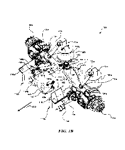
[0008] Figures 1B-1E are perspective, top plan, right side, and exploded
perspective
views, respectively, of a driven lift axle system configured in accordance
with embodiments of
the present technology.
100091 Figure 2-4 are perspective views of driven lift axle systems
configured in
accordance with further embodiments of the present technology.
DETAILED DESCRIPTION
100101 The following disclosure describes various embodiments of driven
lift axles and
associated systems and components for use on heavy duty trucks, trailers,
and/or other vehicles.
-2-
CA 03226220 2024-01-05
WO 2023/283464
PCT/US2022/036587
In some embodiments, driven lift axle systems configured in accordance with
the present
technology include one or more motors mounted to the lift axle to provide
torque to drive the
wheels of the lift axle. Various mounting configurations of such motors are
possible in
accordance with the present technology, such as arranging a motor on the axle
to provide torque
at a conventional driveshaft input, e.g., by interfacing with a differential
drive gear. Other
mounting configurations include positioning a motor at one or both of the
wheel ends of the axle
to provide torque directly to the wheels. In embodiments with a motor at each
of the wheel ends,
each wheel can be driven by a separate motor, additionally allowing for
independent control of
the torque applied to each wheel. The embodiments described herein are
suitable for use with
various types of motors capable of applying torque to the axle and/or wheels,
such as electric
motors, hydraulic motors, internal combustion engines, etc. The systems of the
present
technology are suitable for use on vehicles with or without separate or
additional drive systems,
e.g., internal combustion engines, transmissions, and drivelines.
100111 Other configurations of driven lift axles are also within the scope
of the present
technology, such as twin steer suspension configurations in which two axles
positioned at the
front of the vehicle are steerable and one or both axles are independently
driven and liftable.
Using the driven lift axle systems described herein, one of the twin steer
axles can be lifted under
light loads while maintaining the option to lower the lifted axle and provide
power under heavy
loads. Rail service vehicles may also use embodiments of the driven lift axle
systems of the
present technology to raise the road engaging axles and engage the rail
rollers. Vehicles that use
outriggers for stabilization may have configurations of the driven lift axle
systems that allow all
the axles to be raised (lowering the chassis) such that the outriggers support
the weight and
stabilize the vehicle rather than lift the chassis to provide stabilization.
Other configurations are
also within the scope of the present technology.
[0012] Conventional lift axles cannot feasibly be driven by a driveline
from a conventional
vehicle engine. Conventional driveline configurations that transfer power from
the engine to the
transmission to the rear axles typically require rotating coupling joints
(e.g., universal joints)
that are capable of transferring torque at a range of pinion angles between
the driveline and the
input of the differential. Those of ordinary skill in the art will understand
that the term
"differential," as used herein, can refer to assemblies of gears, friction
discs, or the like that are
configured to transfer input torque (e.g., from a driveline, a motor shaft,
etc.) generally laterally
(e.g., 90 ) from the input direction and to an axle shaft (e.g., a solid axle
shaft, split/half shafts,
etc.). Any differentials may be suitable for use with the embodiments
described herein, such as
-3-
CA 03226220 2024-01-05
WO 2023/283464
PCT/US2022/036587
open differentials, limited slip differentials, clutch-type differentials,
etc. Such driveline to
differential rotating coupling joints are configured to transfer torque at
different pinion angles as
the suspension allows the axle to move up and down relative to the vehicle
chassis during use.
In lift axle systems, the lift axle must be able to travel through an
operating range that is
considerably longer than non-lift axles in order to raise the lift axle wheels
completely off the
ground and provide sufficient clearance of the lift axle wheels to the ground
when lifted. For
example, a typical lift axle rated for 13,500 pounds can be configured to move
approximately up
to nine inches between the ride height (i.e., the position of the suspension
relative to the vehicle
chassis when the vehicle is at rest and the lift axle is in the lowered
position) and the lifted or
raised position. By way of comparison, the distance between the ride height
and the maximum
compressed state of a non-lift axle suspension of similar size would typically
be about three to
four inches. As a result, the pinion angles required when the lift axle is
raised would be beyond
the capabilities of conventional driveline joints. Further, if a conventional
driveline were used
in a pusher lift axle configuration, the non-liftable drive axle rearward of
the lift axle would
presumably have to include an articulating driveline spanning from the lift
axle to the drive axle
(i.e., the third, rearmost axle in a 6x4 configuration) so that power from the
vehicle engine would
drive both the lift axle and the drive axle. Without such an interaxle
driveline, the non-lift axle
would not be driven and the benefits of a 6x2 liftable configuration would not
be realized.
Embodiments of the present technology overcome these problems by directly
driving the wheels
of the lift axle.
10013] Since conventional lift axles are not driven, the suspension systems
for the lift axles
do not require control rods operably coupled between the lift axle and the
frame of the vehicle
for reducing torque effects on the suspension caused by the drive system input
torque. Such
control rods that are operably coupled between the lift axle and the vehicle
frame along the
longitudinal axis of the vehicle are commonly referred to as "torque rods,"
and control rods
operably coupled between the lift axle and the vehicle frame along the lateral
axis of the vehicle
are commonly referred to as "panhard rods." Torque rods generally prevent
excessive rotation
of the axle about an axis parallel to the lift axle (the lateral axis of the
vehicle) during application
of torque to the wheels (drive or braking torque), while panhard rods
generally increase the
lateral stiffness of the suspension during application of torque to the axle
by the drive system
(driveline input torque) by preventing excessive rotation of the axle about
the longitudinal axis
of the vehicle. Some control rod configurations combine the stabilizing
effects of both the torque
-4-
CA 03226220 2024-01-05
WO 2023/283464
PCT/US2022/036587
rods and panhard rods into a single rod assembly commonly referred to as a "v-
rod," which
contributes to both the longitudinal and lateral control of the lift axle
relative to the frame.
[0014] Certain details are set forth in the following description and in
Figures 1A-4 to
provide a thorough understanding of various embodiments of the present
technology. In other
instances, well-known structures, systems, materials and/or operations often
associated with lift
axles and associated components, electric and hydraulic motors, heavy duty
trucks and other
vehicles, etc. are not shown or described in detail in the following
disclosure to avoid
unnecessarily obscuring the description of the various embodiments of the
technology. Those
of ordinary skill in the art will recognize, however, that the present
technology can be practiced
without one or more of the details set forth herein, or with other structures,
methods, components,
and so forth. The terminology used below is to be interpreted in its broadest
reasonable manner,
even though it is being used in conjunction with a detailed description of
certain examples of
embodiments of the technology. Indeed, certain terms may even be emphasized
below; however,
any terminology intended to be interpreted in any restricted manner will be
overtly and
specifically defined as such in this Detailed Description section.
[0015] The accompanying Figures depict embodiments of the present
technology and are
not intended to be limiting of its scope. The sizes of various depicted
elements are not
necessarily drawn to scale, and these various elements may be arbitrarily
enlarged to improve
legibility. Component details may be abstracted in the Figures to exclude
details such as position
of components and certain precise connections between such components when
such details are
unnecessary for a complete understanding of how to make and use the invention.
Additionally,
many of the details, dimensions, angles and other features shown in the
Figures are merely
illustrative of particular embodiments of the disclosure. Accordingly, other
embodiments can
have other details, dimensions, angles and features without departing from the
spirit or scope of
the present disclosure. Those of ordinary skill in the art will also
appreciate that further
embodiments of the invention can be practiced without several of the details
described below.
In the Figures, identical reference numbers identify identical, or at least
generally similar,
elements.
[0016] Figure 1A is a left side (driver side) view of a vehicle 10 having a
lift axle system
22 (e.g., a driven lift axle system as described below with reference to
Figures 1B-4), configured
in accordance with embodiments of the present technology. The vehicle 10
includes a cab 18
mounted to a chassis 12. The chassis 12 has two laterally spaced-apart,
longitudinally extending
-5-
CA 03226220 2024-01-05
WO 2023/283464
PCT/US2022/036587
frame members 14 at a position above a ground surface 20, although only one
frame member 14
can be seen in the side view of Figure 1. The vehicle 10 includes non-liftable
tandem axles 16a
and 16b, of which one or both of the tandem axles 16a and 16b can be drive
axles. In some
embodiments, only a single drive axle can be used with the driven lift axle
systems of the present
technology. Alternatively, any number of drive and lift axles are within the
scope of the present
disclosure. The lift axle assembly 22 can include one or more wheels 24
rotatably mounted on
opposite sides thereof. In operation, a lift axle can raise wheels of the lift
axle off of the ground
when the additional support of the lift axle is not needed (e.g., for tighter
maneuvering, lighter
loading configurations, etc.), and lower wheels into contact with the ground
as shown in Figure
1 when the extra support of the lift axle is needed or desired (e.g., for
bridge laws, heavier loading
configurations, etc.).
[0017] The lift axle system 22 can be attached to the frame members 14
ahead or behind
the tandem axles 16a and 16b (e.g., in a pusher or tag configuration,
respectively). In other
embodiments, the lift axle system 22 can be positioned to replace either or
both of the non-
liftable tandem axles 16a and 16b (e.g., a lift axle system 22 positioned
forward of the non-
liftable axle 16b and replacing the non-liftable axle 16a, a lift axle system
22 positioned rearward
of the non-liftable axle 16a and replacing the non-liftable axle 16b, or two
lift axle systems 22
in tandem positioning replacing both the non-liftable axles 16a and 16b). In
other configurations,
any number of additional non-driven or driven pusher or tag axles can be used
with the non-
liftable axles 16a and 16b and the lift axle system 22. In vehicles with a 6x4
configuration, one
or both of the driven axles in the tandem rear position can be embodiments of
the driven lift axle
systems described herein with reference to Figures 1B-4. In these tandem
driven lift axle system
embodiments, the operator and/or vehicle system can decide which of the two
driven lift axles
is raised based on any suitable parameter. For example, with the forward axle
in the tandem
raised, weight on the rear tandem axle is increased and thereby traction at
the rear tandem tires
is increased. This configuration can be beneficial to prevent situations where
the vehicle may
not be able to start movement from a stopped position. Conversely, when the
rear axle in the
tandem raised, the wheelbase of the vehicle is shortened which results in a
tighter turning radius,
generally improving slow speed maneuverability.
100181 For directional reference in the discussion that follows, it will be
understood that
the vehicle 10 is pointed in a vehicle drive direction VDD and is aligned with
a longitudinal axis
L. Additionally, it will be understood that a vertical axis V extends upwardly
at a right angle to
the longitudinal axis L, and that a lateral axis (not shown) of the vehicle
extends horizontally
-6-
CA 03226220 2024-01-05
WO 2023/283464
PCT/US2022/036587
transverse to the longitudinal axis L. Although the vehicle 10 is depicted as
a concrete mixer
with a tandem axle and tag liftable axle for purposes of illustration, the
driven lift axle systems
described herein can be used with virtually any type of heavy-duty vehicle
including, for
example, other types of trucks, trailers, etc., with the lift axle in either a
tag and pusher
configuration, and with both steerable and non-steerable lift axles.
Accordingly, the various
embodiments of the present technology described herein are not limited to use
with any
particular type of vehicle or in any particular type of axle arrangement
unless specifically noted
otherwise herein.
100191 Figures 1B-1E are perspective, top plan, right side, and exploded
perspective
views, respectively, of a driven lift axle system 100 ("system 100")
configured in accordance
with embodiments of the present technology. In operation, the system 100 can
be moved
between a lowered position (deployed or active) and a raised position (stowed
or inactive). A
number of conventional components typically found on lift axle systems,
including, e.g., wheels,
hardware brackets, lines, and/or wiring, etc. and components of the truck or
tractor chassis (e.g.,
the frame rails) have been omitted from some of the Figures herein for
purposes of clarity.
Further, the following description may describe components on only one side of
the illustrated
lift axle systems for purposes of clarity (e.g., the components on left-hand
side of the vehicle).
It will be appreciated that although only components on one side of the system
100 may be
described herein, the opposite side of the system 100 includes a mirror image
arrangement of the
same or mirrored components, where applicable.
100201 Referring to Figures 1B-1E together, the system 100 includes front
hanger bracket
assemblies 110a and 110b having upper frame brackets 116a and 116b,
respectively, configured
to be attached to two spaced apart, longitudinally extending vehicle frame
rails (not shown) in a
conventional manner. The system 100 further includes trailing arms 112a and
112b having
forward end portions pivotally coupled at pivot pins 111a and 111b (e.g.,
bolts through bushings
(not shown), see Figures 1C and 1D) to the front hanger bracket assemblies
110a and 110b,
respectively, where the pivoting coupling permits movement of the system 100
as it moves
between the lowered and raised positions, as well as permitting movement
during suspension
articulation while the vehicle is driving with the wheels of the lift axle in
contact with the ground.
To control the transition of the system 100 between the lowered and raised
positions, the lift axle
100 further includes air springs 114a and 114b (referred to herein as "lift
springs 114a and 114b")
that are operably coupled between the front hanger bracket assemblies 110a and
110b and the
trailing arms 112a and 112b, each respectively.
-7-
CA 03226220 2024-01-05
WO 2023/283464
PCT/US2022/036587
100211 The system 100 further includes air springs 150a and 150b (referred
to herein as
"load springs 150a and 150b") that operably extend between aft end portions of
the trailing arms
112a and 112b and rear frame brackets 152a and 152b positioned atop the load
springs 150a and
150b. The rear frame brackets 152a and 152b are configured to fixedly attach
upper end portions
of the load springs 150a and 150b to their respective frame rail in a
conventional manner.
Inflation of the load springs 150a and 150b with air or other gas generally
causes extension of
the load spring body and corresponding separation between the aft portion of
the trailing arms
112a and 112b and the rear frame brackets 152a and 152b, respectively. The
system 100 can
include a crossbar 118 to operably couple the aft portion of the trailing arms
112a and 112b
together. The crossbar 118 can prevent excessive torsion on the pivot pins
111a and 111b of the
trailing arms 112a and 112b due to off-center loads of the load springs 150a
and 150b. The
crossbar 118 is further configured to stabilize the pivoting motion of the
trailing arms 112a and
112b such that the left and right sides of the system 100 have synchronized
articulation, have
both wheels lift simultaneously, increase roll stiffness to improve cornering
stability of the
vehicle, etc.
100221 During use of the system 100, deflation of the lift springs 114a and
114b with
corresponding inflation of the load springs 150a and 150b (together the
"lifting system") causes
the trailing arms 112a and 112b to respectively rotate downwardly about the
pivot pins 111a and
111b at the hanger bracket assemblies 110a and 110b and toward the lowered
position. The
pivoting movement of the trailing arms 112a and 112b causes the wheels (not
shown, see, e.g.,
the wheels 24 of Figure 1) of the system 100 contact the ground. Similarly,
inflation of the lift
springs 114a and 114b with corresponding deflation of the load springs 150a
and 150b causes
the trailing arms 112a and 112b to respectively rotate upwardly about the
pivot pins 111a and
111b at the hanger bracket assemblies 110a and 110b and toward the raised
position. In this
regard, the load springs 150a and 150b compress and the wheels of the system
100 raise,
disengaging the wheels from the ground. Examples of air springs are disclosed
in International
PCT Publication No. WO 2006/071172 of Terbom, et al, and in U.S. Patent No.
4,934,667 to
Pees, et al, which are also incorporated herein by reference in their
entireties.
100231 The system 100 further includes an axle assembly 120 having an axle
housing 122
operably coupled to and carried by the trailing arms 112a and 112b. As shown
in Figure 1D, a
medial portion of the trailing arm 112a can include a retaining feature 113a
for receiving a
trailing arm bushing 115a to operably couple the trailing arm 112a to bracket
124a that is
operably coupled to the axle assembly 120. Similarly, a medial portion fo the
trailing arm 112b
-8-
CA 03226220 2024-01-05
WO 2023/283464
PCT/US2022/036587
can be operably coupled to the axle assembly 120 by a bracket 124b (see Figure
1B). The bracket
124a can be operably coupled to the axle housing 122 by welding (e.g., a
weldment), an
integrated component, fasteners, or the like, and can include suitable
features for operably
coupling the trailing arm 112a. In some embodiments, the axle housing 122
includes a
differential cover 125 for protecting the internal components of the axle
assembly 120 from
damage. The axle assembly 120 includes wheel end assemblies 130a and 130b
positioned at
each outer end of the axle housing 122. The internal components of the axle
housing 122 are
not shown for purposes of clarity (e.g., a differential, axle shafts,
bearings, gears, and other
components to direct input torque to the wheel end assemblies 130a and 130b).
A number of
conventional components normally found on wheel end assemblies have not been
labeled or
individually identified herein for purposes of clarity (e.g., brake calipers,
brake discs, wheel
bearings, hubs, etc.). The system 100 may further include components for
controlling the ride
of the system 100 during use, such as shock absorbers 170a and 170b (e.g.,
conventional
hydraulic shock absorbers), that operably extend between the rear frame
brackets 152a and 152b
at a first end and the axle housing 122 at a second end, at which the shock
absorbers 170a and
170b are operably coupled with shock absorber brackets 172a and 172b that are
coupled to the
axle housing 122 e.g., by welding (a weldment), fasteners, or the like. In
other embodiments,
the shock absorbers can operably extend between other components of the system
100, e.g., the
trailing arms 112a and 112b and the frame rails, or other suitable components
to provide damping
to the system 100 during articulation of the suspension.
100241 In some embodiments, the load springs 150a and 150b can be
pneumatically
coupled to the lift springs 114a and 114b, respectively, to facilitate damping
of the non-drive lift
axle, e.g., the auxiliary suspension air damping systems described in U.S.
Patent No. 10,543,730,
filed February 6, 2018, and titled AUXILIARY SUSPENSION AIR DAMPING SYSTEMS
AND ASSOCIATED METHODS OF MANUFACTURE AND USE, which is incorporated
herein by reference in its entirety. In these embodiments, the shock absorber
brackets 172a and
172b can additionally provide damping or may be omitted in favor of the
damping provided by
the pneumatic coupling of the load springs 150a and 150b and the lift springs
114a and 114b.
100251 The system 100 can further include a motor 140 configured to drive
the wheel end
assemblies 130a and 130b. In some embodiments, the motor 140 can be operably
coupled to the
axle housing 122 at the differential cover 125 and configured to provide
torque to an input
component (e.g., a gear, shaft, etc., not shown) of the axle assembly 120. In
some embodiments,
an output shaft (not shown) of the motor 140 can be operably coupled to a
differential drive gear
-9-
CA 03226220 2024-01-05
WO 2023/283464
PCT/US2022/036587
(not shown) contained within the axle housing 122 and differential cover 125
to provide torque
to the axle wheels via an axle shaft (also not shown) at least partially
contained within the axle
housing 122 of the axle assembly 120. The axle assembly 120 can be configured
for use with
the lift axle 100 and include a variety of differential types and gear ratios
dependent on the
intended use and the specified equipment of the vehicle. Further embodiments
of the driven lift
axle systems described herein are suitable for use with axle assemblies having
steerable wheels
disposed on the outer ends of the axle.
100261 The motor 140 can be an electric motor, a hydraulic motor, a
pneumatic motor, an
internal combustion engine, and/or other suitable motor configured to provide
torque to the
wheels of the axle assembly 120. In embodiments having an electric motor, the
motor 140 may
receive electric power at a power connection portion 142 from any suitable
power source. In a
vehicle having electric drive motors powering one or more drive axles, the
same battery bank
providing electric power to the electric motors of the drive axles can be
configured to
additionally power to the motor 140 of the system 100. Alternatively, in a
vehicle having an
internal combustion engine powering one or more drive axles, an auxiliary
power system (e.g.,
an auxiliary battery bank with higher voltage components) may be necessary to
provide power
to the motor 140 of the system 100. In embodiments in which the motor 140 is a
hydraulic
motor, the motor 140 may receive hydraulic power from any suitable power
source, e.g., one or
more hydraulic pumps fluidly coupled to storage tanks and the motor 140 with
hydraulic lines,
etc. In any of these embodiments, the power to the motor 140 may be controlled
manually (e.g.,
by the operator), automatically (e.g., by the vehicle control system and/or
the engine control unit
(ECU) of the vehicle), or any combination thereof, and may be reactive to one
or more road
conditions (e.g., by sensing a loss of traction, by a fuel economy
optimization program, by driver
selectable parameters, etc.). For example, the power to the motor 140 can be
disabled
(automatically or manually) when the system 100 is in the stowed position
(raised), the system
100 may be raised or lowered in reaction to evasive maneuvers of the vehicle,
etc. With any of
the configurations of the present technology, a regenerative braking system
may be integrated
into the system 100 to provide regenerative power to the electrical system of
the vehicle and/or
an auxiliary power system of the motor 140 during coasting and/or braking.
100271 In some embodiments, the axle assembly 120 and the motor 140 can be
at least
generally similar in structure and function to the corresponding components of
the SPICER
Electrified eS20D e-Axle having TM4 electric motor technology provided by Dana
Limited at
3939 Technology Drive, Maumee, OH 43537; or the AXE ELECTRIC AXLE SERIESTM
-10-
CA 03226220 2024-01-05
WO 2023/283464
PCT/US2022/036587
integrated electric axle provided by Allison Transmissions, Inc. at One
Allison Way,
Indianapolis, IN 46222. In other embodiments, the motor 140 is a hydraulic
motor that can be
at least generally similar in structure and function to the MD11 Hydraulic
Motor provided by
Poclain Hydraulics Inc. at 1300 N. Grandview Parkway, Sturtevant, WI 53117; or
the Black
Bruin B200 On-Demand Wheel Motors provided by Black Bruin Inc. Valmetintie 9,
FI-40420
Jyska, Finland. However, further embodiments of the system 100 may include any
suitable axle
assembly 120 and/or motor 140 to provide torque to the system 100. An air kit
used with the
system 100 (e.g., to control the lift and load springs, the brakes, etc.) may
be any typical air
control kit for use with lift axles, such as the STANDARD AIR CONTROL KIT,
Part No.
13501004, provided by Link Manufacturing, Ltd, Sioux Center, IA 51250.
100281 The system 100 further includes a control rod assembly 160,
illustrated in a "v-rod"
configuration, that is operably coupled between the axle housing 122 and the
frame of the
vehicle. The control rod assembly 160 includes rod portions 161a and 161b
extending in a "V"
shape having frame coupling ends 162a and 162b with bushings 164a and 164b,
respectively, at
the open ends of the "V," and an axle coupling end 166 with a bushing 169 at
the point end of
the "V." The frame coupling ends 162a and 162b of the control rod assembly 160
can be
operably coupled through the bushings 164a and 164b, respectively, to the
frame rails with any
suitable connection, e.g., a bracket, a cross member, etc. The axle coupling
end 166 of the
control rod assembly 160 can be operably coupled through the bushing 169 to
the axle housing
122 by a bracket 168 that is operably coupled to a mounting protrusion 167 on
the axle housing
122 by, e.g., welding (a weldment), fasteners (as shown in the illustrated
embodiment), or the
like. The control rod assembly 160 is configured to prevent excessive motion
of the axle
assembly 120 in both the longitudinal and lateral directions relative to the
frame of the vehicle
during torque application by the wheels (which can cause longitudinal rotation
of the axle
assembly 120) and torque application by the motor 140 (which can cause lateral
rotation of the
axle assembly 120). The bushings 164a, 164b, and 169 provide limited movement
in both the
longitudinal and lateral directions relative to the frame of the vehicle as to
limit the stress on
components of the system 100 and provide smoother operation during torque
application by the
motor 140 and/or the wheels. In other embodiments, any suitable joint can be
used at the
coupling ends 162a, 162b, and 166, such as spherical joints, solid joints,
etc.
100291 Figure 2 is a perspective view of a driven lift axle system 200
("system 200")
configured in accordance with other embodiments of the present technology. The
system 200 is
similar in structure, component configuration, and function as the system 100
describe above,
-11-
CA 03226220 2024-01-05
WO 2023/283464
PCT/US2022/036587
except for components related to the control rods of the system 200. Instead
of having a "v-rod"
configuration as shown in the illustrated embodiment of the system 100, the
system 200 includes
a first control rod 280 (e.g., a "panhard rod 280") and a second control rod
286 (e.g., a "torque
rod 286"). The panhard rod 280 operably extends laterally between the axle
assembly 120 and
the frame of the vehicle. The panhard rod 280 has an axle coupling end 282
with a bushing 283,
and a frame coupling end 284 with a bushing 285. The frame coupling end 284 of
the panhard
rod 280 can be operably coupled through the bushing 285 to the frame rails
with any suitable
connection, e.g., a bracket, a cross member, etc. The axle coupling end 282 of
the panhard rod
280 can be operably coupled through the bushing 283 to the axle housing 122 by
a bracket 268
that is operably coupled to the axle housing 122 by, e.g., welding (a
weldment), fasteners, or the
like. The torque rod 286 operably extends longitudinally between the axle
assembly 120 and the
frame of the vehicle. The torque rod 286 has an axle coupling end 288 with a
bushing 289, and
a frame coupling end 290 with a bushing 291. The frame coupling end 290 of the
torque rod
286 can be operably coupled (via, e.g., bolts extending through the bushing
291) to the frame
rails with any suitable connection, e.g., a bracket, a cross member, etc. The
axle coupling end
288 of the torque rod 286 can be operably coupled (via, e.g., bolts extending
through the bushing
289) to the axle housing 122 by the bracket 268. In the illustrated
embodiment, both of the axle
coupling ends 282 and 288 are operably coupled to the axle assembly 120 by a
single bracket
268; however, in other embodiments, each of the axle coupling ends 282 and 288
can be operably
coupled to the axle assembly by separate brackets, weldments, or any other
suitable component.
100301 Figures 3 and 4 are perspective views of driven lift axle systems
300 ("system 300")
and 400 ("system 400"), respectively, configured in accordance with further
embodiments of the
present technology. Certain components of the system 300 are similar in
structure, component
configuration, and function as the system 100 described above, except for
components denoted
by reference numbers in the 300-series. Certain components of the system 400
are similar in
structure, component configuration, and function as the systems 200 and 300
described above
except for components denoted by reference numbers in the 400-series.
[0031] Referring first to Figure 3, the system 300 includes an axle
assembly 320 having
an axle housing 322 (e.g., a beam) extending between the trailing arms 112a
and 112b. The axle
housing 322 can be operably coupled to the trailing arms 112a and 112b by
brackets 324a and
324b configured to operably couple to the axle housing 322 by welding (e.g., a
weldment), an
integrated component, fasteners, or the like, and can include suitable
features for operably
coupling to the trailing arms 112a and 112b, respectively. The axle assembly
320 differs from
-12-
CA 03226220 2024-01-05
WO 2023/283464
PCT/US2022/036587
the axle assembly 120 of systems 100 and 200 by omitting the differential and
centrally mounted
motor 140, and instead including motors 340a and 340b positioned at the
laterally outer ends of
the axle housing 322. The motors 340a and 340b are operable to each drive
wheel end assemblies
330a and 330b, respectively, positioned at the outer ends of the axle assembly
320. Since the
motors 340a and 340b are configured to each operably drive the respective
wheel end assemblies
330a and 330b, the axle housing 322 does not require a differential, gears,
axle shafts, etc.
positioned between the motors 340a and 340b. In some embodiments, other
components of the
system 300 can be included within the axle housing 322, such as wiring or
lines for the motors
340a and 340b, electrical components (e.g., control systems), etc.
[0032] In some embodiments, the motors 340a and 340b are operable to
independently
provide torque to the respective wheel end assemblies 330a and 330b. In this
regard,
embodiments of the system 300 can include various control systems for traction
control, ride
quality, fuel economy, and the like. In these embodiments, the torque provided
by the motors
340a and 340b can be at different levels, or one or both of the motors 340a
and 340b can
unenergized during use of the vehicle depending on traction and/or drive force
requirements,
system performance, electric power level, etc. Alternatively, in other
embodiments a single
motor (similar to motors 340a or 340b) can be configured to drive both of the
wheels of the
driven lift axle system. The motors 340a and 340b can be electric motors,
hydraulic motors,
and/or other suitable motors configured to provide torque to the wheels end
assemblies 330a and
330b, respectively. In embodiments having one or more electric motors, the
motors 340a and
340b may receive electric power from any suitable power source. In a vehicle
having electric
drive motors powering one or more drive axles, the same battery bank providing
electric power
to the electric motors of the drive axles can be configured to additionally
power to the motors
340a and 340b. Alternatively, in a vehicle having an internal combustion
engine powering one
or more drive axles, an auxiliary power system (e.g., an auxiliary battery
bank with higher
voltage components) may be necessary to power to the motors 340a and 340b. In
embodiments
where the motors 340a and 340b are hydraulic motors, the motors 340a and 340b
may receive
hydraulic power from any suitable power source, e.g., one or more hydraulic
pumps fluidly
coupled to storage tanks and the motors 340a and 340b with hydraulic lines,
etc. In any of these
embodiments, the power to the motors 340a and 340b may be controlled manually
(e.g., by the
operator), automatically (e.g., by the vehicle control system and/or the
engine control unit (ECU)
of the vehicle), or any combination thereof, and may be reactive to one or
more road conditions
(e.g., by sensing a loss of traction, by a fuel economy optimization program,
by driver selectable
-13-
CA 03226220 2024-01-05
WO 2023/283464
PCT/US2022/036587
parameters, etc.). With any of the configurations of the present technology, a
regenerative
braking system may be integrated into the system 300 to provide regenerative
power to the
electrical system of the vehicle, and/or to an auxiliary power system of the
motors 340a and
340b, during coasting and/or braking.
[0033] The system 300 includes the "v-rod" style control rod assembly 160
similar to the
control rod configuration of the system 100. The control rod assembly 160 has
the axle coupling
end 166 with the bushing 169 that is operably coupled by the bracket 168 to a
mounting
protrusion 367 on the axle housing 322 by, e.g., welding (a weldment),
fasteners (as shown in
the illustrated embodiment), or the like. The mounting protrusion 367 can have
a similar
configuration to the mounting protrusion 167 of the system 100, but have a
different size, shape,
and/or attachment configuration for operably coupling to the axle housing 322.
[0034] Referring next to Figure 4, the system 400 includes the axle
assembly 320 similar
to the system 300 with the motors 340a and 340b operable to each drive the
wheel end assemblies
330a and 330b, respectively, positioned at the outer ends of the axle assembly
320. The system
400 differs from the system 300 in the control rod configuration. More
specifically, the system
400 has a similar control rod configuration to the system 200¨having the
panhard rod 280 to
control lateral rotation of the axle assembly 320, and the torque rod 286 to
control longitudinal
rotation of the axle assembly 320. The axle coupling end 282 of the panhard
rod 280 can be
operably coupled through the bushing 283 to the axle housing 322 by a bracket
468 that is
operably coupled to the axle housing 322 by, e.g., welding (a weldment),
fasteners, or the like.
The axle coupling end 288 of the torque rod 286 can be operably coupled
through the bushing
289 to the axle housing 322 by the bracket 468. In the illustrated embodiment,
both of the axle
coupling ends 282 and 288 are operably coupled to the axle assembly 320 by a
single bracket
468; however, in other embodiments, each of the axle coupling ends 282 and 288
can be operably
coupled to the axle assembly by separate brackets, weldments, or any other
suitable component.
[0035] Although some embodiments of the driven lift axle systems described
herein
include motors mounted to the axle housing, the axle beam, and/or one or more
of the wheel
ends, other embodiments of the present technology disclosed herein can include
one or more
motors (e.g., electric motors) mounted to other portions of the driven lift
axle system and/or
other portions of the vehicle (e.g., the vehicle frame, vehicle suspension,
etc.). For example, in
some embodiments one or more motors can be mounted to a portion of the vehicle
frame
proximate and/or adjacent to the driven lift axle system, a crossmember of the
frame, an auxiliary
-14-
CA 03226220 2024-01-05
WO 2023/283464
PCT/US2022/036587
bracket, a transmission of the vehicle, any position on an axle beam (e.g., a
medial portion, an
end portion, etc.), a suspension component, etc. Accordingly, embodiments of
the present
technology disclosed herein are not limited to a particular location of the
motor unless the context
clearly requires otherwise.
[0036] In some embodiments, the electric wheel end motors 340a and 340b can
be similar
in structure and function to the motors used with the AxTrax AVE electric
portal axle technology
provided by ZF Friedrichshafen AG/ZF North America, Inc. at 15811 Centennial
Drive,
Northville, MI 48168. However, other embodiments of the systems 300 and 400
can include
any suitable motor configuration to provide torque to the wheel end assemblies
330a and 330b
of the systems 300 and 400.
[0037] Embodiments of lift axle systems configured in accordance with the
present
technology can provide several advantages over conventional truck and tractor
configurations.
For example,: (1) vehicles with lower-powered engine specifications, such as
vehicles with a
6x2 configuration, can receive additional power as needed by one or more
motors of the driven
lift axle; (2) the sensitivity of tractive performance of a 6x2 configuration
to transmission,
wheelbase, and other vehicle parameters can be reduced; (3) traction can be
optimized, or at least
improved, for various loading and road conditions; and/or (4) the lift axle
can be configured to
utilize automatic controls of the drive system to optimize vehicle performance
parameters,
including fuel economy and traction/stability control.
[0038] References throughout the foregoing description to features,
advantages, or similar
language do not imply that all of the features and advantages that may be
realized with the
present technology should be or are in any single embodiment of the invention.
Rather, language
referring to the features and advantages is understood to mean that a specific
feature, advantage,
or characteristic described in connection with an embodiment is included in at
least one
embodiment of the present technology. Thus, discussion of the features and
advantages, and
similar language, throughout this specification may, but do not necessarily,
refer to the same
embodiment. Furthermore, the described features, advantages, and
characteristics of the present
technology may be combined in any suitable manner in one or more embodiments.
One skilled
in the relevant art will recognize that the present technology can be
practiced without one or
more of the specific features or advantages of a particular embodiment. In
other instances,
additional features and advantages may be recognized in certain embodiments
that may not be
present in all embodiments of the present technology.
-15-
CA 03226220 2024-01-05
WO 2023/283464
PCT/US2022/036587
[0039] Any patents and applications and other references noted above,
including any that
may be listed in accompanying filing papers, are incorporated herein by
reference. Aspects of
the invention can be modified, if necessary, to employ the systems, functions,
and concepts of
the various references described above to provide yet further implementations
of the invention.
[0040] Unless the context clearly requires otherwise, throughout the
description and the
claims, the words "comprise," "comprising," and the like are to be construed
in an inclusive
sense, as opposed to an exclusive or exhaustive sense; that is to say, in the
sense of "including,
but not limited to." As used herein, the terms "connected," "coupled," or any
variant thereof
means any connection or coupling, either direct or indirect, between two or
more elements; the
coupling or connection between the elements can be physical, for fluid (e.g.,
air) transfer, logical,
or a combination thereof. Additionally, the words "herein," "above," "below,"
and words of
similar import, when used in this application, refer to this application as a
whole and not to any
particular portions of this application. Where the context permits, words in
the above Detailed
Description using the singular or plural number may also include the plural or
singular number
respectively. The word or, in reference to a list of two or more items, covers
all of the
following interpretations of the word: any of the items in the list, all of
the items in the list, and
any combination of the items in the list.
[0041] The above Detailed Description of examples and embodiments of the
invention is
not intended to be exhaustive or to limit the invention to the precise form
disclosed above. While
specific examples for the invention are described above for illustrative
purposes, various
equivalent modifications are possible within the scope of the invention, as
those skilled in the
relevant art will recognize. The teachings of the invention provided herein
can be applied to
other systems, not necessarily the system described above. The elements and
acts of the various
examples described above can be combined to provide further implementations of
the invention.
Some alternative implementations of the invention may include not only
additional elements to
those implementations noted above, but also may include fewer elements.
Further any specific
numbers noted herein are only examples: alternative implementations may employ
differing
values or ranges.
[0042] While the above description describes various embodiments of the
invention and
the best mode contemplated, regardless how detailed the above text, the
invention can be
practiced in many ways. Details of the system may vary considerably in its
specific
implementation, while still being encompassed by the present disclosure. As
noted above,
-16-
CA 03226220 2024-01-05
WO 2023/283464
PCT/US2022/036587
particular terminology used when describing certain features or aspects of the
invention should
not be taken to imply that the terminology is being redefined herein to be
restricted to any
specific characteristics, features, or aspects of the invention with which
that terminology is
associated. In general, the terms used in the following claims should not be
construed to limit
the invention to the specific examples disclosed in the specification, unless
the above Detailed
Description section explicitly defines such terms. Accordingly, the actual
scope of the invention
encompasses not only the disclosed examples, but also all equivalent ways of
practicing or
implementing the invention under the claims. From the foregoing, it will be
appreciated that
specific embodiments of the invention have been described herein for purposes
of illustration,
but that various modifications may be made without deviating from the spirit
and scope of the
various embodiments of the invention. Accordingly, the invention is not
limited, except as by
the appended claims.
100431 Although certain aspects of the invention are presented below in
certain claim
forms, the applicant contemplates the various aspects of the invention in any
number of claim
forms. Accordingly, the applicant reserves the right to pursue additional
claims after filing this
application to pursue such additional claim forms, in either this application
or in a continuing
application.
-17-